

Page 1
HD-TG Operation Guide
Notice:
Do not attempt to disassemble or alter the test generator housing. There are no user-serviceable parts inside the unit.
Doing so will void your warranty.
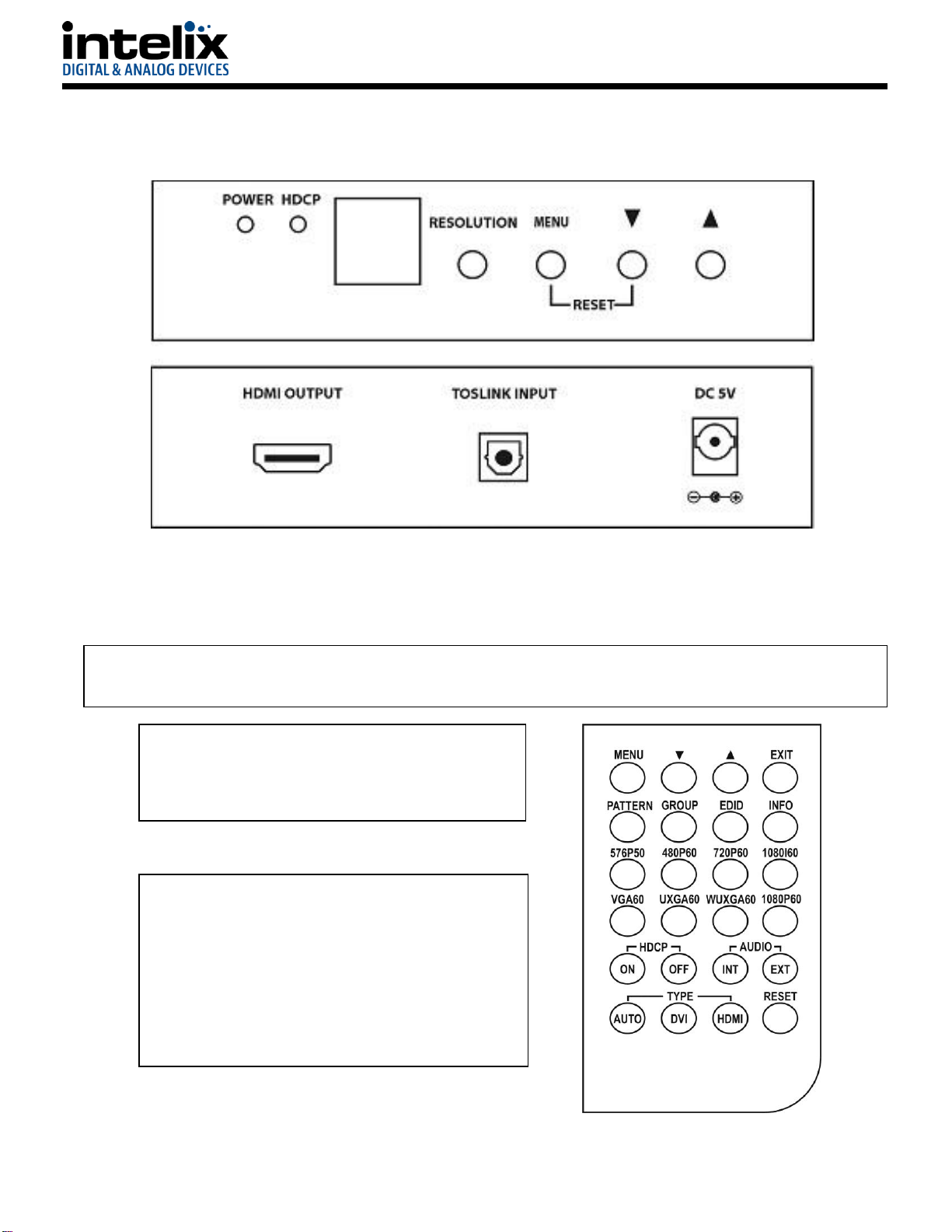
Connecting the HD-TG to a Display Device
Connect the display device’s HDMI input to the output of
the HD-TG and connect the display device’s optical audio
output (if desired) to the HD-TG’s S/PDIF toslink input.
Operating the HD-TG HDMI Test Generator
The HD-TG can be operated from the front panel or the
included IR remote. The on screen display has a menu
that allows the operator to select the various test signals
and functions of the HD-TG. The IR remote has the same
functions as the front panel, plus direct access to many
functions in the menu. A line drawing of the remote can
be seen on the right. See page 2 for an explanation of
how to operate the HD-TG using the front panel controls.
HD-TG HDMI Test Generator Operation Guide
The Intelix HD-TG is an HDMI/DVI-D test generator designed to provide the ability to verify the proper operation of HDMI and
DVI-D display devices, such as monitors and projectors. The HD-TG allows any device with an HDMI input (or DVI-D with an
optional adapter cable) to be tested with various test signals. The HD-TG is designed to test embedded audio, both internally
and externally generated. In addition, the HD-TG tests HDCP functionality, allowing the user to verify proper operation of the
video, audio, and security functions of an HDMI display.
1 www.intelix.com
Page 2

1 Power On/Off LED Indicator
2 HDCP On/Off LED Indicator
3 Remote Control Infrared Sensor
4 Resolution – Switches resolution sequentially in the following order:
VGA60→SVGA60→XGA60→SXGA60→UXGA60→WUXGA60→576p50→
480p60→720p50→720p60→1080i50→1080i60→1080p50→1080p60
5 Menu - Used to display OSD Menu and make selections from the Menu. (Note that the HDCP function turns off
automatically when OSD is present and turns back on when it is no longer visible.) *
6 Down Arrow moves OSD cursor towards the bottom of the display.
7 Up Arrow moves OSD cursor towards the top of the display.
8 Pressing the Menu and Down Arrow buttons at the same time will return the HD-TG to the Factory Default
setting.
* The Menu button is also the Select Button. When you have reached the pattern or adjustment you wish to utilize, pressing
the Menu button allows selection of the desired function or pattern and allows you to enter the sub menus.
Patterns
Selecting “Pattern” on the main menu will take you to a sub-menu with various pattern groups. These pattern groups can be
used to analyze the properties of the display device. The patterns are as follows:
Color Bars - The color bar patterns provide a good overall check on
color performance. This includes the checks of burst keying, subcarrier regeneration, RGB amplifier balance, chrominance/luminance
delay and a color saturation check.
When the output resolution is 1080i, the horizontal Color Bar patterns are not
supported.
Gray Scale - The Gray scale pattern is used to locate non-linearity in a video
amplifier. Non-linearity results in compression of the white level and a loss of high frequency detail.
Purity Check - The available purity colors are White, Blue, Red, Magenta, Green,
Cyan, Yellow and Black. The red and green patterns are most frequently used
for checking color purity.
In a correctly adjusted monitor, only one set of color dots or stripes will be visible. If the red pattern is selected only this color
should be visible; the presence of any other color is an indication that color purity needs adjustment.
The green pattern provides a purity check for three in-line tubes. In addition the pattern serves as a reference to locate any
geometrical distortions in these picture tubes. In the in-line tubes, the guns are in a horizontal position and the green gun is
located in the center.
2 www.intelix.com
Page 3

Blue, as well as the complementary colors, are often used to check the color performance.
The other patterns (mainly RED) are used to ensure that there is no interference between the sound and chroma carrier. In
addition to the primary and complementary colors 100% white can be selected as well as black pattern with color burst. Purity
patterns are also used for measuring unwanted amplitude and phase modulation of the sub-carrier, AM and PM noise as it
occurs with VCRs.
Black/White Lines - The
vertical patterns provide a
quick way to check the color
monitor’s horizontal
bandwidth and phase
behavior. They help verify
video amplifier operation and the display’s color temperature. The horizontal pattern serves as a quick way to check of color
monitor’s vertical bandwidth and phase response. Like the vertical signals, they also are used to verify video amplifier
bandwidth and display color temperature.
When the output resolution is 1080i, the patterns 4, 5 and 6 are not supported.
Gradual - These signals check adjustment of the decoders,
especially the video de-emphasis decoders. In a monitor, the
chrominance signal should have the same amplitude in the
active video portion of the signal.
Grid - This pattern is mainly used for checking and aligning dynamic and corner convergence of TVs or monitors.
When the output resolution is 1080i 50/60, the Grid patterns are not supported.
HDCP - This pattern is used to test DVI and HDMI monitors with HDCP capability. All DVI and HDMI options,
including analyzer options are supported if the HDCP option is installed.
Others - The H pattern is mainly used for checking aligning
dynamic convergence and the Dot pattern is used for checking
and adjusting the static convergence. When using the Dot
pattern, the screen should contain pure white dots. The presence
of colored dots points to problems with focusing and convergence.
The Cross center is used to check and adjust the geometric distortion. The Cross center is ideal to center images on TV
monitors and to facilitate alignment of picture height/picture width. It is also used to check deflection linearity and pincushion
correction.
The Motion pattern is to check the correct digital video processing, especially Analog to Digital conversion. When Motion
pattern is On, the HDCP function will be turned Off. When the user switches to other patterns, the HDCP function will be
turned back On.
3 www.intelix.com
Page 4

Technical Specifications
I/O Connections
Audio Input
SPDIF via Toslink connector
Video Output
Type A HDMI connector (compatible with single link DVI-D)
Frequency Bandwidth
1.65 Gbps (single link)
Supported PC Resolutions
Up to WUXGA/60
Supported TV Resolutions
480p, 576p, 720p, 1080i, 1080p (60 Hz)
Embedded Audio
1 Khz sine wave, 48 Khz sample rate
Control
Front Panel, infrared remote
Compliance
HDMI, HDCP, DVI
Chassis and Environmental
Dimensions (HxWxD)
1.2”x4.9”x4.9” (30x125x125mm)
Shipping Weight
0.72 lbs. (334g)
Operating Temperature
0° to +48° C (+32° to +120° F)
Operating Humidity
10% to 90%, Non-condensing
Storage Temperature
-10° to +70° C (+14° to +158° F)
Storage Humidity
10% to 90%, Non-condensing
Enclosure
Painted Steel
Maximum Power Consumption
6 watts
External Power Supply
5VDC @ 2.6A
Regulatory
CE, RoHS
Other
Warranty
2 years
What’s in the Box
HD-TG Test Generator (1 ea), AC Power Adapter (1 ea), Remote
Control (1 ea), Operation Guide (1 ea)
4 www.intelix.com
 Loading...