

FLX-44 Installaon and
Operaon Guide
Rev 140814
8001 Terrace Ave
Suite 201
Middleton, WI 53562
Phone: 608-831-0880
Toll-Free: 866-462-8649
Fax: 608-831-1833

FLX-44 Installaon Guide
2

FLX-44 Installaon Guide
Important Safety Instrucons
» Please completely read and verify you understand all instrucons in this manual before operang this equipment.
» Keep these instrucons in a safe, accessible place for future reference.
» Heed all warnings.
» Follow all instrucons.
» Do not use this apparatus near water.
» Clean only with a dry cloth.
» Do not install near any heat sources such as radiators, heat registers, stoves, or other apparatus (including ampliers) that
produce heat.
» Use only accessories specied or recommended by Intelix.
» Explanaon of graphical symbols:
◊ Lightning bolt/ash symbol: the lightning bolt/ash and arrowhead within an equilateral triangle
symbol is intended to alert the user to the presence of uninsulated “dangerous voltage” within the
product enclosure which may be of sucient magnitude to constute a risk of shock to a person or
persons.
◊ Exclamaon point symbol: the exclamaon point within an equilateral triangle symbol is intended to
alert the user to the presence of important operang and maintenance (servicing) instrucons in the
literature accompanying the product.
» WARNING: TO REDUCE THE RISK OF FIRE OR ELECTRIC SHOCK, DO NOT EXPOSE THIS APPARATUS TO RAIN OR MOISTURE
AND OBJECTS FILLED WITH LIQUIDS, SUCH AS VASES, SHOULD NOT BE PLACED ON THIS APPARATUS.
» Use the mains plug to disconnect the apparatus from the mains.
» THE MAINS PLUG OF THE POWER CORD MUST REMAIN READILY ACCESSIBLE.
» Do not defeat the safety purpose polarized or grounding-type plug. A polarized plug has two blades with one wider
than the other. A grounding-type plug has two blades and a third grounding prong. The wide blade or the third prong
is provided for your safety. If the provided plug does not t into your outlet, consult an electrician for replacement of
your obsolete outlet. Cauon! To reduce the risk of electrical shock, grounding of the center pin of this plug must be
maintained.
» Protect the power cord from being walked on or pinched parcularly at the plugs, convenience receptacles, and the point
where they exit from the apparatus.
» Do not block the air venlaon openings. Only mount the equipment per Intelix’s instrucons.
» Use only with the cart, stand, table, or rack specied by Intelix or sold with the equipment. When/if a cart is
used, use cauon when moving the cart/equipment combinaon to avoid injury from p-over.
» Unplug this apparatus during lightning storms or when unused for long periods of me.
» Cauon! Shock Hazard. Do not open the unit.
» Refer to qualied service personnel. Servicing is required when the apparatus has been damaged in any way, such as
power supply cord or plug is damaged, liquid has been spilled or objects have fallen into the apparatus, the apparatus has
been exposed to rain or moisture, does not operate normally, or has been dropped.
3

FLX-44 Installaon Guide
Table of Contents
Product Overview ��������������������������������������������������������������������������������������������������������������������������������������������� 6
Package Contents ��������������������������������������������������������������������������������������������������������������������������������������������� 7
Front and Rear Panels ���������������������������������������������������������������������������������������������������������������������������������������8
Front Panel ���������������������������������������������������������������������������������������������������������������������������������������������������������� 8
Rear Panel ����������������������������������������������������������������������������������������������������������������������������������������������������������� 8
IR Remote ��������������������������������������������������������������������������������������������������������������������������������������������������������� 9
Installaon Instrucons ���������������������������������������������������������������������������������������������������������������������������������� 10
Quick Start ��������������������������������������������������������������������������������������������������������������������������������������������������������10
Mount the Matrix ���������������������������������������������������������������������������������������������������������������������������������������������10
Shelf Mounng Instrucons ....................................................................................................................... 10
Rack Mounng Instrucons........................................................................................................................10
Connect Ground ������������������������������������������������������������������������������������������������������������������������������������������������ 10
Connect Sources ������������������������������������������������������������������������������������������������������������������������������������������������ 11
Connect Displays ����������������������������������������������������������������������������������������������������������������������������������������������� 11
HDMI Outputs ............................................................................................................................................11
HDBaseT Outputs .......................................................................................................................................11
Connect Audio Outputs ������������������������������������������������������������������������������������������������������������������������������������� 12
Connect IR Control ��������������������������������������������������������������������������������������������������������������������������������������������12
Source Device and Matrix Control via Remote IR .......................................................................................12
Remote Display Control via IR ....................................................................................................................13
Zone Control via IR ����������������������������������������������������������������������������������������������������������������������������������� 13
Global Control via IR �������������������������������������������������������������������������������������������������������������������������������� 13
Concealed Matrix Control via IR .................................................................................................................13
Connect RS232 Control �������������������������������������������������������������������������������������������������������������������������������������� 14
Matrix Control via RS232 ............................................................................................................................14
Remote RS232 Control via Tunneling .........................................................................................................14
Remote RS232 Control via RS232 Roung ..................................................................................................15
Connect TCP/IP (Ethernet) Control ��������������������������������������������������������������������������������������������������������������������16
Matrix Control via TCP/IP (Ethernet) ..........................................................................................................16
Router Connecon .....................................................................................................................................16
Crossover Cable Connecon .......................................................................................................................16
Web Browser Control .................................................................................................................................17
Remote RS232 Control via TCP/IP Roung .................................................................................................17
Apply Power ������������������������������������������������������������������������������������������������������������������������������������������������������ 18
LCD Panel Boot-up Informaon ������������������������������������������������������������������������������������������������������������������������� 18
4

FLX-44 Installaon Guide
Front Panel and IR Remote Operaon ������������������������������������������������������������������������������������������������������������� 19
Basic Roung ����������������������������������������������������������������������������������������������������������������������������������������������������19
Advanced Roung ��������������������������������������������������������������������������������������������������������������������������������������������� 19
IR Remote Operaon ����������������������������������������������������������������������������������������������������������������������������������������� 20
Web Browser Control �������������������������������������������������������������������������������������������������������������������������������������� 21
End User Login ��������������������������������������������������������������������������������������������������������������������������������������������������21
Matrix Control ��������������������������������������������������������������������������������������������������������������������������������������������������� 21
Administrator Login ������������������������������������������������������������������������������������������������������������������������������������������22
Matrix Control and Setup Access ����������������������������������������������������������������������������������������������������������������������22
Web Browser Customizaon ��������������������������������������������������������������������������������������������������������������������������� 23
Users Tab �����������������������������������������������������������������������������������������������������������������������������������������������������������23
Interface Tab ����������������������������������������������������������������������������������������������������������������������������������������������������� 23
HDCP and EDID Conguraon Tab �������������������������������������������������������������������������������������������������������������������� 24
Network Tab (IP Address) ���������������������������������������������������������������������������������������������������������������������������������� 25
EDID Management ����������������������������������������������������������������������������������������������������������������������������������������� 26
Full EDID Copy ��������������������������������������������������������������������������������������������������������������������������������������������������� 26
Hybrid EDID Copy ���������������������������������������������������������������������������������������������������������������������������������������������� 26
RS232 and TCP/IP Commands ������������������������������������������������������������������������������������������������������������������������� 27
Roung Commands ������������������������������������������������������������������������������������������������������������������������������������������� 27
Preset Commands ��������������������������������������������������������������������������������������������������������������������������������������������� 28
System Commands ��������������������������������������������������������������������������������������������������������������������������������������������28
EDID Commands �����������������������������������������������������������������������������������������������������������������������������������������������28
HDCP Commands ���������������������������������������������������������������������������������������������������������������������������������������������� 29
Remote RS232 Control via Roung .............................................................................................................29
Troubleshoong ���������������������������������������������������������������������������������������������������������������������������������������������30
Matrix does not power on ��������������������������������������������������������������������������������������������������������������������������������� 30
Cannot view 3D content ������������������������������������������������������������������������������������������������������������������������������������30
Cannot hear surround sound audio ������������������������������������������������������������������������������������������������������������������30
No video from HDBaseT output ������������������������������������������������������������������������������������������������������������������������30
Technical Specicaons ����������������������������������������������������������������������������������������������������������������������������������31
5

FLX-44 Installaon Guide
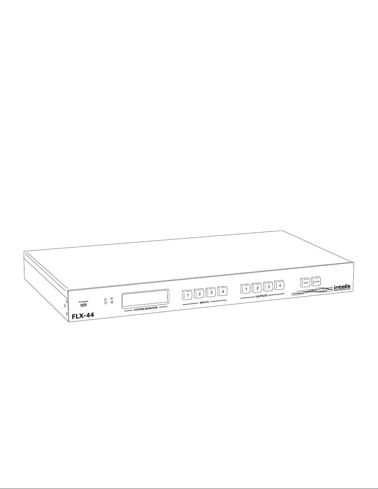
Product Overview
The Intelix FLX-44 is a four input by four output HDBaseT/HDMI matrix switcher. The Intelix FLX-44 matrix improves
the ease of installaon similar to previous Intelix HDMI matrix switchers.
The FLX-44 features HDBaseT twisted pair extension for each output, and simultaneous HDMI on the rst two
outputs, allowing the same signal to be routed to the HDMI connector and a remote desnaon with an HDBaseT
receiver. The HDBaseT ports support 1080p HDMI video with audio, bidireconal wide-band IR, matrix control
via IR, RS232 tunneling, and HDCP up to 60 meters (196 feet). Each HDBaseT output port supplies power to the
aached extender, eliminang the need for a power supply at the display end. Each output features stereo audio
de-embedding for connecon to ampliers or DSPs.
The FLX-44 can be controlled via front panel buons, front panel IR, external IR, remote IR through HDBaseT
extenders, RS232, and Ethernet. Clear buon caps provide legible text on the front panel, which can be customized
for each installaon. The matrix includes a simple IR remote control to allow IR switching. This IR remote control
can be learned into universal remotes and IR based control systems. An IR All In port is provided, which allow one
IR connecon to control all four remote displays.
The matrix also features a full command set for RS232 and Ethernet control with third party control systems, plus
control via a web browser. RS232 commands to remote displays can also be embedded in the control stream
through the matrix from both the RS232 and Ethernet control ports, which will reduce the number of serial ports
required for the control system.
The FLX-44 is HDMI compable and supports up to 2K resoluons, Deep Color, and full 3D capabilies. The matrix
features advanced EDID and HDCP handling, including the ability to turn HDCP compliance ON and OFF to ensure
maximum funconality with a wide range of sources.
6

Package Contents
Please verify the following items are in the shipping box prior to installaon of the FLX-44.
FLX-44 Installaon Guide
FLX-44 Matrix Switcher
1 ea
Rack Ears with Screws
2 ea
US Power Cable
1 ea
Shelf Feet with Screws
4 ea
48V DC 1.6A Power
Supply
1 ea
RS232 Cable
1 ea
Infrared Remote Control
1 ea
Removable 3-pole
Terminal Blocks
(installed on matrix)
8 ea
AAA Baeries
2 ea
FLX-44 Installaon and
Operaon Guide
1 ea
7
FLX-44 Installaon Guide
Front and Rear Panels
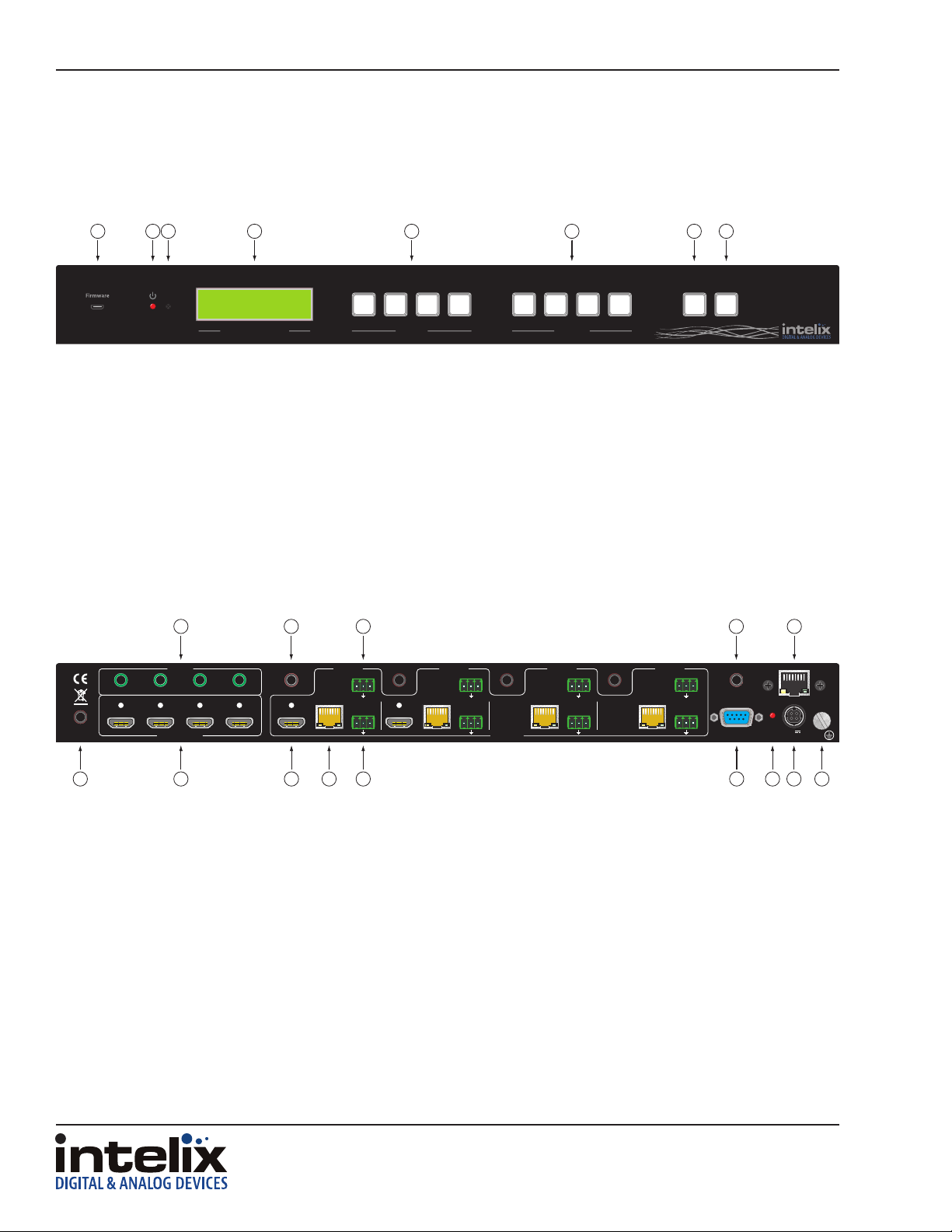
Front Panel
1 2 3 4 5 6 7 8
FLX-44
1. Micro USB port for rmware updang
2. Power indicator LED
3. IR receiver for matrix control via IR remote
4. LCD screen
5. Input select buons
6. Output select buons
7. Take buon – conrms route changes and applies new route
8. Clear buon – cancels current roung selecon before change is applied
Rear Panel
1 2 3 4
1 2 3 4
IR ALL IN
IR
SYSTEM MONITOR
1 2
3
4
INPUTS OUTPUTS
1 2
3
4
TAKE CLEAR
A B C D E
ZONE 1
IR OUT
HDMI INPUT S
IR IN
IR IN
HDMI
HDMI
1
1
Twiste d Pair
Twiste d Pair
ZONE 1
RS232
RS232
Tx Rx
Tx Rx
Audio
Audio
L R
L R
IR IN
IR IN
HDMI
HDMI
2
Twisted Pai r
ZONE 2
RS232
Tx Rx
Audio
L R
IR IN
IR IN
OUTPUTS
3
Twisted Pai r
ZONE 3
RS232
Tx Rx
Audio
L R
4
Twiste d Pair
ZONE 4
RS232
Tx Rx
Audio
L R
IR IN
IR IN
IR EYE
RS232
TCP/IP
48V
1.6A MAX
F G H I J K L M N
A. IR output ports for each HDMI source
B. IR input ports for each HDBaseT output
C. RS232 input for each HDBaseT output
D. IR input for matrix when front is covered or matrix is located in a concealed locaon
E. TCP/IP (Ethernet) control input; also allows control via web browser
F. IR input for all HDBaseT outputs
G. HDMI inputs
H. HDMI outputs (outputs 1 and 2 only)
I. HDBaseT outputs with PoE support
J. Analog audio output
K. RS232 control input
L. Power LED
M. 48V DC power input
N. Ground screw
8
FLX-44 Installaon Guide
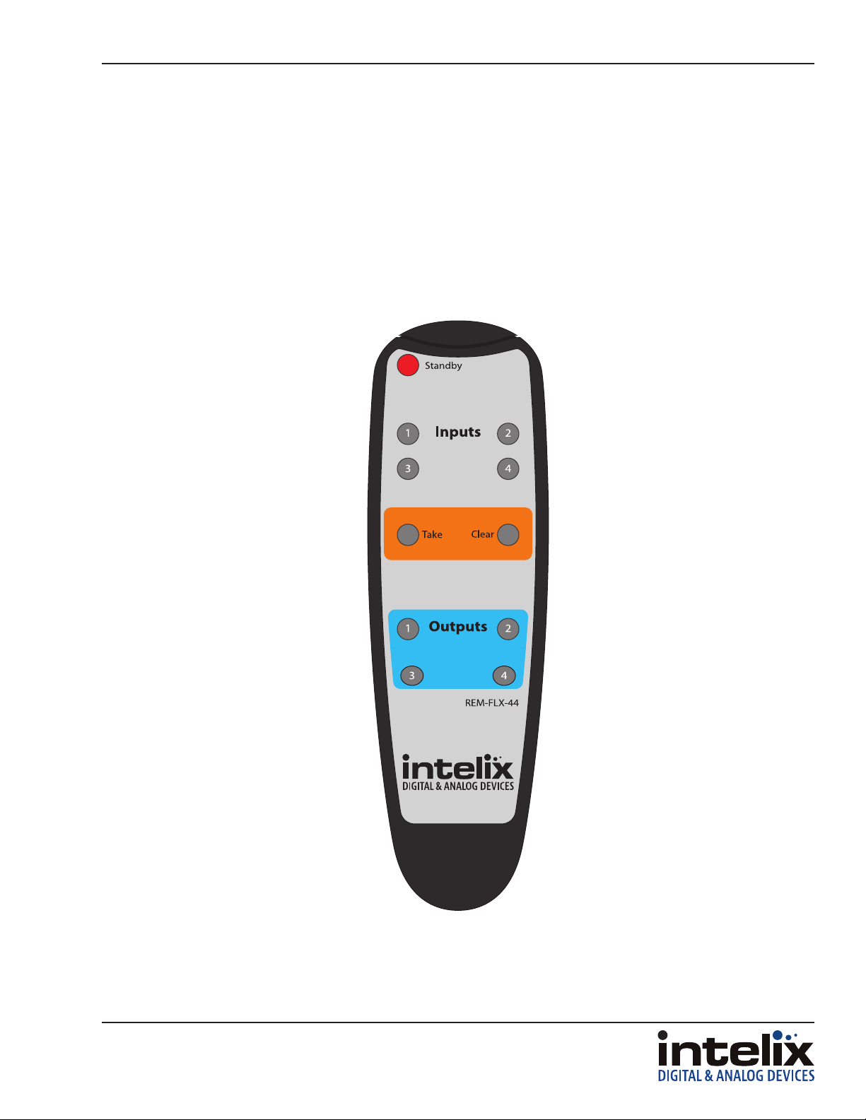
IR Remote
The included IR remote performs all of the funcons available on the front panel of the FLX-44. Please see
page 19 for informaon on controlling the matrix from the front panel and the IR remote.
The remote control requires two AAA baeries, which are included.
9
FLX-44 Installaon Guide
Installaon Instrucons
Quick Start
1. Mount the matrix
2. Connect ground (oponal)
3. Connect sources
4. Connect displays
5. Connect audio outputs (oponal)
6. Connect control (oponal)
7. Apply power
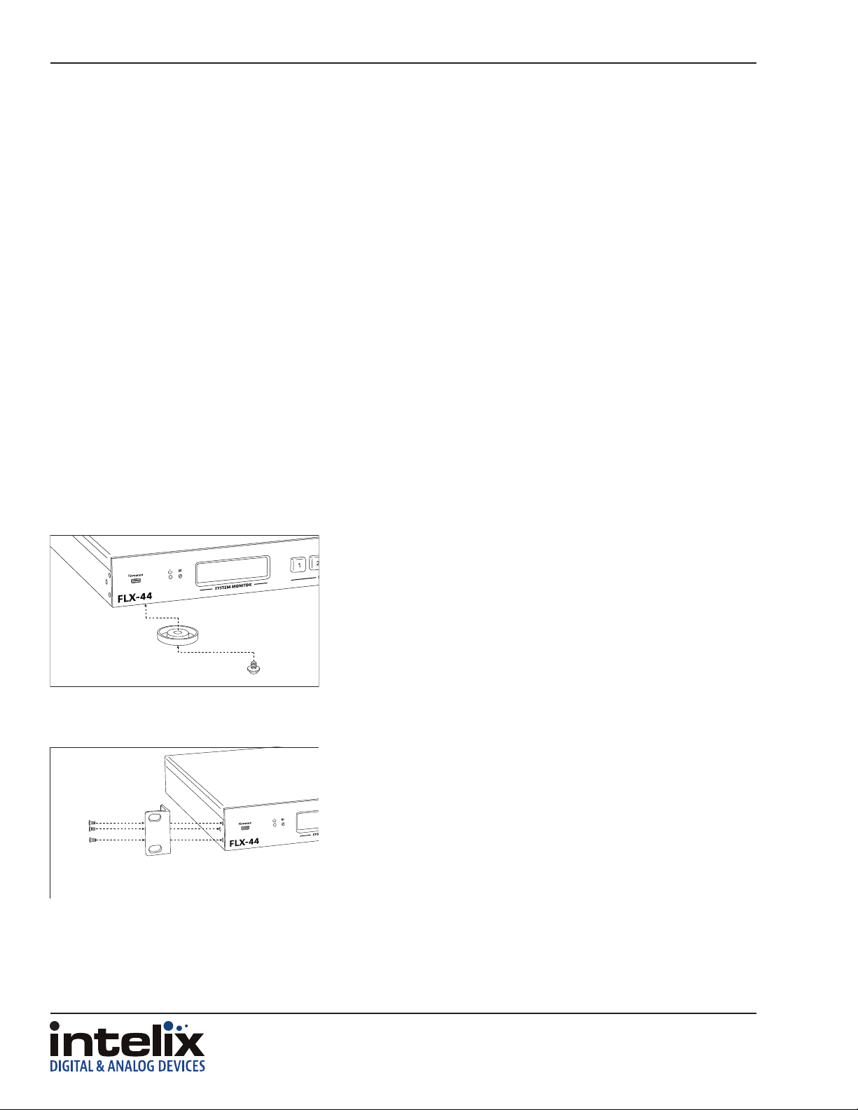
Mount the Matrix
At least 2 inches of free air space is required on both sides of the FLX-44 for proper side venlaon. Avoid mounng
the FLX-44 near a power amplier or any other source of signicant heat.
Shelf Mounng Instrucons
Rack Mounng Instrucons
Aach the supplied shelf feet to the boom of the FLX-44 matrix.
Aach the supplied rack ears to the sides of the FLX-44 matrix. The
matrix requires one rack units (1 RU) of space. It is recommended
that you leave an empty rack space above and below the FLX-44 for
addional cooling.
Connect Ground
A ground screw is located on the boom right rear of the matrix to help eliminate stac shock during installaon
of the matrix. Connect a wire from the matrix to an earth ground.
10

Connect Sources
TIA/EIA-568B
1 8
Connect Displays
HDMI Outputs
FLX-44 Installaon Guide
Connect the source devices to HDMI inputs using HDMI cables that
are less than or equal to 5 meters in length. For source devices that
are further away, an HDMI extension device will be required to
complete the connecon.
HDBaseT Outputs
Pin 1
Pin 2
Pin 3
Pin 4
Pin 5
Pin 6
Pin 7
Pin 8
Orange/White
Orange
Green/White
Blue
Blue/White
Green
Brown/White
Brown
Connect the display devices to HDMI outputs using HDMI cables
that are less than or equal to 5 meters in length. For display devices
that are further away, it is highly recommended to ulize the
HDBaseT outputs.
For all HDBaseT cabling, the EIA/TIA-568B crimp paern must be
used on Category 6 or greater cable. In areas with large amounts
of electromagnec (EM) or radio frequency (RF) interference, a
shielded variety of Category 5e or greater cable is recommended
with shielded connectors on both ends of the selected cable.
The HDBaseT outputs provide 15 was of Power over Ethernet,
which eliminates the need for a power supply with a compable
HDBaseT receiver. Intelix recommends using the DIGI-HD60C-R for
installaons which require remote power.
Connect the HDBaseT receiver to the display per the manufacturer’s
instrucons. Connect the HDBaseT cable to the matrix and the
HDBaseT receiver.
11

FLX-44 Installaon Guide
Connect Audio Outputs
L
L+
L-
R-
If the analog audio outputs are to be used in the installaon, connect
the Le, Right, and ground reference wires to the removable 3-pole
terminal block.
R
R+
Insert the removable 3-pole terminal block to the appropriate
output zone terminal.
Connect IR Control
The FLX-44 has an advanced bidireconal IR control protocol through the HDBaseT output port, which allows for
the control of the sources, displays, and matrix. Intelix recommends using the DIGI-HD60C-R for installaons which
require IR extension.
Only use DIGIB-EMT (IR transmier) and DIGIB-EYE (IR receiver), which are sold separately, with the FLX-44. Third
party 12V DC IR components are not compable with the FLX-44.
Source Device and Matrix Control via Remote IR
An IR signal passed from the display locaon through the HDBaseT connecon can provide control of the source
device. The IR signal from the remote display locaon can also control the switching of the matrix.
Aach the plasc end of the DIGIB-EMT to the IR receiver of the
source device. Insert the TS 3.5 mm plug of the DIGIB-EMT to the IR
output port (IR OUT) of the matrix for the source device to control.
12

FLX-44 Installaon Guide
Remote Display Control via IR
An IR signal may be passed to a remote display locaon through the HDBaseT connecon. There are two possible
IR input connecons for controlling a remote display: IR In for an individual output zone and IR All In for global IR
signal distribuon.
Zone Control via IR
Insert the TRS 3.5 mm plug of the DIGIB-EYE to the IR input port
(IR IN) of the matrix for the output zone of the display device to
control.
Global Control via IR
Insert the TRS 3.5 mm plug of the DIGIB-EYE to the global IR input
port (IR ALL IN) of the matrix to control all remote display devices.
Concealed Matrix Control via IR
When the FLX-44 is installed in an equipment rack or other concealed locaon, access to the front panel for normal
IR control may be dicult. The IR EYE input allows the IR remote to control the matrix via a connected DIGIB-EYE.
Insert the TRS 3.5 mm plug of the DIGIB-EYE to the matrix IR input
port (IR EYE) of the matrix.
13

FLX-44 Installaon Guide
Connect RS232 Control
In addion to tradional RS232 control, the FLX-44 has an advanced RS232 control mechanism which allows RS232
tunneling and roung through the HDBaseT output port to control remote devices. Intelix recommends using the
DIGI-HD60C-R for installaons which require RS232 extension.
See page 27 for all available control commands for the FLX-44.
Matrix Control via RS232
The RS232 control port requires a standard straight-through serial cable for operaon. The default sengs for the
RS232 port are:
• 9600 baud
• 8 Data Bits
• 1 Stop Bit
• Parity = none
Connect a standard straight-through serial cable with DE9 connector
between the RS232 port on the FLX-44 and the controller.
Remote RS232 Control via Tunneling
Discrete remote control of remote display devices is possible by connecng an RS232 output of a control system
to the 3-pole terminal block on the output of the matrix. A compable HDBaseT with control receiver is required
to pass the control signals to the display devices.
To use the RS232 extension capabilies of the FLX-44, connect the TX, ground, and RX control signal wires to the
removable 3-pole terminal block. Consult the manual of the control device(s) to determine which pins the TX/RX
signals are carried on. Be sure to always connect TX to RX and RX to TX.
RXD
FLX-44Controller
Tx
DIGI-HD60C-R Display
Rx
TXD
14
GND
TXD
Rx
Tx
GND
RXD

FLX-44 Installaon Guide
Insert the removable three-pole terminal block into the
RS232 tunneling port for the output zone which requires remote
RS232 control.
Remote RS232 Control via RS232 Roung
The FLX-44 has the logic to pass RS232 commands to remote devices through the DE9 RS232 port. Please see page
29 for more informaon on how to implement this feature in an installaon.
15

FLX-44 Installaon Guide
1 8
Connect TCP/IP (Ethernet) Control
The FLX-44 may be controlled via Ethernet with a third party control system or through a web browser interface.
Addionally, the FLX-44 has an advanced RS232 control mechanism which will transmit RS232 commands through
the HDBaseT output port to control remote devices with a simple command string. Intelix recommends using the
DIGI-HD60C-R for installaons which require RS232 extension.
See page 27 for all available control commands for the FLX-44.
The TCP/IP port requires a standard straight-through Category 5 or
TIA/EIA-568B
Pin 1
Pin 2
Pin 3
Pin 4
Pin 5
Pin 6
Pin 7
Pin 8
Orange/White
Orange
Green/White
Blue
Blue/White
Green
Brown/White
Brown
greater cable with the TIA/EIA-568B crimp paern for operaon.
The default sengs for the TCP/IP port are:
IP address: 192.168.0.178
Port: 8080
Matrix Control via TCP/IP (Ethernet)
Connect the Ethernet cable between to the matrix and a router with
a straight-through cable or between the matrix and a computer
with a crossover cable.
Router Connecon
1. Congure the router to use the same IP range as the matrix, such as 192.168.0.1.
2. Connect the computer to the router.
3. Connect the FLX-44 to the router
16

FLX-44 Installaon Guide
Crossover Cable Connecon
1. Congure the computer to use the same network prex as the IP address assigned to the matrix. For example,
the IP address of the matrix is 192.168.0.178. Set the computer to use a stac IP address within the same
network range, such as 192.168.0.42.
2. Connect the network crossover cable to the computer and to the TCP/IP port on the FLX-44.
Crossover Cable Pinout
1 8
Pin 1
Pin 2
Pin 3
Pin 4
Pin 5
Pin 6
Pin 7
Pin 8
TIA/EIA-568A
Green/White
Green
Orange/White
Blue
Blue/White
Orange
Brown/White
Brown
1 8
Pin 1
Pin 2
Pin 3
Pin 4
Pin 5
Pin 6
Pin 7
Pin 8
TIA/EIA-568B
Orange/White
Orange
Green/White
Blue
Blue/White
Green
Brown/White
Brown
Web Browser Control
The FLX-44 includes a web portal to allow control of the matrix via a standard web browser. The IP address is the
same address that is used for TCP/IP control. See page 21 for detailed informaon regarding the web browser
interface, including customizaon.
Remote RS232 Control via TCP/IP Roung
The FLX-44 has the logic to pass RS232 commands to remote devices through the TCP/IP port. Please see page
29 for more informaon on how to implement this feature in an installaon.
17

FLX-44 Installaon Guide
Apply Power
Plug the power supply into the power input port on the rear
of the matrix.
Connect the IEC power cable into the power supply. The matrix will
turn on once the IEC cable is plugged into AC power.
LCD Panel Boot-up Informaon
While the matrix is boong up, the front LCD panel will show the IP address of the matrix and the current version
of rmware. Aer ve seconds, it will show Intelix FLX-44. The backlight will go dark aer ve seconds.
See page 23 on how to customize the informaon displayed on the LCD panel.
18

FLX-44 Installaon Guide
Front Panel and IR Remote Operaon
Basic Roung
To set a route using the front panel of the FLX-44:
1. Press the desired input buon (source).
2. Press the desired output buon (display).
3. Press the TAKE buon. All the selected buons will ash then go dark indicang a roung change.
To route video and audio from input 2 to output 4:
Press input 2.
Press output 3.
Press TAKE.
Advanced Roung
To route video and audio from input 3 to all outputs:
1. Press input 3.
2. Press outputs 1, 2, 3, and 4.
3. Press TAKE.
19

FLX-44 Installaon Guide
IR Remote Operaon
The buons on the IR remote are idencal to the buons on the front panel of the FLX-44. The IR roung command
sequences are idencal to the front panel command sequences.
The Standby buon will send the matrix to a low power state. Pressing the Standby buon a second me will
restore the FLX-44 to full power.
20

End User Login
FLX-44 Installaon Guide
Web Browser Control
Open a web browser and go to the IP address of the FLX-44. The
default IP address is 192.168.0.178.
Select User from the UserName drop-down.
Matrix Control
Enter the password to gain control of the matrix. The default password
is “123456”.
Press the Enter key on your keyboard or tablet to go to the matrix
control screen.
Click the input to output route and the buon will turn green once
the route has been changed.
21

FLX-44 Installaon Guide
Administrator Login
Open a web browser and go to the IP address of the FLX-44. The
default IP address is 192.168.0.178.
Select Administrator from the UserName drop-down.
Matrix Control and Setup Access
Enter the password to gain control of the matrix. The default password
is “admin”.
Press the Enter key on your keyboard or tablet to go to the matrix
control screen.
Click the input to output route and the buon will turn green once
the route has been changed.
Click the Setup buon in the top right corner of the matrix control
screen to access the administrave controls.
22

FLX-44 Installaon Guide
Web Browser Customizaon
When changes are made on a setup tab, the Save buon must be pressed for the changes to take eect.
Users Tab
The Users setup screen provides opons to change the Administrator and User passwords. The front panel can also
be locked to prevent tampering from this screen.
Interface Tab
The Interface setup screen features opons to customize the end user’s experience with the matrix.
» Title Bar Label
◊ This changes the tle that is shown on the Matrix Control screen.
» LCD Readout
◊ The LCD panel can be customized with a limit of 16 characters per line.
◊ Apostrophe (’), comma (,), and backslash (\) are not supported characters.
» Buon Labels
◊ Input and output labels can be changed to make roung signals easier for the end user.
23

FLX-44 Installaon Guide
HDCP and EDID Conguraon Tab
The Conguraon setup screen has opons to turn on and o the HDCP compliance ag for an input, which is ideal
for laptops with signals going to a video conferencing system.
The EDID from a display can be copied to an input. A Full copy will copy all the video and audio capabilies of the
display. A Hybrid copy will copy the video capabilies of the display and specify PCM two channel audio, which is
ideal when using the analog audio outputs.
Aer the “EDID copy mode”, “output to copy from”, and “input to copy to” are selected, click the Go! buon. You
will be presented with an EDID copy success window aer the changes are successfully applied to the matrix.
24

FLX-44 Installaon Guide
Network Tab (IP Address)
The Network setup screen features DHCP or Stac IP sengs for the matrix. This screen also shows the current
version of soware in the matrix.
25

FLX-44 Installaon Guide
EDID Management
The stock EDID for the inputs of the FLX-44 is 1280x1024 (computer video input) and 1080p with stereo audio
(consumer video input). In order to change the EDID informaon for an input, the EDID copy command will need
to be sent to the matrix via RS232 or TCP/IP or managed through the web browser setup interface (see page 24).
EDIDMyyBxx.
EDIDHyyBxx.
EDIDMInit.
Copy video and audio EDID of output yy to input xx
Copy video EDID of output yy and specify 2 channel PCM to input xx
Restore factory EDID informaon
Full EDID Copy
To copy the video and audio EDID informaon from output 3 to input 1, transmit the following command:
EDIDM03B01.
Hybrid EDID Copy
Hybrid EDID copy is the preferred command to use when the audio is going to be routed to an analog audio output
of the matrix. To copy the video EDID informaon from output 2 and specify two channel PCM audio output to
input 4, transmit the following command:
EDIDH02B04.
26

FLX-44 Installaon Guide
RS232 and TCP/IP Commands
RS232 Sengs: 9600 baud, 8 Data bits, 1 Stop bit, Parity = None
TCP/IP Sengs: User dened IP address (default IP address: 192.168.0.178), port 8080
There is either a period (.) or a semicolon (;) at the end of each command. These characters must be present for
the command to process correctly.
There are no spaces between any of the characters in the command string.
xx = Input Number (input 2 would be 02)
yy = Output Number (output 3 would be 03)
<CR> = Carriage return (Hex 0D)
<LF> = Line Feed (Hex 0A)
Roung Commands
Descripon Command Response
Route input xx to output yy
Route input xx to all outputs
Route inputs to corresponding outputs
Route input xx to mulple outputs yy
Number of outputs is unlimited; each
output must be separated by a comma (,)
Turn o all outputs
Turn o specic output yy
Output yy roung status
Roung status of all inputs.
Examples:
xxByy. AV: xx->0yy<CR><LF>
xxAll. xx To All<CR><LF>
All#. All Through.<CR><LF>
xxByy,yy. xxVyy,yy<CR><LF>
All$. All Closed.<CR><LF>
yy$. AV: yy Closed. <CR><LF>
Statusyy. V: xx->0yy<CR><LF>
Status.
V: xx->0yy<CR><LF>
(Repeang sequence starng with
output 1, output 2, etc�)
02All.
04$.
02B03.
03B02,04.
Route Video and Audio from input 2 to all outputs
Turn o Video and Audio for output 4
Route Video and Audio from input 2 to output 3
Route Video and Audio from input 3 to outputs 2 and 4
27

FLX-44 Installaon Guide
Preset Commands
Descripon Command Response
Save the current roung as a preset. Values
range from 0 through 9
Recall preset x
Clear preset x
Examples:
Savex. Save to Fx<CR><LF>
Recallx. Recall From Fx<CR><LF>
Clearx.
Save4.
Recall4.
Clear4.
Save the current roung as preset 4.
Recall preset 4
Clear preset 4
System Commands
Descripon Command Response
Power full ON
Power o (Standby Mode)
Retrieve matrix model informaon
Lock the front panel keys
Unlock the front panel keys
Retrieve matrix rmware version number
Turn o matrix command feedback
Turn on matrix command feedback
PWON. PWON<CR><LF>
PWOFF. PWOFF<CR><LF>
/*Type; FLX-44<CR><LF>
/%Lock; System Locked!<CR><LF>
/%Unlock; System Unlock!<CR><LF>
/^Version; Vz.z<CR><LF>
/:MessageOff; Closed the Message
Return.<CR><LF>
/:MessageOn; Enabled the Message
Return.<CR><LF>
EDID Commands
Descripon Command Response
Copy EDID of output yy to input xx
Copy Hybrid EDID of output yy to input xx
Restore factory EDID informaon
Example:
EDIDM02B01.
28
Copy EDID of output 2 to input 1
EDIDMyyBxx. EDIDMyyBxx.<CR><LF>
EDIDHyyBxx. EDIDHyyBxx.<CR><LF>
EDIDMInit. EDIDMInit<CR><LF>

HDCP Commands
Descripon Command Response
Turn HDCP Compliance o for input xx
Turn HDCP Compliance on for input xx
Example:
/%I/xx:0. /%I/xx:0.<CR><LF>
/%I/xx:1. /%I/xx:1.<CR><LF>
FLX-44 Installaon Guide
/%I/04:0.
Turn HDCP Compliance o for input 4
Remote RS232 Control via Roung
The FLX-44 has the logic to pass RS232 commands to remote devices through the TCP/IP or DE9 RS232 ports. The
desnaon command string is embedded in a command which includes the desnaon HDBaseT output port and
baud rate. This is a bidireconal communicaon method. The maximum string length is 48 bytes (characters). In
addion to immediate transmission, the FLX-44 can store commands to be broadcast when the matrix is powered
on or o through the standby commands (PWON. and PWOFF.).
The format of the RS232 roung string is: /+<Y>/<B>:<$>. (The period at the end of the string is required.)
<Y> is the output code, <B> is the baud rate, and <$> is the RS232 string. Output codes and baud rate codes are
in the tables below.
Output Code Timing
1 Immediate TX
1
2
3
4
ALL 5 Immediate TX
A PWON command
E PWOFF command
2 Immediate TX
B PWON command
F PWOFF command
3 Immediate TX
C PWON command
G PWOFF command
4 Immediate TX
D PWON command
H PWOFF command
Baud Baud Code
2400 1
4800 2
9600 3
19200 4
38400 5
57600 6
115200 7
Examples:
/C+/4:PowerOn.
/C+/4:.
Send the string PowerOn to output 3 at 19200 baud when the matrix is powered
on.
Clear power on seng for output 3.
29

FLX-44 Installaon Guide
Troubleshoong
Matrix does not power on
» Verify power outlet is acve.
» Verify connuity in power cable.
Cannot view 3D content
» Copy EDID from output to input.
» Verify display is 3D compable.
» Verify source device can output 3D content.
» Verify twisted pair cable does not exceed 40 meters.
Cannot hear surround sound audio
» Copy EDID from output to input.
» Verify output can broadcast surround sound audio.
» Verify source device is congured to output surround sound audio.
No video from HDBaseT output
» Verify the amber link LED on the HDBaseT output is lit solid.
Amber LED
30

FLX-44 Installaon Guide
Technical Specicaons
I/O Connecons
HDMI Inputs Four (4) HDMI Type A Receptacle (1 per input)
HDMI Outputs Two (2) HDMI Type A Receptacle (Outputs 1 and 2 only)
HDBaseT Outputs Four (4) 8P8C port (Shielded RJ45) (1 per output)
IR Inputs Four (4) 3.5 mm jack (TRS)
IR All In One (1) 3.5 mm jack (TRS)
IR Outputs Four (4) 3.5 mm jack (TS) (1 per output)
IR Eye One (1) 3.5 mm jack (TRS)
RS232 Tunnel Four (4) 3-pole Removable Euroblock Connector (3.5mm)
Audio Outputs Four (4) 3-pole Removable Euroblock Connector (3.5mm)
48V DC Power One (1) Amphenol 4pin CPC Female (11-4)
Control, Rear Panel RS232 via DE-9, TCP/IP via 8P8C, IR via 3.5mm TRS
Control, Front Panel Push Buon, IR
Supported Audio, Video and Control
Maximum Video Compability at 60 m Deep Color 36/30/24 Bit at 1080p
Maximum Video Compability at 35 m Deep Color 48 Bit at 1080p, 3D, and 4k x 2k
Supported 3D Formats Field Alternave (interlaced), Frame Packing, Line Alternave Full, Side-By-Side Half, Side-
Embedded Audio Compability Up to PCM 5 channel, Dolby Digital TrueHD, and DTS-HD Master Audio
IR Carrier Frequency Range 33-55kHz at 5 volts
RS232 Baud Rate Up to 115200 baud
HDBaseT Signal Characteriscs
Maximum Distance 70m (230 )
Cable Requirements Solid core shielded Category 5e, Category 6 or greater with TIA/EIA-568B crimp paern
Bandwidth 10.2 Gbps
Gain 0 dB – 10 dB at 100 MHz
Signal to Noise Rao (SNR) > 70 dB at 100 MHz over 100 m
Return Loss < -30 dB at 5 KHz
Total Harmonic Distoron (THD) < 0.005% at 1 KHz
Min-Max Signal Level < 0.3 V – 1.45 Vp-p
Dierenal Phase Error ±10° at 135 MHz over 100 m
Chassis and Environmental
Enclosure Painted Aluminum
Dimensions 435 mm x 235 mm x 44 mm (17.13 in x 9.25 in x 1.73 in)
Rack Spacing 1 RU
Shipping Weight 2.27 kg (5 lbs)
Operang Temperature 0° to +40° C (+32° to +104° F)
Operang Humidity 20% to 90%, Non-condensing
Storage Temperature -10° to +60° C (+14° to +140° F)
Storage Humidity 20% to 90%, Non-condensing
Power, ESD, and Regulatory
Power Supply Input 100V-240VAC / 1.8A
Power Supply Output 48vDC / 5A
Power Consumpon 150 was (max)
ESD Protecon 15kV
Device Regulatory CE, RoHS
Power Supply Regulatory UL, FCC, CCC, CE, RoHS
Other
Warranty 2 years
Diagnosc Indicators LCD output status and power LED
Included Accessories Installaon Guide, IR Remote, RS232 cable, US Power Cable and Power Supply, Two
Compable IR Transmier (IR Emier) DIGIB-EMT
Compable IR Receiver (IR Eye) DIGIB-EYE
Compable Receivers (AV Only) DIGI-HD70-R
Compable Receivers (AV and Control) DIGI-HDE-R
Compable Receivers (AV, Control and Power) DIGI-HD60C-R
By-Side Full, 2D + Depth, 2D + Depth + Graphics + Depth
Mounng Brackets with screws, Four Rack Feet with screws, Eight 3-pole Removable
Euroblock Connectors (installed on matrix)
Distances and picture quality may be aected by cable grade, cable quality, source and desnaon equipment, RF and electrical interference, and cable patches.
31

Thank you for your purchase.
Please contact us with your quesons and comments.
Intelix
8001 Terrace Ave, Ste 201
Middleton, WI 53562
Phone: 608-831-0880
Toll Free: 866-462-8649
Fax: 608-831-1833
www.intelix.com
intelix@intelix.com
Intelix is a brand of:
11675 Ridgeline Drive
Colorado Springs, Colorado
80921 USA
Phone: 719-260-0061
Fax: 719-260-0075
Toll-Free: 800-530-8998
 Loading...