

Page 1
8001 Terrace Ave
Suite 201
Middleton, WI 53562
Phone: 608-831-0880
Toll-Free: 866-4-MATMIX
Fax: 608-831-1833
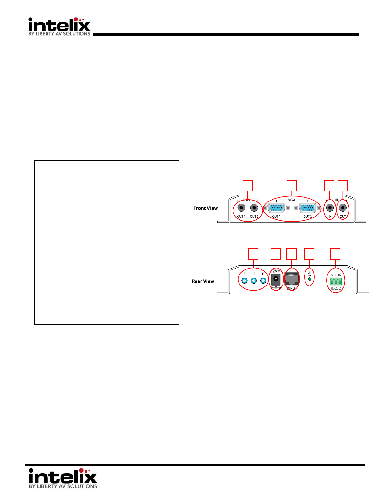
Connector Descriptions:
1. Stereo Audio Outputs – [2] Stereo Audio Outputs (line
level) are simultaneously active when signal is connected
to a compatible transmitter. Video signal is not required
for audio to pass.
2. VGA Outputs – [2] VGA Outputs are simultaneously active
when signal is connected to a compatible transmitter.
3. IR IN – Connect a VGASD2-EYE (not included) to this port.
The IR eye will send IR information back to the compatible
transmitter for the purpose of controlling the source with
the OEM remote.
4. IR OUT – Connect a VGASD2-EMT (not included) to this
port. IR information sent from the compatible transmitter
will be emitted for the purpose of controlling the display
with the OEM remote (place the emitter over the display’s
IR window).
5. RGB Trim – Picture level adjustment. Use a small
screwdriver to fine tune the image to satisfaction.
6. Power inlet – Connect the (included) 12vDC, 2A power
supply.
7. Twisted Pair Input – Connect this to the compatible
transmitter using Cat5e (or equivalent) cable.
8. Power LED – Lit when unit is ON.
9. RS232 Pass-through – This connection allows RS232
commands to be passed through the extenders. Connect a
control system to either end, and control the remote
source or display.
5
6 7 8
9
The Intelix DIGI-VGASD2-R receives computer video, stereo audio, and control signals over a single twisted pair cable, such as
Cat 5e or Cat 6.
The DIGI-VGASD2-R features dual amplified outputs and adjustable video equalization.
The DIGI-VGASD2-S features up to 1920x1200 computer video performance and high-fidelity 20Hz to 20kHz audio performance
extension up to 350 feet. The DIGI-VGASD2-S features bi-directional IR and RS232 extension up to 350 feet.
Installation Instructions:
1. Install units securely using attached mounting ears.
2. Set DIP switches to desired mode on the transmitter (DIGI-VGASD2-S/T4/T8)
3. Connect twisted pair cable between the transmitter (DIGI-VGASD-S/T4/T8) and the receiver (DIGI-VGASD2-R). Ensure T568B straight-
thru wiring.
4. Connect VGA, audio, and control cables between the display and the receiver (DIGI-VGASD2-R). Connect ONLY IR or RS232.
5. Connect VGA, audio, and control cables between the source and the transmitter (DIGI-VGASD2-S). Connect ONLY IR or RS232.
6. Connect the included power supplies to the transmitter and receiver.
7. Power on attached audio/video devices.
8. Adjust trim pots on the receiver until color levels in the image are equal and any video “streaking” is not visible in the image. Start with
Green, then Red, then Blue. *An empty Excel spreadsheet is recommended for content – adjust levels until the cell outlines are visible,
and the cells are white.
DIGI-VGASD2-R Installation Guide
DIGI-VGASD2-R Installation Guide
VGA, Audio, & RS232/IR over Twisted Pair Receiver
Rev. 120821
Page 2
DIGI-VGASD2-R Installation Guide
8001 Terrace Ave
Suite 201
Middleton, WI 53562
Phone: 608-831-0880
Toll-Free: 866-4-MATMIX
Fax: 608-831-1833
Technical Specifications
Compatible Transmitters
DIGI-VGASD2-S, DIGI-VGASD2-T4, DIGI-VGASD2-T8
Maximum Distance per Linked Unit
350 feet
Supported Video Resolutions
Up to 1920x1200
Supported Audio
Analog stereo audio (-10dBv)
Video Bandwidth
300 MHz
Audio Frequency Response
20 Hz to 20 kHz +/- 1dB
Crosstalk
-70 dB @ 2 kHz with a +7 dB input
-65 dB @ 20 kHz with a +7 dB input
Signal to Noise Ratio
80 dB @ 7 dBu
Required Cabling
Cat 5, Cat 5e, Cat 6, Cat 7 compatible
Unshielded Twisted Pair Maximum
Capacitance
20 pf/foot
Cable Impedance
100 ohms @ 1 MHz (24 gauge or lower solid)
Cable Attenuation
6.6 dB/1000 feet @ 1 MHz copper
Connectors
(2) Computer video outputs (HD15F)
(2) Stereo audio outputs (3.5mm TRS)
(1) IR input (3.5mm TRS)
(1) IR output (3.5mm TS)
(1) Twisted pair input (RJ45)
(1) RS232 input (3 pole euroblock)
(1) Power input (5.5mm coaxial power connector)
Video Adjustment
(1) Red level trim pot
(1) Blue level trim pot
(1) Green level trim pot
Enclosure
Aluminum (Painted Black)
Dimensions (including connectors)
162mm x 95mm x 30mm (6-3/8” x 3-7/8” x 1-3/16”)
Shipping Weight
1.25lbs. (0.57kg)
Power
12vDC 2A
Regulatory
CE, RoHS
ESD Protection
Yes
Diagnostic Indicators
Power LED
Warranty
2 years
What’s in the Box
(1) DIGI-VGASD2-R
(1) 12vDC 2A Power Supply
(1) Installation Manual
Available Accessories (not included)
VGASD2-EYE – IR Receiver
VGASD2-EMT – IR Emitter
Distances, picture and audio quality may be affected by cable
grade, cable quality, source and destination equipment, RF and
electrical.
Important notice:
Do not attempt to disassemble or alter
the extender housing. There are no userserviceable parts inside the unit. Doing so
will void your warranty.
To minimize the possibility of equipment
damage from electrostatic discharge
(ESD), all source and destination
equipment must be powered off during
installation.
Do not connect the extender to a
telecommunication outlet wired to
unrelated equipment. Doing so may
damage the unit or any connected
equipment. Ensure all connected twisted
pair cabling is straight-through (point-topoint).
Allow proper ventilation to reduce the
risk of thermal failure.
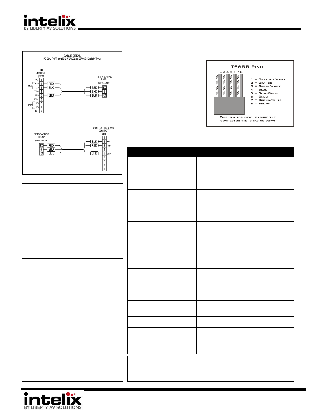
Twisted Pair
Wiring - Use
T568B wiring
for Cat5e/6
connection
between send
and receive
units.
RS232 Wiring:
Consult the
manual of the
control devices
to determine
which pins the
TX/RX signal is
carried on. Be
sure to ALWAYS
connect TX to RX
and RX to TX.
Troubleshooting tips:
1. Noisy Audio – Increase the
source volume
2. Horizontal scrolling video bars –
Ground loop problem - try lifting
or grounding the transmitter or
receiver (VGA capture nut is a
ground)
3. No video – Perform EDID copy on
transmitter, check Cat5 cable,
check source settings (is it on?)
Cable Pinouts:
 Loading...