

Page 1
Frequently Asked Questions
How do I expose the individual pairs in Cat 5 cabling?
There is no single method when exposing the four individual pairs in twisted pair cabling, such
as Cat 5 and Cat 6; however, it does help to have a cable stripping tool designed to strip the
cable jacket/insulation.
Begin by stripping back the cable’s outer jacket/insulation about an inch (or more depending
on whether multiple baluns will be connected to the pairs of a single cable) so that the internal
wires are exposed. Be careful not to cut the internal wires when stripping the insulation/
jacket. Eight twisted wires and a string should now be visible; the string is unnecessary and may
be removed. These eight wires, which when combined form four pairs, connect directly to the
baluns. Typical protocol pairs similar colors; the important thing is to verify the same colorcoded pairs are used on each end.
Intelix DIGI-VGA-F VGA and Audio over Cat 5 Balun Set
Installation ManualInstallation Manual
Installation Manual
Installation ManualInstallation Manual
The Intelix DIGI-VGA-F balun set transmits high-definition VGA video and high-fidelity
analog audio extended distances over inexpensive structured pair cabling, such as Cat 5 and
Cat 6. The DIGI-VGA-F balun set includes a DIGI-VGA-S-F send balun, a DIGI-VGAR-F receive balun, two power supplies, and a USB power cable. The kit is powered on
both the send and receive end with either 12 VDC power supplies or optional USB power
on the send end. The send balun provides a local audio/video outputs for added versatility,
whereas the receive balun features dual amplified audio/video outputs for linking. In
addition, the DIGI-VGA-R-F receive balun provides brightness, contrast, and overall
picture quality adjustment for skew-free performance over standard Cat 5 cabling.
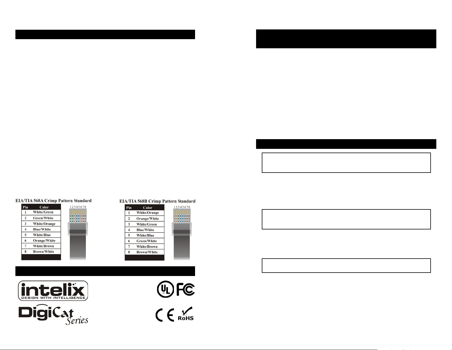
How do I crimp an unshielded RJ45 connector onto Cat 5?
Crimping an RJ45 connector onto Cat 5 is a fairly straight forward task, assuming you have
the proper tools. Keep in mind that baluns require either the EIA/TIA 568A or 568B crimp
pattern, which are the industry standards for networking.
1. First, strip a portion of the insulation about 3/4" to expose the four twisted pairs.
2. Next, untwist the wires and fan them out so that they match either EIA/TIA 568A or
568B pattern.
3. Evenly trim the wires to about 1/2". Most RJ45 crimp tools feature a built-in wire
trimmer.
4. Insert the trimmed wires into the RJ45 connector so that each wire is in its individual
slot. Verify each wire is completely inserted.
5. Finally, insert the RJ45 connector into the crimp tool and squeeze firmly.
6. Repeat the above steps on the other end of the Cat 5 cable and verify pinout is
identical on each end.
Contact Information
Intelix
2222 Pleasant View Road
Middleton, WI 53562
Toll-free: 866-4-MATMIX
Phone: 608-831-0880
Fax: 608-831-1833
www.intelix.com
The Intelix DigiCat Series of baluns is the ideal solution for sending high-performance
audio and video signals over structured cabling. When signal quality matters, choose
Intelix.
Installation
Caution: Do not attempt to disassemble or alter the balun housing. There are
no user-serviceable parts inside the DIGI-VGA-F. Modifying the unit
will void your warranty.
To install a DIGI-VGA-F balun kit, perform the following steps:
1. Turn off power and disconnect the source and destination equipment by following
the device manufacturer’s instructions.
2. Make certain that outlets and cross connects to which you will connect the DIGIVGA-F are configured properly and labeled appropriately to identify the circuit.
Caution: Do not connect the DIGI-VGA-F to a telecommunication outlet wired
to unrelated equipment. Making such a connection may damage the
equipment and/or balun. Please ensure all wiring is “straight-through.”
3. Verify the desired twisted pairs are not being used for other LAN or telephony
equipment.
4. Connect the VGA and audio outputs from the source equipment to the DIGIVGA-S-F send balun. If desired, connect a local monitor and audio outputs.
Caution: Do not mount the balun over equipment ventilation openings. Covering the
openings may cause the equipment to overheat.
5. Connect the VGA and audio inputs from the destination equipment to the DIGIVGA-R-F receive balun.
6. Connect the two baluns with a structured cable with RJ45 connectors, such as
Cat 5. Verify the cable’s pinout conforms to EIA/TIA 568A or 568B pattern
standards.
7. Power on the source and destination equipment and test for correct operation.
8. If required, adjust the brightness and contrast settings on the DIGI-VGA-R-F
receive balun.
Page 2
Specifications
Specifications subject to change without notice.
Maximum Distance* 1920 x 1200 resolution 250 feet
1600 x 1200 resolution 350 feet
1280 x 1024 resolution 500 feet
1024 x 768 resolution 700 feet
800 x 600 resolution 850 feet
Video Bandwidth DIGI-VGA-R-F receive unit (250 feet): 120 MHz
DIGI-VGA-R-F receive unit (850 feet): 50 MHz
DIGI-VGA-S-F send unit: 350 MHz
Input Video Signal 1.2V p-p
Audio Frequency Response 20 Hz to 20 kHz
Audio Impedance 600 ohm
Audio Nominal Level 0-1.0V
Common Mode Rejection 60 dB
Unshielded Twisted Pair Maximum capacitance: 20 pf/foot
Cabling Specifications Impedance: 100 ohms @ 1 MHz
(24 gauge or lower solid Attenuation: 6.6 dB/1000 ft. @ 1 MHz
copper) Cat 5, Cat 5e, Cat 6, Cat 7 compatible
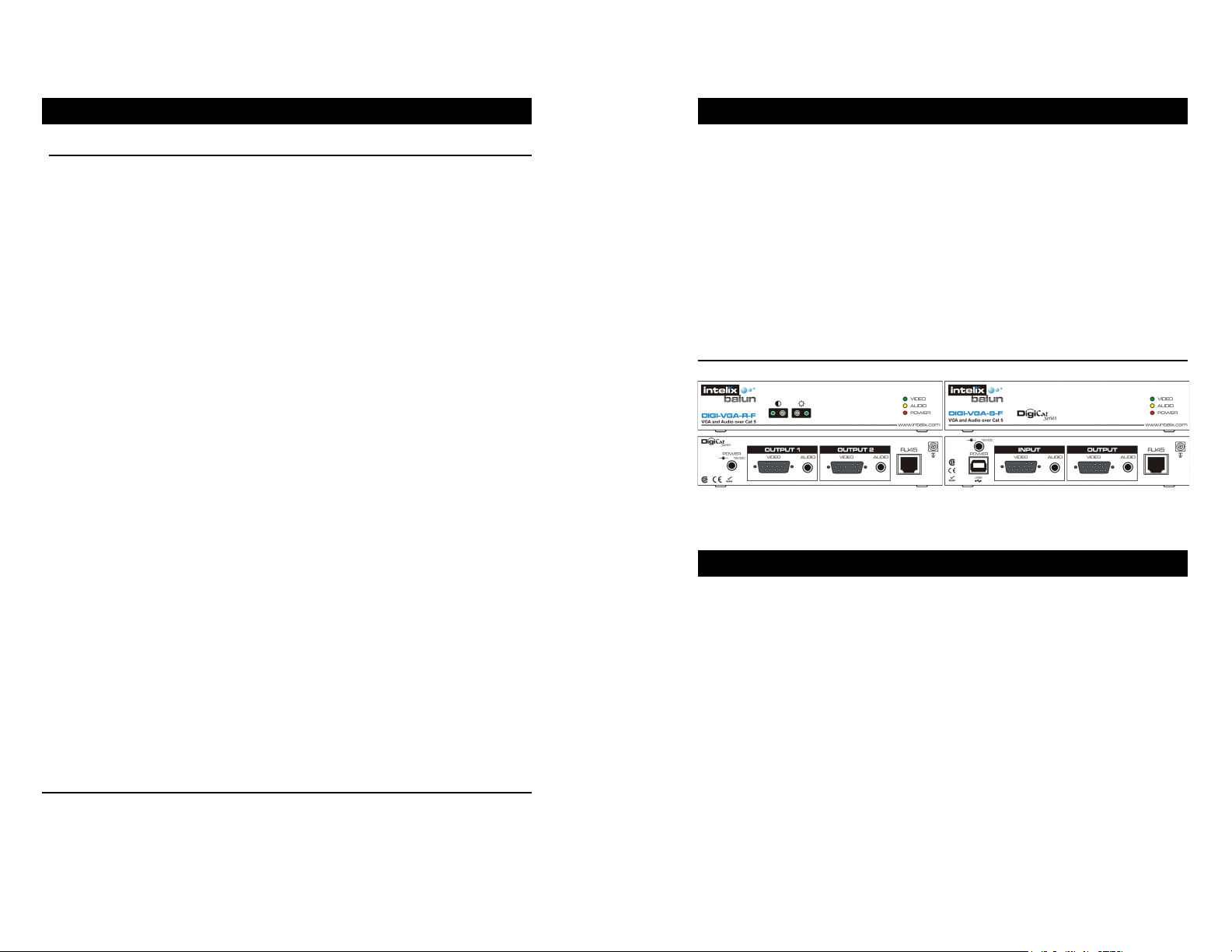
Send Unit Connectors One female HD15 input, one female HD15 output, one 1/8”
mini audio input, one 1/8” mini audio output, one shielded
RJ45 output, one USB type-B power connector, one DIN mini
power connector
Receive Unit Connectors Two female HD15 outputs, two 1/8” mini audio outputs, one
shielded RJ45 input, one DIN mini power connector
Max Units for Linking 3
Max Distance Between Links Distance based on resolution
Temperature Operating: 32 to 131 F (0 to 55 C)
Storage: -4 to 185 F (-20 to 85 C)
Humidity: up to 95%
Power Consumption DIGI-VGA-R-F receive unit: 12V/0.5A or 6W
DIGI-VGA-S-F send unit: 12V/0.2A or 2.4W
Brightness Front panel trim-pot on DIGI-VGA-R-F receive unit
Contrast (skew adj.) Front panel trim-pot on DIGI-VGA-R-F receive unit
Status Front panel video, audio, and power LEDs on both the DIGI-
VGA-R-F receive and DIGI-VGA-S-F send units
* Distances and picture quality may be affected by cable grade, cable quality, source and
destination equipment, RF and electrical interference, and cable patches. Intelix
specifications are based on straight-through cabling with standard-grade Cat 5.
Specifications
Enclosure Metal
Dimensions DIGI-VGA-R-F receive unit: 6.25” x 1.25” x 3.25”
DIGI-VGA-S-F send unit: 6.25” x 1.25” x 3.25”
Shipping Weight DIGI-VGA-F: 4.0 lbs.
Ordering Information DIGI-VGA-F: includes one DIGI-VGA-S-F send balun, one
Warranty 2 years
DIGI-VGA-R-F
Receive Unit
DIGI-VGA-R-F receive balun, two DC power supplies, and
one USB power cable
DIGI-VGA-R-F: includes one DIGI-VGA-R-F receive balun
and one DC power supply
DIGI-VGA-S-F: includes one DIGI-VGA-S-F send balun,
one DC power supply, and one USB power cable
DIGI-VGA-S-F
Send Unit
Troubleshooting
If your equipment malfunctions with DIGI-VGA-F baluns in place, follow the
troubleshooting procedures below:
1. Perform diagnostics on your equipment by following the manufacturer’s
instructions.
2. Check all the connections and the structured cabling system. Verify the RJ45
crimp pattern conforms to either EIA/TIA 568A or 568B standards.
3. Check the pin configuration on the structured cable.
4. The maximum operational distances over which the DIGI-VGA-F balun kit can
be transmitted is dependant on the equipment used and cable. Ensure that the
maximum recommended operational distances have not been exceeded.
5. Check that only twisted pair patch cords are being used.
6. Replace the DIGI-VGA-F balun kit with another DIGI-VGA-F balun kit that is
known to be working.
7. Adjust the brightness and contrast setting on the DIGI-VGA-R-F receive balun.
8. If you still cannot diagnose the problem, contact Intelix for support.
 Loading...