

Page 1
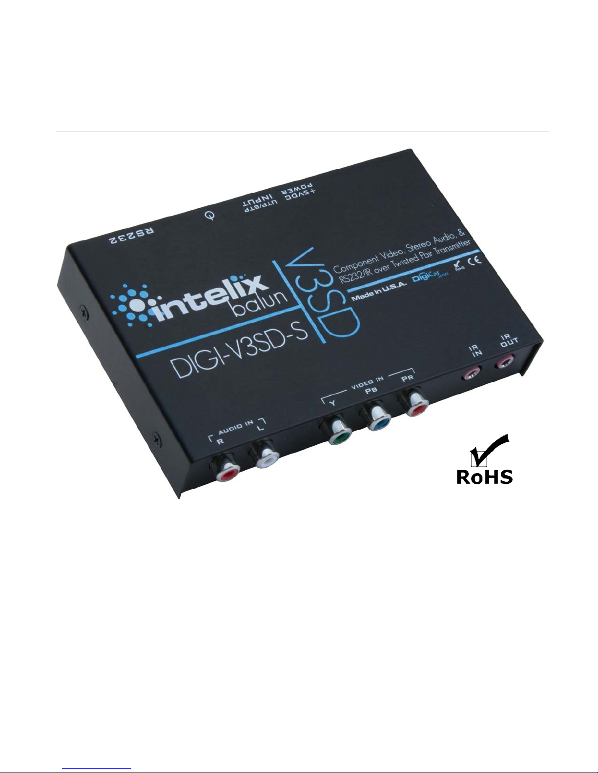
Intelix DIGI-V3SD-S
Installation Manual
Introduction
When used with a compatible receive balun, the Intelix DIGI-V3SD- S active
balun transmits component video (YPbPr), stereo audio, and IR or RS232 up
to 1,000 feet over a single twisted pair cable.
The DIGI-V3SD-S supports 1080i, 720p, 480i, and 480i video and provides
20 Hz to 20 kHz, hi-fidelity audio performance.
The completed system is powered on both the send and receive ends.
Page 2

Installation
To install the Intelix DIGI-V3SD-S balun, perform the following steps:
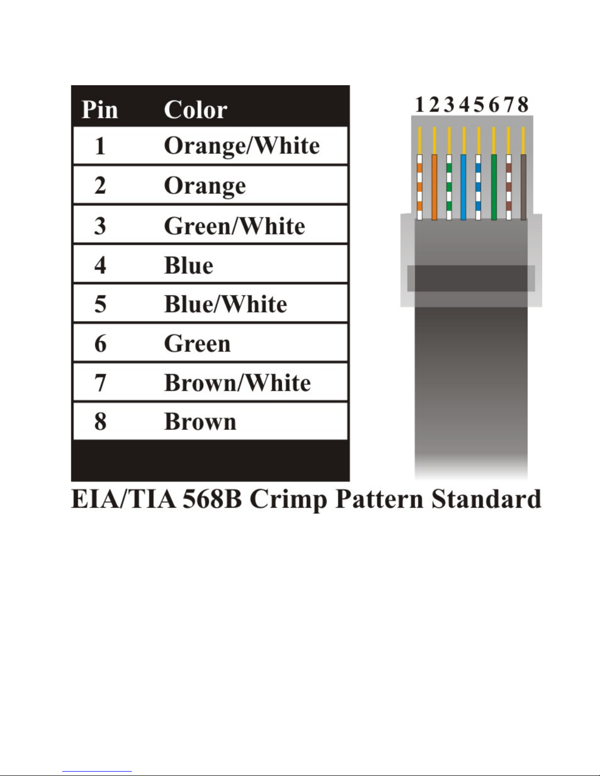
1. Identify the pin configuration of the send balun, compatible receive balun,
and RJ45 connectors on the twisted pair cabling. To eliminate crosstalk,
the pin configuration must follow the EIA/TIA 568B standard. Please
ensure that wiring is straight-through.
2. Power-off the connecting audio, video, and control equipment.
3. Connect the DIGI-V3SD-S send balun to the component video (YPbPr)
output of the video source, the audio output of the audio source, and an IR
or RS232 control source. Do not connect the 5V power supply.
Note the DIGI-V3SD-S does not support IR and RS232
simultaneously.
4. Connect a compatible receive balun (typically a DIGI-V3SD-R) to the
component video (YPbPr) input of the video destination, the audio input of
the audio destination, and an IR or RS232 control destination. Do not
connect the 5V power supply.
5. Complete the connection between the send and receive baluns using one
run of twisted pair cable. Ensure there are no split pairs or taps.
6. Connect the 5V power supply to the send balun.
7. Connect the 5V power supply to the receive balun.
8. Power-on the connecting audio, video, and control equipment.
9. Verify picture quality. If applicable, adjust the signal using the blue, green,
and red dials on the receive balun.
Page 3
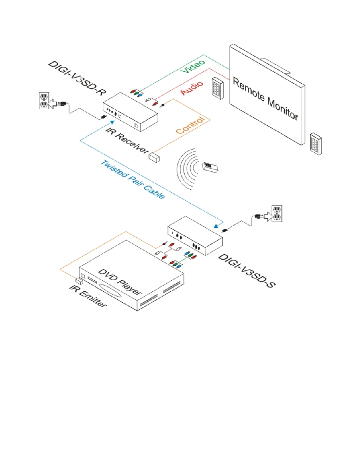
Example System
Page 4
Page 5

Troubleshooting
Symptom Causes Possible Solutions
No signal
No continuity in
video link
No signal Power off
No signal
Improper
connection or
swapped pairs
Verify cable continuity between pairs of
baluns.
Verify the max distance has not been
exceeded.
Verify the audio, video, and control
cables between the equipment and
hardware are connected and pass signal.
Check power supplies of video
equipment.
Verify the LEDs on both the send and
receive units are illuminated.
Check that baluns are connected to
correct video inputs and outputs.
Verify both ends of the twisted pair
cable conform to the EIA 568B crimp
pattern.
Unusual colors
Rolling signal
Horizontal
video bars
No control
Background
pattern
Improper
grounding or
cable type
Simultaneous
RS232 and IR
EMI interference
Verify the source and destination
devices are grounded. Different
electrical circuits may cause a voltage
differential on the building’s electrical
ground plain. The video display or
source device may need to be grounded.
Verify only IR or RS232 are being used.
Identify possible radiating frequency
sources (i.e.; wireless LANs, switching
power supplies) and isolate them.
Replace any unshielded twisted pair
cable with shielded twisted pair cable.
Page 6

Technical Specifications
Video Bandwidth 300 MHz
Supported Signals YPbPr, Y/C, composite video, stereo audio,
IR, RS232
Max Distance 1,000 feet
Audio Frequency Response 20 Hz to 20 kHz
Enclosure Metal
Control IR or bi-directional RS232
Max Distance of AV Cables 6 feet
Status Front panel power LED
Power 5 VDC
Dimensions 5.25” x 3.38” x 1.00”
Temperature Operating: 0° to 55°C
Storage: -20° to 85°C
Humidity: up to 95%
Shipping Weight 5.0 lbs.
Warranty 2 years
Compliancy CE, RoHS
Included Accessories One (1) send balun (DIGI-V3SD-S) and one
(1) 5VDC power supply
Ordering Information DIGI-V3SD-S
*Distances, picture and audio quality may be affected by cable grade,
cable quality, source and destination equipment, RF and electrical
interference, and cable patches. Intelix specifications are based on
straight-through cabling with standard-grade Cat 5.
Page 7

Intelix LLC
2222 Pleasant View Road Phone: 608-831-0880
Middleton, WI 53562 Toll-Free: 866-4-MATMIX
www.intelix.com [email protected]
Page 8

 Loading...