

Page 1
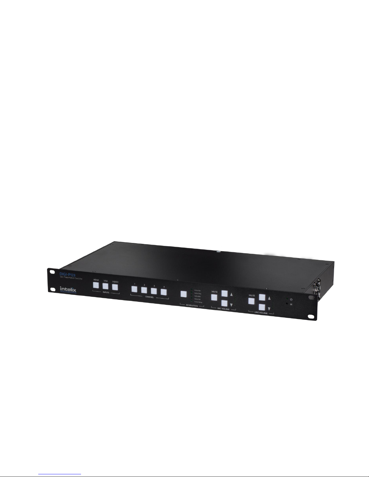
DIGI-P122/P123 Installation and
Operation Guide
Rev 131113 8001 Terrace Ave Phone: 608-831-0880
Suite 201 Toll-Free: 866-462-8649
Middleton, WI 53562 Fax: 608-831-1833
Page 2
DIGI-P122 / DIGI-P123 Installation Guide
Important Safety Instructions
Please make sure you have read and completely understand all instructions in this manual before operating this
equipment.
Keep these instructions in a safe, accessible place for future reference.
Heed all warnings.
Follow all instructions.
Do not use this apparatus near water.
Clean only with a dry cloth.
Do not install near any heat sources such as radiators, heat registers, stoves, or other apparatus (including amplifiers)
that produce heat.
Use only accessories specified or recommended by Intelix.
Explanation of graphical symbols:
o Lightning bolt/flash symbol: the lightning bolt/flash and arrowhead within an equilateral triangle symbol is
intended to alerttheuser to the presence of uninsulated “dangerousvoltage”withintheproduct enclosure
which may be of sufficient magnitude to constitute a risk of shock to a person or persons.
o Exclamation point symbol: the exclamation point within an equilateral triangle symbol is intended to alert the
user to the presence of important operating and maintenance (servicing) instructions in the literature
accompanying the product.
WARNING: TO REDUCE THE RISK OF FIRE OR ELECTRIC SHOCK, DO NOT EXPOSE THIS APPARATUS TO RAIN OR
MOISTURE AND OBJECTS FILLED WITH LIQUIDS, SUCH AS VASES, SHOULD NOT BE PLACED ON THIS APPARATUS.
Use the mains plug to disconnect the apparatus from the mains.
THE MAINS PLUG OF THE POWER CORD MUST REMAIN READILY ACCESSIBLE.
Do not defeat the safety purpose polarized or grounding-type plug. A polarized plug has two blades with one wider than
the other. A grounding-type plug has two blades and a third grounding prong. The wide blade or the third prong is
provided for your safety. If the provided plug does not fit into your outlet, consult an electrician for replacement of your
obsolete outlet. Caution! To reduce the risk of electrical shock, grounding of the center pin of this plug must be
maintained.
Protect the power cord from being walked on or pinched particularly at the plugs, convenience receptacles, and the point
where they exit from the apparatus.
Donotblocktheairventilationopenings.OnlymounttheequipmentperIntelix’sinstructions.
Use only with the cart, stand, table, or rack specified by Intelix or sold with the equipment. When/if a cart is used,
use caution when moving the cart/equipment combination to avoid injury from tip-over.
Unplug this apparatus during lightning storms or when unused for long periods of time.
Caution! Shock Hazard. Do not open the unit.
Refer to qualified service personnel. Servicing is required when the apparatus has been damaged in any way, such as
power-supply cord or plug is damaged, liquid has been spilled or objects have fallen into the apparatus, the apparatus has
been exposed to rain or moisture, does not operate normally, or has been dropped.
2
Page 3

DIGI-P122 / DIGI-P123 Installation Guide
Table of Contents
Important Safety Instructions ......................................................................................................... 2
Overview ......................................................................................................................................... 5
Package Contents ................................................................................................................ 5
Front Panel .......................................................................................................................... 7
Rear Panel ........................................................................................................................... 8
IR Remote ............................................................................................................................ 9
Installation Instructions .................................................................................................................. 9
Shelf Mounting Instructions ............................................................................................... 9
Rack Mounting Instructions ................................................................................................ 9
Twisted Pair Output (DIGI-P123) ........................................................................................ 9
Front Panel and IR Remote Operation .......................................................................................... 10
Basic Switching .................................................................................................................. 10
Output Resolution ............................................................................................................. 10
Volume and Mute ............................................................................................................. 10
EDID Management ........................................................................................................................ 12
HDMI ................................................................................................................................. 12
VGA ................................................................................................................................... 12
HDCP Management ....................................................................................................................... 12
HDMI Inputs ...................................................................................................................... 12
HDMI and HDBaseT Outputs ............................................................................................. 12
VGA Output ....................................................................................................................... 12
TCP/IP Setup and Control ............................................................................................................. 13
IP Address Setup via Web Browser ................................................................................... 13
Access the Web Browser with Defined IP Address ........................................................... 15
Additional Options in Web Browser ................................................................................. 15
RS232 Connection ......................................................................................................................... 16
RS232 and TCP/IP Commands....................................................................................................... 17
Switching Commands ........................................................................................................ 17
Video Commands .............................................................................................................. 17
3
Page 4

DIGI-P122 / DIGI-P123 Installation Guide
Audio Commands .............................................................................................................. 19
Menu/System Commands ................................................................................................ 19
OSD (On Screen Display) Commands ................................................................................ 20
Firmware Update .......................................................................................................................... 21
Troubleshooting ............................................................................................................................ 22
Unit does not power on .................................................................................................... 22
Unit does not respond to front panel buttons ................................................................. 22
No video from VGA output ............................................................................................... 22
Audio distorted ................................................................................................................. 22
No microphone audio ....................................................................................................... 22
Stereo input sounds strange (no vocals, etc.) .................................................................. 23
No video from HDBaseT output ........................................................................................ 23
Technical Specifications ................................................................................................................ 24
DIGI-P122 .......................................................................................................................... 24
DIGI-P123 .......................................................................................................................... 26
4
Page 5

DIGI-P122 / DIGI-P123 Installation Guide
Overview
The Intelix DIGI-P122/P123 allows the integration of multiple analog and digital devices into a
high-definition environment.
The DIGI-P122/P123 allows selection of twelve different sources, and will simultaneously scale
the selected video to HDMI, VGA, and HDBaseT outputs. The unit features four HDCP compliant
HDMI inputs, four VGA inputs, and four analog video inputs. There are five fixed output
resolutions to pick from, and several aspect ratio modes, which will ensure your content is
displayed properly. The HDBaseT output will allow you to extend audio, video, and control
signals up to 70m away.
The DIGI-P122/P123 offers several unique audio options designed to simplify your installation.
All audio inputs are embedded into the HDMI and HDBaseT streams, so you can use your
display speakers for audio. Additionally, line level and 8ohm speaker outputs can be used for
reinforcement. A balanced input is provided (line or microphone level) which is mixed with the
source audio to provide voice lift capabilities; while the volumes of the mic and source can be
individually controlled.
The DIGI-P122/P123 can be controlled in many different ways. The front panel offers source
selection, output resolution, and volume/mute control, as well as an IR window for use with the
included remote control. Third party control systems can utilize TCP/IP, RS232 rear panel,
RS232 extended (with a compatible HDBaseT receiver), and front panel IR control. Additionally,
a web GUI (Graphic User Interface) allows users to control the unit through a browser on their
computer.
Package Contents
Please verify the following items are in the shipping box prior to installation of the unit.
1 ea DIGI-P123 or DIGI-P122 Presentation Switcher
4 ea Rubber Feet
1 ea Power Cable (NEMA 5-15P to IEC C13)
1 ea RS232 Cable (DE9F to 3-pole Euroblock)
1 ea Infrared Remote Control
1 ea Installation and Operation Guide
5
Page 6

DIGI-P122 / DIGI-P123 Installation Guide
1 ea Intelix Pocket Screwdriver
6
Page 7
DIGI-P122 / DIGI-P123 Installation Guide
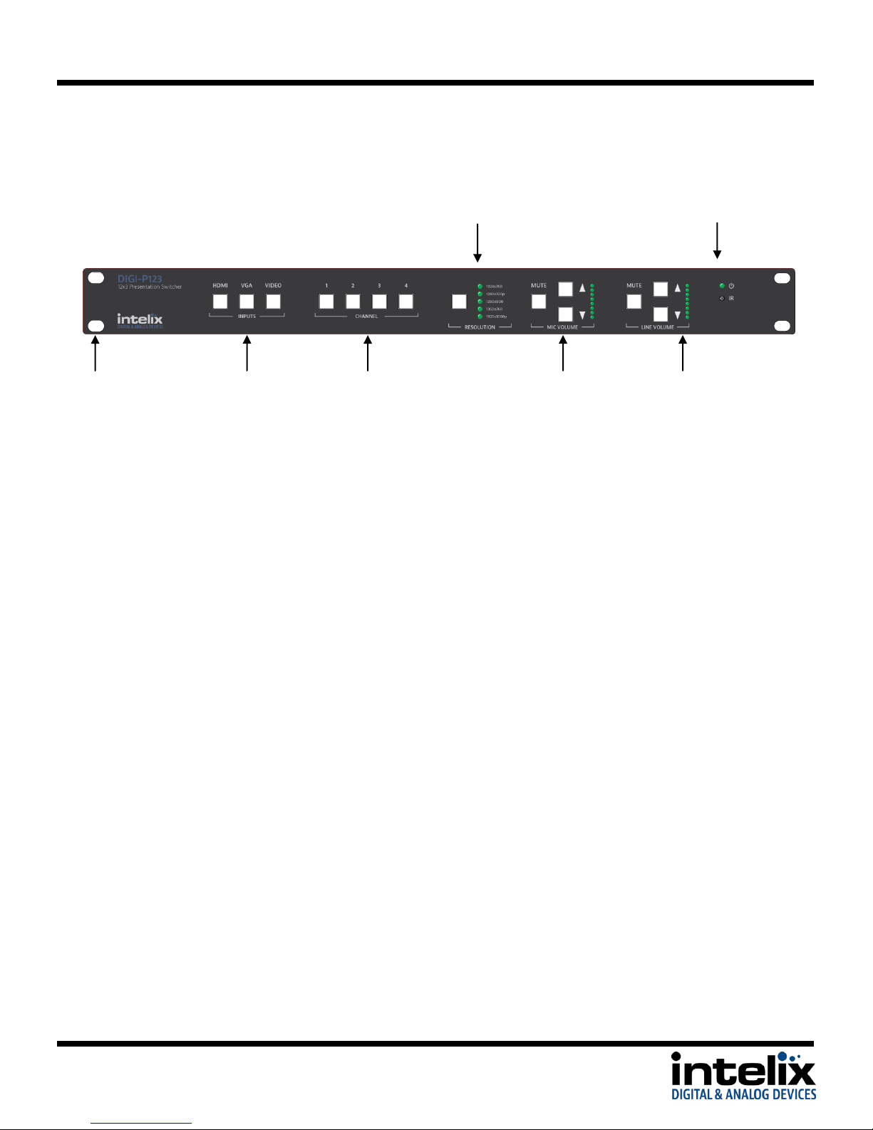
Input Channel
Selector Buttons
Input Type
Selector Buttons
Integrated
Rack Ears
Power LED/ IR
Receiver
Resolution Selector
Button and
Indicator
Mic Volume and
Mute Button /
Indicators
Line Volume and
Mute Button /
Indicators
Front Panel
Resolution Selector Button and Indicator – Sets the resolution for the output. All video input signals will be scaled to this
resolution.
Power LED/IR Receiver – Power LED will indicate whether the unit is on. Point IR remote at IR receiver for remote control
operation. If using a 3rd party IR control, place IR emitter over this window.
Integrated Rack Ears – 19”standardearsformountinginequipmentrack
Input Type Selector Buttons – Selects one of three input types to be displayed
Input Channel Selector Buttons – Selects one of four input channels (contingent upon input type selected). Press the Input
Type, then Input Channel to cause the unit to switch inputs.
Mic Volume and Mute Button / Indicators – Changes the level of the audio input connected to the mic/line input. This audio
inputwillmixwiththe“LineAudio”. Resulting mixed audio will be output on HDMI, line level output (VGA), and speaker level
output, as well as the HDBaseT output (DIGI-P123).
Line Volume and Mute Button / Indicators – Changes the level of the audio associated with the selected video input. This
audio input willmixwiththe“Mic Audio”. Resulting mixed audio will be output on HDMI, line level output (VGA), and speaker
level output, as well as the HDBaseT output (DIGI-P123).
Explanation of use for the front panel control is located in the section Front Panel Operation (page 9).
7
Page 8
DIGI-P122 / DIGI-P123 Installation Guide
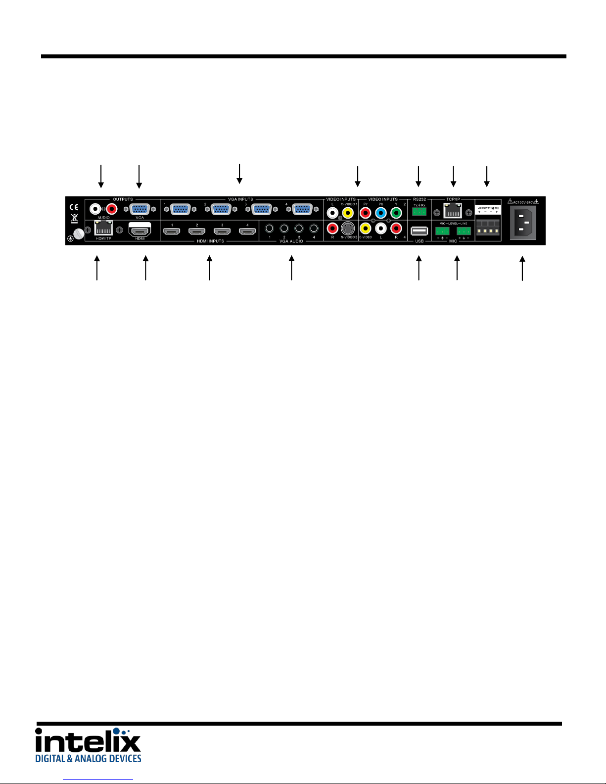
Line Level
Output
110-240 VAC
Input
VGA
Output
VGA
Inputs
Video
Inputs
RS232
Port
TCP/IP
Port
Speaker
Outputs
HDBaseT
Output (DIGI-
P123 only)
HDMI
Output
HDMI
Inputs
USB
Port
VGA Audio
Inputs
Microphone
Audio Input
Rear Panel
Line Level Output – Always-on stereo line level output (mix of Mic and selected Source audio)
VGA Output – Scaled VGA output. If source is encrypted HDMI, no video will be output from this port.
VGA Inputs – VGA input for PC signals, combined with associated VGA audio input
Video Inputs – Analog AV inputs and associated audio inputs
C-Video 1 – Composite video and audio input. Audio is shared with S-Video 3.
YPbPr 2 – Component video and audio input. Audio is shared with C-Video 4.
S-Video 3 – S-Video and audio input. Audio is shared with C-Video 1.
C-Video 4 – Composite video and audio input. Audio is shared with YPbPr 2.
RS232 Port – Control of the device can be achieved by connecting to this with a PC Com Port or 3rd party control system.
TCP/IP Port – Control of the device can be achieved by connecting to this with a Web Browser or 3rd party control system.
Speaker Outputs – Stereo output for 4/8Ωspeakers.10w/ch@8Ωor20w/ch@4Ω
HDBaseT Output – Extender output compatible with HDBaseT receivers. Scaled video outputs with Mix audio are transmitted.
This option is only available on the DIGI-P123.
HDMI Output – HDMI output. Scaled video output with mixed audio is transmitted.
HDMI Inputs – HDMI AV input
VGA Audio Inputs – Stereo audio inputs associated with VGA Inputs
USB Port – Used for firmware updating
Microphone audio input – Microphone or Line level input intended for use for speech reinforcement. Audio is mixed with
source audio and the resulting mix is transmitted on the HDMI, VGA, speaker, and HDBaseT outputs.
110-240VAC Input – AC Power Inlet
8
Page 9
DIGI-P122 / DIGI-P123 Installation Guide
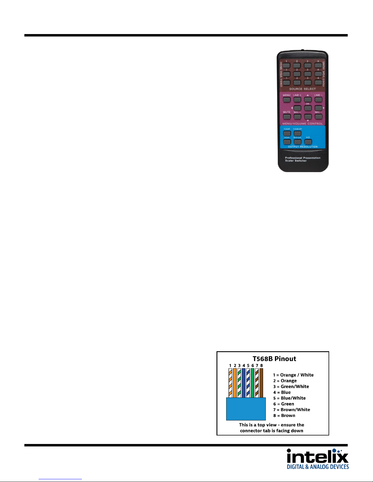
IR Remote
The included IR remote performs all of the functions available on the front
panel of the DIGI-P122/P123, and also allows acces to the setup menu.
Installation Instructions
Shelf Mounting Instructions
Attach the supplied rubber feet to the bottom of the unit.
Rack Mounting Instructions
The DIGI-P122/123 requires one rack unit (1 RU) of space. At least 2 inches of free air space is
required on both sides of the DIGI-P122/123 for proper side ventilation. Avoid mounting the
unit near a power amplifier or any other source of significant heat. It is recommended that you
leave an empty rack space above and below the DIGI-P122/123 for additional cooling.
Twisted Pair Output (DIGI-P123)
The DIGI-P123 includes an HDBaseT Lite extender
output. When used in conjunction with compatible
HDBaseT receivers (see Tech Specs), the scaled signal
may be transmitted up to 70m (230’) away.
Additionally, the user may connect via RS232 to the
HDBaseT receiver, and control the DIGI-P123.
Connection should be made using Cat6 unshielded or
shielded cable. Please terminate both ends using
EIA/TIA-568B crimp pattern, as shown in this diagram.
9
Page 10

DIGI-P122 / DIGI-P123 Installation Guide
Front Panel and IR Remote Operation
Basic Switching
To select an input from the front panel:
1. Press the Input Type button for the input you wish to select (HDMI, VGA, VIDEO)
2. Press the Input Channel button for input you wish to select (1,2,3,4)
To select an input from the IR remote:
1. Point the IR remote at the IR window on the front panel of the DIGI-P122/123
2. Press the Source Select button on the remote that corresponds to the input you wish to
select. There is a button for each input, regardless of type (HDMI, VGA, VIDEO)
Output Resolution
To change the output resolution from the front panel:
1. Press the Output Resolution button to cycle through output resolutions. The selected
resolution will be indicated by the LEDs to the right of the button.
2. Once you have selected the output resolution, it will take 3-5 seconds for the scaler to
perform the function. During this time you may see the picture flash, this is normal.
To change the output resolution from IR remote:
1. Point the IR remote at the IR window on the front panel of the DIGI-P122/123.
2. Press the Output Resolution button on the remote that corresponds to the resolution
you desire. There is a button for each output resolution.
3. Once you have selected the output resolution, it will take 3-5 seconds for the scaler to
perform the function. During this time you may see the picture flash, this is normal.
Volume and Mute
To change the volume of the MIC or LINE audio from the front panel:
1. Press the arrow up or down to raise or lower the volume, respectively. To make a large
change, you can press and hold the button until it reaches an appropriate level.
CAUTION: Increasing volume level too much can cause distortion or feedback, damage
speakers, and/or cause hearing loss.
To change the mute status of the MIC or LINE audio from the front panel:
1. Press the MUTE button that corresponds to the MIC or LINE audio you wish to mute.
10
Page 11

DIGI-P122 / DIGI-P123 Installation Guide
2. To cancel the mute, you can press the MUTE button again, or press the arrow UP or
DOWN buttons.
To change the volume of the MIC or LINE audio from the IR remote:
1. Point the IR remote at the IR window on the front panel of the DIGI-P122/123.
2. Press the + or - buttons to raise or lower the volume, respectively. To make a large
change, you can press and hold the button until it reaches an appropriate level.
CAUTION: Increasing volume level too much can cause distortion or feedback, damage
speakers, and/or cause hearing loss.
To change the mute status of the MIC and LINE audio from the IR remote:
1. Press the MUTE button – this will mute both the MIC and LINE audio.
2. To cancel the mute, you can press the MUTE button again, or press the + or – buttons for
MIC or LINE (only the MIC or LINE will unmute this way, depending on which buttons you
press).
See Page 8 for the button layout of the IR remote.
11
Page 12

DIGI-P122 / DIGI-P123 Installation Guide
EDID Management
HDMI
An essential part of operation is the EDID table, which is transmitted to the source via HDMI
cable from any HDMI input on the switcher. The DIGI-P122/123 units feature a dynamic EDID
mode for the HDMI inputs only. The preferred native timing of the EDID will match the output
resolution that the DIGI-P122/123 is set to. For example – if the output resolution of the unit is
set to 1024x768, then the switcher will request the source to output 1024x768. The benefit of
this method is that the video output by the source will not need to undergo a great deal of
processing (scaling), which will result in a cleaner image with less scaling artifacts.
VGA
Similar to the HDMI inputs, the VGA inputs must transmit a table of acceptable resolutions to
the attached source. The VGA inputs of the DIGI-P122/123 are static, and will always request a
resolution of 1360x768 from the source.
HDCP Management
HDMI Inputs
The HDMI inputs are HDCP compliant, which will allow you to use encrypted content like a BluRay player. The DIGI-P122/123 will only consume one HDCP “key”, regardless of what is
connected on the outputs.
HDMI and HDBaseT Outputs
The HDMI outputs will follow the status of the input. If the source is encrypted, the output will
be encrypted; if the source is un-encrypted, the output of the DIGI-P122/123 will be
unencrypted.
VGA Output
The VGA video output will be turned off when a HDCP encrypted input is selected (HDMI only).
A black screen will replace the video input. This operation is normal, as it is necessary to
comply with HDCP regulations. Stereo audio from the PC
For more information about HDCP, please visit www.digital-cp.com
12
Page 13
DIGI-P122 / DIGI-P123 Installation Guide
TCP/IP Setup and Control
IP Address Setup via Web Browser
Configuring the TCP/IP port is done via a web browser interface. A crossover cable is required
for the initial setup. The default IP address is printed on a sticker on the side of the DIGIP122/123.
1. Configure the computer to use the same network prefix as the IP address assigned to
the DIGI-P122/123. For example, the IP address of the DIGI-P122/123 is 192.168.0.178.
Set the computer to use a static IP address within the same network range, such as
192.168.0.42.
2. Connect the crossover cable to the computer and to the TCP/IP port on the DIGI-
P122/123.
3. Open up Internet Explorer (Firefox, Chrome, and Safari crop the configuration options).
4. Enter the IP address printed on the sticker into the browser URL bar, which will take you
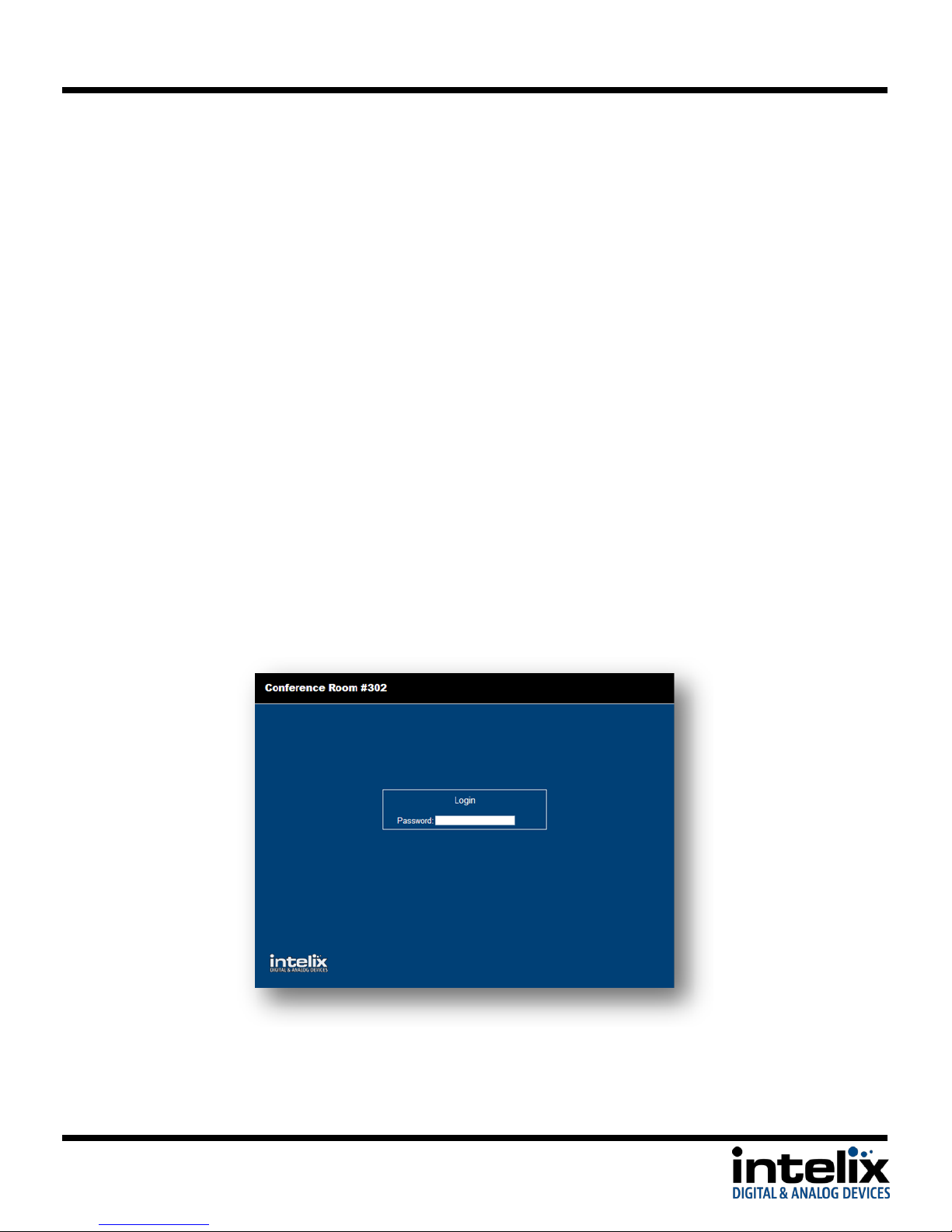
to the Login screen.
5. TheDefaultpasswordis“888888”.
13
Page 14
DIGI-P122 / DIGI-P123 Installation Guide
a
b
c
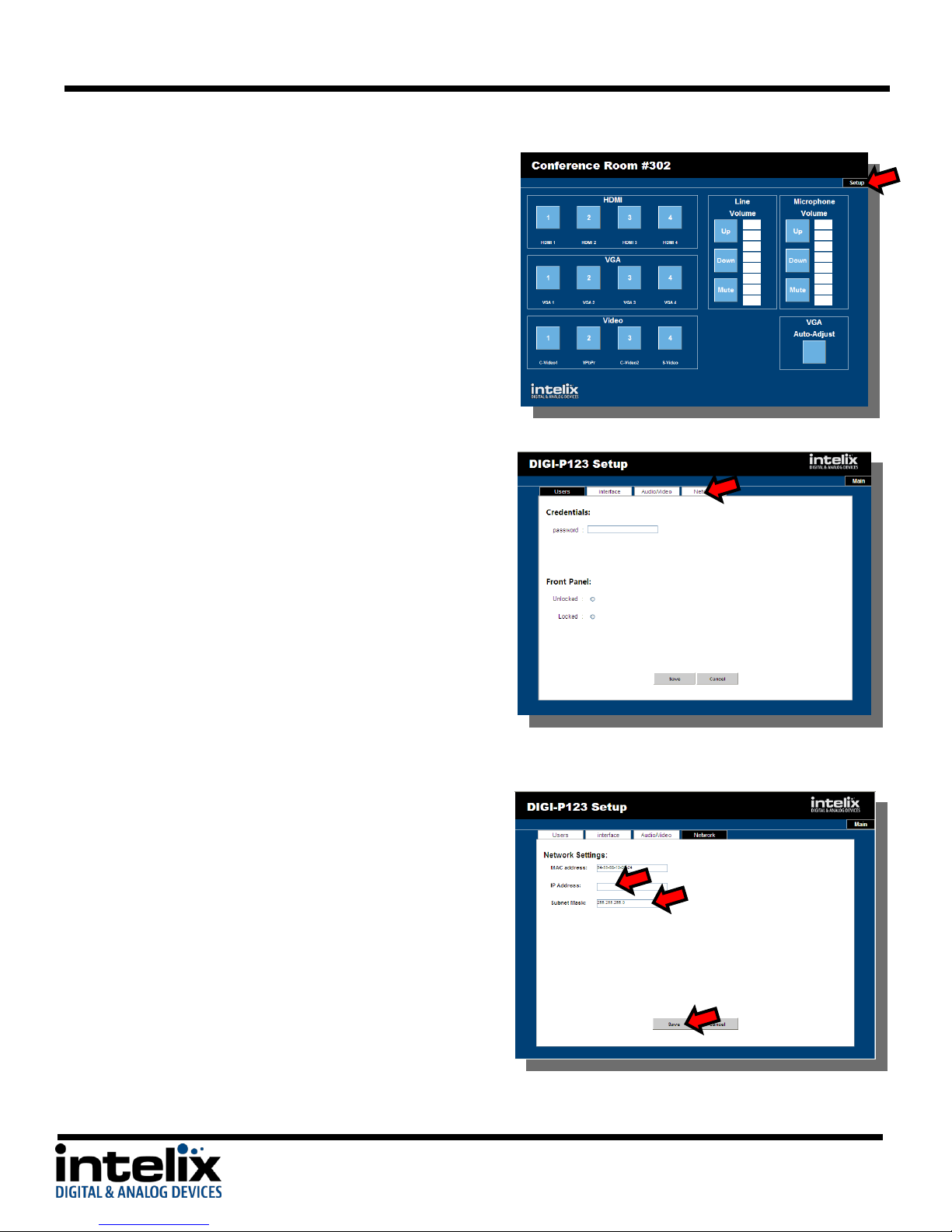
6. Click the “Setup” button to enter the
configuration menu.
7. Selectthe“Network”tab
8. Enter the new settings provided by your
network administrator:
a. Enter the new IP address.
b. Enter the new Subnet Mask.
c. Pressthe“Save”button.
9. Enter the new IP address into your browser
URL bar to re-establish communications.
14
Page 15
DIGI-P122 / DIGI-P123 Installation Guide
Access the Web Browser with Defined IP Address
1. Remove the crossover cable between the computer and the DIGI-P122/123.
2. Restore the computer to the previous network settings.
3. Connect the computer and the DIGI-P122/123 to the network.
4. Using Internet Explorer, enter the IP address for the matrix to access the browser
interface.
Additional Options in Web Browser
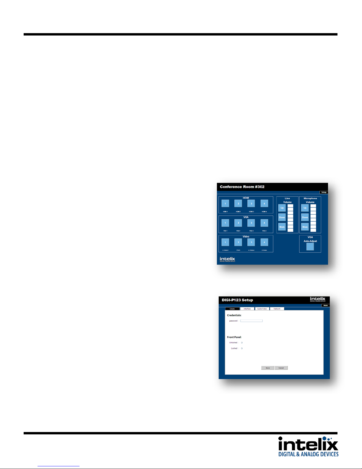
1. Operation Page:
a. AV switching: You may select an input
channel by pressing the buttons on
the left side of the page.
b. Volume and Mute Control: You may
change the volume and mute status
of the MIC and LINE audio. The level
is indicated in the indicator bars.
c. VGA Auto-Adjust – When a VGA input
is selected, you can press this button,
and the scaler will re-adjust the
image.
2. Users tab:
a. Credentials: You can change the
default password for the web browser
interface (GUI). Enter the new
passwordandpress“Save”
b. Front Panel: You can set the front
panel of the DIGI-P122/123 to be
locked or unlocked by pressing the
associated radio button.
15
Page 16
DIGI-P122 / DIGI-P123 Installation Guide
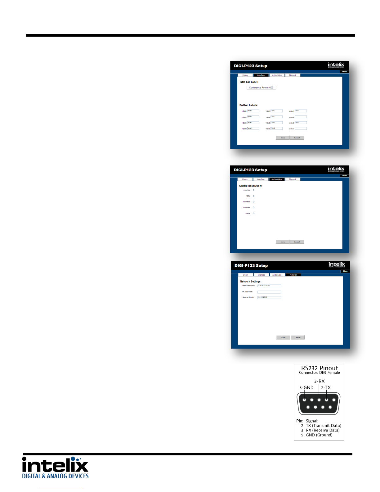
3. Interface Tab
a. Title Bar Label: You may enter a name
in this field. It will appear in the black
top bar on the Login and Operation
pages.
b. Button Labels: Enter names in these
fields to identify the type of input that
is connected to the DIGI-P122/123.
Examples might be “Bluray”,
“Wallplate1”,or“AppleTV”.
4. Audio/Video Tab:
a. Output Resolution: You may change
the output resolution from this screen
by clicking on one of the radio buttons.
This performs the same action as the
front panel or remote commands.
5. Network Tab:
a. Network Settings: The unit’s MAC
address, IP address, and current
subnet mask are displayed in these
fields. Please see TCP/IP Setup and
Control on page 12 for more
information. The MAC address field is
not editable.
RS232 Connection
The RS232 control port requires a standard straight-through serial cable for
operation. This diagram shows the connections for the DIGI-P122/123 as you
look at the connector. The default settings for the RS232 port are:
- 9600 baud
- 8 Data Bits
- 1 Stop Bit
- Parity = none
16
Page 17
DIGI-P122 / DIGI-P123 Installation Guide
Description
Command
Response
HDMI 1 input select
0701%
Source: HDMI 1<CR><LF>
HDMI 2 input select
0702%
Source: HDMI 2<CR><LF>
HDMI 3 input select
0703%
Source: HDMI 3<CR><LF>
HDMI 4 input select
0704%
Source: HDMI 4<CR><LF>
VGA 1 input select
0705%
Source: VGA 1<CR><LF>
VGA 2 input select
0706%
Source: VGA 2<CR><LF>
VGA 3 input select
0707%
Source: VGA 3<CR><LF>
VGA 4 input select
0708%
Source: VGA 4<CR><LF>
Composite video (AV1) input select
0709%
Source: CVIDEO 1<CR><LF>
YPbPr input select
0710%
Source: YPbPr<CR><LF>
S-Video input select
0711%
Source: SVIDEO<CR><LF>
Composite video (AV2) input select
0712%
Source: CVIDEO 2<CR><LF>
Get the currently selected input source
0631%
Displays one of the above Source:
responses
Description
Command
Response
Set the resolution to 1360x768 (HD)
0618%
Resolution: HD
1360X768<CR><LF>
Set the resolution to 1024x768 (XGA)
0626%
Resolution: XGA
1024X768<CR><LF>
Set the resolution to 1280x720 (720p)
0627%
Resolution: 720P
1280X720<CR><LF>
Set the resolution to 1280x800 (WXGA)
0628%
Resolution: WXGA
1280X800<CR><LF>
Set the resolution to 1920x1080 (1080p)
0629%
Resolution: 1080P
1920X1080<CR><LF>
Get the currently selected output resolution
0632%
Displays one of the above
Resolution: responses
Aspect Mode – Output Native On
0661%
Native On<CR><LF>
Aspect Mode – Output Native Off
0660%
Native Off<CR><LF>
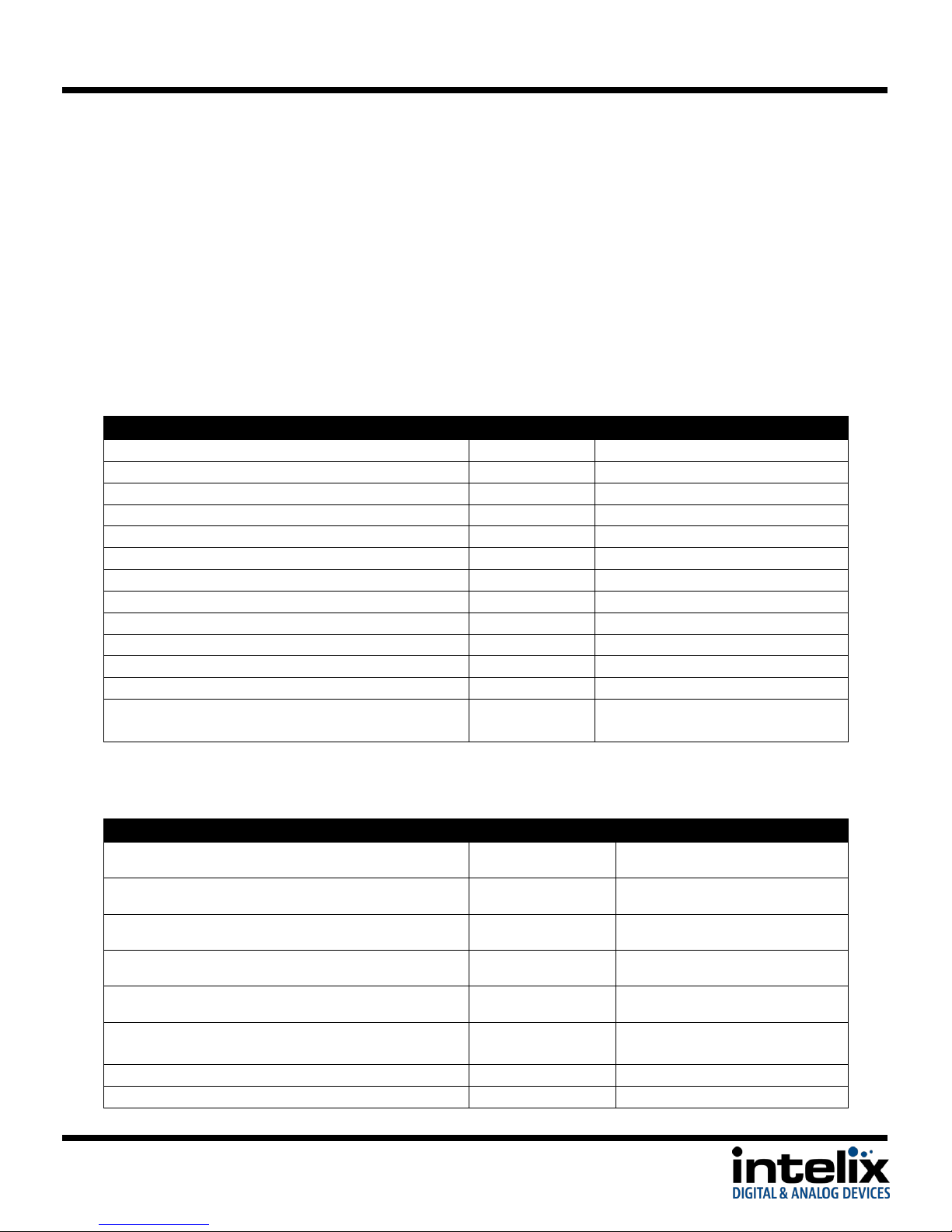
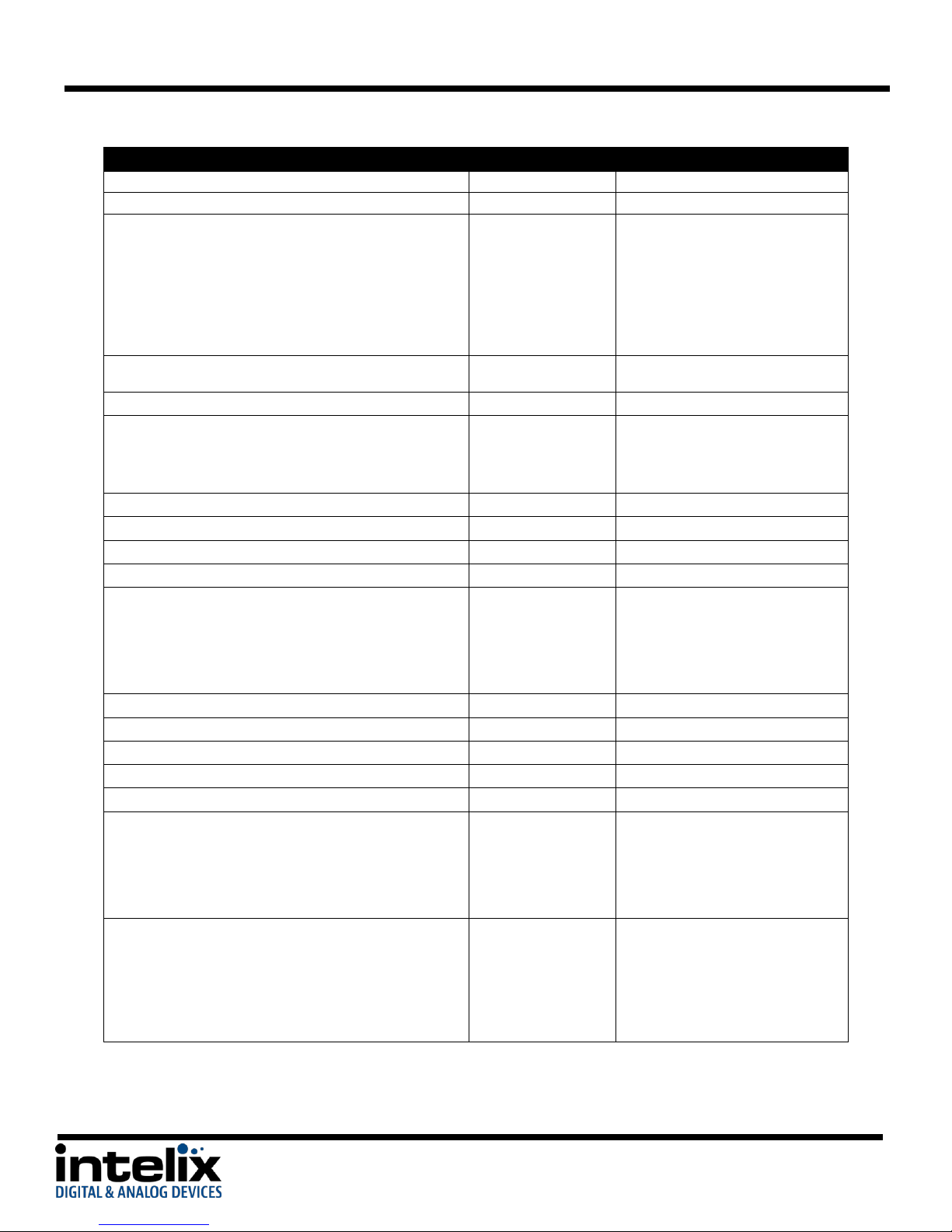
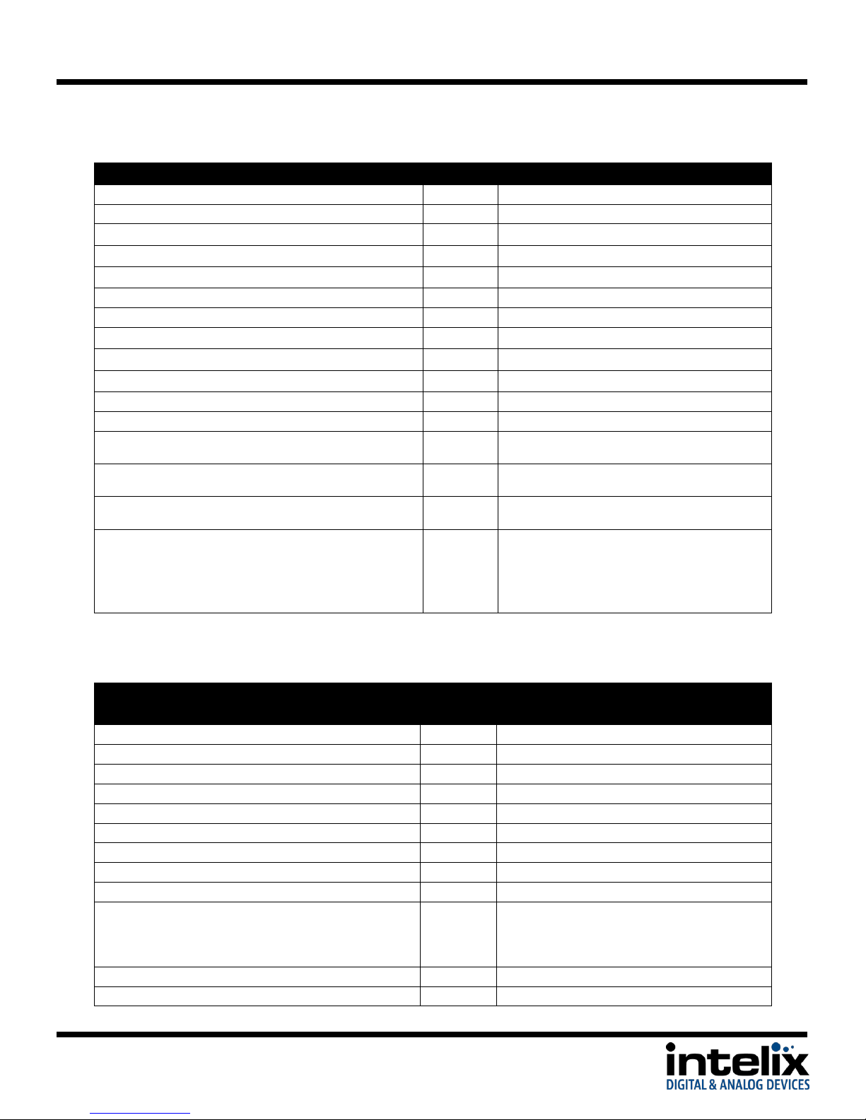
RS232 and TCP/IP Commands
RS232 Settings: 9600 baud, 8 Data bits, 1 Stop bit, Parity = None
TCP/IP Settings: User defined IP address, port 4001
<CR> = Carriage return (Hex 0D)
<LF> = Line Feed (Hex 0A)
Switching Commands
Video Commands
17
Page 18
DIGI-P122 / DIGI-P123 Installation Guide
Description
Command
Response
Aspect Mode – Output 16:9
0662%
Ratio: 16:9<CR><LF>
Aspect Mode – Output 4:3
0663%
Ratio: 4:3<CR><LF>
Aspect Mode – Set zoom mode (cycle)
0608%
Aspect Ratio:
[xxxxxxx]<CR><LF>
[xxxxxxx] can be:
4:3
Full
Wide Screen
Subtitle
Freeze Image – Enable
0655%
Freeze: Enable<CR><LF>
Freeze Image – Disable
0656%
Freeze: Disable<CR><LF>
VGA Auto-adjust
0606%
Non-VGA:
Not Support<CR><LF>
VGA:
VGA Adjustment<CR><LF>
Set brightness at [xx], [xx] ranges at 00~99
02[xx]%
Brightness: [xx]
Set contrast at [xx], [xx] ranges at 00~99
03[xx]%
Contrast: [xx]
Set saturation at [xx], [xx] ranges at 00~99
04[xx]%
Saturation: [xx]
Set sharpness at [xx], [xx] ranges at 00~07
05[xx]%
Sharpness: [xx]
Set color temperature
0607%
Color Temp: [xx]
[xx] can be:
Normal
Warm
Cool
Set picture mode (cycle)
0614%
Get the brightness, [xx] ranges at 00~99
0636%
Brightness: [xx]
Get the contract, [xx] ranges at 00~99
0637%
Contrast: [xx]
Get the saturation, [xx] ranges at 00~99
0638%
Saturation: [xx]
Get the sharpness, [xx] ranges at 00~07
0639%
Sharpness: [xx]
Get color temperature
0640%
Color Temp: [xx]
[xx] can be:
Normal
Warm
Cool
Get picture mode
0633%
Picture Mode : [xx]
[xx] can be:
User
Standard
Bright
Soft
18
Page 19
DIGI-P122 / DIGI-P123 Installation Guide
Description
Command
Response
Mute LINE
0600%
LINE Mute On<CR><LF>
Unmute LINE
0601%
LINE Mute Off<CR><LF>
LINE volume up, [xx] ranges at 00~100
0602%
LINE Volume: [xx]<CR><LF>
LINE volume down, [xx] ranges at 00~100
0603%
LINE Volume: [xx]<CR><LF>
Set LINE Volume to [xx], [xx] ranges at 00~100
01[xx]%
LINE Volume: [xx]<CR><LF>
Mute MIC
0722%
MIC Mute On<CR><LF>
Unmute MIC
0723%
MIC Mute Off<CR><LF>
MIC volume up, [yy] ranges at 00~60
0724%
MIC Volume: [yy]<CR><LF>
MIC volume down, [yy] ranges at 00~60
0725%
MIC Volume: [yy]<CR><LF>
Set MIC Volume to [yy], [yy] ranges at 00~60
08[yy]%
MIC Volume: [yy]<CR><LF>
Mute ALL
0720%
Mute On<CR><LF>
Unmute ALL
0721%
Mute Off<CR><LF>
Get the current volume level, ranges at 00~100
0630%
LINE Volume: [xx] <CR><LF>
MIC Volume: [yy]<CR><LF>
Digital audio (HDMI) output enable
0648%
Digital Sound Output:
Enable<CR><LF>
Digital audio (HDMI) output disable
0649%
Digital Sound Output:
Disable<CR><LF>
Get digital audio output status
0652%
Digital Sound Output:
Enable<CR><LF>
OR
Digital Sound Output:
Disable<CR><LF>
Description
Comma
nd
Response
Lock the front panel
0604%
Panel Locked<CR><LF>
Unlock the front panel
0605%
Panel UnLocked<CR><LF>
Reset to factory defaults
0617%
Factory reset<CR><LF>
System Menu
0616%
MENU<CR><LF>
Enter/OK
0609%
OK<CR><LF>
Menu Left
0610%
Left<CR><LF>
Menu Right
0611%
Right<CR><LF>
Menu Up
0612%
Up<CR><LF>
Menu Down
0613%
Down<CR><LF>
Get firmware version (Video Processor)
0699%
DIGI-P12X V[xxxxxxx]<CR><LF>
[xxxxxxx] can be:
1.2.0.19
Factory Reset
0617%
Factory reset<CR><LF>
***Update Firmware***
0698%
SEE INSTRUCTIONS on Page 21
Audio Commands
Menu/System Commands
19
Page 20
DIGI-P122 / DIGI-P123 Installation Guide
Description
Command
Response
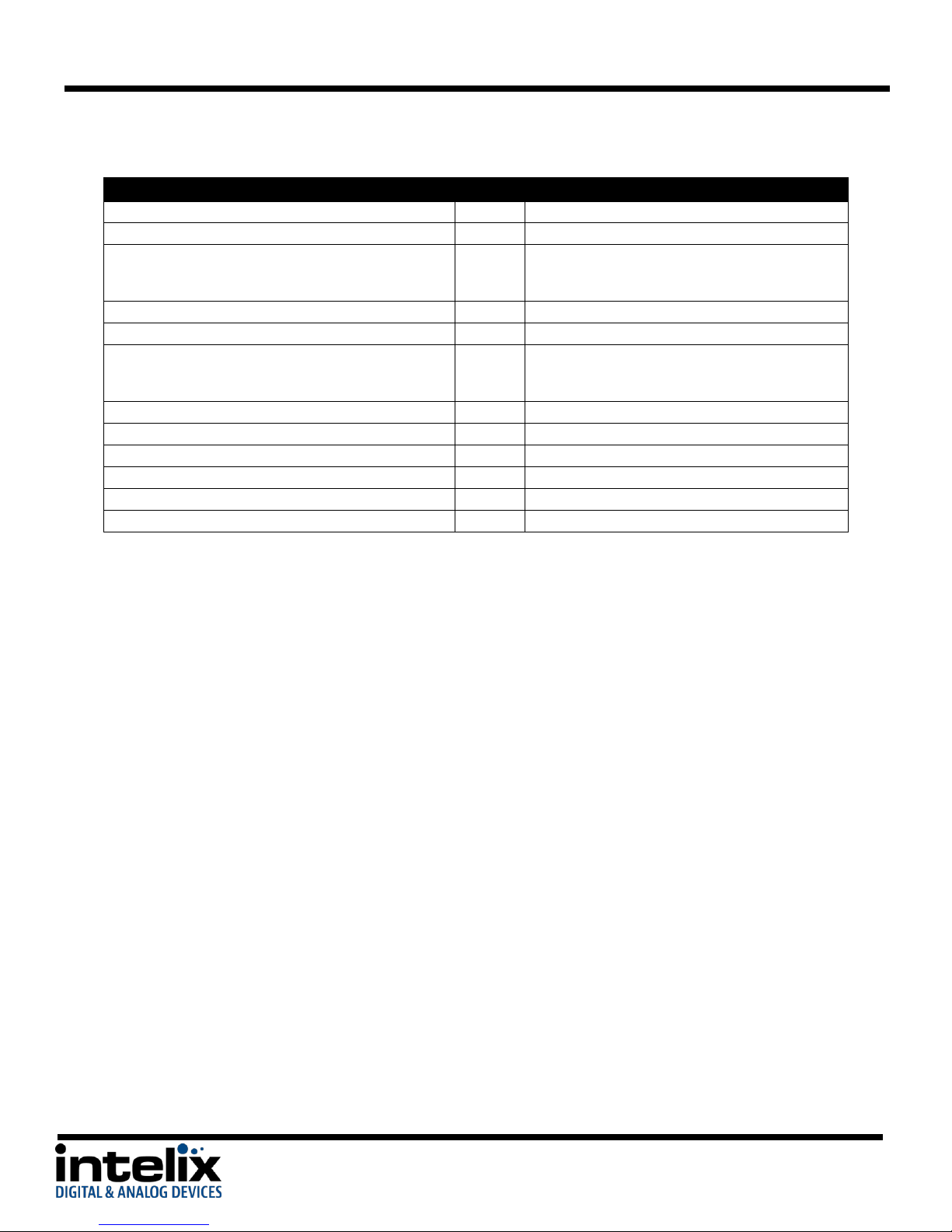
Volume Bar display enable
0646%
Volume Bar: Display<CR><LF>
Volume Bar display disable
0647%
Volume Bar: No Display<CR><LF>
Get Volume Bar display status
0651%
Volume Bar: Display<CR><LF>
OR
Volume Bar: No Display<CR><LF>
Display on-screen source - Enable
0644%
OSD Source: Display<CR><LF>
Display on-screen source - Disable
0645%
OSD Source: No Display<CR><LF>
On-screen source display status
0650%
OSD Source: Display<CR><LF>
OR
OSD Source: No Display<CR><LF>
Enable on-screen icon for Line Mute/Unmute
0761%
ICON LINE Mute: ENABLED<CR><LF>
Disable on-screen icon for Line Mute/Unmute
0762%
ICON LINE Mute: DISABLED<CR><LF>
Enable on-screen icon of Mic Mute/Unmute
0763%
ICON MIC Mute: ENABLED<CR><LF>
Disable on-screen icon for Mic Mute/Unmute
0764%
ICON MIC Mute: DISABLED<CR><LF>
Enable on-screen icon for Freeze Output
0765%
ICON Freeze: ENABLED<CR><LF>
Disable on-screen icon for Freeze Output
0766%
ICON Freeze: DISABLED<CR><LF>
OSD (On Screen Display) Commands
20
Page 21

DIGI-P122 / DIGI-P123 Installation Guide
Firmware Update
The DIGI-P122/P123 supports firmware updating in the field by USB thumb drive. The
operation is as follows:
1. Connect the DIGI-P122/123 output to a display with a HDMI or VGA cable.
2. Apply power to the DIGI-P122/123.
3. Copythefile“MT23ATV.bin”toaUSBflashdisk.(The“MT23ATV.bin”fileis
provided/authorized by Intelix engineering department)
4. Insert the USB thumb drive into the USB port on the DIGI-P122/123
5. Press the HDMI button on the front panel of the DIGI-P122/123 for 6 seconds OR send
the RS232 command 0698%
6. Pressthe“OK”buttonontheIRremoteOR send the RS232 command 0609% to confirm
the update procedure.
7. Wait for the update to finish (a progress bar will appear on the screen).
8. Power cycle the DIGI-P122/123 (unplug the power cable, wait three seconds, and plug it
back in)
9. Send the RS232 command 0617% to reset the unit to factory settings.
10. Power cycle the DIGI-P122/123 (unplug the power cable, wait three seconds, and plug it
back in)
Notice: The name of the firmware file must be MT23ATV.bin.
21
Page 22

DIGI-P122 / DIGI-P123 Installation Guide
Troubleshooting
Unit does not power on
Verify power outlet is active.
Verify continuity in power cable.
Unit does not respond to front panel buttons
Front panel is locked – send RS232 command 0605%
No video from VGA output
Check VGA cable.
HDMI source may be encrypted (Bluray player, etc.) This is normal, encrypted sources cannot
be converted to HD analog.
Switcher output may be an incompatible video format – change output resolution.
Audio distorted
Turn volume down.
If using a line level source, be sure that it is connected to the line level input of the MIC.
No microphone audio
Be sure the microphone is connected to the mic level input of the MIC.
Check the microphone – if it is a condenser (electrostatic), it may require phantom power. The
DIGI-P122/123 does not supply phantom power.
22
Page 23
DIGI-P122 / DIGI-P123 Installation Guide
Stereo input sounds strange (no vocals, etc.)
The line level connector of the MIC input is balanced. If you are trying to input a stereo source,
both the Left (+) and Right (+) must be connected to the (+) terminal on the DIGI-P122/123,
while the ground should be connected to the (-) and the ground. Better still – use a summing
adapter (RDL TX-J2 comes to mind).
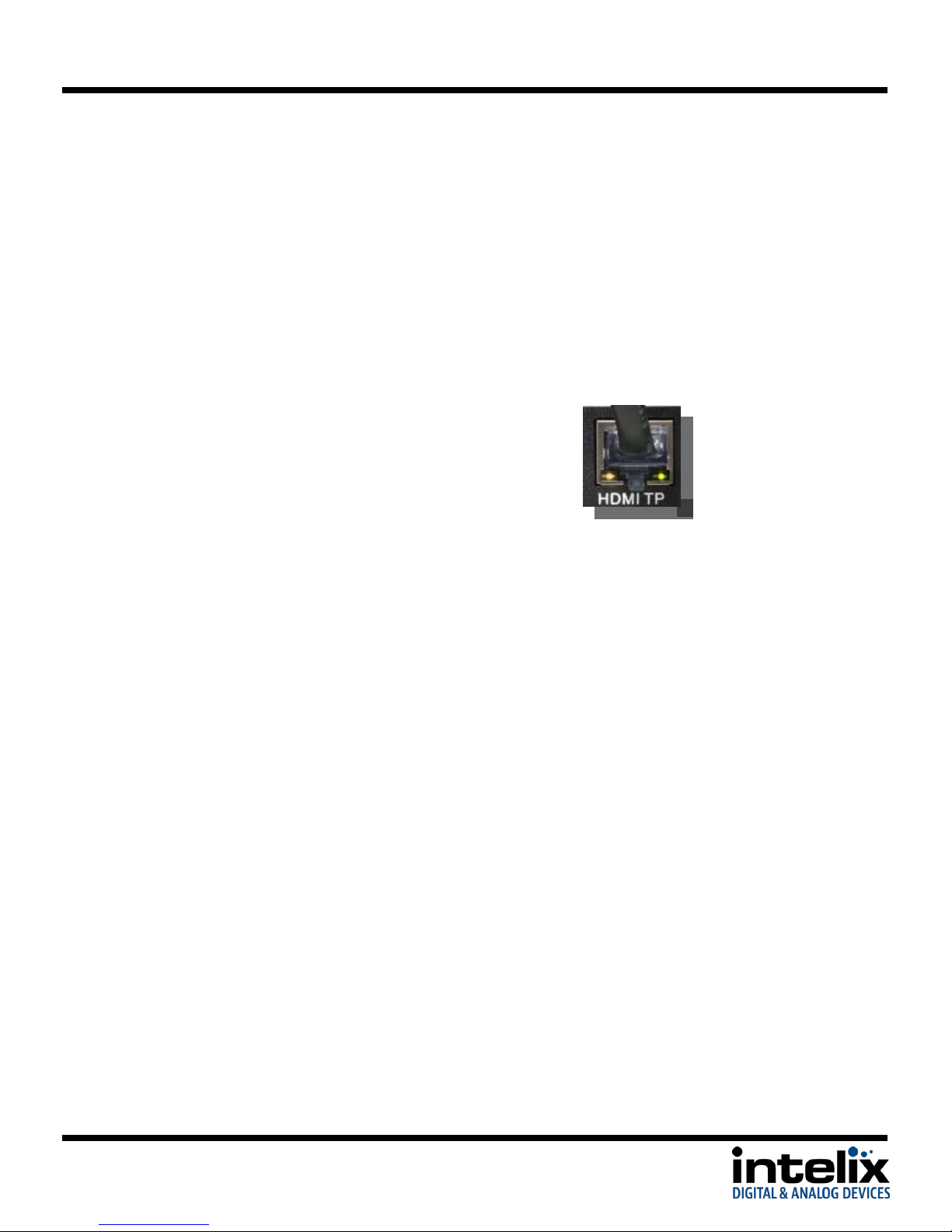
No video from HDBaseT output
Verify the green link LED on the HDBaseT card is lit solid.
23
Page 24
DIGI-P122 / DIGI-P123 Installation Guide
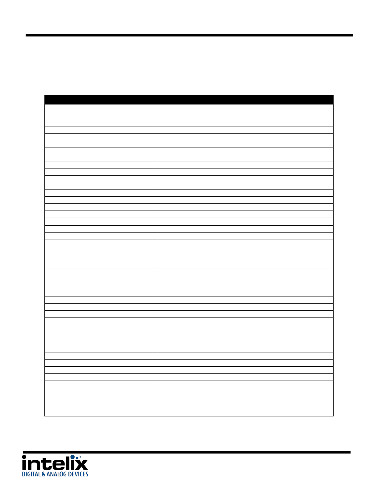
Technical Specifications
Input Connections
HDMI Inputs
Four (4) HDMI type A
VGA Inputs
Four (4) HD15-F, Four (4) 3.5mm TRS-F
Composite Video 1
One (1) RCA-F (video), Two (2) RCA-F (stereo audio shared with S-Video 3)
YPbPr 2 (Component Video)
Three (3) RCA-F (video), Two (2) RCA-F (stereo audio shared with
Composite Video 4)
S-Video 3
One (1) 4PMD-F (video), Two (2) RCA-F (stereo audio shared with
Composite Video 1)
Composite Video 4
One (1) RCA-F (video), Two (2) RCA-F (stereo audio shared with YPbPr 2)
Microphone Input (Line Level)
One (1) 3-Pole/3.5mm Euroblock (audio summed with Mic Level input)
Microphone Input (Mic Level)
One (1) 3-Pole/3.5mm Euroblock Connector (audio summed with Line
Level input)
Control (Front Panel)
Push Button, IR
Control (Rear Panel)
RS232 via 3-Pole/3.5mm Euroblock, TCP/IP via 8P8C
Power Input
One (1) IEC-C14 Power Inlet
Firmware Upgrade
USB Type A Female
Output Connections
HDMI Output
One (1) HDMI type A
VGA Output
One (1) HD15-F
Stereo Analog Audio
Two (2) RCA (stereo audio)
Speaker Output
One (1) 4-Pole/5.08mm Euroblock
Video Performance
HDMI Input Bandwidth
4.95Gbps (1.65Gbps per color)
HDMI Input Resolutions
640x480: 60/72/75/85 Hz, 800x600: 56/60/72/75/85 Hz, 1024x768:
60/70/75/85 Hz, 1280x768: 60 Hz, 1280x1024: 60/75Hz, 1360x768: 60 Hz,
720x480i/p (4:3 and 16:9), 720x576i/p (4:3 and 16:9), 1280x720p: 50/60
Hz, 1920x1080i: 25/30 Hz, 1920x1080p: 50/60 Hz
HDMI Input Compatibility
HDMI 1.3, DVI-D
HDMI Input Compliance
HDCP Compliant**
VGA Input Bandwidth
375MHz
VGA Input Resolutions
640x480: 60/72 Hz, 720x400: 60 Hz, 800×600: 60/72/75 Hz, 1024×768:
60/70/75 Hz, 1280x720: 60 Hz, 1280×768: 60Hz, 1280x960: 60 Hz,
1280×1024: 60/75Hz, 1360×768: 60Hz, 1440x900: 60 Hz, 1600x1200: 60
Hz, 1680x1050: 60 Hz, 1920×1080: 60 Hz
VGA Input Compatibility
RGBHV, RGBs, RGsB, RsGsBs
Composite, S-Video Input Bandwidth
150MHz
Composite, S-Video Input Compatibility
NTSC 3.58, NTSC 4,42, PAL, SECAM
Component Video Input Bandwidth
170MHz
Component Video Input Resolutions
480i, 480p, 576i, 576p, 720p, 1080i, 1080p
Output Resolutions
1920x1080, 1360x768, 1280x720, 1280x800, 1024x768
Video Impedance
75ohm
Maximum Pixel Clock
145MHz
Video Gain
0dB
Signal Level
0.5V~2.0Vp-p
Technical Specifications
DIGI-P122
24
Page 25
DIGI-P122 / DIGI-P123 Installation Guide
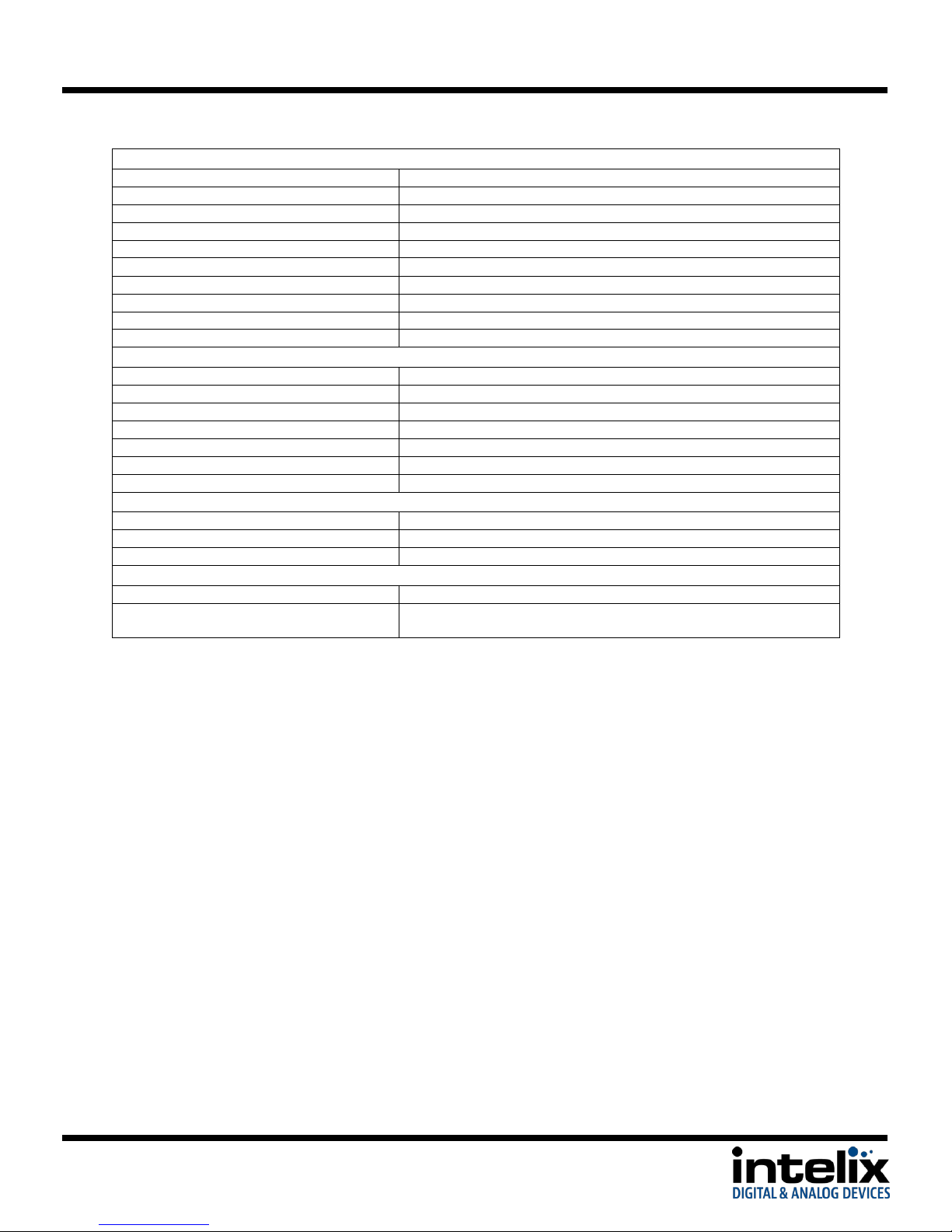
Audio Performance
RCA/3.5mm Input Signal Level
-10dBv Nominal
RCA/3.5mm Input Impedance
>10k ohm
MIC Input Signal Level
-48dB Nominal (Mic input), +4dBu Nominal (Line Input)
MIC Input Impedance
600 ohm (Mic input), >10k ohm (Line input)
ADC Format
24bit, 48kHz, 2ch LPCM
Line Level Output Impedance
50 ohm
Speaker Output
2x10W @ 8ohm / 2x20W @ 4ohm
Frequency Response
20Hz-20kHz
Stereo Channel Separation
>80dB @ 1kHz
Common Mode Rejection
>90dB @ 20Hz-20kHz
Chassis and Environmental
Enclosure
Painted Aluminum
Dimensions
483mm x 235mm x 44mm (19 in x 9.25 in x 1.73 in) – 1RU
Shipping Weight
3.74 kg (8.25 lbs.)
Operating Temperature
0° to +48° C (+32° to +120° F)
Operating Humidity
10% to 90%, Non-condensing
Storage Temperature
-20° to +70° C (+14° to +158° F)
Storage Humidity
10% to 85%, Non-condensing
Power and Regulatory
Maximum Power Consumption
65 watts
Power Supply
100vAC~240vAC, 50/60Hz
Regulatory
CE, RoHS
Other
Warranty
2 years
Included Accessories
IR Remote, Power Cable, Four (4) Rubber Feet, Serial Cable (DE9-F to
Euroblock), Operation Guide
**VGA Output will turn off when encrypted content is selected.
Distances and picture quality may be affected by cable grade, cable quality, source and destination equipment, RF and electri cal interference, and cable patches. Intelix
specifications are based on straight-through cabling with standard-grade Cat 5e unless noted otherwise.
25
Page 26
DIGI-P122 / DIGI-P123 Installation Guide
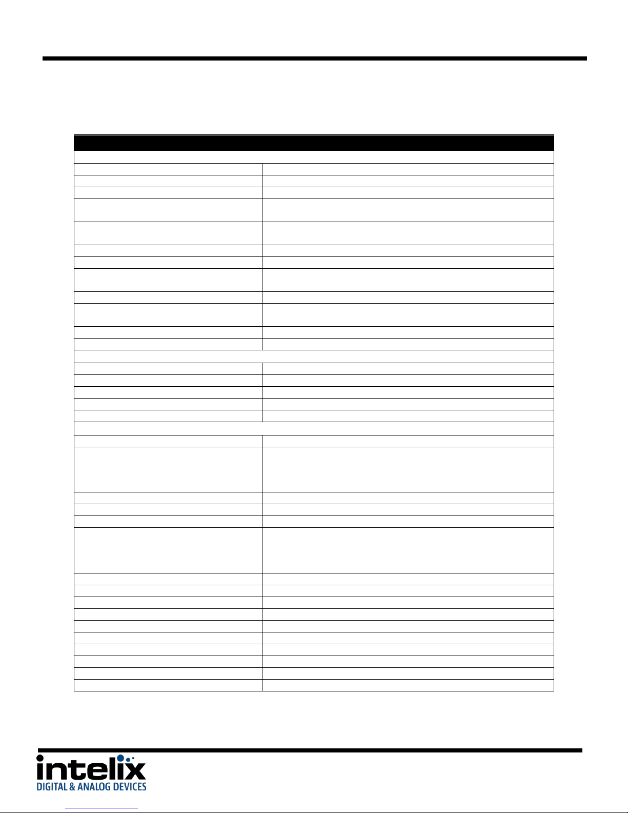
Technical Specifications
Input Connections
HDMI Inputs
Four (4) HDMI type A
VGA Inputs
Four (4) HD15-F, Four (4) 3.5mm TRS-F
Composite Video 1
One (1) RCA-F (video), Two (2) RCA-F (stereo audio shared with S-Video 3)
YPbPr 2 (Component Video)
Three (3) RCA-F (video), Two (2) RCA-F (stereo audio shared with
Composite Video 4)
S-Video 3
One (1) 4PMD-F (video), Two (2) RCA-F (stereo audio shared with
Composite Video 1)
Composite Video 4
One (1) RCA-F (video), Two (2) RCA-F (stereo audio shared with YPbPr 2)
Microphone Input (Line Level)
One (1) 3-Pole/3.5mm Euroblock (audio summed with Mic Level input)
Microphone Input (Mic Level)
One (1) 3-Pole/3.5mm Euroblock Connector (audio summed with Line
Level input)
Control (Front Panel)
Push Button, IR
Control (Rear Panel)
RS232 via 3-Pole/3.5mm Euroblock, TCP/IP via 8P8C, RS232 via HDBaseT
Output (8P8C-F)*
Power Input
One (1) IEC-C14 Power Inlet
Firmware Upgrade
USB Type A Female
Output Connections
HDMI Output
One (1) HDMI type A
VGA Output
One (1) HD15-F
Stereo Analog Audio
Two (2) RCA (stereo audio)
HDBaseT Output
One (1) 8P8C-F
Speaker Output
One (1) 4-Pole/5.08mm Euroblock
Video Performance
HDMI Input Bandwidth
4.95Gbps (1.65Gbps per color)
HDMI Input Resolutions
640x480: 60/72/75/85 Hz, 800x600: 56/60/72/75/85 Hz, 1024x768:
60/70/75/85 Hz, 1280x768: 60 Hz, 1280x1024: 60/75Hz, 1360x768: 60 Hz,
720x480i/p (4:3 and 16:9), 720x576i/p (4:3 and 16:9), 1280x720p: 50/60
Hz, 1920x1080i: 25/30 Hz, 1920x1080p: 50/60 Hz
HDMI Input Compatibility
HDMI 1.3, DVI-D
HDMI Input Compliance
HDCP Compliant**
VGA Input Bandwidth
375MHz
VGA Input Resolutions
640x480: 60/72 Hz, 720x400: 60 Hz, 800×600: 60/72/75 Hz, 1024×768:
60/70/75 Hz, 1280x720: 60 Hz, 1280×768: 60Hz, 1280x960: 60 Hz,
1280×1024: 60/75Hz, 1360×768: 60Hz, 1440x900: 60 Hz, 1600x1200: 60
Hz, 1680x1050: 60 Hz, 1920×1080: 60 Hz
VGA Input Compatibility
RGBHV, RGBs, RGsB, RsGsBs
Composite, S-Video Input Bandwidth
150MHz
Composite, S-Video Input Compatibility
NTSC 3.58, NTSC 4,42, PAL, SECAM
Component Video Input Bandwidth
170MHz
Component Video Input Resolutions
480i, 480p, 576i, 576p, 720p, 1080i, 1080p
Output Resolutions
1920x1080, 1360x768, 1280x720, 1280x800, 1024x768
Video Impedance
75ohm
Maximum Pixel Clock
145MHz
Video Gain
0dB
Signal Level
0.5V~2.0Vp-p
DIGI-P123
26
Page 27
DIGI-P122 / DIGI-P123 Installation Guide
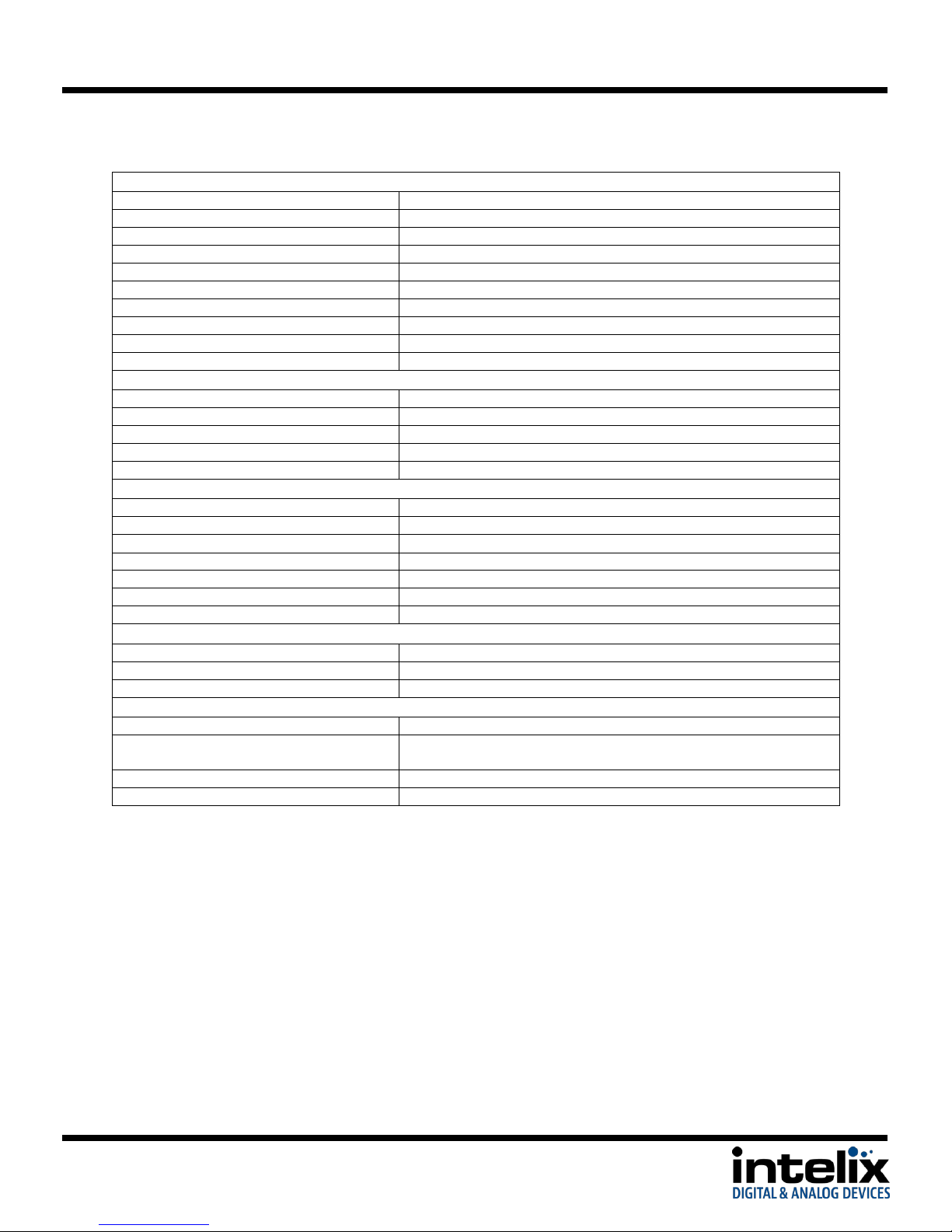
Audio Performance
RCA/3.5mm Input Signal Level
-10dBv Nominal
RCA/3.5mm Input Impedance
>10k ohm
MIC Input Signal Level
-48dB Nominal (Mic input), +4dBu Nominal (Line Input)
MIC Input Impedance
600 ohm (Mic input), >10k ohm (Line input)
ADC Format
24bit, 48kHz, 2ch LPCM
Line Level Output Impedance
50 ohm
Speaker Output
2x10W @ 8ohm / 2x20W @ 4ohm
Frequency Response
20Hz-20kHz
Stereo Channel Separation
>80dB @ 1kHz
Common Mode Rejection
>90dB @ 20Hz-20kHz
Extender Signal Characteristics
Maximum Distance per Linked Unit (Cat 5e)
70m(230’)
Cable Requirements
Category 5e, 6, or 6A with TIA/EIA-568B crimp pattern
Bandwidth
6.75 Gbps
Input DDC Signal
5.0 volts p-p (TTL)
Input Video Signal
0.5 to 1.0 volts p-p
Chassis and Environmental
Enclosure
Painted Aluminum
Dimensions
483mm x 235mm x 44mm (19”x9.25”in.x1.73”)– 1RU
Shipping Weight
3.74 kg (8.25 lbs.)
Operating Temperature
0° to +48° C (+32° to +120° F)
Operating Humidity
10% to 90%, Non-condensing
Storage Temperature
-20° to +70° C (+14° to +158° F)
Storage Humidity
10% to 85%, Non-condensing
Power and Regulatory
Maximum Power Consumption
65 watts
Power Supply
100vAC~240vAC, 50/60Hz
Regulatory
CE, RoHS
Other
Warranty
2 years
Included Accessories
IR Remote, Power Cable, Four (4) Rubber Feet, Serial Cable (DE9-F to
Euroblock), Operation Guide
Compatible Receivers (A/V Only)
DIGI-HD70-R
Compatible Receivers (A/V and RS232)
DIGI-HDE-R, DIGI-HD60C-R, FLX-BI4A
*Requires Compatible HDBaseT Receiver
**VGA Output will turn off when encrypted content is selected.
Distances and picture quality may be affected by cable grade, cable quality, source and destination equipment, RF and electrical interference, and cable patches. Intelix
specifications are based on straight-through cabling with standard-grade Cat 5e unless noted otherwise.
27
Page 28
DIGI-P122 / DIGI-P123 Installation Guide
28
 Loading...