

Page 1
8001 Terrace Ave
Suite #201
Middleton, WI 53562
Phone: 608-831-0880
Toll-Free: 866-4-MATMIX
Fax: 608-831-1833
Maximum Recommended Distances
1080p
1080i
720p
576i/p
480i/p
Shielded
Cat 6a
150’
300’
300’
300’
300’
Cat 6
110’
220’
220’
220’
220’
Cat 5e
100’
200’
200’
200’
200’
Important notice:
Do not attempt to disassemble or alter the extender
housing. There are no user-serviceable parts inside the
unit. Doing so will void your warranty.
To minimize the possibility of equipment damage from
electrostatic discharge (ESD), all source and destination
equipment must be powered off during installation.
Do not connect the extender to a telecommunication outlet
wired to unrelated equipment. Doing so may damage the
unit or any connected equipment. Ensure all connected
twisted pair cabling is straight-through (point-to-point).
Allow proper ventilation to reduce the risk of thermal
failure.
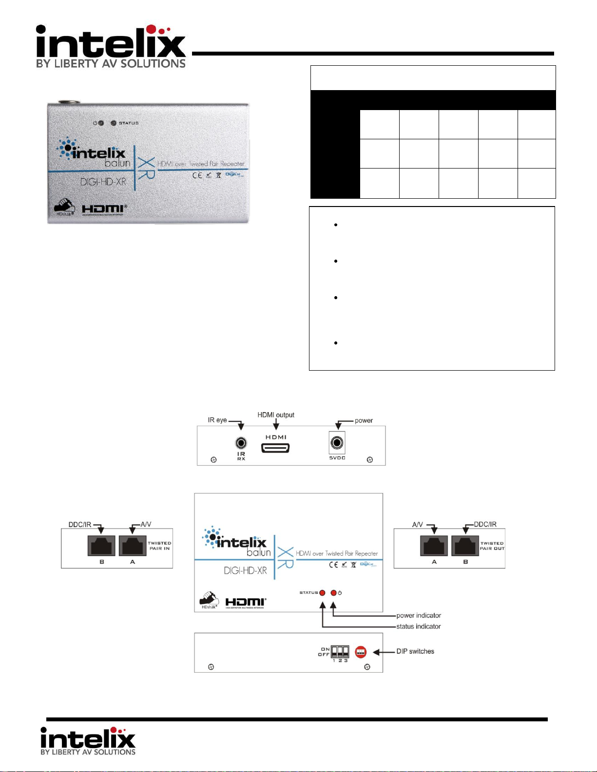
DIGI-HD-XR Installation Manual
The Intelix DIGI-HD-XR transmits HDMI and IR up to 300’ over
one or two twisted pair cables (depending on installation). In
environments with high electromagnetic interference (EMI),
shielded twisted pair cables should be used.
Built-in HDshāk® technology provides dynamic HDMI,
EDID/DDC and HDCP mode selection, guaranteeing
performance and image quality.
The DIGI-HD-XR features electrostatic discharge (ESD)
protection circuitry which safegaurds the HDMI circuit against
static electricity and other destructive stray voltage.
Page 2
8001 Terrace Ave
Suite #201
Middleton, WI 53562
Phone: 608-831-0880
Toll-Free: 866-4-MATMIX
Fax: 608-831-1833
DIGI-HD-XR Dip Switch Settings
DIP Switch
Position
Function
1
Off
Dual UTP Mode
On
Single UTP Mode
2
Off
Normal Mode
On
Compatibility Mode
3
Off
EDID FILO Mode (First In, Last Out)
On
EDID AutoMix Mode
Instructions
1. Turn off power and disconnect the audio/video
equipment by following the manufacturer’s
instructions.
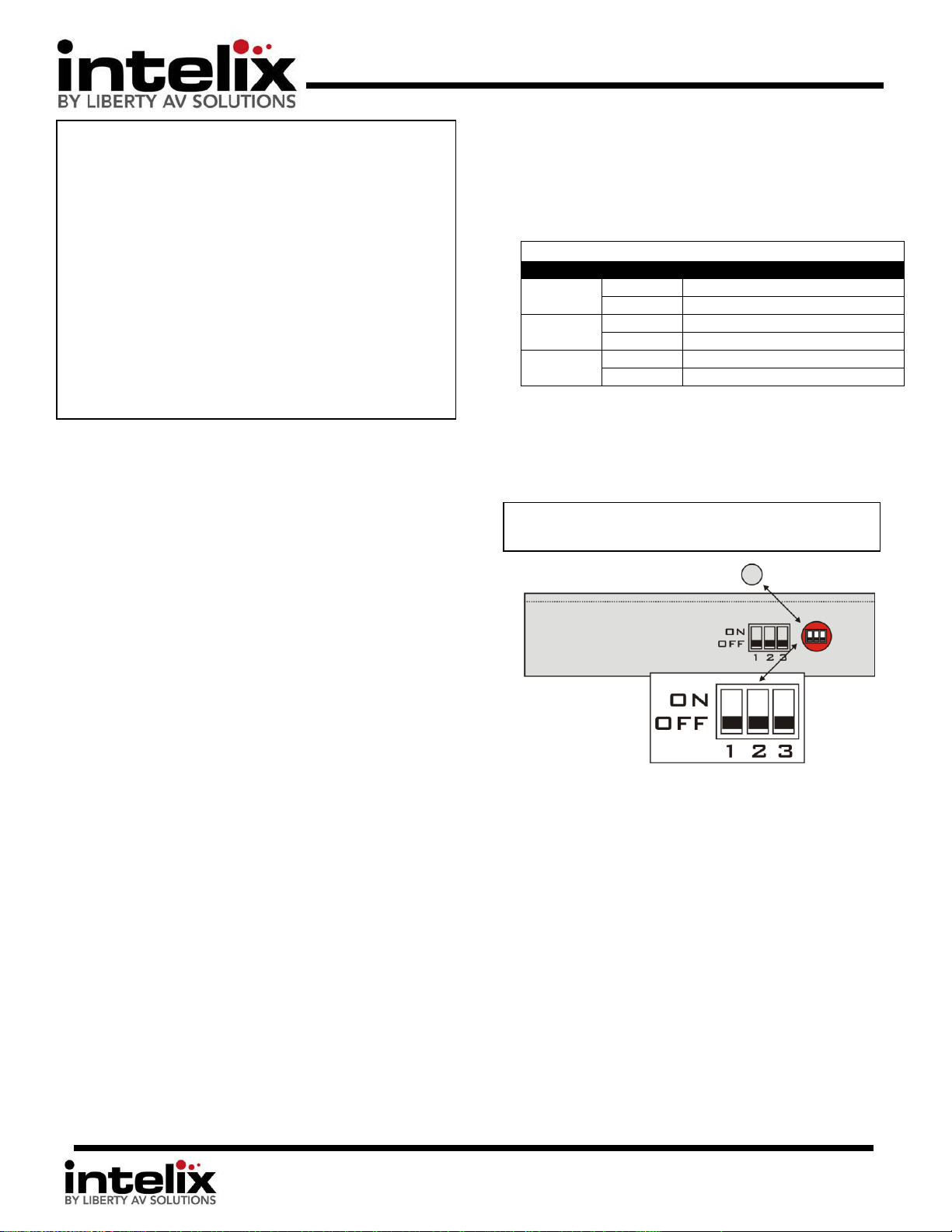
2. Adjust DIP Switches for desired mode.
3. Connect IR Eyes to DIGI-HD-XR and compatible IR
extenders. (if desired)
4. Connect IR emitters to transmitter, and apply to
source.
5. Connect all twisted pair cables.
6. Connect all HDMI cables.
Note: DIP switches are located under the cap on the
side of the unit.
b. AutoMix mode will examine EDID information of ALL
attached displays in the extender chain. The source will
then be presented with an EDID table that includes the
highest compatible resolution/audio. For instance, if you
have a [3] 1080p TVs, and [1] TV that accepts 720p as the
highest resolution, the source will transmit 720p.
DIP Switch Settings
1. Dual/Single UTP mode – Use this DIP switch to select the mode
compatible with the other extender products you are using.
a. Dual mode will allow you to utilize the included IR pickup
to transfer IR remote codes back to the source. Dual mode
will also allow you to dynamically utilize the EDID from
connected displays. You will need to attach [2] twisted pair
cables between the “A/B” Twisted Pair Input and a
compatible transmitter (Intelix HDMI twisted pair matrix
or an IR2/3 transmitter)
b. Single mode will eliminate the ability to use the IR pickup,
and will also eliminate dynamic EDID management. You
will need to attach [1] twisted pair cable between the “A”
Twisted Pair Input and a compatible transmitter (HD
Matrix or a UHR2 transmitter)
2. Normal/Compatibility Mode – Certain sources may create an
unstable video image. This may include some cable/satellite
receivers. Try this setting if you witness an image that flashes
on/off approximately every 2 seconds.
3. FILO/AutoMix Mode – Use this DIP switch to control what set of
EDID is presented to the source. This will determine what video
resolution and audio format the source will send. Either mode
are only applicable when using Single UTP mode, EDID must be
emulated by the Send Extender (or Intelix HDMI twisted pair
matrix) when using Single UTP mode.
a. FILO mode transfers all EDID from one display to the
source. This works in a First-In, Last-Out format. EDID
from the attached display of the extender that is powered
on first will be presented to the source. All other displays
in extender chain must be compatible. Removing power
from transmitter or all receivers will reset the memory.
*The DIGI-HD-XR system must be power cycled for the changes to
take effect. Please remove ALL cables from extender, change DIP
switches then reconnect.
Page 3

8001 Terrace Ave
Suite #201
Middleton, WI 53562
Phone: 608-831-0880
Toll-Free: 866-4-MATMIX
Fax: 608-831-1833
Multiple DIGI-HD-XR units may be connected
for extended distances and additional
destinations.
The DIGI-HD-XR extends HDMI distribution
distances for DIGI-HD-UHR2 extenders.
The DIGI-HD-XR extends HDMI and IR
distribution distances for DIGI-HD-IR2
extenders.
APPLICATION DIAGRAMS
Page 4

8001 Terrace Ave
Suite #201
Middleton, WI 53562
Phone: 608-831-0880
Toll-Free: 866-4-MATMIX
Fax: 608-831-1833
Troubleshooting
Symptom
Possible Solutions
No signal
Status LED is off
Verify that both ends of the twisted pair
cables use 568B crimp pattern.
Swap the twisted pair cables in the A and B
RJ45 inputs on the receive balun.
Verify HDMI cables and source and
destination HDMI ports are operational.
No signal
Verify the power supplies are connected to
both the send and receive baluns.
Verify the power LEDs on both the send
and receive units are brightly illuminated.
Unusual colors in the
video
Power off the destination device and
power it back on to force renegotiation.
Unplug and re-plug the HDMI cable from
receive balun to force renegotiation.
No signal
Screen is completely
snowy
Speckling in the video
image
Occasional signal
dropouts
Video without audio
Use shorter runs of twisted pair cabling.
Drop the HDMI signal to the next lower
resolution; i.e., decrease resolution from
1080p to 1080i, etc.
Replace the twisted pair cable with a
higher grade twisted pair cable; i.e.,
replace Cat 5e with Cat 6.
Speckling in the video
image
If the destination device is incapable of
displaying the video signal, alter the source
signal; i.e., decrease resolution from 1080p
to 1080i, etc.
Video without audio
Change source device to output PCM other
than Bitstream audio.
Enable PCM down sampling if supported by
your source device.
Technical Specifications
Maximum Distance per
Linked Unit
(Cat 5e)
1080p: 100’
1080i/720p: 200’
480i/480p/576i/576p: 200’
Maximum Distance per
Linked Unit
(Shielded Cat6a)
1080p: 150’
1080i/720p: 300’
480i/480p/576i/576p: 300’
Maximum Linked Units
5
Supported Video Resolutions
480i, 480p, 576i, 576p, 720p, 1080i, 1080p
Supported Audio
Dolby TrueHD 7.1, Dolby TrueHD 5.1,
Dolby Digital 5.1, DTS-HD Master Audio
7.1, DTS-HD Master Audio 5.1, DTS 5.1,
PCM 2.0, PCM 5.1
3D Support
Side by side half frame
Top and bottom half frame
Video Amplifier Bandwidth
1.65 Gbps
Output Video
HDMI 1.3 with HDCP
Compliancy
HDMI 1.3b
Input DDC Signal
5.0 volts p-p (TTL)
Input Video Signal
0.5 to 1.0 volts p-p
Supported IR Carrier
Frequency
36 – 40 kHz
IR Wavelength
940 nm IR
IR Frequency
38 kHz
Cabling
HDMI: One Cat5e UTP cable
HDMI & IR: Two Cat5e UTP cables
Connectors
Two (2) Shielded RJ45 inputs
Two (2) Shielded RJ45 outputs
One (1) IR input
One (1) HDMI output
Enclosure
Painted Steel
Maximum Power
Consumption
5 watts
Dimensions
110mm x 66mm x 23mm
Power Supply
5 VDC / 1A
Operating Temperature
38 ° C
Regulatory
CE, RoHS
Shipping Weight
1 lbs.
ESD Protection
16kV
Diagnostic Indicators
Status and power LEDs
Warranty
2 years
Includes
DIGI-HD-XR, Power Supply, IR eye,
Mounting brackets (2)
Twisted Pair
extender cables
must be crimped
using the T568B
standard! T568A is
not supported and
can cause video
loss.
The Intelix DIGI-HD-XR conforms to HDMI and HDCP specifications.
Intelix does not guarantee operation with devices that do not conform
to these specifications. The Intelix DIGI-HD-XR passes HDCP signals and
does not manipulate them in any way.
Distances and picture quality may be affected by cable grade, cable
quality, source and destination equipment, RF and electrical
interference, and cable patches.
 Loading...