

Page 1
DIGI-HD60C Installation Guide
Instructions
DIGI-HD60C Installation Guide
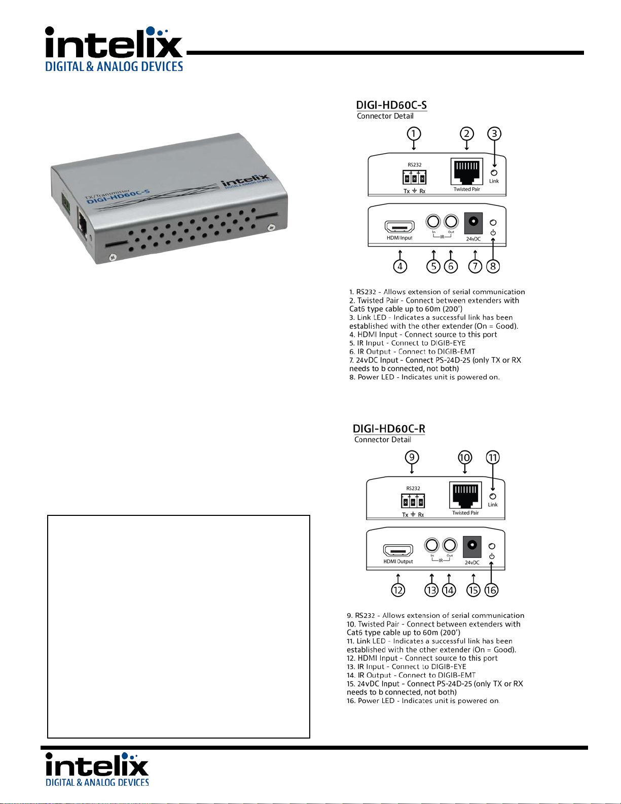
The Intelix DIGI-HD60C extends HDMI, IR, and RS232
over a single twisted pair cable. The DIGI-HD60C
supports a 1080p video signal up to 60m, as well as
3D and 4K x 2K signals up to 40m.
Built-in surge protection and diagnostic LEDs ensure
hassle-free and robust installations. Flexible power
design allows the units to be powered at either the
TX or RX end, and only one power supply is required.
The power supply (PS-24D-25) and IR accessories
(DIGIB-EMT and DIGIB-EYE) are sold separately.
The DIGI-HD60C-S and DIGI-HD60-R are designed for
use only with Intelix branded HDBaseT products.
The power circuit may not be compatible with other
HDBaseT devices and may damage them.
1. Turn off power and disconnect the audio/video
equipment by following the manufacturer’s
instructions.
2. Connect twisted pair cable between the transmitter
(DIGI-HD60C-S) and the receiver (DIGI-HD60C-R).
Ensure T568B straight-thru wiring.
3. Connect any IR or RS232 cables.
4. Connect HDMI cables between the display and the
receiver (DIGI-HD60C-R).
5. Connect HDMI cables between the source and the
transmitter (DIGI-HD60C-S).
6. Connect the power supply (PS-24D-25) to either the
transmitter or the receiver.
7. Power on attached audio/video devices.
Middleton, WI 53562
8001 Terrace Ave.
Suite #201
Phone: 608-831-0880
Toll-Free: 866-4-MATMIX
Fax: 608-831-1833
Page 2
DIGI-HD60C Installation Guide
No signal
Verify that both ends of the twisted pair cables
Link LED is blinking
Reterminate Twisted Pair cable
No signal
Verify the power supplies are connected to
Unusual colors in the
Power off the destination device and power it
receive to force renegotiation.
Important notice:
IR Extension
Cabling
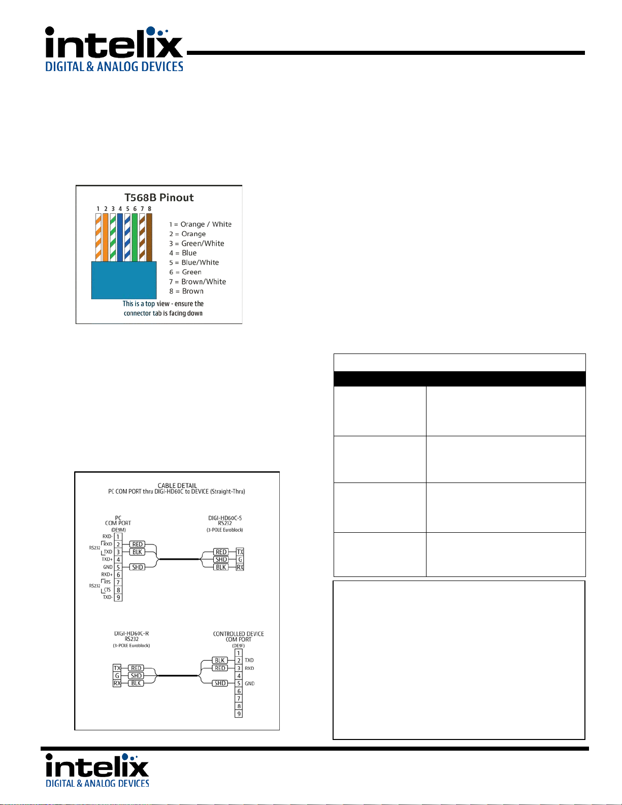
Twisted Pair Wiring - Use T568B wiring for Cat5e/6
connection between send and receive units. If using
shielded cable, be sure to use shielded connectors, and
terminate the cable drain wire to the connector shell.
RS232 Wiring – The DIGI-HD60C units include terminal blocks
that can be used for RS232 pass-through connection. You should
consult the owner’s manual of the devices you are connecting for
more information on pin out. Be sure to connect the DIGI-HD60C
RX pins to the TX pins of the connected device, and connect the
DIGI-HD60C TX pins to the RX pins of the connected device.
Connect the GROUND connection on the DIGI-HD60C to the
GROUND connection of the connected device. For your benefit,
we will illustrate how to properly pin out a straight-through
cable, using the DIGI-HD60C set to extend the signal.
You can use the IR TX and RX ports on the DIGI-HD60C to extend
the signal from your remote controls. This will allow you to
control the source, or the display, depending upon how you
connect the devices. The DIGI-HD60C supports bi-directional
communication, so you may send IR commands from the RX to
the TX and from the TX to the RX simultaneously. Be sure to use
rd
Intelix DIGIB-EYE and DIGIB-EMT products, as 3
party products
are not supported. The IR system is 5v, and you cannot connect
these ports directly to most IR distribution systems. If this is
necessary, please contact the Intelix Applications Department for
assistance.
IR RX – Connect the DIGIB-EYE to this port. The DIGIB-EYE is an IR
receiver (target). Point your IR remote at this device, and the IR
signal will be transmitted to the TX port of the other extender.
IR TX – Connect the DIGIB-EMT to this port. The DIGIB-EMT is an
IR emitter. Attach the DIGIB-EMT head over the IR window of the
device you wish to control. The DIGIB-EMT will emit IR
commands received by the DIGIB-EYE from the other extender.
Troubleshooting
Symptom Possible Solutions
Link LED is off
use T568B crimp pattern.
Verify HDMI cables and source and destination
HDMI ports are operational.
Replace Twisted Pair cable
Reduce Twisted Pair cable length
8001 Terrace Ave.
Suite #201
Middleton, WI 53562
both the send and receive baluns.
Verify the power LEDs on both the send and
receive units are brightly illuminated.
video
• Do not attempt to disassemble or alter the extender
housing. There are no user-serviceable parts inside the
unit. Doing so will void your warranty.
• To minimize the possibility of equipment damage from
electrostatic discharge (ESD), all source and destination
equipment must be powered off during installation.
• Do not connect the extender to a telecommunication
outlet wired to unrelated equipment. Doing so may
damage the unit or any connected equipment. Ensure all
connected twisted pair cabling is straight-through (pointto-point).
back on to force renegotiation.
Unplug and re-plug the HDMI cable from
Phone: 608-831-0880
Toll-Free: 866-4-MATMIX
Fax: 608-831-1833
Page 3

DIGI-HD60C Installation Guide
DIGI-HD60C Quick Start
Example Diagram
8001 Terrace Ave.
Suite #201
Middleton, WI 53562
Phone: 608-831-0880
Toll-Free: 866-4-MATMIX
Fax: 608-831-1833
Page 4

DIGI-HD60C Installation Guide
Technical Specifications
I/O Connections
HDMI
One (1) HDMI Type A Receptacle
Twisted Pair
One (1) 8P8C port (Shielded RJ45)
IR Input
One (1) 3.5mm TRS Jack
IR Output
One (1) 3.5mm TS Jack
RS232
One (1) 3-Pole Euroblock connector
24V DC Power
One (1) 5.5 mm Outside Diameter, 2.1 mm Inside Diameter Barrel (Locking)
Supported Audio, Video and Control
Maximum Video Compatibility at 60 m
Deep Color 36/30/24 Bit at 1080p
Maximum Video Compatibility at 35 m
Deep Color 48 Bit at 1080p, 3D, and 4k x 2k
Field Alternative (interlaced), Frame Packing, Line Alternative Full, Side-By-Side Half, Side-BySide Full, 2D + Depth, 2D + Depth + Graphics + Depth
Video Compliance
HDMI, HDCP, and CEC (Consumer Electronics Control)
Embedded Audio
Up to PCM 8 channel, Dolby Digital TrueHD, and DTS-HD Master Audio
Input DDC Signal
5.0 volts p-p (TTL)
Input Video Signal
0.5 to 1.0 volts p-p
IR Carrier Frequency Range
33-55kHz at 5 volts
RS232 Baud Rate
Up to 115200 baud
HDBaseT Signal Characteristics
Maximum Distance
60 m
Cable Requirements
Solid core shielded Category 5e, Category 6 or greater with TIA/EIA-568B crimp pattern
Bandwidth
10.2 Gbps
Gain
0 dB – 10 dB at 100 MHz
Resolution Range
800x600 – 1920x1200
Signal to Noise Ratio (SNR)
> 70 dB at 100 MHz over 100 m
Return Loss
< -30 dB at 5 KHz
Total Harmonic Distortion (THD)
< 0.005% at 1 KHz
Min-Max Signal Level
< 0.3 V – 1.45 Vp-p
Differential Phase Error
±10° at 135 MHz over 100 m
Chassis and Environmental
Enclosure
Painted steel
Dimensions
110mm x 76mm x 24mm (4.33 in x 2.99 in x 0.95 in)
Shipping Weight
0.5 kg (1.1 lbs.)
Operating Temperature (Environment)
0° to +40° C (+32° to +104° F)
Operating Temperature (Chassis)
31° C (88° F) (S); 38° C (100° F) (R)
Operating Humidity (Environment)
20% to 90%, Non-condensing
Storage Temperature (Environment)
-10° to +60° C (+14° to +140° F)
Storage Humidity (Environment)
20% to 90%, Non-condensing
Power, ESD, and Regulatory
Maximum Power Consumption
8 watts (S), 22 watts (R)
Power Supply (Not Included)
24vDC / 1.5 Amp
ESD Protection
15kV
Regulatory
CE, RoHS
Other
Standard Warranty
2 Years
Diagnostic Indicators
Link and power LEDs
DIGI-HD70-S, DIGI-HD60C-S, DIGI-HDE-S, FLX-BO4A, DIGI-44B, DIGI-88B, ASW-WP, DIGI-P123,
DIGI-P52
DIGI-HD60C-S Compatible Receivers
DIGI-HD70-R, DIGI-HD60C-R, DIGI-HDE-S, FLX-BI4
Included Items
Installation Guide
Accessories
Power Supply
PS-24D-25
IR Emitter
DIGIB-EMT
IR Eye
DIGIB-EYE
Universal Mounting Bracket
DIGI-PMK1
Distances and picture quality may be affected by ca ble grade, cable quality, source and destination equipment, RF and electrical interference, and cable patches.
Supported 3D Formats
DIGI-HD60C-R Compatible Transmitters
8001 Terrace Ave.
Suite #201
Middleton, WI 53562
Phone: 608-831-0880
Toll-Free: 866-4-MATMIX
Fax: 608-831-1833
 Loading...