

Page 1
DIGI-44B Installation and
Operation Guide
Rev 140813 8001 Terrace Ave Phone: 608-831-0880
Suite 201 Toll-Free: 866-462-8649
Middleton, WI 53562 Fax: 608-831-1833
Page 2

DIGI-44B Installation Guide
Please completely read and verify you understand all instructions in this manual before operating this equipment.
Keep these instructions in a safe, accessible place for future reference.
Heed all warnings.
Follow all instructions.
Do not use this apparatus near water.
Clean only with a dry cloth.
Do not install near any heat sources such as radiators, heat registers, stoves, or other apparatus (including amplifiers) that
produce heat.
Use only accessories specified or recommended by Intelix.
Explanation of graphical symbols:
o Lightning bolt/flash symbol: the lightning bolt/flash and arrowhead within an equilateral triangle symbol is
intended to alert the user to the presence of uninsulated “dangerous voltage” within the product enclosure
which may be of sufficient magnitude to constitute a risk of shock to a person or persons.
Important Safety Instructions
o Exclamation point symbol: the exclamation point within an equilateral triangle symbol is intended to alert the
user to the presence of important operating and maintenance (servicing) instructions in the literature
accompanying the product.
WARNING: TO REDUCE THE RISK OF FIRE OR ELECTRIC SHOCK, DO NOT EXPOSE THIS APPARATUS TO RAIN OR MOISTURE
AND OBJECTS FILLED WITH LIQUIDS, SUCH AS VASES, SHOULD NOT BE PLACED ON THIS APPARATUS.
Use the mains plug to disconnect the apparatus from the mains.
THE MAINS PLUG OF THE POWER CORD MUST REMAIN READILY ACCESSIBLE.
Do not defeat the safety purpose polarized or grounding-type plug. A polarized plug has two blades with one wider than
the other. A grounding-type plug has two blades and a third grounding prong. The wide blade or the third prong is provided
for your safety. If the provided plug does not fit into your outlet, consult an electrician for replacement of your obsolete
outlet. Caution! To reduce the risk of electrical shock, grounding of the center pin of this plug must be maintained.
Protect the power cord from being walked on or pinched particularly at the plugs, convenience receptacles, and the point
where they exit from the apparatus.
Do not block the air ventilation openings. Only mount the equipment per Intelix’s instructions.
Use only with the cart, stand, table, or rack specified by Intelix or sold with the equipment. When/if a cart is used, use
caution when moving the cart/equipment combination to avoid injury from tip-over.
Unplug this apparatus during lightning storms or when unused for long periods of time.
Caution! Shock Hazard. Do not open the unit.
Refer to qualified service personnel. Servicing is required when the apparatus has been damaged in any way, such as power-
supply cord or plug is damaged, liquid has been spilled or objects have fallen into the apparatus, the apparatus has been
exposed to rain or moisture, does not operate normally, or has been dropped.
2
Page 3

DIGI-44B Installation Guide
Table of Contents
Important Safety Instructions ....................................................................................................................... 2
Overview ....................................................................................................................................................... 5
Package Contents ............................................................................................................................. 5
Front Panel ....................................................................................................................................... 6
Rear Panel ........................................................................................................................................ 7
IR Remote ......................................................................................................................................... 7
Installation Instructions ................................................................................................................................ 8
Shelf Mounting Instructions ............................................................................................................ 8
Rack Mounting Instructions ............................................................................................................. 8
UTP Output Wiring ........................................................................................................................... 8
IR Port Wiring ................................................................................................................................... 8
EDID Management ........................................................................................................................................ 9
EDID Table ........................................................................................................................................ 9
Changing EDID Modes ...................................................................................................................... 9
EDID Copy Instructions .................................................................................................................... 9
Front Panel and IR Remote Operation ........................................................................................................ 10
Basic Routing .................................................................................................................................. 10
Storing Presets ............................................................................................................................... 10
Clearing Presets ............................................................................................................................. 10
Recalling Presets ............................................................................................................................ 10
IR Remote Operation ..................................................................................................................... 11
IP Address Assignment ................................................................................................................................ 12
Static IP assignment via RS232....................................................................................................... 12
DHCP IP assignment via RS232 ...................................................................................................... 13
Static IP assignment via TCP/IP ...................................................................................................... 16
DHCP IP assignment via TCP/IP ...................................................................................................... 18
Web Control ................................................................................................................................................ 19
Logging into the DIGI-44B via Web Browser. ................................................................................. 19
Changing the Password to the Web Control.................................................................................. 20
RS232 and TCP/IP Commands ..................................................................................................................... 21
RS232 Connection .......................................................................................................................... 21
3
Page 4

DIGI-44B Installation Guide
TCP/IP Connection ......................................................................................................................... 21
DIGI-44B Command Protocol ......................................................................................................... 21
Troubleshooting .......................................................................................................................................... 24
Matrix does not power on ............................................................................................................. 24
Cannot view video ......................................................................................................................... 24
Cannot hear surround sound audio ............................................................................................... 24
Cannot view 3D content ................................................................................................................ 24
Technical Specifications .............................................................................................................................. 25
DIGI-44B ......................................................................................................................................... 25
DIGIB-EMT ...................................................................................................................................... 26
DIGIB-EYE ....................................................................................................................................... 26
4
Page 5

DIGI-44B Installation Guide
Overview
The Intelix DIGI-44B is a four input by four output HDBaseT HDMI matrix switcher. The Intelix DIGI-44B
matrix improves the ease of installation compared to previous Intelix HDMI matrix switchers.
The DIGI-44B has dual outputs on each output port, allowing the same signal to be routed to the HDMI
connector and a remote destination with an HDBaseT receiver. The HDBaseT ports support 1080p HDMI
video with audio, bi-directional wide-band IR, matrix control via IR and HDCP compliance. The matrix is
HDMI compatible and supports up to 2K resolutions, Deep Color and full 3D capabilities.
The DIGI-44B can be controlled via front panel buttons, front panel IR, external IR, remote IR through
HDBaseT extenders, RS232 and Ethernet. The matrix includes a simple IR remote control to allow IR
switching. This IR remote control can be learned into universal remotes and IR based control systems.
The matrix also features a full command set for RS232 and Ethernet control with third party control
systems.
Package Contents
Please verify the following items are in the shipping box prior to installation of the DIGI-44B.
1 ea. DIGI-44B 4 Input 4 Output HDBaseT Matrix Switcher
4 ea. DIGIB-EYE IR Receivers
4 ea. DIGIB-EMT IR Transmitters
1 ea. IR Extension Cable
1 ea. 12VDC Power Supply
1 ea. Power Cable
1 ea. USB to Serial Adapter
1 ea. Infrared Remote Control with Battery (CR2025 3V)
2 ea. Rackmount Ears
6 ea. Rackmount Ears Mounting Screws
1 ea. DIGI-44B Installation and Operation Guide
5
Page 6
DIGI-44B Installation Guide
1
2
3 5 4
6 7 8
9
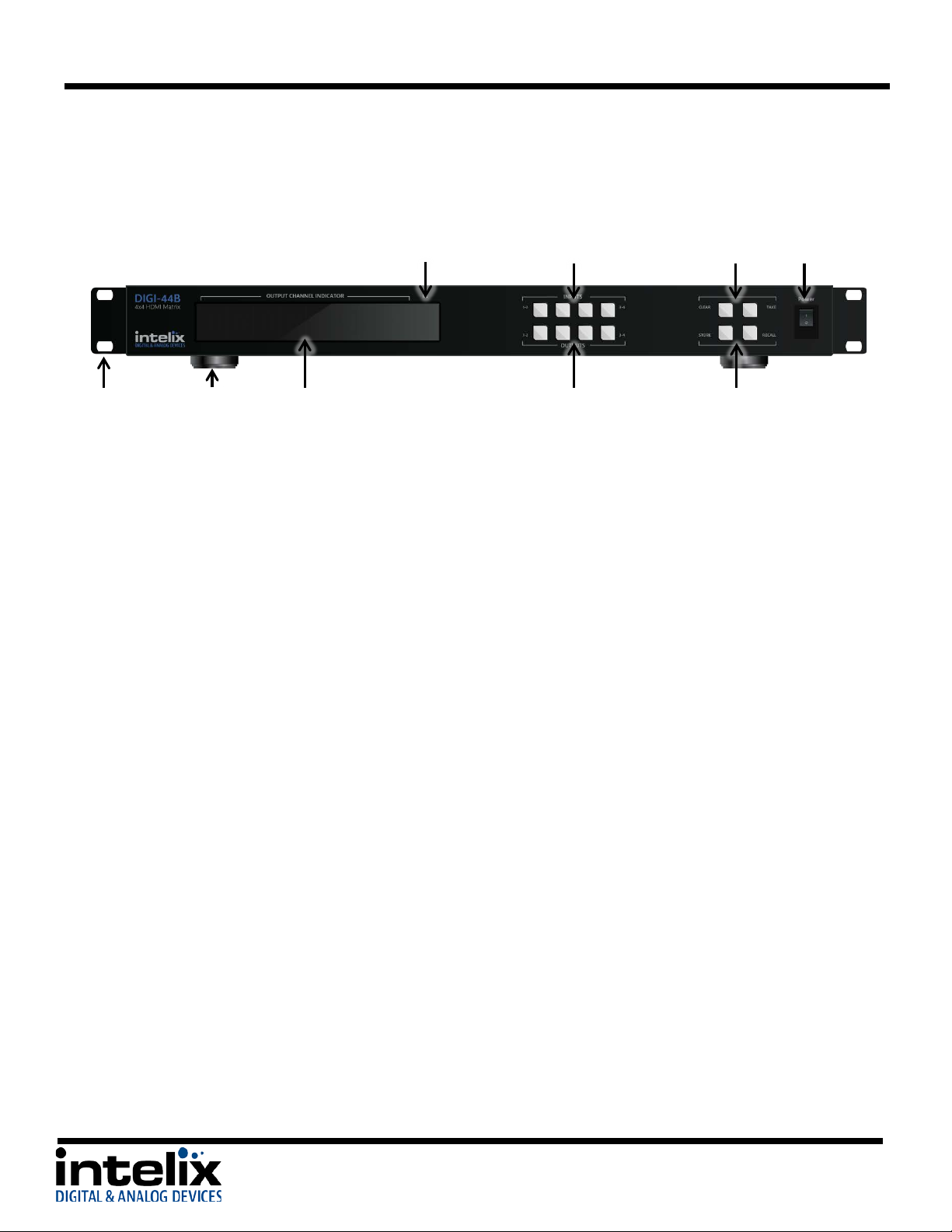
Front Panel
1 - IR Receiver – For use with the included IR remote.
2 - Input Buttons –Buttons labeled “1-2” and “3-4”.
3 - Preset Buttons (Top Row) –Buttons labeled “CLEAR” and “TAKE”.
CLEAR – Used to cancel the current input selection.
TAKE – Used to make the changes active.
4 - Power Switch –Switch to toggle the power to the matrix.
5 - Rack Ears – Optional rack ears for rack mounting the DIGI-44B in an equipment rack.
6 - Chassis Feet –Factory installed feet for shelf top installations.
7 - LED Display – Routing information is displayed.
8 - Output Buttons – Buttons labeled “1-2” and “3-4”.
9 - Preset Buttons (Bottom Row) –Buttons labeled “STORE” and “RECALL”.
STORE – Used to save a preset to memory.
RECALL – Used to load a preset from memory.
Explanation of use for the front panel control is located in the section Front Panel and IR Remote Operation
(page 10).
6
Page 7
DIGI-44B Installation Guide
10
1
1
2 3 4
5
6
7
8
9
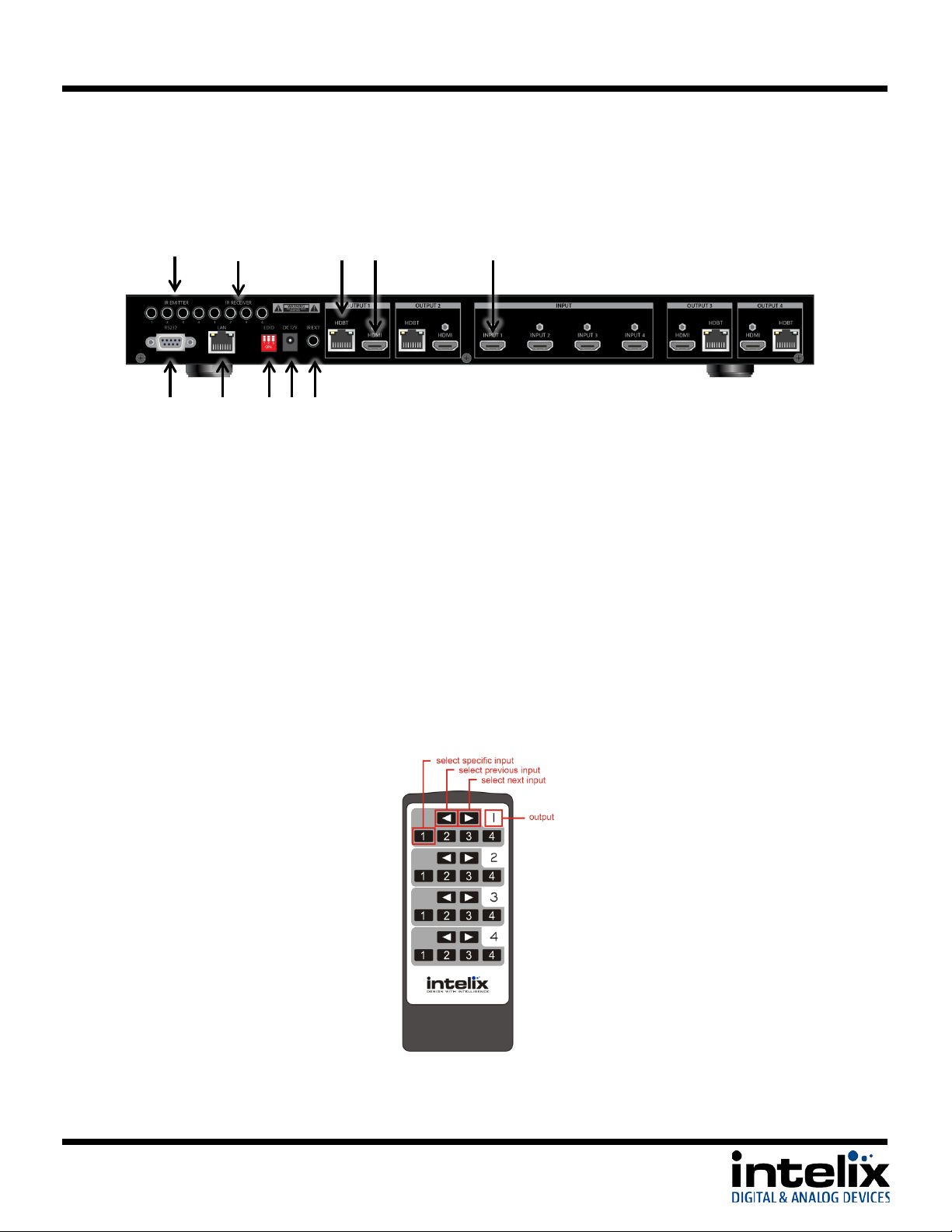
Rear Panel
1 - Emitter Ports – IR emitters to control HDMI sources in the rack.
2 - IR Receiver Ports – IR receiver ports to send IR signals to the remote HDBaseT receivers.
3 - Outputs: HDBaseT Lite extended output – 70m max
4 - Outputs: HDMI local output
5 - Inputs: HDMI local input
6 - RS232 Control – serial communication for third party control.
7 - Ethernet – web server and UDP control.
8 - EDID DIP switches - select the EDID management mode.
9 - DC Power Input – 12vDC/5a power inlet.
10 - IR Extended Input – input for extending the local IR input.
IR Remote
The included IR remote performs routing functions available on the front panel of the DIGI-44B.
7
Page 8

DIGI-44B Installation Guide
Shelf Mounting Instructions
The DIGI-44B comes with pre-installed feet and can be shelf mounted directly out of the box.
Rack Mounting Instructions
The DIGI-44B requires one rack unit (1 RU) of space. At least 2 inches of free air space is required on both
sides of the DIGI-44B for proper side ventilation. Avoid mounting the DIGI-44B near a power amplifier or
any other source of significant heat. It is recommended that you leave an empty rack space above and
below the DIGI-44B for additional cooling.
Remove the feet from the bottom of the chassis by unscrewing the 4 Phillips head screws inside of the
feet. Set feet aside. Attach the rack ears using the 6 Phillips head screws provided. Mount the DIGI-44B
in the desired location within the rack enclosure.
Installation Instructions
UTP Output Wiring
A compatible HDBaseT receiver is required to extend the
output signals over Twisted Pair cabling. To connect the
DIGI-44B to a compatible receiver, a Cat 6 or greater cable
with a TIA-568B crimp termination on the RJ45 connector
must be used. The Cat 6 cable must not exceed 40 meters
for 3D content. The Cat 6 cable must not exceed 70 meters
for 2D content.
IR Port Wiring
To use the IR extension capabilities of the DIGI-44B, the DIGIB-EYE (wideband IR receiver) and DIGIB-EMT
(wideband IR emitter) will need to be connected to the appropriate IR ports. DIGIB-EYE’s should be
connected to the IR RECEIVER ports and DIGIB-EMT’s should be connected to the IR EMITTER ports. After
connecting the DIGIB-EMT to the IR output, mount the IR emitter to the appropriate source gear.
*Note: Third party IR components such as connecting blocks or base stations are not compatible with the
DIGI-44B ports
8
Page 9
DIGI-44B Installation Guide
EDID Setting
DIP switch 1
DIP switch 2
DIP switch 3
EDID Copy
0 (Down)
0 (Down)
0 (Down)
No Function
0 (Down)
0 (Down)
1 (Up)
1080p 7.1ch Audio
0 (Down)
1 (Up)
0 (Down)
1080p 5.1ch Audio
0 (Down)
1 (Up)
1 (Up)
1080i Stereo
1 (Up)
0 (Down)
0 (Down)
1080p Stereo (Default)
1 (Up)
0 (Down)
1 (Up)
1080p 3D Video / Stereo Audio
1 (Up)
1 (Up)
0 (Down)
No Function
1 (Up)
1 (Up)
1 (Up)
EDID Management
HDMI signals require communication between the Source and Display equipment. The Display provides
information to the source on supported formats for video and audio. The information that is passed from
display to source is referred to as EDID. The DIGI-44B includes common EDID’s for increased compatibility.
The matrix also features an EDID copy mode that can be used when other EDID’s do not meet the
installation requirements.
The default EDID for the DIGI-44B is 1080p with stereo audio. All EDID modes are outlined in the table
below:
EDID Table
Changing EDID Modes
To change the EDID mode on the matrix:
1. Power down the DIGI-44B matrix.
2. Change the dipswitch to the desired EDID mode (outlined in the table above).
3. Power on the DIGI-44B matrix. The new EDID has been stored at all the inputs.
EDID Copy Instructions
To copy an EDID from a specific output to a specific input (for example, output 3 to input 2):
1. Power down the DIGI-44B matrix.
2. Change the dipswitches to 0, 0, 0 (Down, Down, Down).
3. Connect the HDMI cable of the display to the desired output on the DIGI-44B matrix (output 3).
You can use either HDMI or HDBT outputs, but only connect one at a time for copy operation.
4. Power on the DIGI-44B matrix.
5. Using the front panel, setup the AV route, from the input you want the EDID to be copied to, to
the output you connected the display you want to copy. (input 2 to output 3)
6. Press and Hold the Output Button connected in Step 3 (output 3).
7. Wait for Display to show “CPY” and “OK”.
8. EDID has been successfully copied.
9
Page 10

DIGI-44B Installation Guide
Front Panel and IR Remote Operation
Basic Routing
To set a single route using the front panel of the DIGI-44B:
1. Press the desired input button (source).
2. Press the desired output button (display).
3. Front panel will flash the New Input Number.
4. Press the “Take” button
To set multiple routes using the front panel of the DIGI-44B:
1. Press the desired input button (source).
2. Press the desired output button(s) (display). You can choose any or all outputs.
3. Front panel will flash the New Input Number(s).
4. Press the “Take” button.
Storing Presets
To store a preset:
1. Using the Basic Routing instructions setup the desired routing.
2. Press the “Store” button. The Input LED’s will begin flashing.
3. Press and Hold the input button for the desired preset location.
For example to store the current route into Preset #2 then press and hold input 2 button.
4. Continue to hold the input button until the LEDs stop flashing. When the LEDs stop flashing your
preset has been stored.
10
Clearing Presets
To clear a preset repeat the “To store a preset” procedure to overwrite the current preset.
Recalling Presets
To recall a preset:
1. Press the “Recall” button.
2. The Input LED’s will begin flashing.
3. Press the input button for the desired preset location.
For example to recall Preset #2 then press the input 2 button.
4. The LED’s will stop flashing, the HDMI routes are completed and the display updates to show the
new routing information.
Page 11

DIGI-44B Installation Guide
IR Remote Operation
The IR remote includes buttons for Next Input, Previous Input, and selection of a
specific input.
1. Determine which output you wish to change.
2. On the determined output, select the desired input number.
3. On the determined output, cycle through the inputs by pressing the
previous input or next input button.
11
Page 12

DIGI-44B Installation Guide
The DIGI-44B ships from the factory with a default IP address of 192.168.0.178. You can change this IP
address to a different static IP address or to DHCP using the DIGI-44B Docklight configuration file, which
can be found on the Intelix website.
Static IP assignment via RS232
The Static IP address can be changed using RS232
1. Download Docklight and the DIGI-44B from the Intelix website.
2. Connect the included USB -> RS232 adapter to an open USB port on your computer, or if you have
a serial port, connect a straight through serial cable. When using the
USB->RS232 adapter for the first time, device drivers should be automatically installed.
3. Open the Docklight Configuration File.
4. Confirm the Docklight communication settings
(Docklight -> Tools -> Project Settings) match the
device. 9600/8/n/1 on the COM port named USB Serial
Port (or COM 1 if using your computer’s serial port
instead of the adapter.
5. Start Communication.
IP Address Assignment
12
Page 13

DIGI-44B Installation Guide
6. Turn the power to the DIGI-44B on – after 5 seconds, the DIGI-44B will
send some lines of information you can see in the communications
window. This confirms that you are communicating properly.
7. In the “Send Sequences” window, press the Set IP (Use
Wildcards) button.
8. Type the desired IP address in 3 byte sequences,
pressing the Enter key on your keyboard after each
sequence.
9. Verify that the IP address changed
in the communication window. .
*Note – it can take 5-10 seconds
for the unit to report back the
confirmed change.
DHCP IP assignment via RS232
You can change the IP mode to DHCP using RS232
1. Download Docklight and the DIGI-44B from the Intelix website.
2. Connect the included USB -> RS232 adapter to an open USB port on your computer, or if you have
a serial port, connect a straight through serial cable. When using the
USB->RS232 adapter for the first time, device drivers should be automatically installed.
3. Open the Docklight Configuration File.
13
Page 14

DIGI-44B Installation Guide
14
Page 15

DIGI-44B Installation Guide
4. Confirm the Docklight communication settings (Docklight -
> Tools -> Project Settings) match the device. 9600/8/n/1
on the COM port named USB Serial Port (or COM 1 if using
your computer’s serial port instead of the adapter.
5. Start Communication.
6. Turn the power to the DIGI-44B on – after 5 seconds, the
DIGI-44B will send some lines of information you can see in
the communications window. This confirms that you are
communicating properly.
7. In the “Send Sequences” window, press the Set IP Mode
DHCP button
8. Verify that the IP address changed in the
communication window. *Note – it can take
5-10 seconds for the unit to report back the
confirmed change.
15
Page 16

DIGI-44B Installation Guide
Static IP assignment via TCP/IP
The Static IP address can be changed using TCP/IP
1. Download Docklight and the DIGI-44B from the Intelix website.
2. Connect a network crossover cable (not included) between your computer and the DIGI-44B LAN
Port.
3. Change the IP address of your computer to fit in the same subnet as the DIGI-44B current IP
address. The unit’s default IP address is 192.168.0.178, so set your IP address to 192.168.0.177
for first time connection. To change your computer’s IP address in Windows7, follow this path
(START Menu -> Control Panel -> Network and
Internet -> Network and Sharing Center)
a. Select “Local Area Connection”
b. Select “Properties”
4. Select “Internet Protocol Version 4 (TCP/IPv4)”,
then select “Properties”.
16
Page 17

DIGI-44B Installation Guide
5. Select “Use the following IP address”, and then enter the
IP address you would like your computer to become.
Then select “OK”
6. Open the Docklight Configuration File
7. Confirm the Docklight communication settings
(Docklight -> Tools -> Project Settings) match
the DIGI-44B. *Note – add a colon and the
number [23] after the IP address you enter to
signify the communication port.
.
8. Start Communication.
9. Turn the power to the DIGI-44B on – after 5 seconds, the DIGI-
44B will send some lines of information you can see in the
communications window. This confirms that you are
communicating properly.
17
Page 18

DIGI-44B Installation Guide
10. In the “Send Sequences” window, press the Set IP
(Use Wildcards) button.
11. Type the desired IP address in 3 byte
sequences, pressing the Enter key on your
keyboard after each sequence.
12. Verify that the IP address changed
in the communication window. .
*Note – it can take 5-10 seconds for
the unit to report back the
confirmed change.
18
DHCP IP assignment via TCP/IP
Setting the DIGI-44B to DHCP while connected via TCP/IP is not recommended.
Page 19

DIGI-44B Installation Guide
Web Control
Logging into the DIGI-44B via Web Browser.
The DIGI-44B routing can be controlled through a standard web browser.
1. Open up Internet Explorer (Firefox, Chrome, and Safari crop the configuration options).
2. Type the IP Address of the matrix into the Web Browser’s address bar. The Login screen will load.
(The unit leaves the factory with a default IP address of 192.168.0.178)
3. The Default password is “0000000000” (ten zeroes).
4. Press the LOGIN button. A “Welcome” screen will briefly be shown before forwarding to the
control page below:
5. Clicking the buttons after each output changes the HDMI routing accordingly.
*Note: Do not select “Update Firmware” unless instructed by Intelix Support to do so. This puts the unit
into a bootloader mode, which can be cancelled by power cycling the DIGI-44B.
19
Page 20

DIGI-44B Installation Guide
Changing the Password to the Web Control
1. Log into the Web Control utility by using the instructions above.
2. Click the “Change Password” link at the bottom of the Web Control screen. The following screen
will appear:
20
3. Type in the Old Password in the “Old Password” filed.
4. Type in the New Password in the “New Password” field.
5. Confirm the New Password in the “Confirm Password” field.
6. Click “OK”.
7. A Password Change Success page will be briefly displayed before forwarding to the Login page.
Page 21

DIGI-44B Installation Guide
Output 1 Commands
Function
Command
Response
Select Input 1
cir 09<CR><LF>
s10<CR><LF>
The updated status for output 1. Represented as an ASCII
Select Input 2
cir 1D<CR><LF>
s11<CR><LF>
Select Input 3
cir 1F<CR><LF>
s12<CR><LF>
Select Input 4
cir 0D<CR><LF>
s13<CR><LF>
Select Input Up
cir 41<CR><LF>
new route
Select Input Down
cir 57<CR><LF>
new route
Output 2 Commands
Function
Command
Response
Select Input 1
cir 17<CR><LF>
s20<CR><LF>
The updated status for output 2. Represented as an ASCII
3 = input 4
Select Input 2
cir 12<CR><LF>
s21<CR><LF>
Select Input 3
cir 59<CR><LF>
s32<CR><LF>
Select Input 4
cir 08<CR><LF>
s43<CR><LF>
Select Input Up
cir 11<CR><LF>
new route
Select Input Down
cir 1B<CR><LF>
new route
RS232 and TCP/IP Commands
RS232 Connection
The RS232 control port requires a standard straight-through serial cable for
operation. The default settings for the RS232 port are:
- 9600 baud
- 8 Data Bits
- 1 Stop Bit
- Parity = none
TCP/IP Connection
TCP/IP Settings: User defined IP address, port 23 (The unit leaves the factory with a default IP address of
192.168.0.178)
DIGI-44B Command Protocol
Important Note: Be sure to include a carriage return after the command line when the command includes the “<CR><LF>” suffix.
Also, there is a space between “cir” and the code, which is required.
RS232 & TCP/IP Routing Commands
string in the format of “sXY” where:
• X is the output channel
• The value of Y maps as follows:
0 = input 1
1 = input 2
2 = input 3
3 = input 4
string in the format of “sXY” where:
• X is the output channel
• The value of Y maps as follows:
0 = input 1
1 = input 2
2 = input 3
21
Page 22

DIGI-44B Installation Guide
Output 3 Commands
Function
Command
Response
Select Input 1
cir 5E<CR><LF>
s30<CR><LF>
The updated status for output 3. Represented as an ASCII
3 = input 4
Select Input 2
cir 06<CR><LF>
s31<CR><LF>
Select Input 3
cir 05<CR><LF>
s32<CR><LF>
Select Input 4
cir 03<CR><LF>
s33<CR><LF>
Select Input Up
cir 48<CR><LF>
new route
Select Input Down
cir 55<CR><LF>
new route
Output 4 Commands
Function
Command
Response
Select Input 1
cir 18<CR><LF>
s40<CR><LF>
The updated status for output 4. Represented as an ASCII
3 = input 4
Select Input 2
cir 44<CR><LF>
s41<CR><LF>
Select Input 3
cir 0F<CR><LF>
s42<CR><LF>
Select Input 4
cir 51<CR><LF>
s43<CR><LF>
Select Input Up
cir 40<CR><LF>
new route
Select Input Down
cir 07<CR><LF>
new route
Misc. Commands
Function
Command
Response
Get Device Type
br <space>
aDIGI-44B
ASCII string containing the letter
device
Get Device Status
bc <space>
Ex:
ASCII string in the format of:
where Y is the
Each segment is
s4 = output 4
Get IP Mode and
gipm<CR><LF>
Static IP Ex:
ASCII string containing
“ipm<space>” followed by IP
mode, the IP address,
DHCP IP Ex:
RS232 & TCP/IP System Commands
string in the format of “sXY” where:
• X is the output channel
• The value of Y maps as follows:
0 = input 1
1 = input 2
2 = input 3
string in the format of “sXY” where:
• X is the output channel
• The value of Y maps as follows:
0 = input 1
1 = input 2
2 = input 3
Address
22
s10<CR><LF>
s21<CR><LF>
s32<CR><LF>
s43<CR><LF>
ipm sip 192 168 001 114 <CR><LF>
ipm dhc 192 168 001 101 <CR><LF>
“a” followed by the name of the
“s1Ys2Ys3Ys4Y”
input source being routed to each
output.
separated by a <CR><LF>.
The value of Y maps as follows:
0 = input 1
1 = input 2
2 = input 3
3 = input 4
The output channels map as
follows:
s1 = output 1
s2 = output 2
s3 = output 3
<space><CR><LF>
The value of the IP mode map as
follows:
sip = Static IP Mode
dhc = Dynamic IP Mode
Page 23

DIGI-44B Installation Guide
Misc. Commands
Function
Command
Response
Set IP Mode - DHCP
dhc <CR><LF>
“DHCP<CR><LF>”
Set IP Mode - Static
sip www xxx yyy zzz<CR><LF>
separated by a
sip 192 168 001 114<CR><LF>
Ex:
ASCII string that includes the IP
of communications caused by
Where:
st
nd
octet
rd
octet
octet
www = 1
xxx = 2
yyy = 3
zzz = 4th octet
Each octet is
<space>.
Ex: Set IP to 192.168.1.114:
IP 192 168 001 114<CR><LF>
address set by the command.
“IP www xxx yyy zzz<CR><LF>”
***When using this command via
a TCP/IP connection, the response
may be truncated due to the loss
changing the IP address.
23
Page 24

DIGI-44B Installation Guide
Matrix does not power on
Verify power outlet is active.
Verify continuity in power cable.
Cannot view video
Copy EDID from output to input.
Verify twisted pair cable does not exceed 70 meters.
Disable CEC in source and display devices.
Troubleshooting
Cannot hear surround sound audio
Copy EDID from output to input.
Verify output can broadcast surround sound audio.
Verify source device is configured to output surround sound audio.
Cannot view 3D content
Copy EDID from output to input.
Verify display is 3D compatible.
Verify source device can output 3D content.
Verify twisted pair cable does not exceed 40 meters.
24
Page 25

DIGI-44B Installation Guide
I/O Connections
HDMI Inputs
Four (4) HDMI Type A Receptacle (1 per input)
HDMI Outputs
Four (4) HDMI Type A Receptacle (1 per output)
HDBaseT Outputs
Four (4) 8P8C port (Shielded RJ45) (1 per output)
IR Input
Four (4) 3.5 mm jack (TRS) (1 per input)
IR Output
Four (4) 3.5 mm jack (TS) (1 per output)
IR Extension Input
One (1) 3.5 mm jack (TRS)
12V DC Power
One (1) 5.5 mm Outside Diameter, 2.1 mm Inside Diameter Barrel
Control, Rear Panel
RS232 via DE-9, TCP/IP via 8P8C, IR via 3.5mm TRS
Control, Front Panel
Push Button, IR
DIP Switch
Three switch DIP
Supported Audio, Video, and Control
HDTV Video Resolutions
480i, 480p, 576i, 576p, 720p, 1080i, 1080p
VESA Video Resolutions
Up to 1920x1200
Maximum Video Compatibility at 70 m
Deep Color 36/30/24 Bit at 1080p
Maximum Video Compatibility at 40 m
Deep Color 48 Bit at 1080p and 3D
Supported 3D Formats
Field Alternative (interlaced), Frame Packing, Line Alternative Full, Side-By-Side Half, Side-BySide Full, 2D + Depth, 2D + Depth + Graphics + Depth
DIP Switch Modes
1080i/2.0, 1080p 3D/2.0, 1080p/2.0, 1080p/5.1, 1080p/7.1, Copy and Use EDID from Display
Video Compliance
HDMI, HDCP, and CEC (Consumer Electronics Control)
Embedded Audio
Up to PCM 8 channel, Dolby Digital TrueHD, and DTS-HD Master Audio
Input DDC Signal
5.0 volts p-p (TTL)
Input Video Signal
0.5 to 1.0 volts p-p
IR Carrier Frequency Range
33-55kHz at 5 volts
Ethernet
100BaseT
RS232 Baud Rate
9600 baud
HDBaseT Signal Characteristics
Maximum Distance
70 m
Cable Requirements
Solid core shielded Category 5e, Category 6 or greater with TIA/EIA-568B crimp pattern
Bandwidth
10.2 Gbps
Gain
0 dB – 10 dB at 100 MHz
Signal to Noise Ratio (SNR)
> 70 dB at 100 MHz over 100 m
Return Loss
< -30 dB at 5 KHz
Total Harmonic Distortion (THD)
< 0.005% at 1 KHz
Min-Max Signal Level
< 0.3 V – 1.45 Vp-p
Differential Phase Error
±10° at 135 MHz over 100 m
Chassis and Environmental
Enclosure
Painted Steel
Dimensions
440 mm x 230 mm x 44 mm (17.32 in x 9.06 in x 1.73 in)
Rack Spacing
1 RU
Shipping Weight
3.72 kg (8.2 lbs)
Operating Temperature
0° to +40° C (+32° to +104° F)
Operating Humidity
20% to 90%, Non-condensing
Storage Temperature
-10° to +60° C (+14° to +140° F)
Storage Humidity
20% to 90%, Non-condensing
Power, ESD, and Regulatory
Power Supply Input
100V-240VAC / 1.8A
Power Supply Output
12V DC / 5A
Power Consumption
60 watts (max)
ESD Protection
15kV
DIGI-44B Regulatory
CE, RoHS
Power Supply Regulatory
UL, FCC, CCC, CE, RoHS
Other
Warranty
2 years
Diagnostic Indicators
LED output status and power LED
Included Accessories
Installation Guide, IR Remote, IR Emitter (4 ea), IR Receiver (4 ea), USB/RS232 adaptor, US
Power Cable and Power Supply, Mounting Brackets with screws, Chassis Feet
Compatible Receivers (A/V Only)
DIGI-HD70-R
Compatible Receivers (A/V and IR)
DIGI-HDE-R, DIGI-HD60C-R
DIGI-44B
Technical Specifications
25
Page 26

DIGI-44B Installation Guide
Signal Characteristics
Wide-Band Infrared (IR)
30 KHz to 56 KHz at 5V DC reference
Physical Characteristics
Material, Emitter Housing
Deep red translucent plastic
Dimensions, Emitter Housing
6 mm x 9.5 mm x 15 mm (0.24 in. x 0.37 in. x 0.59 in.)
Cable Length
2 m (6.56 ft)
Cable Connector
3.5 mm (1/8 in.) mono (TS) plug
Shipping Weight
0.5 lbs. (0.23kg)
Other
Warranty
2 years
What’s in the Box
(4) DIGIB-EMT
Compatible Devices
FLX-BI4, FLX-BO4, DIGI-HDE-S, DIGI-HDE-R, DIGI-HD70C-S, DIGI-HD70C-R, DIGI-
VGASD2-T4, DIGI-VGASD2-T8
Signal Characteristics
Wide-Band Infrared (IR)
30 KHz to 56 KHz at 5V DC reference
Physical Characteristics
Material, Emitter Housing
Black plastic housing; smoke gray lens housing
Dimensions, Emitter Housing
13.5 mm x 9 mm x 29.5 mm (0.53 in. x 0.35 in. x 1.16 in.)
Cable Length
1 m (3.28 ft)
Cable Connector
3.5 mm (1/8 in.) stereo (TRS) plug
Shipping Weight
0.5 lbs. (0.23kg)
Other
Warranty
2 years
What’s in the Box
(1) DIGIB-EYE (hardware not included)
Compatible Devices
FLX-BI4, FLX-BO4, DIGI-HDE-S, DIGI-HDE-R, DIGI-HD70C-S, DIGI-HD70C-R, DIGIHD-IR3-S, DIGI-HD-IR3-R, DIGI-HD-IR3-WP-S, DIGI-HD-IR3-WP-R
DIGIB-EMT
HD-IR3-S, DIGI-HD-IR3-R, DIGI-HD-IR3-WP-S, DIGI-HD-IR3-WP-R, DIGI-HD-8X8,
DIGI-HD-4X8, DIGI-HD-4X4, DIGI-HD-4X2, DIGI-VGASD2-S, DIGI-VGASD2-R, DIGI-
DIGIB-EYE
26
Page 27

DIGI-44B Installation Guide
This page intentionally left blank.
27
Page 28

DIGI-44B Installation Guide
Please contact us with your questions and comments.
Thank you for your purchase.
Intelix
8001 Terrace Ave, Ste 201
Middleton, WI 53562
Phone: 608-831-0880
Toll Free: 866-462-8649
Fax: 608-831-1833
www.intelix.com
intelix@intelix.com
28
 Loading...