

Page 1

AMIX Series
Automatic Mixers
Installer’s Manual
AMIX-4
AMIX-8
Page 2

AMIX Series Automatic Mic/Line Mixer User Manual
Warranty
All Intelix products are guaranteed against malfunction due to defects in materials or workmanship for
two years after date of purchase. If a malfunction does occur during the specified period, the defective
product will be repaired/replaced, at Intelix’s option, without charge. Furthermore, the “Fresh Start”
program ensures that a product which has been repaired/replaced is itself guaranteed for an additional
two years.
This warranty does not cover: 1) Malfunction resulting from use of the product other than as specified
in the user manual; 2) Installation specific wiring; 3) Malfunction resulting from abuse or misuse of the
product; 4) Exterior chassis appearance; 5) Malfunction occurring after repairs have been made by
anyone other than Intelix or any of its authorized service representatives; 6) Acts of nature; 7) Optional
embedded software upgrades or updates.
All repair and service of Intelix products should only be provided by qualified service personnel. Please
contact Intelix for a list of authorized service agents. Other attempts at service or repair will void the
warranty. Warranty service is only offered after a return authorization number has been generated by an
authorized Intelix representative.
Toll Free Service Number: 1-866-4-MATMIX
Intelix LLC
2222 Pleasant View Road
Middleton, WI 53562
Phone: (608) 831-0880
Fax: (608) 831-1833
www.intelix.com
intelix@intelix.com
Copyright Intelix 2004. All rights reserved.
2
April 2004
intelix
Page 3

AMIX Series Automatic Mic/Line Mixer User Manual
Table of Contents
1.0 Introduction................................................................................................... 7
1.0 Introduction......................................................................................................................... 7
1.1 Safety Instructions............................................................................................................... 7
1.2 Maintenance Guidelines....................................................................................................... 7
1.3 Quick Start for the AMIX Mixer.......................................................................................... 8
1.3.1 Unpack and connect.............................................................................................. 8
1.3.2 Power and set-up................................................................................................... 8
1.3.3 Fine tuning............................................................................................................ 8
1.3.4 Optional special features activation........................................................................ 8
1.3.5 Linking multiple mixers......................................................................................... 8
2.0 Panel Descriptions......................................................................................... 9
2.0 Panel Descriptions................................................................................................................ 9
2.1 Mixer Front Panel................................................................................................................ 9
2.2 Mixer Front Panel AccessWindow........................................................................................ 10
2.3 Mixer Rear Panel................................................................................................................. 11
3.0 AMIX Functions............................................................................................ 12
3.0 AMIX Functions.................................................................................................................. 12
3.1 Threshold Sensitive Gating................................................................................................... 12
3.2 Number of Open Microphones............................................................................................. 12
3.3 Hold Time Potentiometer.....................................................................................................12
3.4 Off-Attenuation Amount Potentiometer................................................................................ 12
3.5 User Selectable Modes of Operation.................................................................................... 13
3.5.1 Last mic on............................................................................................................ 13
3.5.2 First come, first served.......................................................................................... 13
3.6 Priority Override.................................................................................................................. 13
3.7 AMIX Channel Exclusion..................................................................................................... 14
3.8 AMIX Software Version.......................................................................................................14
4.0 Installation..................................................................................................... 15
4.0 Installation of the AMIX Mixer............................................................................................ 15
4.1 Unpack, Connect, and Power-up.......................................................................................... 15
4.2 Connect Inputs..................................................................................................................... 15
4.3 Channel 4 or 8...................................................................................................................... 15
4.4 Connect Output................................................................................................................... 16
4.5 Power Up............................................................................................................................. 16
4.5.1 Connect the mixer power supply............................................................................ 16
4.5.2 Power up the mixer................................................................................................ 16
intelix
3
Page 4

AMIX Series Automatic Mic/Line Mixer User Manual
5.0 Gain Structure................................................................................................. 17
5.0 Gain Structure....................................................................................................................... 17
5.1 Setting the AMIX Mixer Channels......................................................................................... 18
6.0 Mixer Fine Tuning.......................................................................................... 19
6.0 Mixer Fine Tuning................................................................................................................. 19
6.1 Low Cut Switch.................................................................................................................... 19
6.2 Phantom Power Switch......................................................................................................... 19
6.3 Aphex Aural Exciter............................................................................................................... 19
6.4 Output Limit Switch.............................................................................................................. 19
6.5 Select Bar Graph Readout..................................................................................................... 20
6.6 The Ground Lift Jumper........................................................................................................ 20
6.7 Rack the Mixer...................................................................................................................... 20
7.0 Setting AMIX Functions................................................................................. 21
7.0 Setting AMIX Functions........................................................................................................ 21
7.1 Channel Isolation................................................................................................................... 22
7.2 Fine Tuning AMIX Functions................................................................................................ 22
8.0 External Control............................................................................................. 23
8.0 External Control.................................................................................................................... 23
8.1 The Connectors..................................................................................................................... 23
8.2 DC Control........................................................................................................................... 24
8.2.1 Remote volume control.......................................................................................... 24
8.2.2 Connecting a remote volume control....................................................................... 24
8.2.3 Remote mute control.............................................................................................. 24
8.2.3.1 Wiring an external mute switch................................................................. 24
8.2.3.2 Wiring an external combination mute switch and volume control.............. 25
8.3 Circuit Board Map................................................................................................................. 25
8.4 Master Output Insert Patching...............................................................................................26
9.0 Passive Mixer Linking.................................................................................... 27
9.0 Passive Mixer Linking........................................................................................................... 27
9.1 Making the Cables................................................................................................................. 27
9.2 Connecting the Cables........................................................................................................... 27
10.0 AMIX-LINK Module.................................................................................... 28
10.0 AMIX-LINK Module.......................................................................................................... 28
10.1 Quick Start for AMIX-LINK............................................................................................... 29
4
intelix
Page 5

AMIX Series Automatic Mic/Line Mixer User Manual
10.1.1 Installing the AMIX-LINK................................................................................... 29
10.1.2 Setting the DIP switches....................................................................................... 29
10.1.3 Connecting the control chain................................................................................ 29
10.1.4 Connecting the audio chain................................................................................... 29
10.2 Installation of the AMIX-LINK........................................................................................... 30
10.2.1 Installing.............................................................................................................. 30
10.2.2 Removing Jumper J1............................................................................................ 30
10.3 AMIX-LINK Connector Descriptions................................................................................. 31
10.3.1 Gate logic output port description........................................................................ 31
10.3.2 M-out/S-in and M-in/S-out port description......................................................... 31
10.3.3 Insert, link in, and link out port description.......................................................... 31
10.3.4 The ReO port description..................................................................................... 31
10.3.5 The RS232 port description.................................................................................. 32
10.3.6 Control pin port description................................................................................. 32
10.4 Connecting the AMIX-LINK Ports..................................................................................... 32
10.4.1 Connecting to the gate logic output port.............................................................. 32
10.4.2 Connecting to the ReO port................................................................................. 33
10.4.3 Connecting to the RS232 port.............................................................................. 34
10.4.4 Connecting to the control pin port........................................................................ 35
10.4.5 Wiring external devices to the control pin port..................................................... 35
10.4.6 Setting internal jumpers for the control pin port................................................... 36
10.4.6.1 To set jumpers....................................................................................... 36
10.5 Wring the Link In and Link Out Ports................................................................................. 37
10.5.1 Tapping and patching with the AMIX-LINK......................................................... 37
10.5.2 Using the link in port as a balanced link input....................................................... 38
10.5.2.1 If your source is balanced...................................................................... 39
10.5.2.2 If your source is unbalanced................................................................... 39
11.0 Troubleshooting Tips.................................................................................... 40
12.0 Technical Specifications and Line Drawings............................................... 41
intelix
5
Page 6

AMIX Series Automatic Mic/Line Mixer User Manual
AMIX-4 Front and Rear
AMIX-8 Front and Rear
6
intelix
Page 7

AMIX Series Automatic Mic/Line Mixer User Manual
1.0 Introduction
This manual describes the components and operation of the Intelix AMIX Automatic Mic/line
Mixer and the Intelix AMIX-LINK link module. A sophisticated auto-mixer, AMIX provides
several modes of automatic mixing: last mic on, first-come, first-serve, and priority override.
Features include:
- 4 or 8-channel automatic mixing
- NOM automixing
- Threshold sensitive gating
- Optional RS232 or ReO control
- Linkable
- Chairperson (filibuster) override
- Phantom power
Essentially, AMIX is an automixer designed to work seamlessly within an integrated media
environment.
1.1 Safety Instructions
Read all directions carefully before use.
The AMIX system includes a variety of electrical equipment; all precautions usually taken
with electrical equipment must be abided by. Specifically:
- Grounding: verify both the AMIX mixer and the devices connected to it are properly grounded.
- Power Supply: use only the power supply provided by the manufacturer or one that
meets the manufacturer’s specifications.
- Cords and Cables: route all cords and cables so that they will not be trip hazards or
subject to damage (from being run over or pinched) which could cause them to become shock hazards. Pay particular attention to cords at plugs, convenience receptacles, and the point where they enter the mixer.
- Fire: if the mixer or other electrical equipment catches fire, extinguish the fire using
a carbon dioxide (CO2) extinguisher or any extinguisher rated for electrical fires.
Never use a water extinguisher.
1.2 Maintenance Guidelines
Electronic devices operate best in clean, well-ventilated environments. The AMIX mixer
contains many electronic components in a compact arrangement, thereby generating more
heat than the average electronic device. It should be located where it will be well-ventilated
and far from other heat-generating equipment, such as amplifiers.
The main ventilation ports are in the sides of the chassis. To operate properly, they should be
kept clear of other components (cables, etc.). When several AMIX mixers are located together, the amount of heat generated may be difficult to dissipate if the units are stacked
directly on each other. Ensure adequate ventilation is provided on the sides, ambient air
temperature does not exceed 72 degrees F, and an open rack space is left above and below
the units.
intelix
7
Page 8

AMIX Series Automatic Mic/Line Mixer User Manual
To minimize hum in the system, avoid placing cables near EMF-producing devices such as
electrical motors, fluorescent lights, AC power lines, and SCR dimmers.
Keep the mixer and other equipment clean and free of dust by occasionally wiping with a soft,
damp cloth.
Protect the mixer from electrical damage by disconnecting it from the power source whenever
it will be unused for a week or longer.
1.3 Quick Start for the AMIX Mixer
1.3.1 Unpack and connect
1. Check mixer for shipping damage.
2. Turn both mixer and amplifier volume controls to zero.
3. Connect inputs and set the input pad switch for each channel to the appropriate level (either
mic or line). Set all unused channels to line level.
4. Connect output and set the output pad switch at the appropriate (either mic or line) level.
5. Set low cut filter switch “on” for all active channels.
1.3.2 Power and set up
1. Connect mixer’s AC power supply.
2. Power up mixer and amplifier.
3. Enable automatic mixing by pushing the AMIX engage button to the “in” position.
4. For basic operation ensure that all DIP switches (except switch 8) are down.
1.3.3 Fine tuning
Adjust the gain screw on the back of the mixer for each individual channel so that the clip/
gate-on LED is steady on at “normal” voice level. Make sure to adjust the individual channel
gains so that each mic is “isolated” (only one comes on at a time).
Adjust attenuation time and amount pots on the AMIX if desired (factory settings are one
second and dB respectively).
1.3.4 Optional: special features activation
Attach DC control points and audio bus connections to the DB25 connector on the rear panel
for direct out; insert patching to enable remote volume control and mute control.
1.3.5 Linking multiple mixers
All AMIX mixers may be linked together serially (“daisy chained”) in one of two ways. The
simplest and most flexible method is by using the Intelix AMIX-LINK module. If the
application does not require the use of the AMIX-LINK (e.g., simple linking of two mixers),
the mixers may be daisy chained using interconnect cables. For more information, please refer
to sections 9 and 10.
8
8
intelix
Page 9

AMIX Series Automatic Mic/Line Mixer User Manual
Master
Aural Exciter
2.0 Panel Descriptions
2.1 Mixer Front Panel (AMIX-8 shown)
1
Stat Rst Select 12345678 Time Atten Engage
Low
1
Cut
2b
2a
1
2a
2b
3
3
Channel Volume Knob (four on AMIX 4; eight on AMIX 8): controls volume of
channel input.
Signal Present LED (Green): if lit, indicates at least a -10 dB input signal.
Signal Clip/Gate On LED (Red): if lit, indicates a +18 dB or greater input signal (pos-
sible signal distortion). If automix is enabled, LED indicates channel on status.
Low Cut Switch: helps eliminate low frequency noise (rumble, etc.).
Low
2
Cut
Low
3
Cut
Low
4 5
Cut
Low
Cut
Low
6
Cut
Low
7
Cut
Low
8
Cut
Aural Exciter
4 6
Limit
Automatethe mix
-18
-12-6-30+3+6+12
75
Master
9
Pwr
8
Aphex® Aural Exciter® Switch: improves quality of output signal by adding
4
supplementary harmonic information.
Output Limiter Switch: eliminates clipping distortion of output by controlling dynamic
5
range.
LED Bar Graph Output Meter: displays output signal level in decibels, ranging from
6
-18 (green) to +12 (red) dB.
Master Output Volume Knob: controls output signal level.
7
Power Indicator LED (red): displays powered state. Lit when power is on.
8
Power Switch Button: push to power unit (“in” position). Push to power down unit
9
(“out” position).
intelix
9
Page 10
AMIX Series Automatic Mic/Line Mixer User Manual
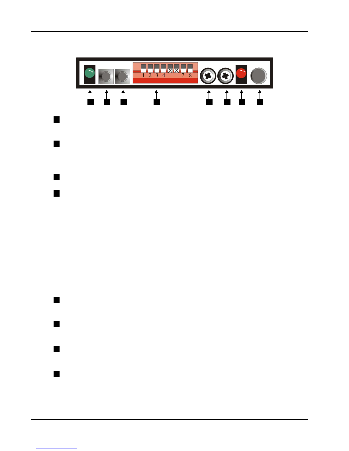
2.2 Mixer Front Panel Access Window
1 2 543 6 7 8
1
Status LED (Green): if lit, AMIX is operating in linked mode; i.e., at least two mixers
are connected together and their switches are correctly configured.
2
Reset Button: restarts AMIX software without powering-down the whole mixer.
Resetting causes the clip (red) LEDs to display a pattern which indicates software version number (see section 3.8).
3
Select Button: used to exclude individual channels from automix.
4
DIP Switches 1-8
Switch 1: selects link mode control configuration (up = master, down = slave)
Switch 2: selects “last mic on” function (up = last mic on)
Switch 3: selects “first-come, first-serve” function (up = first come, first serve)
Switch 4: selects mixer link mode (up = unlink, down = link)
Switch 5: selects escape mode (up=escape mode, down = no escape mode)
Switches 6,7: unused
Switch 8: controls reset mode--up toggles reset to factory defaults (full on),
down toggles preset on reset (preset determined by RS232 command Preset on
Reset). If no preset is defined, then reset uses preset 0 (live crosspoints). Recommended for users of RS232 control. Full on reset is limited by front panel controls.
5
Hold Time Potentiometer: controls the amount of time (ranging from 13 milliseconds
to 1.7 sec.) that an open mic will stay on after there is no direct sound input to it.
6
Off-Attenuation Potentiometer: controls the amount (from 0 to ∞ dB) by which the
level of an open mic is reduced when it is not gated on.
7
AMIX Enable/Disable LED (Red): indicates AMIX module’s functional state. Lit when
AMIX is enabled.
Enable/Disable Button: push (“in” position) to enable AMIX functions. Push (“out”
8
position) to disable.
10
intelix
Page 11

AMIX Series Automatic Mic/Line Mixer User Manual
2.3 Mixer Rear Panel (AMIX-8 shown)
4
123
1
Ground Lift Jumper: jumper J4; connects chassis to electronic ground.
2
AC Power Jack: power supply input; accepts a 4-pin DIN connection from an 18VCT
5
7
6
8 9
10
11
1.5 Amp transformer.
3
Phantom Power Switch: when activated, supplies +15V DC power (for condenser
microphones) to all channels with the mic/line switch set to mic position.
4
Master XLR Output Jack: balanced male XLR jack for master bus output.
5
Master Mic/Line Switch: selects master output to either mic level (-50 dBu) or line level
(0 dBu).
6
DB25 Control Pin Connector: connection points for DC remote control and insert
patching and linking.
7
AMIX-LINK Connector: location for installing AMIX-LINK.
8
RCA input jacks: stereo line level input connections for channel 8 (8001 models) or
channel 4 (4001 models).
9
Channel Input Gain/Trim Control Potentiometer: adjusts gain of input stage over a
range of 40 dBu.
10
XLR input Jack: balanced male XLR input connection, one per channel.
11
Input Mic/Line Switch: selects mic level (-50 dBu) or line level (0 dBu) for correspond-
ing channel.
intelix
11
Page 12

AMIX Series Automatic Mic/Line Mixer User Manual
3.0 AMIX Functions
In addition to standard mixing functions, AMIX also provides standard automatic mixer
functions.
3.1 Threshold Sensitive Gating
Each AMIX mic/line channel will gate on and off when a signal is present. The threshold level
at which the gate-on occurs is set by the channel’s trim control. Properly adjusting the threshold level of each channel ensures an acoustic source will not gate-on multiple AMIX channels.
3.2 Number of Open Microphones Attenuator (NOM)
This function attenuates the master output circuit by 3 dB when the number of channels gated
on doubles. This is an automatic function and compensates for reduced gain before feedback
when multiple channels are open.
3.3 Hold Time Potentiometer
This pot (RP1) controls the amount of time ( from 13 milliseconds to 1.7 seconds) that an
open mic will stay on without direct sound input. This time keeps the open mic from cutting
off sharply when a source pauses between phrases or otherwise rests briefly. The factory
setting is one second; i.e., the left-most half of the LEDs on the temporary bargraph are lit.
Note: When either the hold time pot or the off-attenuation pot are turned, the red clip LEDs
become a temporary bargraph, indicating the setting of the pot.
If the amount of hold time is set too short, the mic turning on and off may cut out parts of
what is being said. Set up the hold time using one channel. Watch the “clip” LED associated
with that channel to see how much time elapses between the end of sound input and the LED
going off (when the LED is lit, the mic is on.)
3.4 Off-Attenuation Amount Potentiometer
This pot (RP2) controls the level to which the signal of an open mic is reduced when it is not
active (not gated on). Reducing the signal rather than turning the mic off completely makes
the gating off and on less obvious, resulting in a smoother sound. The amount of reduction
12
intelix
Page 13

AMIX Series Automatic Mic/Line Mixer User Manual
available using the pot ranges from 0 to ∞ dB. The factory setting is ∞ dB; i.e., all temporary bargraph LEDs are lit. Press reset to check the current setting.
Note: If the off attenuation level is set too high, the amount of gain possible before feedback
will be reduced. When Last Mic On is active, there will always be an open mic, and therefore
some background noise will always be present. In this case, it may be useful to increase the
Off-Attenuation amount (set it near ∞ dB) to reduce the level of the background noise from
“off” inputs.
3.5 User Selectable Modes of Operation
Modes are selectable via the front panel DIP switches (see section 2.2 for dip switch settings).
In linked mode the master unit controls these functions for the entire linked chain.
3.5.1 Last mic on
The last channel to gate-on remains open until another channel is activated. This function is
critical in an environment which requires continual background sound; e.g., broadcast feed or
recording. DIP switch 2 activates this mode in the “up” position and it initiates with the
highest number channel on.
3.5.2 First come, first served
Only one channel may be active at a time. All channels exhibit equal priority. When a channel
is active, all others are inactive until the active channel drops below threshold and is gated off.
This function is useful in environments where only one source should be active at a time; e.g.,
boardrooms, teleconferences, or courtrooms. DIP switch 3 activates this mode in the “up”
position.
This function is affected by the Hold Time Pot. When first come, first served is active, the
active channel will continue as long as there is no lengthy pause allowing another channel to
become active (indicated by the front panel LEDs). If the Hold Time Pot is set at the shorter
end of its range (13 milliseconds), then any pause in the active channel’s input (such as the
talker taking a breath) will cause the channel to shut off. For first come, first served control
to be effective, the Hold Time Pot should be set near the longer end of its range (1 to 1.7
seconds); i.e., the majority of the LEDs should be lit on the temporary bargraph.
3.6 Priority Override
Channel 8 (on AMIX-8) or channel 4 (on AMIX-4) becomes active while all other channels
are muted. This mode is activated by an external switch connected to the DC control connector on the rear of the mixer. This function is used when chairperson priority is necessary.
This AMIX function allows an external (user wired) switch to override the automatic mixing
function by forcing Channel 8 to be on and all the other channels to be off. In stand-alone
mode, the switch is wired to the mixer that the talker is using. When mixers are linked, the
switch must be wired to the master mixer to be effective. The following diagram shows the
wiring of the switch.
intelix
13
Page 14

AMIX Series Automatic Mic/Line Mixer User Manual
Note: when a AMIX-LINK is installed, the
pins used for priority override are pins
“rmtswitch” and ground on the Control pin
port.
Note: The DB25 to which the switch is wired
is the lower one; i.e., the DB25 used for DC
control connections.
3.7 AMIX Channel Exclusion
An individual channel may be deselected from automixing. When deselected, a channel no
longer has threshhold sensitive gating, and is simply open. The channel is no longer part of the
NOM equation. All other user selectable modes of operation will not affect the deselected
channel. This function is used in any case where automixing is undesirable; e.g., background
music source or distant mic source.
To select channels for automix from the front panel, follow these steps:
1) Press the “select” switch. All clip LEDs will be lit (except for channels that
have been excluded from automix). Channel 1’s LED will blink periodically
(AMIX-8 only).
2) Press the “select” button repeatedly until the clip LED for the desired channel is
blinking.
3) Hold the select button for 2 seconds or more to toggle the setting of automix
include/exclude. When the LED is on that channel is included, and will be
automixed. If the LED is off, that channel will be excluded from automix.
VCX Control Connector
R
L
Aux and Control
This process is also available through RS232 commands.
3.8 AMIX Software Version
AMIX Software version is indicated by patterns in
the LEDs on the front panel of the unit during power
up or during reset.
14
intelix
Page 15

AMIX Series Automatic Mic/Line Mixer User Manual
4.0 Installation of the AMIX Mixer
4.1 Unpack, Connect, and Power-up
A. Take the mixer out of its box and inspect for shipping damage. If there is obvious physical
damage contact Intelix before proceeding.
B. Turn all mixer Volume Control Knobs (individual channels and master) to zero.
Turn external amplifier volume controls to zero.
4.2 Connect Inputs
For each input channel (up to 4 for AMIX-4; up to 8 for AMIX-8), insert the XLR input
connector into the desired XLR Input Jack on the rear panel.
Press the XLR Input Pad Microphone/Line Switch to appropriate position: “in” for line input
or “out” for mic input. Note that the input from some microphones is actually close to line
level (-20 dB) and for such mics, the Switch should be at “line”.
Note: Set all unused channels to line level.
4.3 Channel 4 (on AMIX-4) or 8 (on AMIX-8)
This channel accepts two types of inputs. Two inputs may be connected to the channel at the
same time, but only one at a time may be mixed.
The position of the channel’s XLR Input Pad Microphone/Line Switch determines which
input is mixed into the output: in the “mic” position, it uses the input connected to the XLR
Input Jack; in the “line” position, it uses the input connected to the RCA Jacks.
intelix
15
Page 16

AMIX Series Automatic Mic/Line Mixer User Manual
Note: This channel accepts stereo inputs via the RCA
jacks. The channel’s output to the mixer is the mono sum
of the “R” and “L” RCA jack inputs.
The XLR jack for this channel accepts only mic level
inputs.
4.4 Connect Output
A connection should be made between the Master Output XLR Jack and an input jack of the
amplifier or other downstream equipment.
Press Output Pad Microphone/Line Switch to appropriate position: “in” for line-level output
(0 dBu) or “out” for mic-level (-50 dBu) output.
4.5 Power Up
4.5.1 Connect the mixer power supply
Connect the mixer’s power supply to an AC power
outlet and then to the AC Power Jack on the far left
side of the rear panel.
4.5.2 Power up the mixer
1) Press the Power Switch to the “in” position (the
power indicator LED will light if mixer is powered).
2) Set the Master Output Volume Knob to “7”.
3) Power up the external amplifier.
16
intelix
Page 17

AMIX Series Automatic Mic/Line Mixer User Manual
5.0 Gain Structure
To obtain the best performance from your Intelix AMIX mic/line mixer, you should first
understand the basic gain structure of the unit. There are four stages of gain adjustment
(labelled #1 through #4 in the drawing below):
1) channel input gain/trim control: this rear panel potentiometer controls the gain of the
microphone preamplifier.
2) channel volume knob: this front panel potentiometer controls (through the channel VCA)
the amount of channel that is fed to the mixer’s summing bus.
3) master volume control: this front panel potentiometer controls (through the master VCA)
the amplification of the summing bus to the output connector.
4) external amplifier volume control (not part of the mixer): sets the final listening level of
the loudspeakers.
The goal of setting up the mixer’s gain structure is to adjust these four controls for the desired
volume, while maintaining the best possible signal-to-noise ratio (S/N) through the mixer. This
is done by setting controls 2 and 3 at “7” where S/N and headroom are optimized, using
controls 1 and 4 to achieve maximum gain before distortion. Gain structure must be set with
all AMIX functions disabled.
In order to maintain the highest level of S/N in the mixer, the audio signals are never brought
through the front panel controls of the Intelix mixer. Instead, each front panel pot controls a
Voltage Controlled Attenuator (VCA), which controls the associated amplification stage. The
channel VCAs do not control an amplifier, but are attenuation only devices which determine
the amount of each channel’s contribution to the summing bus.
intelix
17
Page 18

AMIX Series Automatic Mic/Line Mixer User Manual
5.1 Setting the AMIX Mixer Channels
Preliminary steps:
1) Connect audio sources to channel inputs
2) Connect the mixer output to an external amplifier
3) Set input mic/line switches for each channel and the output
4) Turn on phantom power switch (if condenser microphones are in use)
5) Turn the master volume control to “0”
For each channel follow these steps:
1) Set the channel volume control to “0”
2) While driving the channel input at its normal level,
adjust the rear panel input gain/trim control clockwise
until the peak (red) LED for the channel is illuminated.
Then turn the input gain/trim control counterclockwise
until the red LED goes out. Note that the signal present
(green) LED will stay lit during this procedure.
3) Turn the master output volume knob to “7”.
4) Adjust external amplifier volume to the desired
acoustic level.
5) Adjust individual channel volume knobs to the
desired levels, as indicated on the bar graph (the bar
graph monitors the output, but if one channel is adjusted at a time, the graph will
reflect only that channel).
Red
Green
18
intelix
Page 19

AMIX Series Automatic Mic/Line Mixer User Manual
6.0 Mixer Fine Tuning
6.1 Low Cut Switch
To remove excessive bass response from an
individual channel, press that channel’s low
cut switch.
The low cut feature helps eliminate low
frequency noise (signals of 150 Hz or lower;
e.g., ventilation rumble). This feature is
primarily used with mic-level inputs and is
particularly effective with hand-held microphones.
6.2 Phantom Power Switch
If a condenser microphone is not independently powered,
press the phantom power switch to the on position. This
will cause the mixer to power condenser mics through
the mic cable. When the phantom power switch is in the
on position, all channels whose mic/line switches are in
the mic position receive phantom power (+15 VDC).
6.3 Aphex® Aural Exciter®
This feature enhances signal intelligibility by adding supplementary
harmonic information. It is especially effective at clarifying speech.
To engage the Aural Exciter®, press the Aphex Exciter switch to
the on position.
6.4 Output Limit Switch
The Output Limiter is a safety feature which protects the entire audio system from excessive
volume levels. It ensures the signal leaving the mixer does not exceed the system’s safe dynamic range. The factory setting is 0 dBu, but the threshold is variable from -20 dBu to +20
dBu and is set by adjusting a potentiometer inside the mixer chassis (see sec. 8.3 for location
of Output Limiter Threshold Potentiometer).
If during ordinary use one or more inputs occasionally exceed the maximum input levels set
up during the set up procedure (sec. 5.0) (i.e., the red (+12 dB) LED on the bar graph meter
occasionally lights), press the Output Limiter Switch to the on position.
intelix
19
Page 20

AMIX Series Automatic Mic/Line Mixer User Manual
If during ordinary use one or more inputs continually exceed the maximum level (i.e., the red
LED continually lights), the input volume must be reset; return to the set up procedure as
defined in Section 5.
Note: If the amplifier/speaker combination is such that the speakers can be overdriven to
failure, always operate the mixer with the Output Limit Switch in the on position.
6.5 Select Bar Graph Readout
The LED Bar Graph Output Meter may be set to register either the peak or average level
of the output audio signal. To do so requires opening the chassis. The locations of the jumpers
for this are shown in section 8.3. The factory setting is to the average level; i.e., the Average
Bar Graph Jumper (J 3) is in place. To select peak level, move the jumper from J3 to the
Peak Bar Graph Jumper (J 2) instead. For the meter to operate, a jumper must be in one of
these two positions. Never place jumpers in both positions.
6.6 The Ground Lift Jumper
The ground lift jumper on all AMIX series mixers is a feature designed to help prevent ground
loops. When jumper J4 is present, it grounds the mixer to its chassis. If the mixer is installed
in a non-metal cabinet, the jumper is left in place. When the mixer is installed in a grounded
metal rack frame, use a needle-nose pliers to remove the jumper via the ground lift jumper
access (see Section 2.3).
6.7 Rack the Mixer
Install the mixer in the rack or other cabinet where it will be when in use. The mixer should
be located away from heat sources, including other electronic components which generate a
large amount of heat, such as amplifiers. Verify the unit is well-secured.
20
intelix
Page 21

AMIX Series Automatic Mic/Line Mixer User Manual
7.0 Setting AMIX Functions
Before proceeding to the adjustment of AMIX functions, ensure the following steps have been
completed:
1) Turn all volume knobs on both the mixer and the amplifier to zero.
2) Connect inputs and set all mic/line switches to their appropriate levels (all unused
channels should be set to “line”.
3) Connect the output and set the mic/line switch appropriately.
4) Turn on the low cut switches for all active channels.
5) Connect the mixer power supply and plug into an AC outlet.
6) Power up the mixer and the amplifier.
Now proceed to the following steps:
A.Power the AMIX module by pushing button 8 on the right-hand side of the
AMIX module to the “in” position. Activating the AMIX functions will cause the
level of background noise transmitted by the mixer to change. This is because the
AMIX module is automatically controlling the output level of the mixed signal.
B.Adjust the input volume for each channel. Note: Channel isolation is an iterative
process, it may be necessary to go through checking all the mics more than once inorder to have each channel completely isolated.
Set Signal Present Level:
1) Turn all volume levels to zero.
2) Place microphones in the positions they will occupy during the event.
3) For each channel, speak in a normal tone into the mic being adjusted. Use a
small screwdriver to turn the rear panel input gain/trim control clockwise
until the red Signal Clip LED is steady on. The LED acts as channel on indicator.
4) Turn on the amplifier and set the mixer’s master volume to 6 or 7. Adjust
the front panel volume control knob for each channel to the desired level
(rather than using the clip LED as a guide because of its dual function as a
signal detect LED).
intelix
21
Page 22

AMIX Series Automatic Mic/Line Mixer User Manual
C.Select special modes and functions by setting DIP switches 1-4:
Switch 1: selects link mode control configuration (up = master, down = slave).
Switch 2: selects “last mic on” function (up = last mic on).
Switch 3: selects “first-come, first-serve” function (up = first come, first serve).
Switch 4: selects automatic mixing linking mode (up = unlink, down = link).
For stand-alone operation, whenever a mixer is physically linked, Switch 4 must be
set in the “up” (stand-alone) position.
7.1 Channel Isolation
With the volume control knobs at the positions which give the desired volume for each channel, verify that each mic is “isolated”. To do this, return to mic 1 and make sure that speaking
into it causes no other mic to come on; i.e., the Signal Clip LED (Red) for that only that
channel is lit. If other mics come on, then re-adjust the gain for those channels (decrease gain
by adjusting the rear panel pot). Repeat for each individual mic.
Note: When changing the mixer from stand-alone to linked operation or vice versa, the
channel isolation procedure may have to be performed again.
7.2 Fine Tuning AMIX Functions
AMIX mixers operating in the automatic-mix mode have several features which require
additional adjustment in order to optimize the mixed sound. Because the signals are mixed
automatically, any adjustment to the gain of one channel will influence all the others; making
such a change may necessitate making changes to the settings of other channels.
There are two potentiometers (pots) on the front panel (see Section 2.2) that may need adjustment, especially when linking or unlinking mixers, or changing the status of functions such as
Last Mic On.
The relative values at which the pots are set can easily be gauged during adjustment using the
red (clip) channel LEDs. The LEDs act as a temporary bargraph for the two pots: when the
pots are full-on, the LEDs are all lit (AMIX-4 has four LEDs and AMIX-8 has eight LEDs).
When the pots are full-off, none of the LEDs are lit. This bargraph function begins when the
pots are rotated and lasts for a few seconds after the adjustment stops.
Adjust these pots by powering the AMIX module and using only one mic. Observe the behavior of the red LED associated with that mic and adjust the pots to the desired response levels.
In linked mode, the master unit controls both these functions for all the units in the chain; i.e.,
only the pots on the master units are active; all others are disabled.
22
intelix
Page 23

AMIX Series Automatic Mic/Line Mixer User Manual
8.0 External Control
Intelix AMIX series mixers have several special built-in features which make the remote
control and muting of both the individual channel inputs and the master output easy to activate and simple to change. The ability to enable external audio signal modifications, such as
insert patching and direct outs, is also built-in. The activation of all built-in features requires
wiring of external devices (potentiometers, switches, etc.) to a male DB25 connector.
8.1 The Connectors
All external controls and signal sources are attached via the DB25 Control Pin Connector.
Note that AMIX-4 has external control over all channels, while the AMIX-8 has external
control only over even numbered channels.
The female DB25 pinout for AMIX-4
mixers. The view is of the rear panel.
Header P12 is inside
the mixer chassis and
contains jumpers that
must be correctly set
for external control.
intelix
The female DB25 pinout for AMIX-8
mixers. The view is of the rear panel.
23
Page 24

AMIX Series Automatic Mic/Line Mixer User Manual
8.2 DC Control
AMIX Series mixers are configurable for external control of individual channel volume by a
DC voltage. Up to 4 input channels and the master output volume can be connected to remote
controls simultaneously.
Note: The following instructions assume that the remote control device is a 10KΩ potenti-
ometer. If another device is used, these instructions may require modification.
8.2.1 Remote volume control
When a remote control device (typically a linear 10kΩ pot) is installed, it controls the percent-
age of the volume possible as defined by the Volume Control Knob on the front panel for that
channel. For example, if the Volume Control Knob is set at 8, and the remote pot is set at 5,
the result will be 4 (50% of 8). Only when the Volume Control Knob is set at 10 does the
remote device have full control over the channel’s input level.
8.2.2 Connecting a remote volume control
The following instructions show how to connect a linear 10kΩ pot to a single channel as a
remote volume control. Repeat this process for each channel to be remotely controlled.
1) Remove the channel’s jumper from header P12 (see
Section 8.3 for locations).
2) Connect a wire between one end of the potentiometer and the channel’s high pin on the DB25 connector.
3) Connect a wire between the other end of the potentiometer and a ground pin on the DB25 connector.
4) Connect a wire from the wiper of the potentiometer
and the channel’s wiper pin on the DB25 connector.
8.2.3 Remote mute control
All channels whose high and wiper pins are brought out to the DB25 connector can be remotely muted.
This is done by connecting a switch (or other dry contact closure) between the channel’s
wiper pin and ground. Shown are two ways to wire a channel for external muting. Note that
remote mute control can be used alone or in combination with remote volume control.
8.2.3.1Wiring an external mute switch
The following instructions show how to connect a single channel for remote muting. Repeat
this process for each channel to be remotely muted.
24
intelix
Page 25

AMIX Series Automatic Mic/Line Mixer User Manual
1) Connect a wire from the high pin of the channel to be muted.
2) Connect the other end of that wire to the wiper pin of the
channel to be muted.
3) Connect a wire from one side of the switch to the wiper pin of
the channel to be muted, the same pin as step 2.
4) Connect a wire from the other side of the switch to a ground
pin on the DB25 connector.
8.2.3.2 Wiring an external combination mute switch and volume control
The following instructions show how to connect a linear 10kΩ pot to a single channel for
remote muting and a remote mute switch. Repeat this process for each channel to be remotely
controlled.
1) Remove the channel’s jumper from P12.
2) Connect a wire from one side of the switch to the
wiper pin of the channel to be muted.
3) Connect a wire from the other side of the switch to a
ground pin on the DB25 connector.
4) Connect a wire from one end of the pot to the
channel’s high pin.
5) Connect a wire from the other end of the pot to a
ground on the DB25 connector.
6) Connect a wire from the wiper of the pot to the
channel’s wiper pin on the DB25 connector.
8.3 Circuit Board Map
The following drawing shows the location of several components on the AMIX circuit board
which are user accessible to fine tune some AMIX functions. The components include potentiometers RP13 and RP14, as well as the ground lift jumper J4 and the Premaster Insert Patch
Jumper J1. Some components in this picture may be hidden from sight by the AMIX board.
intelix
25
Page 26

AMIX Series Automatic Mic/Line Mixer User Manual
8.4 Master Output Insert Patching
If no AMIX-LINK is being used on the AMIX mixer, you can do master output insert patching. To use the patching feature of the AMIX mixer follow these directions:
1) Remove the top of the mixer chassis, and remove jumper J1.
2) Connect a wire from pin 12 of the DB25 connector to the input of the destination
device.
3) Connect a wire from the output of the
destination device to pin 13 of the DB25
connector.
This drawing illustrates the function of the patching feature of the AMIX mixer. The summed bus
output is sent to an external device on pin 12 of
the mixer’s DB25. The external device’s output is
sent back to the mixer on pin 13 of the mixer’s
DB25. Note that jumper J1 is removed for insert
applications.
Note: If a patched application is no longer desired, jumper J1 must be replaced.
26
intelix
Page 27
AMIX Series Automatic Mic/Line Mixer User Manual
9.0 Passive Mixer Linking
Mixer linking allows the user to add additional microphone or line level inputs as needed
without the loss of inputs or automatic features.
There are two methods of linking AMIX mixers, passive or active linking. Passive linking uses
only cables, whereas active linking uses the Intelix AMIX-LINK. Passive linking is suitable for
linking two mixers, whereas active linking is easier and more flexible. Using the AMIX-LINK,
up to six AMIX mixers can be linked into a single stack. In any stack, one mixer is the master
and all the others are slaves.
Linking involves three steps:
1) Set the DIP switches
2) Connect the control chain
3) Connect the audio chain
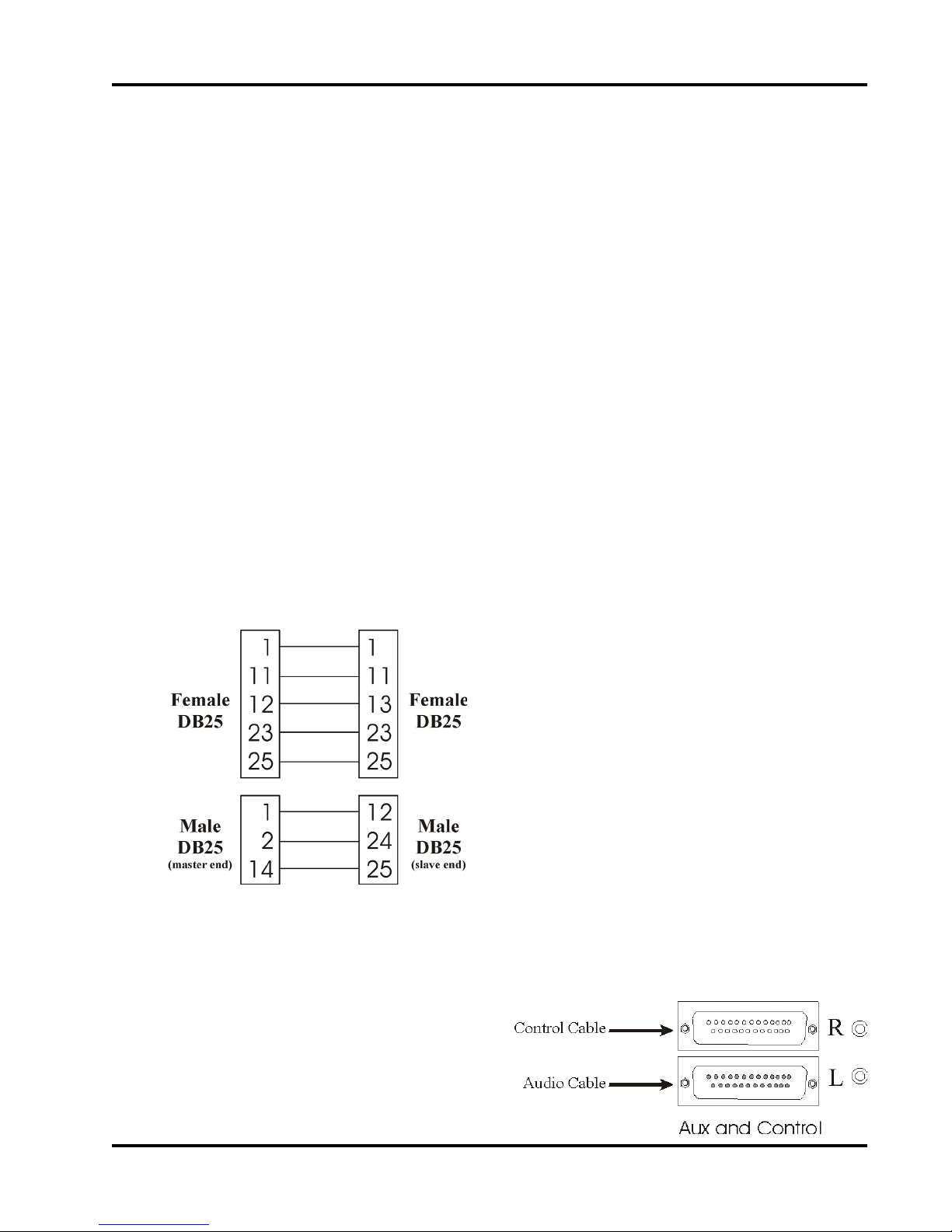
9.1 Making the Cables
Two cables must be made to link two mixers: the control cable (female DB25 to female
DB25) and the audio cable (Male DB25 to Male DB25). Note: The audio cable is not sym-
metrical; i.e., the pin configurations at each end of the cable are different.
9.2 Connecting the Cables
After the cables are made and tested for correct wiring, connect the control and audio chains
as shown. The two control ports (the upper
DB25) are connected together. The two
audio ports (the lower DB25) are connected together, keeping in mind that the
audio cable has a master end and a control
end.
The wiring diagram for the control cable. This
cable is symmetrical; i.e., either end can be
connected to the master. No pins other than the
ones shown should be connected.
The wiring diagram for the audio chain cable. This
cable is not symmetrical; i.e., the ends must be
connected as marked. Label the ends of this
cable! No pins other than the ones shown should
be connected.
intelix
27
Page 28

AMIX Series Automatic Mic/Line Mixer User Manual
10.0 AMIX-LINK Module
This section describes the capabilities, operation and use of the AMIX-LINK Module. The
Link Module is an accessory to the Intelix AMIX-4 and AMIX-8.
The Link Module attaches to the rear of the AMIX mixer chassis, dramatically extending the
capability of the AMIX mixer. Two labeled views of the Link Module are shown below. The
principle function of the Link Module is to:
♦ Provide a simple method of linking multiple AMIX mixers.
♦ Provide ports for external equipment audio patching capability.
♦ Provide a port allowing remote control of the AMIX mixer.
♦ Provide a port for full remote control via an external mini-mixer controller.
♦ Provide signal present indicators (one for each channel) used to control any
desired remote function.
♦Provide an RS232 computer control port to provide for computer control.
28
intelix
Page 29

AMIX Series Automatic Mic/Line Mixer User Manual
10.1 Quick Start for AMIX-LINK
This section gives instructions for setting up and linking two AMIX mixers using AMIXLINK Modules.
10.1.1 Installing theAMIX-LINK
Plug the two male DB25 connectors on the AMIX-LINK firmly into the two female DB25
connectors on the back of the AMIX mixers. Tighten the four capture screws on each AMIXLINK to secure the modules to the mixers. If you wish to use the insert/patch capacity of the
AMIX mixer stack, please refer to section 10.2.2.
10.1.2 Setting the DIP switches
Decide which mixer will be the master, keeping in mind the master should be ergonomically
convenient. The other mixer becomes the slave.
On the mixer you have designated as the master, set DIP switch 1 (on the far left) to the “up”
position. This designates the mixer as a master. Set DIP switch 4 to the “down” position. This
puts the mixer in linked mode.
On the slave mixer, set DIP switch 1 (on the left) to the “down” position. This designates
the mixer as a slave. Set DIP switch 4 to the “down” position. This puts the mixer in linked
mode.
10.1.3 Connecting the control chain
Using one of the included control cables (they have a RJ11 or phone type plug on both ends),
connect the master mixer’s M-out/S-in port to the slave’s M-out/S-in port.
Using the other control cable, connect the slave’s M-in/S-out port to the master’s M-in/S-out
port.
10.1.4 Connecting the audio chain
Using the included audio cables (they have an RCA phono plug on both ends), connect the
slaves “Link Out” port to the master’s “Link In” port.
Note: There should be no connection to the master’s “Link Out” ports. The only connection
to the slave’s “Link In” port should be the supplied shorting plug.
intelix
29
Page 30

AMIX Series Automatic Mic/Line Mixer User Manual
AMIX Mixer (Slave)
Fig. 7. This drawing
shows the connections
and switch settings
Mosi
LI
Miso
LO
Ins
required for the correct operation of a two
mixer stack. The
supplied grounding
plug should be left in
place in the Link In
Mosi
Port of the slave mixer
as shown (the black
Miso
LOLIIns
disk).
10.2 Installation of the AMIX-LINK
10.2.1 Installing
The AMIX-LINK’s two DB25 connectors plug directly into the two DB25 connectors on the
back of the AMIX. Secure the two AMIX-LINK connectors to the two AMIX connectors
with the four captured screws of the AMIX-LINK’s two DB25 connectors.
AMIX
AMIXLINK
AMIX
AMIXLINK
SW1
SW4
AMIX Mixer (Master)
10.2.2 Removing Jumper J1
If you ever intend to use the insert/patch functions of the AMIX-LINK, the Jumper J1 must be
removed from the mixer circuit board. This jumper is located as shown below. This drawing
shows the mixer board, with the top of the chassis and the AMIX-LINK Module removed.
The jumper J1 cannot be removed with the link module in place. After the AMIX-LINK
Module is removed, locate, remove, and discard jumper J1, then reinstall the link module.
If you never intend to use the insert/patch functions of the AMIX mixer, leave J1 installed (as
it comes from the factory).
The position of J1 on the AMIX mixer board. The drawing is looking down on the mixer from
behind. Remove J1 by pulling straight up. The jumper may be discarded after removal.
30
intelix
Page 31

AMIX Series Automatic Mic/Line Mixer User Manual
10.3 AMIX-LINK Connector Descriptions
This section provides a description of each port on the AMIX-LINK with a reference to the
manual section explaining how to use that port.
10.3.1 Gate logic output port description
The Gate Logic Output port provides a digital output signal (active high) for each channel.
This port provides “state” information which can be translated by a remote device into an
action; e.g., remote camera that points at the
current speaker. When a channel is gated on, its
corresponding Gate Logic Output pin is driven
high.
Pin assignment of the Gate
Logic Output port viewed from
the back of the AMIX-LINK.
10.3.2 M-out/S-in and M-in/S-out port description
The M-out/S-in (Mosi) and M-in/S-out (Miso) RJ12 connection ports are used in linking
multiple AMIX mixers. Mosi and Miso carry control signals around the control loop of the
linked mixers.
10.3.3 Insert, Link In, and Link Out port description
The Link In and Link Out ports are used to carry the audio signals among the linked mixers.
For each mixer in the stack, the Link In port is connected to the Link Out port of the previous
mixer in the stack.
As a secondary function, the Link In and Link Out ports are used for the external equipment
audio patching function. In this case, the Link Out port is used as an audio patch out port. It is
used in conjunction with the Insert port to provide an input and output for the patching
function.
The right side of the AMIX-LINK,
showing the Link In, Link Out, and
Insert ports.
10.3.4 The ReO port description
The ReO port allows the user to connect an Intelix mini-mixer controller to the AMIX. The
mini-mixer is a small, portable controller. This device permits all AMIX channel levels, including the master, to be adjusted from a remote location.
Link In Link Out Insert
intelix
31
Page 32

AMIX Series Automatic Mic/Line Mixer User Manual
10.3.5 The RS232 port description
The RS232 port is used to connect an external programmer to the AMIX mixer. Usually this
is a laptop PC.
10.3.6 Control pin port description
The Control Pin Port provides direct connections to the manual control functions on the
AMIX main circuit board. Controls attached to this port control master volume, as well as
individual channel volumes and muting for channels 2, 4, 6, and 8 on eight channel mixers,
and channels 1, 2, 3, and 4 on four channel mixers. The pin assignment of the Control Pin Port
is shown below.
Control Pin Port pin assignment
r
m
t
s
w
i
t
c
h
2
g
n
d
g
n
H
d
i
g
h
4
2
H
W
i
i
g
p
h
e
r
4
g
n
W
d
i
p
e
r
g
6
H
i
g
h
6
n
d
W
i
p
e
r
10.4 Connecting AMIX-LINK Ports
This section explains how to wire and use each port on the AMIX-LINK.
10.4.1 Connecting to the Gate Logic Output port
To make connections to the Gate Logic Output port, use a jeweler’s screwdriver to loosen the
top screw corresponding to the desired channel, insert a stripped 18-22 gauge signal wire into
the back of the connector pin, and retighten the screw. Repeat for each channel to be connected. The wire from the channel becomes
active (high) when that channel is gated on. This
+5V TTL signal may be used for any signaling or
control function (i.e., LEDs, 5 Volt logic, and
relays).
m
g
m
8
H
i
g
h
8
g
n
d
n
d
W
i
p
e
r
g
s
n
t
d
r
H
i
g
h
g
s
t
r
W
p
r
g
n
n
d
d
32 intelix
The Gate Logic Output port
pinout
Page 33

AMIX Series Automatic Mic/Line Mixer User Manual
AMIX-LINK
External Circuits
+5V
p10
470Ω
p9
LEDs
1-8
470Ω
p2
p1
Example of the Gate Logic Output port
used to control LEDs.
AMIX-LINK
External
+5V
Circuits
p10
470Ω
p9
+5V
logic
gates
1-8
470Ω
p2
p1
Example of using the Gate Logic Output
Port to drive 5V logic circuits. Note that
the logic outputs of the Gate Logic Output
Port are active high.
AMIX-LINK
+5V
470Ω
p10
p9
External
Circuits
Relays 1-8
Relay 1
Relay Drive
10mA maxi-
An example of using the
control port to control a
relay circuit.
mum per
channel
470Ω
p2
p1
10.4.2 Connecting to the ReO port
When remote control of all channels levels is required, the ReO port can be used to connect
an Intelix mini-mixer to the AMIX mixer. This is accomplished by inserting an RCRJ11 adaptor into the ReO port of the AMIX-LINK. Then the cable provided with the mini-mixer can be
connected between the adapter and the mini-mixer. The AMIX mixer levels are now fully
controllable from the remote mini-mixer. A stack of mixers cannot be controlled with a single
mini-mixer; i.e., there must be one mini-mixer per mixer chassis.
33intelix
Page 34

AMIX Series Automatic Mic/Line Mixer User Manual
AMIX ReO port adaptor
Typical connection of a
mini-mixer to the AMIX
mixer, using the PRJ12/
DB9-F adaptor
wiring diagram
10.4.3 Connecting to the RS232 port
The RS232 port is used to connect an RS232 controller to the AMIX. This is done by connecting the controller’s output to the
AMIX-LINK’s RS232 RJ12 port.
The adaptor from the controller’s
DB9 connector to the AMIX-LINK’s
RJ12 connector is made through the
AMIX RS232 adaptor available from
Intelix.
AMIX RS232 port adaptor wiring diagram.
Typical connection of a laptop
PC to the AMIX mixer, using
the Intelix RS232 adaptor and a
null modem cable.
34 intelix
Page 35

AMIX Series Automatic Mic/Line Mixer User Manual
10.4.4 Connecting to the control pin port
With proper connections to the Control Pin Port, the user can remotely control volume and
muting of the following channels: 2, 4, 6, 8, and the master output. If it is necessary to have
individual remote control over all channels, an Intelix mini-mixer connected through the ReO
port should be used.
When a remote volume control is attached to a channel, it sets the proportion of the volume
control setting on the mixer front panel. For example if the Volume Control Knob is set to 7
and the remote control is set at 3, the output volume is 30% of 7, or 2.1. The maximum
possible volume in this example is 7, obtained when the remote control is at 10. Only if the
mixer’s volume control knob is set at 10 does the remote control have full control over the
channel’s volume.
Connecting a remote control devices to the AMIX-LINK Control Pin Port requires two steps:
♦ Wiring external devices to the Control Pin Port pins
♦ Setting internal jumpers
Note:Wiring for the Priority Override Feature.
For a full explanation of the priority override feature, please see section 3.6. When using
priority override with a Link Module, connect the remote switch across pins 1 and 2
(“rmtswitch” and “gnd”) of the Link Module’s Control Pin Port.
10.4.5 Wiring external devices to the control pin port
The following three figures explain how to make the connections to the pins of the Control
Pin Port to implement the remote volume and muting control functions. The connector consists of twenty screw type connections. Connection to a pin is made by loosening the screw on
top of the connector with a jeweler’s screwdriver, inserting a stripped wire into the pins
opening at the side of the connector, and retightening the screw. The connectors are most
easily wired with 18 - 24 gauge wire, and each pin will accept two of any of these wire sizes.
Wiring diagram for a remote volume control. Connect one end of
a 10-KΩ potentiometer (pot) to the High pin of the channel to be
controlled. Connect the other end of the pot to the adjacent
ground pin, connect the pot’s wiper connection to the channel’s
wiper pin. All ground pins are equivalent and can be used interchangeably. The remote control is now connected. Note: if the
selected channel is the Master channel (i. e., the pot uses pins
“mstr High” and “Mstr Wiper”, then the remote pot will
control the master volume from the mixer).
35intelix
Page 36

AMIX Series Automatic Mic/Line Mixer User Manual
Wiring diagram for a remote mute switch. When the switch is
depressed the channel to which it is connected will be muted until
the switch is released. Connect a jumper wire between the selected
channel’s high pin and wiper pins. Connect one end of the mute
switch to the channel’s wiper pin (the same pin that is jumpered to
the high pin). Connect the other end of the remote mute switch to
the channel’s ground pin. The mute switch for the selected channel
is now wired.
Wiring diagram of combined remote volume control and remote
mute switch. Depressing the switch will mute the selected channel
until the switch is released. Then connect one end of the muting
switch to the channel’s wiper pin (the same pin that already contains
the wiper connection of the volume control pot). Connect the other
end of the mute switch to the channel’s ground pin. The remote
volume control and the remote muting switch are now wired.
10.4.6 Setting internal jumpers for the control pin port
For each channel using a remote volume control, a jumper must be removed from the AMIX
module circuit board inside the mixer chassis. These jumpers are on connector SK12 on the
AMIX circuit board, as shown below. Remote muting switches require no jumper changes.
10.4.6.1 To set jumpers
Remove the ten screws holding the cover of the AMIX Mixer in place. Locate connector
SK12 as shown below. For each channel using a remote volume control pot, remove the
jumper corresponding to that pin from SK12. See Section 8.3 for jumper assignments. SK12
is the same as P12.
Note: While the cover is off, confirm that all channels without external remote controls
have the corresponding jumper installed.
Channels 1, 3, 5, and
7 should also have
jumpers installed.
Replace the cover on
the mixer, securing
with the ten screws.
36 intelix
Page 37

AMIX Series Automatic Mic/Line Mixer User Manual
u
u
n
n
D
u
U
s
C
e
K
d
D
V
U
O
C
L
K
1
V
u
O
s
L
e
1
d
V
V
O
O
L
L
3
2
The pin assignment of jumper block SK12 on the AMIX module logic board. The AMIX-4
channel pinout is shown above the connector drawing. Note: For the connection of Control
Pin Port control devices, it should never be necessary to move any jumpers except Vol2, Vol4,
Vol6, Vol8, and MSTR.
u
u
n
n
V
u
u
O
s
s
L
e
e
2
d
d
V
O
L
4
V
V
O
O
L
L
7
5
V
V
O
O
L
L
4
3
V
V
O
O
L
L
6
8
M
S
T
R
M
S
T
R
A
L
G
P
I
E
M
X
A
L
P
I
E
M
X
G
N
N
D
D
G
G
N
N
D
D
Pinout for AMIX-4
Pinout for AMIX-8
10.5 Using the Link In and Link Out Ports
There are three principal uses of the Link In and Link Out ports.
♦ Facilitate linking of multiple AMIX mixers
♦ Provide tapping and patching of the audio signal.
♦ Provide an extra mixer input
10.5.1 Tapping and patching with the AMIX-LINK
The AMIX-LINK allows the user to tap (insert) or patch an external device into the mixer
audio output path. In order to use the insert or patch capabilities of the AMIX mixers, you
must remove jumper J1.
Tapping the mixer output routes the mixer output to an external device (such as a recorder),
but does not return the signal to the mixer from the external device. A tapped output’s level is
not controlled by the mixer. The external device determines the final level. A diagram of a
tapped installation follows.
Patching the mixer output routes the output signal to an external device, which does return
the signal to the mixer. A patched output’s level is controlled by the mixer. A diagram of a
patched installation follows.
37intelix
Page 38

AMIX Series Automatic Mic/Line Mixer User Manual
8
Mixer Inputs
Recorder
AMIX Mixer
AMIX Link Module
Link Out port
Recorder input
An example of a tapped installation. The mixer output via the Link Out port is sent to the
recorder, which has final control of the audio level since the signal never returns to the mixer.
Amplifier Input
Amplifier
8
Mixer Inputs
Mixer Output
AMIX Mixer
AMIX Link Module
Link Out port
Insert Port
Equalizer
EQ input
EQ output
An example of a patched installation. The mixer maintains control of the final volume sent to
the amplifier, since the external Equalizer returns the equalized audio to the mixer through the
Insert port.
When a tapped installation is desired, the audio signal is taken from the Link Out port and
routed to the external device.
In a patched installation the audio signal is taken from the Link Out port and routed to the
external device, which sends the modified signal back to the mixer through the Insert port.
Note: When using the patching technique both jumper J1(Section 10.2.2) on the AMIX mixer
circuit board and jumper J5 on the AMIX-LINK must be removed.
10.5.2 Using the Link In port as a balanced line input
If an additional balanced line-level input is needed, the Link In port will serve this function.
This input goes directly to the summing bus and has no input volume control, thus input level
control must be provided by the input device. The Link In Port is an ungrounded differential
input. To correctly wire this input to the AMIX-LINK RCA port, follow the following directions.
38 intelix
Page 39

AMIX Series Automatic Mic/Line Mixer User Manual
10.5.2.1 If your source is balanced
√ Tie the braided shield to ground at the source end, and leave it unconnected at the
AMIX-Link Module end.
√ Tie the positive signal lead to an RCA connector center pin.
√ Tie the negative signal lead to the RCA connector case.
+
Balanced source hookup.
-
Balanced
Source
10.5.2.2 If your source is unbalanced
√ Tie the ground lead to the RCA connector case.
√ Tie the positive signal lead to the RCA connector center pin.
+
Unbalanced
Source
RCA Plug
Unbalanced source hookup.
RCA Plug
39intelix
Page 40

AMIX Series Automatic Mic/Line Mixer User Manual
11.0 Troubleshooting Tips
NO POWER
¾ Check the connections between the mixer and the power supply and the external
AC power supply.
¾ Check the wall outlet.
NO SOUND
¾ Make sure the mic/line switch is in the proper position. (This is the most likely
cause.)
¾ Make sure both the master and channel input controls are turned up.
¾ Check that the source signal cable(s) is properly connected and undamaged.
¾ Adjust trim/gain potentiometer(s) to increase gain.
¾ If there is still no sound, try changing input source(s) to different channel(s).
¾ Make sure that jumper J1 is in place (see page 30).
DISTORTED SOUND
¾ Turn down the master volume control. If distortion persists, input channel(s) is
likely cause.
¾ Check position of all line/mic switches.
Check the position of DIP switch number 8 it should be in the up position unless
you have special reset requirements (see page 13 ).
¾ Determine the distorting input channel(s) by checking them one at a time.
¾ Decrease gain of input channel(s) causing distortion. (By turning the gain/trim
control potentiometer on the rear panel.).
EXCESSIVE HISS or HUM
Hiss: Make sure the volume control knobs for all the unused channels are set at “0”
and in line position. Make sure the mic/line switch is in the correct position for both
the input and output.
Hum: Mics lines can easily cause hum. Make sure to locate them away from vibration
and magnetic field sources (motors, power supplies and lines, and data lines).
Check mic lines, especially the shield, for damage.
Another common source of hum is a ground loop, which can result from connecting
two or more powered devices together. Turn the master volume down. If the hum is
still present, the ground loop or other cause is not in the mixer, but in the connections
or devices after the mixer in the audio path.
If the hum is “in” the mixer, first check to see if the Ground Lift Jumper (J4) is
present. It should be removed, unless the mixer is in a nonmetal cabinet. Check for
unbalanced connections; use balanced connections, if possible. For all unbalanced
connections, try to disconnect the signal line ground to “lift” the ground.
40 intelix
Page 41

AMIX Series Automatic Mic/Line Mixer User Manual
12.0 Technical Specifications and Line Drawings
AMIX-4 Front and Rear
GENERAL
Frequency Response
Max Voltage Gain
Signal to Noise
Equivalent Input Noise
Crosstalk
Channel Gating
Holdtime
Off-Attenuation
Bar Graph
Reading
Attack
Decay
Signal Present Indicators
Input Clip Indicators
Limiter Threshold
Adjustment
Control Options
Aux DC Volume Control
Voltage
Nominal Remote DC Volume
Control Resistance
AMIX-8 Front and Rear
Specifications
±.5 dB from 20 Hz to 20 kHz
+0, -3 dB from 10 Hz to 30 kHz
96 dB
Ref +26 dBu @ 54 dB
sys gain = 90dB
-129 dB @ 150 Ohms,
20 Hz to 20 kHz
better than -90 dB
13 ms 1.7s potentiometer
8
0 to dB potentiometer
-18, -12, -6, -3, 0, +3, +6, +12VU
Avg. or Peak, Main or Aux
1.7 ms
650 ms
Peak reading, -10 dBu threshold
Peak reading, +13dBu threshold
-10 to +10dBu
RS232, DC, Logic, ReO
0-5V DC
10 kOhms (linear)
INPUTS
Input Trim Range
Input Impedance
Nominal Source Impedance
Mic/Line Pad
Max Input Level
Low Cut Filter
Aux Input Impedance
OUTPUTS
Output Impedance
Nominal Load Impedance
Nominal Level
Maximum Level
Main Out Mic/Line Pad
40 dB
3.5 kOhms Mic / 15 kOhms Line
150 Ohms
-50 dB
+20 dBu (line pad on)
12 dB per octave @ 120 Hz
20 kOhms balanced
(balanced) 440 Ohms
(unbalanced) 220 Ohms
600 Ohms
+4 dBu RMS
+26 dBu RMS (balanced)
-50 dB
Power Requirements
Dimensions
Shipping Weight (average)
18VAC Center-Tapped, 21VA
19” x 9” x 1.75”
(48.2 cm x 22.8 cm x 4.4 cm)
15” total depth with AMIX-LINK
12.5 lb (5.7 kg)
41intelix
Page 42

AMIX Series Automatic Mic/Line Mixer User Manual
Notes
42 intelix
 Loading...