

ProMill 8000 Milling Center
USER'S GUIDE
Catalog # 200066 Rev C

Copyright © Intelitek Inc.
ProMill 8000 Milling Center User's Guide
Catalog #200066 Rev C
August 2016
website: http://www.intelitek.com
email: info@intelitek.com
Tel: (603) 625-8600
Fax: (603) 437-2137
All rights reserved. No part of this publication may be stored in a retrieval system, or reproduced in any way,
including but not limited to photocopy, photography, magnetic or other recording, without the prior agreement and
written permission of the publisher. Program listings may be entered, stored and executed in a computer system,
but not reproduced for publication.
Every effort has been made to make this book as complete and accurate as possible. However, no warranty of
suitability, purpose, or fitness is made or implied. Intelitek is not liable or responsible to any person or entity for loss
or damage in connection with or stemming from the use of the software, hardware and/or the information
contained in this publication.
Intelitek bears no responsibility for errors that may appear in this publication and retains the right to make changes
to the software, hardware and manual without prior notice.
Safety
Provides essential safety instructions that must be followed to prevent operator injury or
death.
Product Care
Provides recommendations for reducing the chance of machine damage.
Take Note
Provides important information about your product.
Warnings
The operation of rotating machinery should only be attempted by experienced, knowledgeable
individuals.
Read the entire contents of this guide before running the ProMill 8000 Milling Center.
To avoid possible injury always observe the safety precautions described in this User's Guide.
The following icons indicate important information throughout this User’s Guide.

Table of Contents
i
Table of Contents
Using this Guide ............................................................................................................................................................ iv
1. Safety Guidelines .................................................................................................................................................. 1
1.1. Detailed Safety Guidelines............................................................................................................................................. 1
1.2. Safety Checklist ............................................................................................................................................................. 5
2. Introducing the ProMill 8000 ................................................................................................................................ 6
2.1. Overview of Standard Features ..................................................................................................................................... 6
2.2. ProMill 8000 Components ............................................................................................................................................. 8
2.3. Overview of CNCBase/Motion Control Software ........................................................................................................ 12
2.4. Standard Accessories ................................................................................................................................................... 12
2.5. Optional Accessories ................................................................................................................................................... 13
3. Installing the Hardware and Software ................................................................................................................ 14
3.1. Preparing for Installation ............................................................................................................................................. 14
3.2. Installing the Hardware ............................................................................................................................................... 18
3.3. Installing the Software................................................................................................................................................. 20
3.4. Contacting Technical Support ...................................................................................................................................... 33
3.5. Returning Defective Products ...................................................................................................................................... 33
4. Maintaining the ProMill 8000 ............................................................................................................................. 35
4.1. Cleaning the Milling Center ......................................................................................................................................... 35
4.2. Maintaining Individual Milling Machine Components ................................................................................................. 36
4.3. Maintenance Schedule Summary ................................................................................................................................ 38
4.4. Adjusting and Maintaining the Pneumatic Systems .................................................................................................... 39
4.5. Maintaining the PC in a Shop Environment ................................................................................................................. 41
5. Using the Control Software ................................................................................................................................. 42
5.1. Launching the Control Software .................................................................................................................................. 42
5.2. Selecting Online or Simulation Mode .......................................................................................................................... 44
5.3. Software Interface ....................................................................................................................................................... 45
5.4. Homing ........................................................................................................................................................................ 61
5.5. Opening an NC File ...................................................................................................................................................... 62
5.6. Verifying an NC Program ............................................................................................................................................. 64
5.7. Running an NC Program .............................................................................................................................................. 71
5.8. Accessing Help ............................................................................................................................................................. 72
6. Installing a Tool ................................................................................................................................................... 73

Table of Contents
ii
6.1. Removing the Tool Holder from the Spindle ............................................................................................................... 74
6.2. Inserting the Tool into the Tool Holder ....................................................................................................................... 74
6.3. Inserting the Tool Holder into the Spindle .................................................................................................................. 75
7. Tutorial: Milling a Sample Part ............................................................................................................................ 77
7.1. Reviewing Safety Procedures ...................................................................................................................................... 78
7.2. Preparing Tools and Materials ..................................................................................................................................... 78
7.3. Opening the Sample NC File ........................................................................................................................................ 78
7.4. Determining the Stock Size .......................................................................................................................................... 79
7.5. Configuring the Verify Settings .................................................................................................................................... 80
7.6. Defining the Tool ......................................................................................................................................................... 84
7.7. Verifying the Program ................................................................................................................................................. 86
7.8. Turning On and Homing the Machine ......................................................................................................................... 87
7.9. Mounting the Workpiece ............................................................................................................................................ 88
7.10. Setting the Axes Zero Positions ................................................................................................................................... 88
7.11. Performing a Dry Run .................................................................................................................................................. 93
7.12. Running the Program................................................................................................................................................... 94
8. Basic CNC Programming ...................................................................................................................................... 96
8.1. Elements of an NC Part Program ................................................................................................................................. 96
8.2. General Programming Suggestions ............................................................................................................................. 97
8.3. Reviewing an NC Program ........................................................................................................................................... 98
8.4. NC Codes ..................................................................................................................................................................... 98
9. NC Programming Routines ................................................................................................................................ 129
9.1. Linear Interpolation Programming ............................................................................................................................ 129
9.2. Circular Interpolation Programming in the XY Plane ................................................................................................. 130
9.3. Circular Interpolation Programming in Other Planes ................................................................................................ 132
9.4. Rapid Traverse Programming .................................................................................................................................... 133
9.5. Helical Interpolation Programming ........................................................................................................................... 134
9.6. Canned Cycle Programming ...................................................................................................................................... 135
9.7. Subprogram Programming ....................................................................................................................................... 143
10. Multiple Tool Programming .............................................................................................................................. 145
10.1. Specifying the Tools ................................................................................................................................................... 146
10.2. Configuring the ATC ................................................................................................................................................... 146
10.3. Writing an NC Program for Multiple Tools ................................................................................................................ 147
10.4. Establishing the Reference Tool ................................................................................................................................ 148
10.5. Setting Tool Offsets ................................................................................................................................................... 149
10.6. Testing the Multi-tool Program ................................................................................................................................. 152

Table of Contents
iii
10.7. Tutorial: Running a Multi-tool Program .................................................................................................................... 153
11. An Introduction to CNC Milling ......................................................................................................................... 158
11.1. Understanding Coordinate Systems .......................................................................................................................... 158
11.2. Setting Spindle Speeds .............................................................................................................................................. 161
11.3. Setting Feed Rate and Depth of Cut .......................................................................................................................... 162
11.4. Selecting Lubricants and Coolants ............................................................................................................................. 163
11.5. Tool Types ................................................................................................................................................................. 163
11.6. Sharpening the Tools ................................................................................................................................................. 165
12. Automation lntegration .................................................................................................................................... 166
12.1. Integration Instructions ............................................................................................................................................. 166
12.2. CNC Programming for Robotic Communication ........................................................................................................ 169
12.3. Sample Robot - CNC Communication Sequence ........................................................................................................ 171
12.4. Sample Robotic - CNC lntegration Programs ............................................................................................................. 179

Using this Guide
iv
Using this Guide
Welcome to the ProMill 8000 User’s Guide.
This guide is designed to help you install and begin using the ProMill 8000 hardware and software. The
later chapters provide an NC programming reference.
We recommend that you use the guide as follows.
1. Read chapter 1 Safety Guidelines. Review this chapter often.
2. Read chapter 2 Introducing the ProMill 8000.
3. Install the hardware and software as described in chapter 3 Installing the Hardware and
Software.
4. Read chapter 4 Maintaining the ProMill 8000.
5. Read chapter 5 Using the Control Software.
6. Read chapter 6 Installing a Tool
7. Follow the instructions in the tutorial presented in chapter 7 Tutorial: Milling a Sample Part.
8. Use the remaining chapters as a reference guide for NC programming.
a. Chapter 8 Basic CNC Programming presents guidelines for writing basic NC programs, and lists
and describes the use of all codes available for use with the ProMill 8000.
b. Chapter 9 NC Programming Routines provides instructions with examples for advanced NC
programming routines.
c. Chapter 10 Multiple Tool Programming provides instructions for configuring the control
software and writing NC code for programs that require the use of more than one cutting
tool. The chapter also presents step-by-step instructions for milling a sample part using
multiple tools.
d. Chapter 11 An Introduction to CNC Milling provides a basic introduction to the theory of CNC
milling.
e. Chapter 12 Automation lntegration provides instructions for integrating the ProMill 8000 in a
robotic environment.
1 Safety Guidelines
1.1 Detailed Safety Guidelines
1
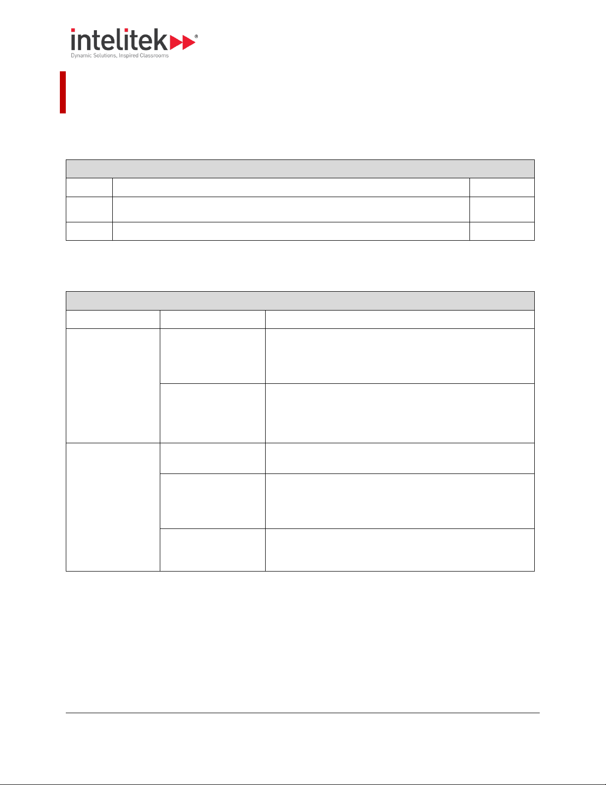
Section Contents: Safety Guidelines
Section
Name
Page
1.1
Detailed Safety Guidelines
1
1.2
Safety Checklist
5
Info Table: Safety Guidelines
Category
Guideline
Comment
Operator knowledge
and authorization
Review the User’s
Guide.
Read this guide carefully before you use the milling center and
keep it readily accessible for quick reference. Know the intended
applications and limitations of the milling center as well as its
hazards.
Keep untrained visitors
away from the
equipment.
Children and visitors unfamiliar with the hazards of rotating
machinery should always be kept away from the work area.
Behavior
Do not overreach.
Keep your footing and balance at all times so you won’t fall
against or clutch at the moving machine.
Do not operate the
machine under the
influence of alcohol or
drugs.
Alcohol or drugs may impair your judgment and reaction time,
which could contribute to an on-the-job accident.
Avoid distractions
while running the
machine.
Use simple common sense and pay attention while operating
any piece of machinery.
1. Safety Guidelines
The safety rules presented here should be reviewed and practiced by all operators of the ProMill 8000
milling center.
This section presents the following information:
1.1. DETAILED SAFETY GUIDELINES
The table below provides detailed safety instructions.

1 Safety Guidelines
1.1 Detailed Safety Guidelines
2
Work Area
Keep the work area
clean.
Cluttered work areas and bench tops invite accidents.
Avoid a dangerous
environment.
Don’t use the milling center in damp or wet locations. Never
operate electrical equipment in the presence of volatile and
flammable petroleum-based solvents and lubricants.
Keep coolant away
from electrical
components.
Do not allow coolant to splash into or near the computer.
Clothing and Hair
Avoid loose hair and
clothing.
Don't wear loose clothing or jewelry that can get caught in
moving parts. Wear a hat or hair net, or tie your hair back to
keep it away from moving parts.
Safety Equipment
Wear safety glasses.
During operation any power tool can throw foreign objects and
harmful chemicals into your eyes. Always put on safety glasses
or eye shields before starting up the milling center. Safety
glasses or shields should provide full protection at the sides, as
well as the front of the eyes.
Ground all tools.
The milling center has an AC power cord terminated by a threeprong plug. The power cord should be plugged into a threehole, grounded receptacle. If a grounding adapter is used to
accommodate a two-prong receptacle, the adapter wire must
be attached to a known ground. Never remove the third prong
from the plug on the AC power cord.
Keep the safety door
closed while machine
is in motion.
The safety door should remain in place whenever the spindle
motor is on or the cross slide is moving.
Remove adjusting keys
and wrenches.
Make it a habit to check that keys and adjusting wrenches are
removed from the milling center before using the machine.
Emergency Stop
Stopping the machine.
Before you run the ProMill 8000 for the first time, you should
know how to stop the machine should an emergency situation
arise.
To initiate an emergency stop on the milling center, either:
Press the Emergency Stop button, or
Turn the machine off at the power switch.
In non-emergency situations, the machine can be stopped in the
following ways:
Simultaneously press the Control and Space Bar keys
on the computer keyboard
Activate one of the limit switches
Activate the safety door interlock switch.
When to use the
Emergency Stop.
You should use the Emergency Stop button to disconnect power
to the milling center when faced with a problem such as a tool
breaking or a collision occurring, and while performing routing
operations, such as when changing tools or mounting or
removing a workpiece.

1 Safety Guidelines
1.1 Detailed Safety Guidelines
3
Using the machinemounted emergency
stop button.
There is an Emergency Stop button located on the front panel of
the milling center; it has an oversized red cap.
To engage: Press the button in.
To release: Turn the button clockwise, it will pop out on its own.
Using the software
stop button.
The execution of the part program can be interrupted by
pressing the Control and Spacebar buttons on the computer
keyboard. Unlike using the Emergency Stop button, this method
of stopping the milling center does not cause the software to
lose track of the tool position.
Operation Rules
General
Proper setup of the milling center is essential for safe milling.
These procedures must be followed each time a new tool is
mounted. General setup requirements for the milling center
include checking components for cleanliness and lubrication,
mounting the cutting tool, mounting the workpiece, and setting
the spindle rotation speed.
Avoid accidental
starting.
Make sure the power switch is off before plugging in the milling
center power cord.
Check milling machine
components.
Always examine the machine to be sure that the work area is
free of shavings and particles from previous operations. Remove
such debris from the milling machine to avoid possible binding
of components which may result in possible damage to the
milling machine, the workpiece, or the operator.
Always make sure the machine is properly lubricated.
Do not force a tool.
Select the feed rate and depth of cut that are best suited to the
design, construction, and purpose of the cutting tool. It is
always better to take too light a cut than too heavy a cut.
Use the right tool.
Select the type of cutting tool best suited to the milling
operation. Don't force a tool or attachment to do a job it wasn't
designed for.
Maintain cutting tools
in good condition.
Keep cutting tools sharp and clean. Lubricate and clean milling
center components on a regular basis.
Mount the cutting tool
correctly.
Each cutting tool used in the milling operation must be sharp
and properly installed in the spindle. The cutting edge of the
tool must be on the centerline or just below the centerline
(0.004 inch or 0.1 mm maximum) of the axis of rotation of the
milling machine
Secure the workpiece.
Be certain that the workpiece is firmly clamped to the table or
secured in a vice.
Tighten all holding,
locking and driving
devices.
Tighten the work holders and tool holders. Do not over tighten
these devices. Over tightening may damage threads or warp
parts, thereby reducing accuracy and effectiveness.
Turn the spindle by
hand before starting.
Manually turning the spindle allows you to safely determine
that the tool will not hit the milling center bed, cross slide, or
stock on start up.

1 Safety Guidelines
1.1 Detailed Safety Guidelines
4
Set the spindle rotation
speed.
The ProMill Milling Center is equipped with an electronically
controlled spindle motor which produces a comprehensive
range of spindle rotation speeds. Speed can be set with the
Control Software or by using an S code in the NC program.
Always use a safe spindle speed.
Accessories
Use recommended
accessories only.
To avoid stressing the milling center and creating a hazardous
milling environment, use only those accessories designed for
use with the ProMill 8000, available through Intelitek
Corporation.

1 Safety Guidelines
1.2 Safety Checklist
5
Post copies of this checklist in the work area. Verify that all items are checked-off prior to each
operation of the ProMill milling center.
1.2. SAFETY CHECKLIST
Before you enter the work area:
Put on safety glasses.
Tie back loose hair and clothing.
Remove jewelry including rings, bracelets and wristwatches.
Before milling a part:
Make sure you have the correct tool for the job.
Secure the tool properly.
Make sure all tool positions have been properly initialized.
Verify the NC program on the computer.
Remove all loose parts and pieces from the machine.
Remove adjusting keys and wrenches from the machine.
Close the safety door.
Only operate the machine after being properly trained in its use.
Perform a dry run:
Make certain there is no workpiece in place.
Run the NC program to make sure all the moves make sense before running the program
with a workpiece in place.
After completing the dry run, properly secure the workpiece to the machine.
Keep fluids away from all electrical connections, electronic or electrical devices, the computer, and
nearby electrical outlets.
While milling a part:
Do not touch moving or rotating parts.
Press the Emergency Stop button before opening the safety door.
Only open the safety door after the spindle has stopped rotating.
Press the Emergency Stop button whenever changing tools or mounting or removing a workpiece.
Release the Emergency Stop button only after closing the safety door.
Keep all unauthorized persons away from the work area.
2 Introducing the ProMill 8000
2.1 Overview of Standard Features
6
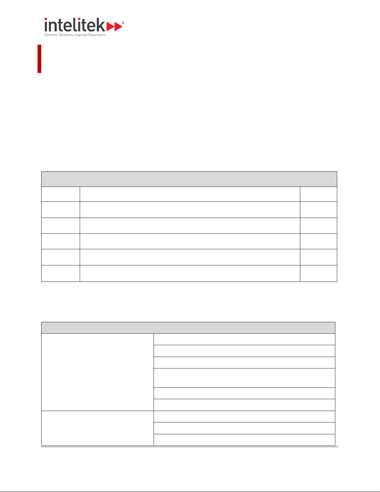
Section Contents: Introducing the ProMill 8000
Section
Name
Page
2.1
Overview of Standard Features.
6
2.2
ProMill 8000 Components
8
2.3
Overview of CNCBase/Motion Control Software.
12
2.4
Standard Accessories
12
2.5
Optional Accessories
13
Info Table: Standard Features
Network and software features
Ethernet-based control
PC-based CNC software
EIA RS-274D standard G&M code programming
A built-in full-screen NC program editor with graphic tool path
verification
Multiple tool programming
Help functions on screen
Standard hardware features
4th axis ready
Brushless spindle motor
Pneumatic drawbar
2. Introducing the ProMill 8000
The ProMill 8000 is a versatile PC-based CNC milling center that enables you to deliver robust instruction
in computer numerical control and advanced manufacturing.
The ProMill 8000 comes equipped with 3-axis stepper motors, ball screws, a variable speed A/C
powered brushless spindle motor, limit/home switches, and an ISO 20 taper spindle with a 10 mm
maximum tool diameter and 150 mm throat.
This CNC system requires no assembly and is ready to run on an Ethernet port on a standard PC, and fits
comfortably into any classroom without sacrificing features.
Like larger industrial machines, the ProMill 8000 uses EIA, ISO, and Fanuc-compatible G&M code
programs to cut parts in a variety of materials.
This section presents the following information:
2.1. OVERVIEW OF STANDARD FEATURES
Some of the ProMill Milling Center’s most notable hardware and software features are listed in the table
below:

2 Introducing the ProMill 8000
2.1 Overview of Standard Features
7
Standard milling specifications
y-axis travel of 6 inches (152 mm)
X-axis travel of 10.24 inches (260mm)
Z-axis travel of 7.09 inches (180mm)
Feed rates up to 20 IPM (500mm/min) (rapid traverse up to 79 IPM
(2000mm/min))
Computer-controlled spindle speeds from 100 to 5,000 RPM
Safety features
Full enclosure with automatic safety door lock
Automatic diagnostics and power cut off protection
Safety door and limit switches
Emergency stops from the milling center and computer keyboard
Machine ready optional accessories
Coolant ready
Jog pendant ready
Robotic integration ready with 6 inputs, 6 outputs
2 Introducing the ProMill 8000
2.2 ProMill 8000 Components
8
Section Contents: Components
2.2.1 External View, pg. 9
2.2.2 Right Side Panel, pg. 10
2.2.3 Enclosure , pg. 11
2.2.4 Rear Pneumatics Panel, pg. 12
2.2. PROMILL 8000 COMPONENTS
This section shows the location of major components of the ProMill 8000, arranged by the view from
which they are visible:
2 Introducing the ProMill 8000
2.2 ProMill 8000 Components
9
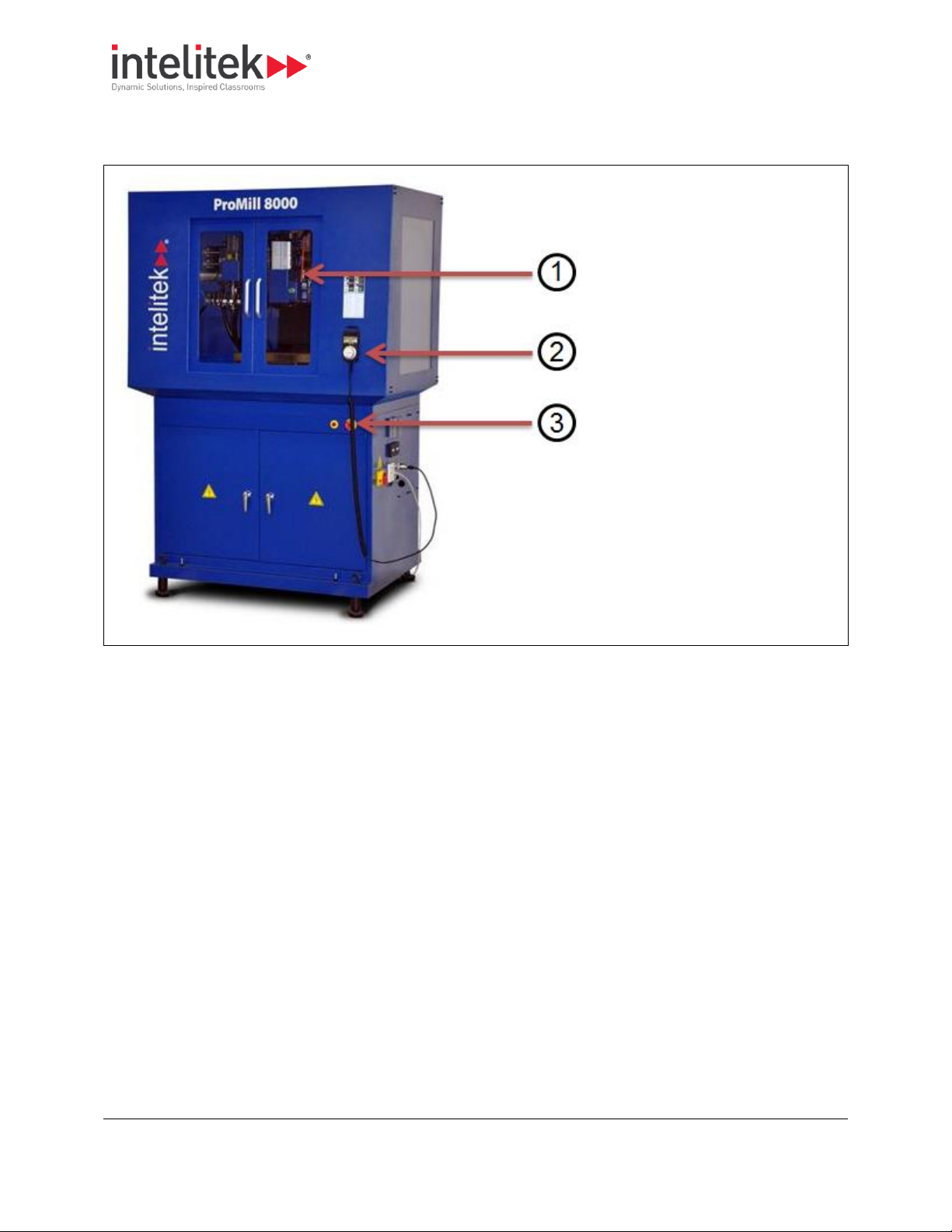
1. Safety shield (door)
2. Jog pendant (optional)
3. Emergency stop switch
2.2.1. External View
The external view is shown below.
Notes:
The Safety door encloses the milling area to help protect the operator from flying chips. A
magnetic shield interlock switch prevents the machine from operating with the shield open.
The Emergency Stop button is used to halt machine operation. When pushed, machine
operation stops immediately. To resume operation, the button must be rotated clockwise and
will then pop out on its own. It is important that this button be pushed in (i.e. engaged) before
performing any manual operation, such as changing the stock or tooling.
2 Introducing the ProMill 8000
2.2 ProMill 8000 Components
10
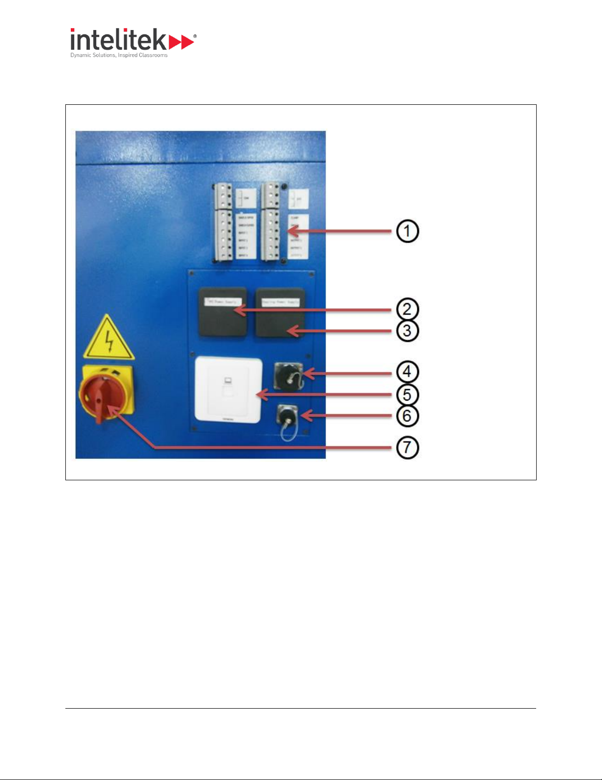
1. I/O ports
2. PC power supply
3. Coolant power
supply
4. Jog pendant port
5. Ethernet port
6. FANUC panel port
7. On/off switch
2.2.2. Right Side Panel
The graphic below shows the machine as viewed from the right side.
2 Introducing the ProMill 8000
2.2 ProMill 8000 Components
11
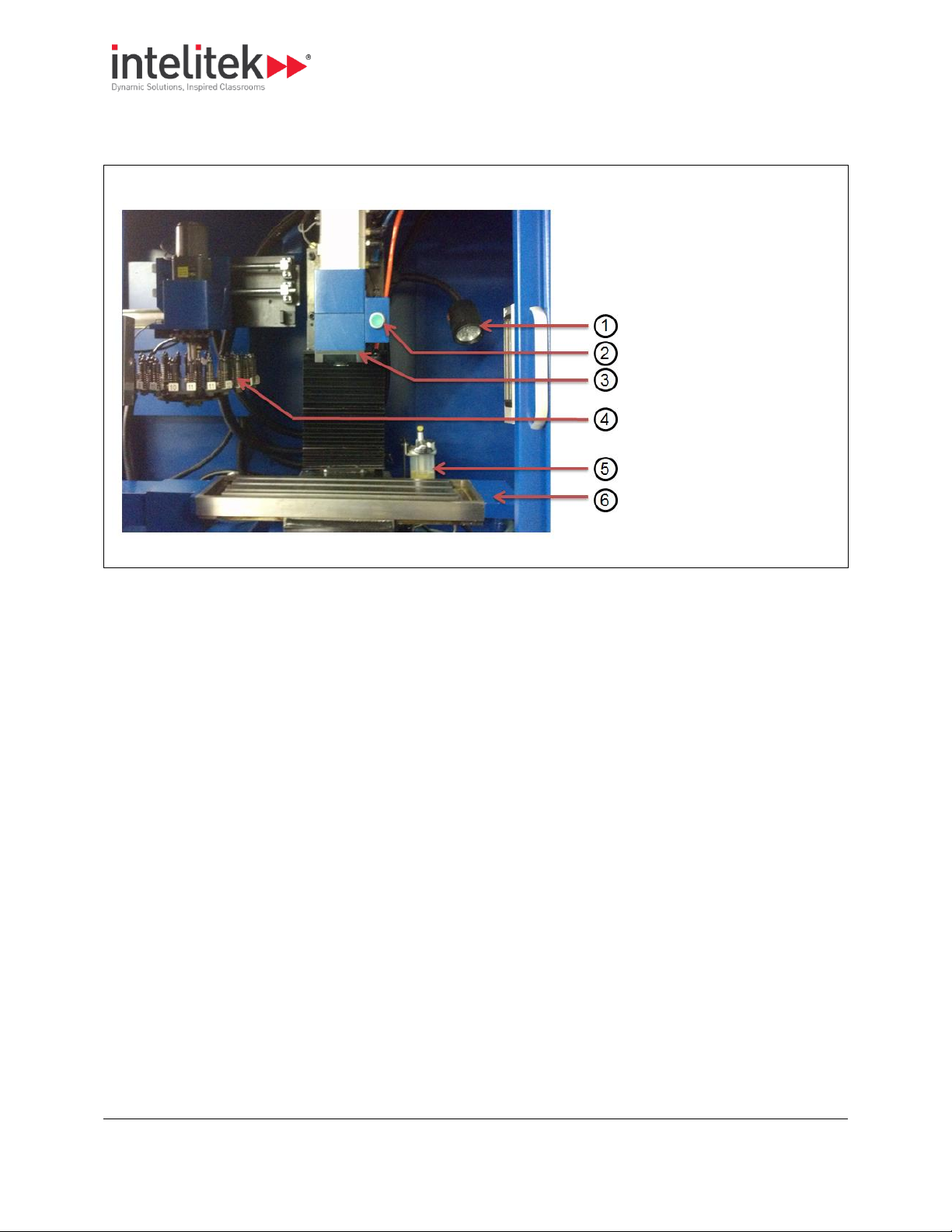
1. Work light
2. Tool release button
3. Spindle Head
4. Automatic tool changer
(optional)
5. Lubricant reservoir
6. Cross-slide
2.2.3. Enclosure
The graphic below shows the contents exposed by opening the safety shield.
2 Introducing the ProMill 8000
2.4 Standard Accessories
12
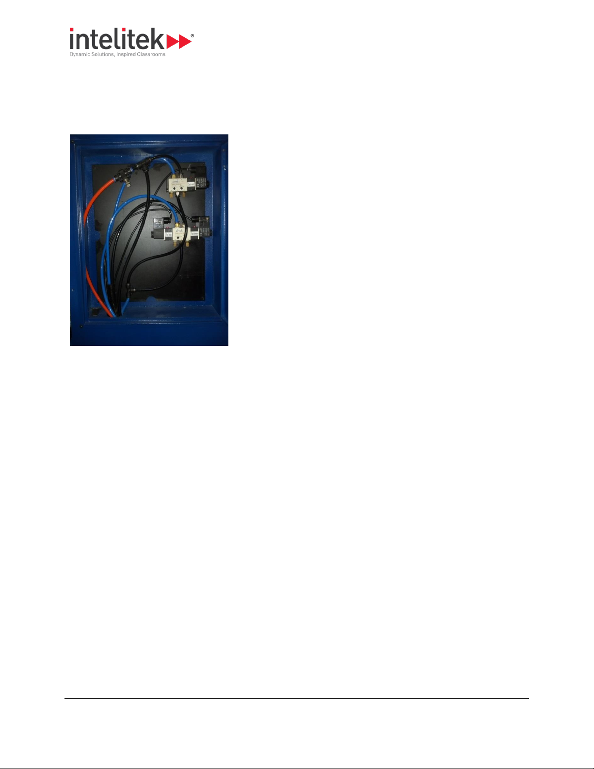
2.2.4. Rear Pneumatics Panel
The pneumatic controls for the 12 station tool changer (optional) and drawbar air-blast are located in
the rear pneumatics panel. For more information, see 4.4 Adjusting and Maintaining the Pneumatic
Systems, pg. 39.
2.3. OVERVIEW OF CNCBASE/MOTION CONTROL SOFTWARE
The heart of the ProMill 8000 milling center is the control software (CNCMotion or CNCBase) that runs
on your computer. Using industry standard EIA RS- 274D NC codes, the control software provides for
two-axis CNC programming and milling.
The control software is extremely easy to use with all necessary functions readily available to run a part
program.
CNCBase and CNCMotion differ only in that CNCMotion provides 3D simulation of the milling procedure.
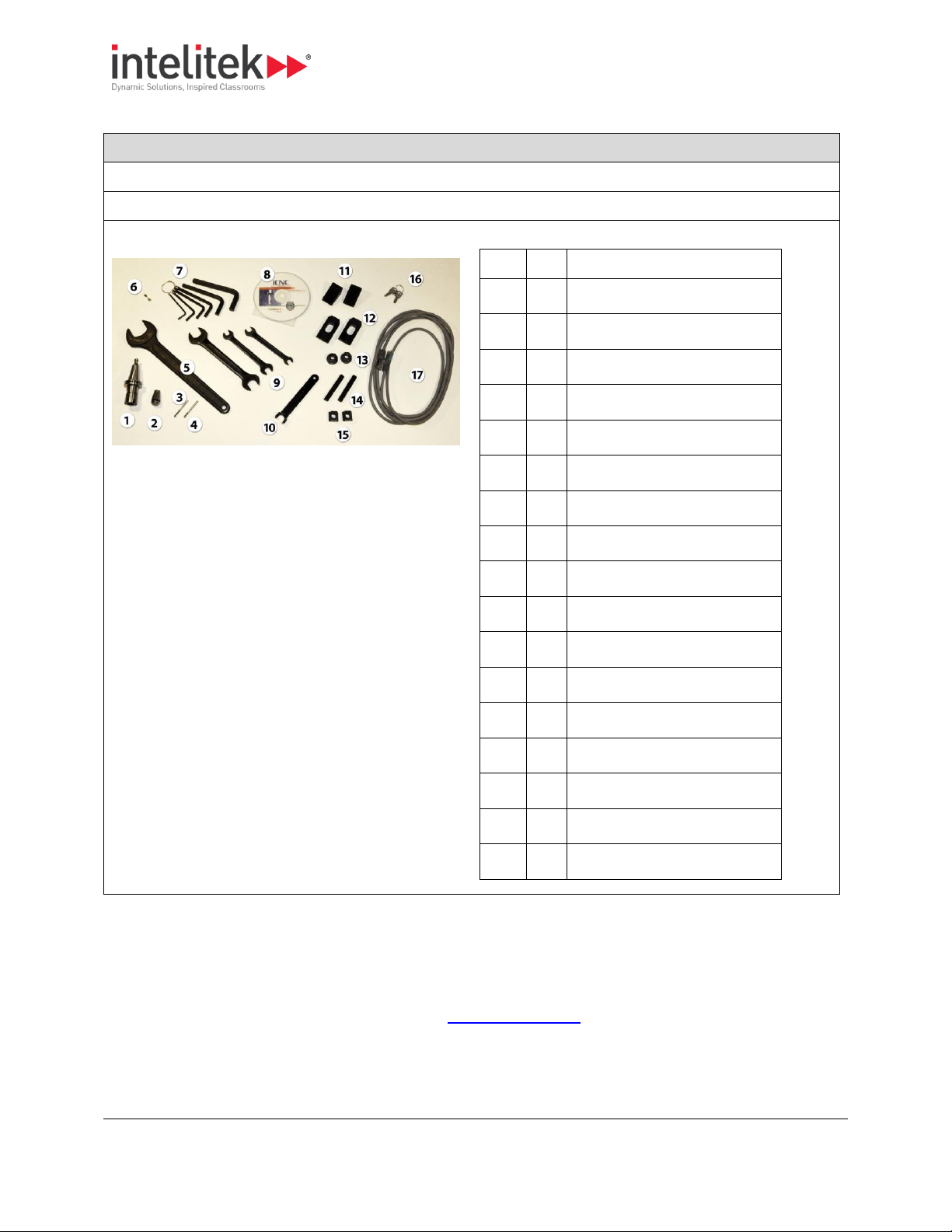
2.4. STANDARD ACCESSORIES
The accessory kit supplied with the milling center contains all the tools and hardware necessary for
installing and maintaining the milling center. Additional tool holding devices and tools are available as
options.
2 Introducing the ProMill 8000
2.5 Optional Accessories
13
Info Table: Standard Accessories
One shot lubrication system
Internal work light
Milling center accessory package:
Item
Qty
Description
1 1 ISO 20 Tool holder
2 1 ER 16 Collet - 4mm diameter
3 1 3mm End mill 3mm shank
4 1 1/8" End mill 1/8" shank
5 1 Tool holder wrench - 30mm
6 1 5mm x 20mm Fuse
7 1 Allen wrenches, set of 6
8 1 CNCBase control software
9 1 Open-ended wrenches, set of 3
10 1 Tool holder nut wrench
11 2 Step block
12 2 Step clamp
13 2 Hex-head nut
14 2 Threaded shank
15 2 T-nut
16 2 Electrical panel keys
17 1 Ethernet cable
This table below lists the standard accessories supplied with the ProMill 8000.
2.5. OPTIONAL ACCESSORIES
Intelitek offers a variety of milling center accessories, CAM software, curriculum, and documentation.
For more information about these products call your Intelitek dealer, call Intelitek directly at (800)2212763 or (603) 413-2600, or browse our web site www.intelitek.com.
3 Installing the Hardware and Software
3.1 Preparing for Installation
14
Procedure Outline: Installation
No.
Step
Section
Page
1
Prepare your hardware for installation.
3.1
14
2
Install the hardware.
3.2
18
3
Install and configure the software.
3.3
20
Section Contents: Installing the Hardware and Software
Section
Name
Page
3.4
Contacting Technical Support
33
3.5
Returning Defective Products
33
Procedure Outline: Preparing for Installation
No.
Step
Page
1
Verify that the computer to be used with the milling center meets minimum requirements.
14 2 Prepare a work space for the milling center.
15
3
Remove the crating.
15 4 Unpack and set up the milling center.
16
5
Check your shipment to ensure that all items ordered are present and undamaged.
16
6
Register your milling center to activate the warranty.
17
3. Installing the Hardware and Software
This section presents instructions for installing the hardware and software components.
This section also presents the following information.
3.1. PREPARING FOR INSTALLATION
This section presents instructions for preparing the work space and machine for installation.
3.1.1. Verifying Computer Requirements
Use the checklist below to ensure that the computer that will be attached to the milling center meets
minimum requirements.
3 Installing the Hardware and Software
3.1 Preparing for Installation
15
Checklist: Verifying Computer Requirements
Windows 7/Windows 8/Windows 10 - 32 or 64bit
512 MB RAM (1 GB Recommended)
CD-ROM
100 MB of available hard drive space (300 MB Recommended)
VGA graphics or better graphics display (minimum 256 colors)
Available Ethernet port
A mouse or other pointing device
ATX Power Supply (Recommended)
Note: Your operating system might have additional hardware requirements.
Checklist: Preparing the Work Space
For customers in the U.S.A.: A 120VAC, 15 Amp outlet
For international customers: A 220VAC, 8 Amp outlet
A personal computer running Windows 95 or Windows NT version 3.51 (or higher). See section 3.3.1
Verifying Computer Requirements, pg. 20, for a complete list of the necessary computer equipment.
Product Care
We recommend the use of a voltage surge protector and line filter to protect your computer
system.
Procedure: Removing the Crating
1. Inspect the crating for any visible signs of damage. If there is damage to the crating, contact the shipping
company and Intelitek Customer Support.
2. Cut any banding on the outside of the crate.
3. Remove the top of the crate.
4. Remove the sides of the crate.
Intelitek is not responsible for any damage caused during shipping when components are
not returned in the original packing materials.
Store the packing materials at least until the installation is complete and proper operation
has been verified.
3.1.2. Preparing the Work Space
Use the checklist below to ensure that the work space is ready for the installation of the machine.
3.1.3. Removing the Crating
Follow the procedure below when removing the crating after delivery of the product.

3 Installing the Hardware and Software
3.1 Preparing for Installation
16
Procedure: Unpacking and Setting up the Milling Center
1. Position the pallet near the location at which you'll set the milling center.
2. Remove the staples that attach the bottom of the cardboard container to the pallet.
3. Cut the banding around the container.
4. Lift the cardboard cover off the top of the container.
5. Remove the sides of the container.
6. Inspect the milling center chassis for signs of visual damage such as a broken shield, a dent in the chassis,
or damaged cables.
7. Call Intelitek Customer Support if any damage is noted.
8. Remove the four bolts that hold the milling center base to the pallet, using a 19mm wrench.
9. Store the bolts and other packaging materials, in case the product has to be returned or transported.
10. Lift the milling center off of the pallet and place it at its designated location.
11. Position the milling center correctly for milling.
12. Remove the protective paper from the safety door.
13. Open the front door and remove the components from the enclosure.0.
Procedure: Checking your Shipment
1. Locate the packing slip. This slip lists all of the items you should have received with your milling center.
2. Check that all items on the packing slip are present. See the checklist below.
3. Contact Intelitek Customer Support immediately if any item is missing. 0.
Checklist: Checking your Shipment
No.
Item
1
ProMill 8000 Milling Center
2
Installation disk for CNCBase/Motion software
3
Documentation pack
Take Note
3.1.4. Unpacking and Setting up the Milling Center
Follow this procedure for unpacking and setting up the milling center.
3.1.5. Checking your Shipment
Follow this procedure for checking your shipment once unpacked.
Use this checklist to ensure that all items listed on the packing slip are present in the delivery.

3 Installing the Hardware and Software
3.1 Preparing for Installation
17
4
Accessory kit
The accessory kit should include the following:
Item
Qty
Description
1 1 ISO 20 Tool holder
2 1 ER 16 Collet - 4mm diameter
3 1 3mm End mill 3mm shank
4 1 1/8" End mill 1/8" shank
5 1 Tool holder wrench - 30mm
6 1 5mm x 20mm Fuse
7 1 Allen wrenches, set of 6
8 1 CNCBase control software
9 1 Open-ended wrenches, set of
3
10 1 Tool holder nut wrench
11 2 Step block
12 2 Step clamp
13 2 Hex-head nut
14 2 Threaded shank
15 2 T-nut
16 2 Electrical panel keys
17 1 Ethernet cable
5
Additional accessories ordered
Procedure: Registering Your Milling Center
1. Locate the box that contains the documentation and installation disk.
2. Locate the registration card within that box.
3. Complete the card, printing all information clearly.
4. Return the card to Intelitek Customer Support at the address below,
3.1.6. Registering Your Milling Center
Follow this procedure to register your milling center.
3 Installing the Hardware and Software
3.2 Installing the Hardware
18
Intelitek Customer Support
18 Tsienneto Road
Derry, NH 03039
USA
or fax to 603-625-21370.
Procedure Outline: Hardware Installation
No.
Step
Section
Page
1
Connect the milling center to a computer.
3.2.1
18 2 Connect the milling center to a power source.
3.2.2
19 3 Install additional accessories purchased.
3.2.3
19
Safety
Do not connect power to the milling center or the computer until instructed to do so in the
following procedures.
Procedure: Connecting the Milling Center to a Computer
1. If not done previously, verify that the computer you are planning to use meets minimum requirements.
See 3.1.1 Verifying Computer Requirements, pg. 14.
3.2. INSTALLING THE HARDWARE
This section presents instructions for installing the ProMill 8000 hardware.
3.2.1. Connecting the Milling Center to a Computer
Follow the procedure below to connect the milling center to a computer.
You will connect the milling center directly to a computer. Connection to the network (if required) is
provisioned by the computer.
3 Installing the Hardware and Software
3.2 Installing the Hardware
19
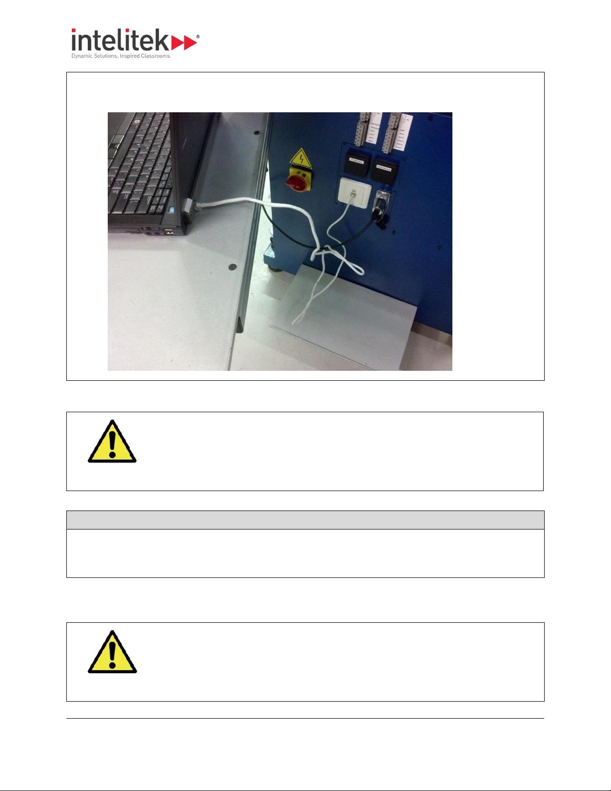
2. Use a cable with 8P8C (RJ-45) connectors at both ends to connect the milling center to the computer, as
shown below. 0.
Safety
The milling center has an AC power cord terminated by a three-prong plug. The power cord
should be plugged into a three-hole, grounded receptacle. If a grounding adapter is used to
accommodate a two-prong receptacle, the adapter wire must be attached to a known
ground. Never remove the third prong from the plug on the AC power cord.
Procedure: Connecting the Power
1. Ensure that the milling center’s power switch, located at its side, is set to the OFF position.
2. Connect the power cord from the milling center to the power source. 0.
Safety
To avoid stressing the milling center and creating a hazardous milling environment, use only
those accessories designed for use with the ProMill milling center, available through Intelitek
Corporation.
3.2.2. Connecting the Power
Follow the procedure below to connect the milling center to a power supply.
3.2.3. ProMill 8000 Installing Accessories
Each accessory kit is supplied with an installation guide.
3 Installing the Hardware and Software
3.3 Installing the Software
20
Product Care
Complete the hardware and software installation procedures (see 3.3 Installing the Software
below), and test the functioning of the basic machine, before installing accessories.
Procedure Outline: Software Installation
No.
Step
Section
Page
1
Ensure that your computer meets the minimum requirements.
3.3.1
20 2 Run the installation to install the software.
3.3.2
21
3
Configure the software for your machine and accessories.
3.3.4
25 4 Configure the IP address of the milling center
3.3.5
29
Section Contents: Installing the Software
Section
Name
Page
3.3.6
Uninstalling the Software
31
3.3. INSTALLING THE SOFTWARE
This section presents instructions for installing the control software (CNCMotion or CNCBase) on the
computer.
This section also presents the following information:
3.3.1. Verifying Computer Requirements
If not done previously, verify that the computer you are planning to use meets the minimum
requirements. See 3.1.1 Verifying Computer Requirements, pg. 14.
If installing the software on a computer to be used only for writing and verifying NC programs, but not
for interacting with the hardware itself, the requirement for LAN cards is not relevant.
3 Installing the Hardware and Software
3.3 Installing the Software
21
Procedure: Running the Installation
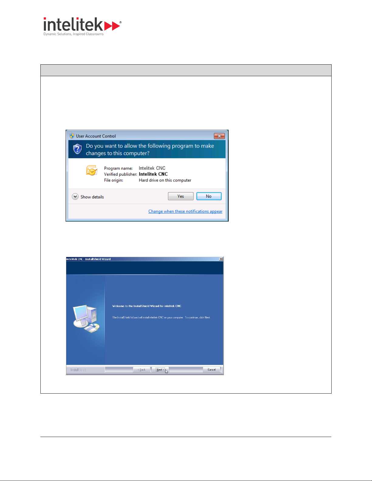
1. Insert the installation disk into the CD/DVD drive. The installation program should open automatically.
If the installation does not open automatically, navigate to the Install folder and launch the program
iCNC.exe.
2. If the User Account Control message displays, click Yes.
The installation begins and the Welcome screen is displayed.
3. Click Next.
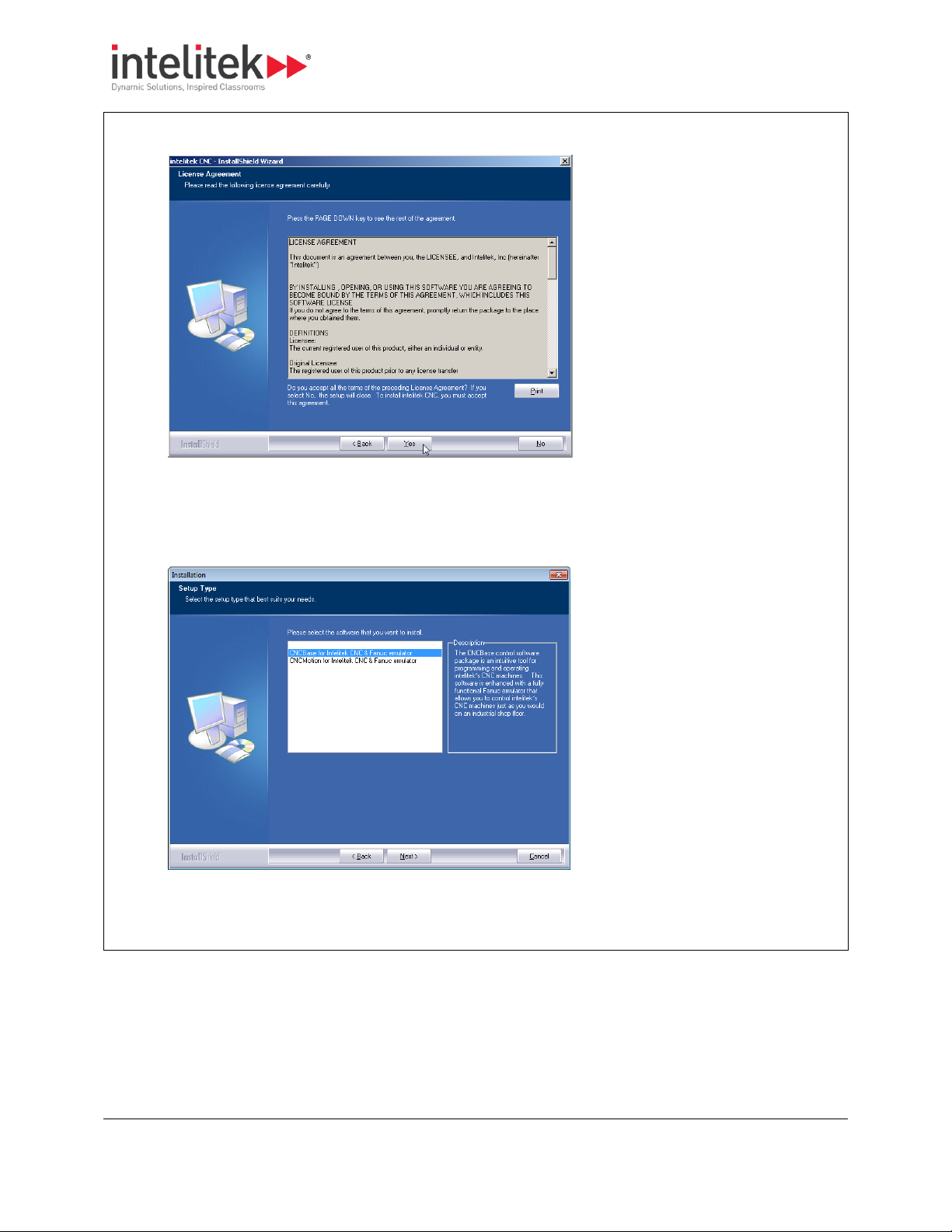
The License Agreement is displayed.
3.3.2. Running the Installation
Follow the procedure below to run the installation.
3 Installing the Hardware and Software
3.3 Installing the Software
22
4. Click Yes to accept and continue.
The Software Selection screen is displayed.
5. Select the software to install. It is important that the software you select here matches the license you
have purchased.
6. Click Next.
The Machine Selection screen is displayed.

3 Installing the Hardware and Software
3.3 Installing the Software
23
7. Select the machine you will be using. It is important that the machine selected matches the license you
have purchased.
8. Click Next.
The Configuration Options screen is displayed.
9. Select whether the configuration and sample programs are to be exclusive to each user (first option) or
common to all users (second option). The first option is recommended when running software in
simulation mode. The second option is highly recommended when running software with a physical CNC
machine.
10. Click Next.
The Choose Destination Location screen is displayed.

3 Installing the Hardware and Software
3.3 Installing the Software
24
11. If necessary, click Browse to change the destination folder.
12. Click Next.
The Ready to Install screen is displayed.
13. Click Install.

3 Installing the Hardware and Software
3.3 Installing the Software
25
14. Wait while installation is performed.
The InstallShield Wizard Complete screen is displayed.
15. Select Yes, I want to restart my computer now.
16. Click Finish.
Your computer will restart and installation will be finalized.0.
Procedure Outline: Configuring the Software
No.
Step
Section
Page
1
Run the configuration program.
3.3.4.1
20 2 Change configuration settings using the configuration program.
3.3.4.2
21
3.3.3. Licensing the Software
For details on licensing your software and managing or transferring your license, refer to the Licensing
Help document that can be found in the Books folder of the software installation disk. You can also
access the Licensing Help document by clicking the Help button during software registration.
Note that CNCBase does not require registration. If you have purchased CNCMotion, that software does
require registration.
3.3.4. Configuring the Software
The installation program automatically configures most software parameters based on the selections
you make during installation.
The Configuration Program can be used to:
Modify selections made during installation.
Configure machine accessories installed.
This section presents instructions for configuring the control software (CNCMotion or CNCBase) on the
computer.

3 Installing the Hardware and Software
3.3 Installing the Software
26
3
Add optional accessories to the machine.
3.3.4.3
28
Procedure: Running the Configuration Program
1. Ensure that CNCBase/Motion is not currently running.
2. Click the Windows Start button.
3. Click All Programs.
4. Locate and click the CNCBase/Motion for Intelitek CNC & Fanuc emulator folder.
5. Click CNCBase/Motion Configuration.0.
The CNC Configuration window displays.
3.3.4.1. Running the Configuration Program
The Configuration Program is launched from your Windows Start menu.
If you try to launch the Configuration Program while the CNCBase/Motion software is open, you will be
asked to close CNCBase/Motion first.

3 Installing the Hardware and Software
3.3 Installing the Software
27
Procedures: Using the Configuration Program
To
Instructions
View all available settings
Click the tabs at the top of the window.
Access online help
Click the Help button.
Save changes made
Click OK. Clicking OK will close the configuration program.
Make all required changes before clicking OK.
Info Table: CNC Configuration Program Tabs
Tab
Main Options
Welcome
Units (Inch or Metric)
3.3.4.2. Using the Configuration Program
The table below summarizes the use of the configuration program.
The table below summarizes the configuration options available on each of the four tabs of the CNC
Configuration Program.

3 Installing the Hardware and Software
3.3 Installing the Software
28
General
Run in offline (simulation) or online
mode. For more information on
switching between offline and
online modes, see 5.2 Selecting
Online or Simulation Mode, pg. 44.
NC programming settings
User inputs mapping
Options
Lists installed options and allows
you to install addition options. Click
Reinstall to install others.
For more information, see 3.3.4.3
Adding Installed Optional
Accessories, pg. 28.
Machine
Configuration
Allows you to select a different
machine, and to save and load
previously defined configurations.
3.3.4.3. Adding Installed Optional Accessories
Optional accessories are available for the ProMill 8000 (see 2.5 Optional Accessories, pg. 13). After
installing the accessory hardware, the control software must be reconfigured.
Detailed instructions are provided in the installation guide supplied with each accessory. General
instructions are provided below.

3 Installing the Hardware and Software
3.3 Installing the Software
29
Procedure: Configuring Control Software for New Accessory
1. Run the configuration program. (See 3.3.4.1 Running the Configuration Program, pg. 26.)
2. Click the Options tab.
3. Click Reinstall.
The Reinstall Options window is displayed.
4. Select the option to be added.
5. Click Reinstall.0.
The Reinstall Options window closes. The selected option is now listed in the Installed Options list.
Follow the procedure below to configure the control software for a new accessory.
3.3.5. Configuring the IP Address
Before using the hardware, you must configure its IP address on the network.
This utility configures the IP address of the computer’s LAN adapter.

3 Installing the Hardware and Software
3.3 Installing the Software
30
Take Note
You must have administrator access to your computer to run the Machine IP Changer
utility.
Take Note
To reconnect to the network over the LAN, you will need to restore the settings of your
LAN adapter.
Procedure: Configuring the IP Address
1. Run the Machine IP Configuration utility. To do so, locate the CNCBase/Motion for Intelitek CNC & Fanuc
emulator folder and click Machine IP Configuration.
2. Click Yes if asked for permission.
3. From the dropdown list, select the local area network or network card that you wish to use for the CNC
machine.
4. Click Continue.
Follow the procedure below to configure the IP address.

3 Installing the Hardware and Software
3.3 Installing the Software
31
5. Click Yes when asked for confirmation of your selection.
When the process is finished, Machine IP Changer displays the configuration for all active network
connections.
6. Click OK to close the program.0.
Procedure: Uninstalling the Software
1. Click the Windows Start button.
2. Click All Programs.
3. Locate and click the CNCBase/Motion for Intelitek CNC & Fanuc emulator folder.
4. Click Uninstall.
3.3.6. Uninstalling the Software
When necessary, follow the procedure below to uninstall the software.

3 Installing the Hardware and Software
3.3 Installing the Software
32
5. Click Yes if the User Account Control message displays.
The Uninstall Wizard is displayed, asking for confirmation.
6. Click Yes to uninstall CNCBase/Motion.
7. Wait while the software is uninstalled.
The Uninstall Complete window is displayed.
8. Select Yes, I want to restart my computer now.
9. Click Finish.
Your computer will restart and uninstallation will be finalized.0.

3 Installing the Hardware and Software
3.5 Returning Defective Products
33
Info Table: Requirements for Technical Support
The product serial number
The name of the owner of the product
The specifications of your computer (e.g. version of
Windows, hard drive size, clock speed, etc.)
Notes on any error messages received
Take Note
When you call, make sure you have access to both your milling center and your computer.
This will allow our technical support representatives to walk through the problem with you.
Info Table: Intelitek Technical Support Contact Details
Toll-free (U.S. only)
(800) 221-2763
Direct Dial
(603) 413-2600
e-mail
support@intelitek.com
Web site
www.intelitek.com
Take Note
Intelitek will not be responsible for any damage incurred during shipping when components
are not returned in the original packing materials.
Procedure: Returning Defective Products
1. Contact Intelitek Technical Support and describe the problem.
2. If the Technical Support representative decides that the product is defective and has to be returned, the
Technical Support representative will issue a Return Materials Authorization number (RMA). Store this
3.4. CONTACTING TECHNICAL SUPPORT
Should you require technical assistance, contact your local Intelitek dealer. If you are unable to resolve
your problem through your local dealer, free technical support is available by phone or email from 8:15
A.M. to 5:00 P.M. EST.
Make sure you have the following information gathered before contacting our Technical Support group.
Technical support contact details:
3.5. RETURNING DEFECTIVE PRODUCTS
Intelitek products (excluding software) carry a one-year limited warranty from date of purchase.
Defective products may be returned for repair or replacement according to the conditions outlined in
the Terms and Conditions of Sale agreement.
Follow the procedure below to return defective products.

3 Installing the Hardware and Software
3.5 Returning Defective Products
34
number safely.
3. Pack the product to be returned in its original packaging and crate, as was packed originally.
4. Write the RMA number and your return address on the outside of the product carton or crate. Failure to
do so can result in a delay in the return of your product.
5. Have the package returned to Intelitek’s offices, as directed by the Technical Support representative. 0.

4 Maintaining the ProMill 8000
4.1 Cleaning the Milling Center
35
Product Care
Preventative maintenance of the ProMill 8000 is essential for ensuring a long and troublefree service life.
Maintaining the Milling Center
Description
Section
Page
Keep the machine clean.
4.1
35
Maintaining individual milling machine components.
4.2
36
Follow a maintenance schedule.
4.3
38
Adjust the pneumatic systems.
4.4
39
Maintaining a computer in a shop environment.
4.4
39
Checklist: Cleaning the Milling Center
Remove all chips from the machine after every use.
Pay particular attention to the bellows. If chips build up on top of the bellows, they may fall behind the
bellows and interfere with ball screw operation.
Product Care
If you clean a component of the milling center that requires lubrication, make sure to
relubricate it after cleaning.
4. Maintaining the ProMill 8000
This section presents instructions for maintaining the milling center and computer.
4.1. CLEANING THE MILLING CENTER
Keeping your machine clean is the easiest and most important maintenance practice.

4 Maintaining the ProMill 8000
4.2 Maintaining Individual Milling Machine Components
36
Maintaining the Milling Center Components
Task
Section
Page
Maintaining the Milling Machine Bed
4.2.1
36
Maintaining the Milling Machine Bed Linear Bearings
4.2.2
37
Maintaining the Ball Screw
4.2.3
37
Maintaining the Spindle Motor Belt
4.2.4
38
Product Care
Use 15 weight way oil only.
4.2. MAINTAINING INDIVIDUAL MILLING MACHINE COMPONENTS
Each of the milling center’s major components must undergo routine maintenance.
This section provides maintenance instructions for each major component.
These tasks provide maintenance instructions for each major component:
4.2.1. Maintaining the Milling Machine Bed
The milling machine bed, saddle, and ball screw all require constant lubrication to prevent wear and
rust. The ProMill 8000 is supplied with a one-shot system that simplifies lubrication of these
components.

4 Maintaining the ProMill 8000
4.2 Maintaining Individual Milling Machine Components
37
Guidelines: Lubricating the Milling Machine Bed
B
Operate the one-shot lubricating
system before each use.
To operate, pull on the handle of
the one-shot lubricating system
and release.
Keep the reservoir filled with 15
weight way oil.
Maintain a film of lubricant on the
surface of the milling machine bed
to minimize friction and wear.
Ensure that all non-painted
surfaces on the milling machine
are coated with oil to prevent rust.
Follow the guidelines below to ensure proper lubrication of the milling machine bed.
4.2.2. Maintaining the Milling Machine Bed Linear Bearings
Play in the table could indicate that the milling machine bed bearings require adjustment. The bearings
are factory-adjusted and should be checked at least every three months.
Contact your Intelitek customer service group for maintenance or service instructions.
4.2.3. Maintaining the Ball Screw
The ProMill 8000 Milling Center uses pre-loaded ball screws on both axes. The screws are lubricated at
the factory with a special long-life, waterproof ball screw lubricant. Additionally, the ball screw is
lubricated via the one-shot lubrication system.
One-shot lubrication should be performed before each use of the machine. See 4.2.1 Maintaining the
Milling Machine Bed, pg. 36, for instructions.

4 Maintaining the ProMill 8000
4.3 Maintenance Schedule Summary
38
Product Care
Call Intelitek Customer Service if the belt makes a squealing sound.
Guidelines: Maintenance Schedule
Continuously
Before Every
Use
After Every Use
Every 2 Months
Every 3 Months
Clean chips from
the milling
center
X
Coat exposed
surfaces with
light oil
X
Activate the oneshot lubrication
system
X
Maintain the
level of 15
weight way oil in
the one-shot
lubricating
system
X
Check and adjust
the milling
machine bed
linear bearings
X
4.2.4. Maintaining the Spindle Motor Belt
The spindle motor belt will wear out quickly if it becomes loose. If a belt squeals at slow speeds, it may
be loose or worn.
The spindle drive belt is inside the spindle head.
4.3. MAINTENANCE SCHEDULE SUMMARY
Follow the maintenance schedule outlined in the table below.

4 Maintaining the ProMill 8000
4.4 Adjusting and Maintaining the Pneumatic Systems
39
1. Drawbar regulator
2. Airblast
3. ATC regulator
Section Contents: Adjusting and Maintaining Pneumatic Systems
Section
Name
Page
4.4.1
Adjusting the Flow Controls
40
4.4.2
Adjusting the Air Pressure
40
4.4.3
Maintaining the Pneumatic Oil
40
4.4. ADJUSTING AND MAINTAINING THE PNEUMATIC SYSTEMS
Both the ATC and the drawbar air-blast are pneumatically powered. The pneumatic controls for both
systems are located in the rear pneumatics panel, as shown below.
This section presents the following information:

4 Maintaining the ProMill 8000
4.4 Adjusting and Maintaining the Pneumatic Systems
40
Info Table: Adjusting Pneumatic Flow Controls
Orange Pipe
Turn Clockwise (Close)
Reduce air-blast pressure
Turn Counter-clockwise (Open)
Increase air-blast pressure
1. Pressure control unit
2. Pressure gauge
3. Oil chamber
4. Filter/dryer vial
4.4.1. Adjusting the Flow Controls
The three flow control units are located in the rear pneumatics panel. The flow control units are
adjusted as follows:
4.4.2. Adjusting the Air Pressure
The air pressure should be set to 80 psi. The air pressure is adjusted using the control unit on the
regulator, located on the right side of the machine.
4.4.3. Maintaining the Pneumatic Oil
The oil flow rate is factory-adjusted and does not require maintenance.
The oil level in the oil chamber (see picture above) should be checked regularly and filled when empty.
Use standard pneumatic tool oil only.

4 Maintaining the ProMill 8000
4.5 Maintaining the PC in a Shop Environment
41
Guidelines: Maintaining the PC in a Shop Environment
Keep the computer and peripherals (mouse, keyboard, external drive, printer, etc.) out of direct sunlight,
away from sources of heat, and in a relatively clean environment (i.e., not right next to the foundry room).
Keep liquids (soda, coffee, cutting fluid, grease) away from the computer and peripherals.
Keep oil, grease, metal chips and excess dust away from the computer, keyboard and other peripherals.
Consider erecting a clear plastic shield between the computer and the milling machine to keep chips off
the computer.
Use grounded three-prong outlets for the computer and peripherals. Take precautions against current
overload. A line-surge suppression unit can be purchased at your local computer store to help alleviate
this problem.
Don’t block the vent holes in the computer or drives; they are required for air circulation.
4.5. MAINTAINING THE PC IN A SHOP ENVIRONMENT
Maintaining a personal computer and software in a shop environment requires extra precautionary
measures. See your owner’s manual for maintenance procedures specific to your computer.
Follow the guidelines listed in this table.

5 Using the Control Software
5.1 Launching the Control Software
42
Section Contents: Control Software
Section
Name
Page
5.1
Launching the Control Software
42
5.2
Selecting Online or Simulation Mode
44
0
Software Interface
45
5.4
Homing
61
5.5
Opening an NC File
62
5.6
Verifying an NC Program
64
5.7
Running an NC Program
71
5.8
Accessing Help
72
Safety
1. The safety door should be closed, and the Emergency Stop button released, before
launching the software in on-line mode.
2. The milling center must be powered up and connected to the computer before
launching the software in on-line mode.
3. Review the complete guidelines in chapter 1 Safety Guidelines, pg. 1.
Procedure: Launching the Control Software
1. If you intend to use the milling center, follow the safety information above.
2. Click the Windows Start button .
3. Click All Programs.
5. Using the Control Software
The control software, CNCBase or CNCMotion, is used to control all aspects of machine function, to edit
and run NC programs, and to verify those programs in simulation mode. CNCMotion additionally
provides 3D simulation of the milling procedure.
For installation and configuration instructions, see 3.3 Installing the Software.
This section presents the following information.
5.1. LAUNCHING THE CONTROL SOFTWARE
CNCBase/Motion can be used with or without the milling center attached to the computer. If you intend
to use the milling center, follow these safety guidelines before launching the software.
Follow this procedure to launch the control software.

5 Using the Control Software
5.1 Launching the Control Software
43
4. Locate and click the CNCBase/Motion for Intelitek CNC folder.
5. Click CNCBase/Motion for Intelitek CNC
6. Click No if the message below displays. This message is only displayed the first time the software is run
after installation.0.
The software opens.

5 Using the Control Software
5.2 Selecting Online or Simulation Mode
44
Safety
1. The safety door should be closed, and the Emergency Stop button
released, before launching the software in on-line mode.
2. The milling center must be powered up and connected to the
computer before launching the software in on-line mode.
Procedure: Selecting On-line or Simulation Mode
1. Launch CNCBase/Motion.
2. Click Setup in the main menu.
The two modes are listed at the top of the Setup menu. The mode that is currently active is checked.
3. To change the mode, click the unchecked mode.
A confirmation message is displayed.
4. Click Yes. 0.
The software restarts and opens in the selected mode.
5.2. SELECTING ONLINE OR SIMULATION MODE
Both CNCBase and CNCMotion can be run in two modes:
On-line mode
For use when controlling the ProMill 8000.
Simulation mode
For use without the ProMill 8000 connected. In simulation mode, you can write, edit, and verify
NC programs as in on-line mode, but you cannot control or send NC programs to the ProMill
8000.
Follow this procedure to toggle between on-line and simulation mode.

5 Using the Control Software
5.3 Software Interface
45
Section Contents: The Software Interface
Section
Name
Page
5.3.1
Toolbars
45
5.3.2
Information Areas
53
5.3.3
Program Editing Window
56
5.3.4
Control Panels
58
Section Content: Toolbars
Section
Name
Page
5.3.1.1
Main Menu
45
5.3.1.2
Standard Toolbar
49
5.3.1.3
Tool Menu and ATC Control Toolbar
50
5.3.1.4
Outputs Toolbar
52
5.3.1.5
lnputs Toolbar
53
Info Table: Main Menu
Menu
Option
Function
File
New
Opens a new, blank Program Editing window.
See 5.3.3 Program Editing Window, pg. 56.
Open
Opens an NC program that was saved previously.
See 5.5 Opening an NC File, pg. 62.
Close
Closes the currently active Program Editing window.
5.3. SOFTWARE INTERFACE
You should become familiar with the main parts of the control software screen prior to use.
This section provides information on the following screen areas:
5.3.1. Toolbars
This section includes information on the following toolbars:
5.3.1.1. Main Menu
The Main Menu contains all of the menu commands. For an explanation of each menu and its relative
commands, refer to the online help.
This table summarizes all options listed in the main menu.

5 Using the Control Software
5.3 Software Interface
46
Save
Saves the program in the currently active Program Editing window,
using its current name.
Save as
Saves the program in the currently active Program Editing window,
under a new name that you specify.
Print
Prints the NC program in the currently active Program Editing
window.
Print setup
Opens the Print Setup window in which you can set up a printer for
printing NC programs.
Choose machine
For selecting which NC machine configuration is in use.
See 3.3.4 Configuring the Software, pg. 25.
Save a copy of current
configuration
Saves the current machine configuration, so that you can reload it
later.
See 3.3.4 Configuring the Software, pg. 25.
Exit
Closes the software. If you have made any unsaved changes to an NC
program, you will be asked for confirmation before closing.
Edit
Undo
Undo the most recent editing command.
Redo
Redo the most recent Undo command.
Cut
Cut selected text to the clipboard.
Copy
Copy selected text to the clipboard.
Paste
Paste text from the clipboard into the current NC program.
Clear
Delete selected text.
Delete Line
Delete the line the cursor is currently on.
Find
Locate a sequence of characters in an NC program.
Replace
Replace one sequence of characters with another, one or more
times.
Goto Line
Jump to a particular line in the NC program.
Note: The Goto Line does not reference the "N" code in the NC file.
The line number is counted starting at one and increments in steps of
one, regardless of the numbering used in the NC code.
Renumber
Modify or insert N codes in an NC program.
Lock
Lock or unlock the Program Edit Window to prevent or allow
modification to the NC program.
Select Font
Change the font currently being used in the Program Editing window.
View
Actual Position
Open or close the Actual Position Window.
See 5.3.2.2 Actual Position Panel, pg. 54.

5 Using the Control Software
5.3 Software Interface
47
Absolute Position
Open or close the Absolute Position Window.
See 5.3.2.2 Actual Position Panel, pg. 54.
Machine Info
Open or close the Machine Info panel.
See 5.3.2.3 Machine Info Panel, pg. 55.
Jog Control
Open or close the Jog Control Panel.
See 5.3.4.1 The Jog Control Panel, 58.
Operator Panel
Open or close the Operator Panel.
See 5.3.4.2 The Operator Panel, pg. 60.
Verify Window
Open or close the Verify Window.
See 5.6 Verifying an NC Program, pg. 64.
Toolbars
Open or close one of the toolbars.
Program
Run/Continue
Start or resume running the current NC program.
See 5.7 Running an NC Program, pg. 71.
Verify
Verify the current NC program.
See 5.6 Verifying an NC Program, 64.
Estimate Runtime
Estimate the runtime of the current NC program.
Pause
Pause the NC program after the current line of NC code finishes
executing. Spindle continues to turn.
Feedhold
Immediately pauses the NC program. Stops movement of all axes
while the spindle continues to turn.
Stop
Immediately halts the currently running NC program. Stops both axes
movement and spindle.
Tool
Setup Library
Define tools.
See 5.3.1.3 Tool
Menu and ATC
Control Toolbar, pg.
50.
Select Tool Wizard
Opens the Tool Height Setup Wizard. The
assists in setting tool heights and offsets.
Select Tool…
Select a tool to use from a menu.
Configure ATC
Set tools for use in the ATC.
Operate ATC
Manually operate the ATC.
Setup
On-line
Change from simulation mode to on-line.
Simulation
Click to change from on-line mode to simulation mode.
Set Position
Establish the X, Y, and Z position of the tool.
See 5.4 Homing, pg. 61.
Zero Position
Set the current tool position to X=0, Y=0, Z=0.
See 5.4 Homing, pg. 61.

5 Using the Control Software
5.3 Software Interface
48
Jog Settings
Establish speed and distance parameters for jogging the tool.
See 5.3.4.1 The Jog Control Panel, 58.
Run Settings
Establish options for running an NC part program.
See 5.7 Running an NC Program, pg. 71.
Verify Settings
Establish options for verifying an NC part program.
See 5.6 Verifying an NC Program, 64.
Set/Check Home
Establish or check a fixed known position on the machine.
See 5.4 Homing, pg. 61.
Goto Position
Automatically move the tool to a specific set of coordinates.
Units
Select imperial or metric units of measure.
Coordinate Systems
Define multiple coordinate systems.
Offsets
Modify the table of offset values used for certain NC codes.
Spindle
Specify a spindle speed if you have not used an S code in your NC
program.
Backlash
Define the amount of play in the turning screws.
Soft Limits
Establish and configure software limits for each axis.
Preferences
Establish defaults for saving files and security features.
Window
Run and Edit Screen
Loads the preset display configuration for running NC programs:
Operator panel, Verify window, Machine info.
Verify Screen
Loads the preset display configuration for verifying NC programs:
Verify window, Machine info.
Program Screen
Select how multiple NC program windows display: tiled or cascading.
Close all windows
Closes all software panels and windows, including NC programs.
Help
Help
Opens the built-in Help system.
Tip of the day
Shows a specific tip to help you take more advantage of the software.
About
Shows software version and copyright information.

5 Using the Control Software
5.3 Software Interface
49
Info Table: Standard Toolbar
Icon
Name
Function
New
Opens a new NC part program file.
Open
Opens an existing NC part program file.
Save
Saves the current NC part program file to disk or drive.
Verify
Verifies the program.
Run
Runs the current NC part program, and recommences the program after a
pause.
Pause
Causes the currently running program to pause once the current block in the
NC program is complete. The program will continue from the next line once
the operator resumes operation.
Feedhold
Pauses the currently running program immediately, even if the current block
in the NC program has not been fully executed. The spindle continues
spinning. The program will continue from the point at which it stopped once
the operator resumes operation.
Stop
Halts the currently running NC part program.
Home
Opens the Machine Home window.
Available in CNCMotion Only
Show 3D
Image
Toggles the 3D display on and off.
Redirect
Camera
Initiates camera redirection: after clicking this icon, click any point on the 3D
image to center the camera on that point.
Follow Me
Camera
Initiates camera following mode: after clicking this icon, click any point on
the 3D image to center the camera on that point. If that point moves during
simulation, the camera will readjust to keep that point at the center of focus.
Drag Image
Initiates image dragging mode: after clicking this icon, click and drag the 3D
image to reposition it within the window.
5.3.1.2. Standard Toolbar
The Standard Toolbar provides easy access to the most often used commands available in the software.
The Standard Toolbar includes the buttons below:
When using CNCMotion, the following additional buttons are present:

5 Using the Control Software
5.3 Software Interface
50
Save Camera
Position
Saves the current viewing angle and position of the 3D window. The next
time you open CNCBase/Motion, that saved view will be restored
automatically.
Send Tool to
Origin
Moves the tool to the workpiece origin immediately. (Available in Simulation
mode only.)
Send Tool to
Point
Displays a cursor: click any point on the workpiece, and the tool will move
directly to that point. (Available in Simulation mode only.)
Reset
Workpiece
Returns the workpiece to its original uncut form in the 3D window.
Info Table: Tool Menu and ATC Control Toolbar
Menu
Name
ATC
Control
Toolbar
Icon
Function
Window
Tool Setup
Library
-
Allows you to
specify the details
of up to twenty
tools to be used.
Specifications
include tool type
(shape), material,
radius, angle, and
more.
Click any tool listed
in the left panel,
edit its
specifications, and
click OK to save.
5.3.1.3. Tool Menu and ATC Control Toolbar
The configuration of the tools and the optional 4-position tool changer is performed in the windows
listed below, all accessible from the Tools menu in the Main Menu. Some are also accessible from the
ATC Control Toolbar.

5 Using the Control Software
5.3 Software Interface
51
Configure
ATC
Opens the
Configure ATC
window. In this
window you
specify which tool
is positioned in
each of the tool
ATC locations.
The tools must first
be defined using
the Setup Tool
Library window.
Select a tool station from the Tool Station Use drop-down list.
Select the tool that is positioned in that station from the Tool in
This Station drop-down list.
Select Tool
-
Opens the Select
Tool for Use
window.
This window
allows you to
select a different
tool to be moved
to milling position.
The Tool drop-down list lists all tools defined in the Confugure ATC
window.
If you select a tool that is:
Currently configured within the ATC (in the Configure ATC
window), then click Change Tool. The machine will move
to load the new tool in the spindle.
Not configured within the tool ATC, click Select Tool. The
Configure ATC window is displayed.
Select Tool
From
Indicates which
tool is currently in
the spindle, and
allows you to
select a different
tool to be inserted
into the spindle.
The number displayed in the toolbar icon indicates which tool is in
the spindle. You can select a different tool to be inserted into the
spindle

5 Using the Control Software
5.3 Software Interface
52
Info Table: Outputs Toolbar
Icon
Name
Function
Spindle Output
Turns the spindle on/off.
Spindle Direction
Reverses spindle direction when depressed, only select when spindle
is stopped
Coolant
Turns coolant on or off.
Shield Opener
Opens and closes the Shield
Output 1 to Output 4
Clicking a numbered Output button provides 24V power to the
output of that number on the right side of the machine.
5.3.1.4. Outputs Toolbar
The Outputs toolbar is an active toolbar. It provides switches to supply power to the spindle, change
spindle direction, power for the accessory outputs, and to the coolant outlet on the right side of the
ProMill 8000. Switches for Robotic outputs 1 through 4 are also provided. Power is ON when the buttons
are depressed.

5 Using the Control Software
5.3 Software Interface
53
Info Table: Inputs Toolbar
Icon
Name
Function
E-Stop
Indicates when the Emergency Stop is pressed.
Door
Indicates that the doors are open.
Shield Open
Indicates that the shield is open.
Shield Closed
Indicates that the shield is closed.
Negative Limit
Indicates when the negative X-axis proximity switch is on.
Positive Limit
Indicates when the positive X-axis proximity switch is on.
Robot Inputs 1 to 4
Indicates when an input is received at one of the four robot input
ports.
Section Contents: Information Areas
Item
Section
Page
Status Bar
5.3.2.1
54
Actual Position Panel
5.3.2.2
54
Machine Info Panel
5.3.2.3
55
5.3.1.5. lnputs Toolbar
The Inputs Toolbar is an inactive toolbar. It provides information only on the state of the Emergency
Stop, the doors, the automatic safety shield (optional), and the limit switches. Indicators for robotic
inputs 1, 2, 3, and 4 are also provided. An input is active (on) when the button is depressed.
5.3.2. Information Areas
This section presents the following information:

5 Using the Control Software
5.3 Software Interface
54
Info Table: Status Bar
Left Side
Provides information about the currently selected function.
FR
Shows the current feed rate.
SS
Shows the current spindle speed.
SL
Shows spindle load.
AP
Shows relative air pressure.
QS
Shows queue status.
Right Side
Provides various status information.
When the indicator is dimmed, the function is in the off condition. For example:
The program has been modified
The program has not been modified.
Homed
The milling center is homed / not homed.
CAP
The Caps Lock key is activated / not activated.
NUM
The Num Lock key is activated / not activated.
(16: 106)
The current line and total number of lines in the program.
LOCK
The current NC part program is locked for editing / not locked for editing.
MOD
The current NC part program has been modified / has not been modified.
(5:07 PM)
The current time according to your computer.
5.3.2.1. Status Bar
The Status bar provides status information on the NC program in progress, the software, and the
computer.
5.3.2.2. Actual Position Panel
The Actual Position panel provides information on the current X, Y, and Z coordinates of the tool
position. The units of measure in the Actual Position window are determined by the Units command
under the Set-up menu.
The Actual Position Window displays the current position of the machining tool in four coordinate
systems.

5 Using the Control Software
5.3 Software Interface
55
Info Table: Absolute Position Panel
Column
Displays
Absolute
The position of the tool in the current coordinate system.
Relative
The position of the tool relative to the Work coordinates.
Machine
The position of the tool relative to the machine's home position.
Dist to go
The distance remaining until the end of the current line of code (if a program or NC code is
currently running).
Info Table: Machine Info Panel
Shows the tool number currently in use.
Displays the diameter of the current tool
Shows the current feed rate, in inches/min or mm/min.
Shows the current spindle speed, in RPM.
Shows how many times the program has been run.
Right clicking on the Actual Position window provides other options such as Set Position, Zero position,
Goto and Hide.
5.3.2.3. Machine Info Panel
The Machine Info panel provides information on the current tool, tool reference point, feed rate, spindle
speed, number of passes made, coordinate system in use, as well as the current block and total number
of blocks in the program.
When a part program is running, the Machine Info panel also provides a dynamic display of the elapsed
machining time and highlights the block of code that is currently being executed.
The Machine Info panel includes the following information.

5 Using the Control Software
5.3 Software Interface
56
Current work coordinates.
Shows the program line number currently being executed, and the
total number of program lines.
Counts how many parts have been made.
5.3.3. Program Editing Window
Whenever you open an NC part program file, it is displayed in its own Edit window. You can have
multiple Edit windows open at a time.
A sample Edit window is shown below.
By default, the Edit window is locked, meaning that you cannot edit the program within it. A locked Edit
window has a grey background, and an unlocked Edit window has a white background.

5 Using the Control Software
5.3 Software Interface
57
Procedure: Unlocking an NC Program for Editing
1. Click Edit | Lock in the Main Menu to remove the lock. Alternatively, press Ctrl-L on your keyboard.0.
The Edit window’s background color changes to white. Editing is now enabled.
Follow this procedure to unlock an NC program for editing.

5 Using the Control Software
5.3 Software Interface
58
Section Contents: Control Panels
Section
Name
Page
5.3.4.1
The Jog Control Panel
58
5.3.4.2
The Operator Panel
60
5.3.4. Control Panels
The ProMill 8000 does not have any controls on the machine itself, other than the Emergency Stop and
door release buttons. All control operations are performed from the control software.
There are two control panels:
The Jog Control panel allows you to move the tool in the X, Y and Z directions, and to control the
speed and distance of that motion.
The Operator panel allows you to run programs, control how programs run, and control the feed
rate, and spindle speed overrides.
This section presents the following information:
5.3.4.1. The Jog Control Panel
The Jog Control panel allows you to move the tool in the X, Y and Z directions, and to control the speed
and distance of that motion.

5 Using the Control Software
5.3 Software Interface
59
Info Table: Jog Control Panel
Pressing the X, Y and Z buttons moves the tool in the X, Y and Z directions,
positively or negatively.
You can also use the arrow buttons on your keyboard, when the
button is active.
The X, Y and Z controls are not displayed when the handwheel accessory
is in use.
Click to allow the arrow keys on the keyboard to control jog motion.
Unclick to prevent the arrow keys from controlling jog motion.
This button is automatically activated after clicking one of the X, Y or Z
buttons.
With a handwheel connected:
1. Click on the green button to activate the handwheel. The arrow
buttons will disappear.
2. Click again to deactivate the handwheel and restore the arrow
buttons.
3. To deactivate the jog controls, click anywhere in the control
software window other than the jog panel.0.
The axis will move at the speed selected in the Speed area. Units are in
inches/min, or mm/min.
You can change these preset speeds in the Settings window, accessed by
clicking Setup | Jog Settings in the Main Menu.
Sets the step size, in inches or mm.
If one of these buttons is activated, each
time you press an X, Y or Z button the axis
will make a single motion determined by
the step size.
You can change these preset step sizes in
the Settings window, accessed by clicking
Setup | Jog Settings in the Main Menu.
Sets the jog motion to continuous. If this
button is activated, holding down an X, Y
or Z button will cause the axis to move
continuously at the speed set in the
Speed area.
The controls on the Jog Panel are explained below.

5 Using the Control Software
5.3 Software Interface
60
Info Table: Operator Panel
Runs the program, and recommences program after a pause.
Halts the currently running NC part program.
Pauses the currently running program immediately, even if the current block in
the NC program has not been fully executed. The spindle continues spinning. The
program will continue from the point at which it stopped once the operator
resumes operation.
Sets the feed rate override. The actual feed rate while milling will be calculated as
the feed rate specified in the NC program multiplied by the percentage specified
here.
Sets the spindle speed override. The actual spindle speed while milling will be
calculated as the spindle speed specified in the NC program multiplied by the
percentage specified here.
Optional Skip
Allows you to execute or ignore any optional skips (M00) you have embedded in
the NC program.
Optional Stop
Allows you to execute or ignore any optional stops (M01) you have embedded in
the NC program.
5.3.4.2. The Operator Panel
The Operator panel allows you to run programs, control how programs run, and control the feed rate
and spindle speed overrides.
The controls on the Operator Panel are explained below.

5 Using the Control Software
5.4 Homing
61
Single Step
Causes the NC program to pause after each block is executed. This allows you to
check each step of the cutting operation.
Procedure: Homing
1. Either:
Click Setup | Set/Check Home in the Main Menu, or
Press Ctrl-H on your keyboard, or
Click the Home button in the Standard Toolbar.
5.4. HOMING
The machine’s Home position is a predefined position. The milling center uses this point as a reference
for all machine coordinate movements. This allows you to use the Soft Limits and Coordinate Systems
commands (under the Setup Menu) to move the milling center consistently to the same location.
Follow this procedure to home the machine.

5 Using the Control Software
5.5 Opening an NC File
62
The Machine Home / Reference Point window is displayed.
2. Click: 0.
Home to send the machine to the home position at regular speed (recommended).
Quick Home to send the tool to the home position at a rapid speed. Use this option only if you are sure
that doing so is safe.
The machine will move to its home position.
Procedure: Opening a Sample NC File
1. Launch CNCBase/Motion. See 5.1 Launching the Control Software, pg. 42.
2. Click File | Open in the Main Menu.
The Open window is displayed.
5.5. OPENING AN NC FILE
The control software allows NC files to be saved and then opened again at a later time. In addition, the
control software is supplied with a number of sample NC files.
Follow this procedure to open a sample NC file.

5 Using the Control Software
5.5 Opening an NC File
63
3. Select the program and click Open. 0.
The NC program is displayed.

5 Using the Control Software
5.6 Verifying an NC Program
64
Section Contents: Verify Window
Section
Name
Page
5.6.1
Launching Verification
65
5.6.2
Modifying Run Settings
67
5.6.3
Configuring Verify Settings
68
5.6.4
Using the Verify Window Controls
70
5.6. VERIFYING AN NC PROGRAM
Tool path verification allows you to check for programming errors before actually running the part
program on the milling center. The Verify Window displays a 2D simulation of your part program.
This section presents the following information:

5 Using the Control Software
5.6 Verifying an NC Program
65
Procedure: Launching Verification
1. Either click the Verify icon on the Standard Toolbar, or click Program | Verify on the Main Menu, or
press F6 on your keyboard. .
The Verify Program window is displayed.
5.6.1. Launching Verification
Follow this procedure to launch verification.

5 Using the Control Software
5.6 Verifying an NC Program
66
2. Click:0.
Verify Program to commence verification in the Verify window.
Run Settings to open the Run Settings window. The settings here specify how the program will
run. See 5.6.2 Modifying Run Settings, pg. 67.
Verify Settings to open the Verify Settings window. The settings here specify how the verification
is displayed. See 5.6.3 Configuring Verify Settings, pg. 68.

5 Using the Control Software
5.6 Verifying an NC Program
67
Info Table: Run Settings Window
Single Step
Allows you to run the program one line at a time, pausing after each line is executed. (Click
the Resume button to continue program operation.)
Optional Skip
Allows you to execute or ignore any optional skips (M00) you have embedded in the NC
program.
Optional Stop
Allows you to execute or ignore any optional stops (M01) you have embedded in the NC
program.
Enable Subprograms
Must be checked if the program uses subprograms. If this option is disabled, M98 (Call to
subprogram) commands generate an error.
Arc Centers
Incremental
Specifies the Fanuc mode as the default mode for programming arc centers, in which arc
centers are always incremental.
When this box is unchecked, the default mode is EIA-274, in which arc centers follow the
general programming mode: absolute when the mode is absolute, and incremental when
the mode is incremental.
To override the default, place the Incremental Arc Centers (%) or Absolute Arc Centers ($)
code in the first line of the NC file.
Treat Warnings as
Errors
When this item is checked, any warning will halt the program, resulting in a program stop.
When motion is stopped, all outputs are turned off.
This command is used for special applications, such as laser welding, where you do not
want any unexpected pauses in the program execution.
Restore Unit Mode
When Done
Restores the original unit mode (inches or metric) regardless of the units specified in the
current NC program.
Check this box if you normally work in one unit mode (inch or metric) but would like to run
a program in another mode without disrupting your default settings.
Verify While Running
When this box is checked, the Verify window will display the program verification while the
program is running.
5.6.2. Modifying Run Settings
The settings in the Run Settings window specify how the program will run.
The Run Settings window is accessed by clicking Run Settings on the Verify Program window.
The settings available in this window are described below.

5 Using the Control Software
5.6 Verifying an NC Program
68
Info Table: Verify Settings Window
View Tab
Select whether the workpiece should be displayed in wireframe or solid view.
Wireframe
Solid
Select whether the workpiece should be shown in top, front, or solid view.
Top
Front
Isometric
5.6.3. Configuring Verify Settings
The settings in the Verify Settings window specify how the verification is displayed
The Verify Settings window is accessed by clicking Verify Settings on the Verify Program window.
The Verify Settings window consists of three tabs.
The settings available in this window are described below, arranged by tab.

5 Using the Control Software
5.6 Verifying an NC Program
69
Use the Zoom controls to magnify (+), zoom out (-), or view the entire
workpiece (All).
All changes are reflected in the Preview window.
Stock Tab
Specifies the length, width, and height of the stock to be used.
Spacer specifies the height of the spacer placed beneath the workpiece.
Sets the stock origin relative to the front left corner of the stock.

5 Using the Control Software
5.6 Verifying an NC Program
70
Specifies the coordinates from which the tool must start motion.
Info Table: Verify Window Controls
Displays the workpiece in solid view.
Displays the workpiece in wireframe view.
Speeds up/slows down the verification process.
Zooms in/out.
Repositions the view.
Opens the Verify Settings window.
Replays the verification process.
Stops the verification process.
Centers the view.
Resets the workpiece in the Verification window.
5.6.4. Using the Verify Window Controls
The buttons on the toolbar inside the Verify window provide quick access to the display settings.

5 Using the Control Software
5.7 Running an NC Program
71
Safety
Before running the program:
1. Close the safety door.
2. Wear safety glasses.
3. Review all other safety precautions in 1 Safety Guidelines, pg. 1.
4. Be prepared to press the Emergency Stop button on the machine, if anything goes
wrong.0.
Product Care
Before running an NC program for the first time, you are advised to follow the tutorial
presented in chapter 7 Tutorial: Milling a Sample Part, pg. 77.
Procedure: Running the Program
1. Follow the safety instructions presented above.
2. Click Program | Run/Continue in the Main Menu.
The Run Program window is displayed.
5.7. RUNNING AN NC PROGRAM
This section provides instructions on how to run an NC program.
Follow this procedure to run the program:

5 Using the Control Software
5.8 Accessing Help
72
3. Ensure that Start at Line is set to line 1.
4. Click:
Run Program to begin running your program.
Run Settings to open the Run Settings window. The settings here specify how the program will
run. See 5.6.2 Modifying Run Settings, pg. 67.
5. Once the program has ended, press the Emergency stop button, open the safety door, and remove the
finished part. 0.
Info Table: Accessing Help
Press F1 on your keyboard.
Click Help in the main menu, and then select Help.
Click the Help button located on many of the windows to open the relevant Help page.
5.8. ACCESSING HELP
The comprehensive online help can be accessed in the following ways from within the software.

6 Installing a Tool
5.8 Accessing Help
73
Safety
Milling tools are extremely sharp. To avoid cutting yourself, it is best to handle them from
the shank, with gloves or a shop rag. Never touch the teeth with your hands!
Procedure Outline: Mounting a Tool
No.
Description
Section
Page
1
Remove the tool holder from the spindle.
6.1
74
2
Insert the tool into the tool holder.
6.2
74
3
Insert the tool holder into the spindle.
6.3
75
6. Installing a Tool
The ProMill 8000 comes equipped with a pneumatic drawbar which allows for quick and accurate
manual tool changes. An automatic tool changer (ATC) is available as an optional accessory.
This section provides instructions for manually changing a tool. Instructions for setting up tools in a tool
changer are provided in the documentation supplied with that product.
The procedure for mounting a tool consists of the following steps:

6 Installing a Tool
6.2 Inserting the Tool into the Tool Holder
74
Procedure: Removing the Tool Holder from the Spindle
1. Ensure that the CNC machine is connected to the
computer, and that CNCBase or CNCMotion is
running on the computer.
2. Ensure that Emergency Stop button is released.
3. Turn on the power switch.
4. Ensure that the safety shield is open.
5. While holding the tool by the bottom of the tool
holder, press the green drawbar button on the
spindle.
6. Pull the tool holder downward, removing it from
the spindle.0.
Procedure: Inserting the Tool into the Tool Holder
1. Loosen the tool holder nut from the tool holder
by turning it counter-clockwise.
If the tool holder nut separates from the tool
holder completely, screw it back in loosely.
2. If the tool holder currently holds a tool, remove it
now.
3. Slide the new tool into the collet.
6.1. REMOVING THE TOOL HOLDER FROM THE SPINDLE
Follow this procedure to remove the tool holder from the spindle.
6.2. INSERTING THE TOOL INTO THE TOOL HOLDER
Follow this procedure to insert a milling tool into the tool holder.

6 Installing a Tool
6.3 Inserting the Tool Holder into the Spindle
75
4. Tighten using the tool holder nut wrench.
5. Further tighten the assembly using the
appropriate crescent wrench and the tool holder
nut wrench. 0.
Procedure: Inserting the Tool Holder into the Spindle
1. Ensure that Emergency Stop button is released.
2. Turn on the power switch.
3. Ensure that the safety shield is open.
4. While holding the tool by the bottom of the tool
holder, press the green drawbar button on the
spindle and insert the tool holder into the
spindle, then release the green drawbar button.
The tool should be sucked into the spindle.
6.3. INSERTING THE TOOL HOLDER INTO THE SPINDLE
Follow this procedure to insert the tool holder into the spindle.

6 Installing a Tool
6.3 Inserting the Tool Holder into the Spindle
76
5. Ensure that the tool is installed correctly by
holding the tool by the flange of the tool holder
and turning the tool and spindle. Ensure that the
tool and spindle spin together as one unit.0.

7 Tutorial: Milling a Sample Part
6.3 Inserting the Tool Holder into the Spindle
77
Procedure Outline: Tutorial
No.
Step
Section
Page
1
Review safety procedures.
7.1
78
2
Prepare tools and materials required.
7.2
78 3 Open the sample NC file.
7.3
78
4
Determine the stock size required to mill the part.
7.4
79 5 Adjust the verification simulation settings.
7.5
80 6 Define the tool to be used.
7.6
84 7 Verify the program.
7.7
86 8 Turn on and home the machine.
7.8
87 9 Mount the workpiece.
7.9
88
10
Set the X, Y, and Z coordinates of the top, front, left corner of the workpiece to zero.
7.10
88
11
Perform a dry run.
7.11
93
12
Run the program.
7.12
94
7. Tutorial: Milling a Sample Part
This section provides detailed instructions for milling a simple sample part, covering the entire process
from NC program verification through milling a complete part on the ProMill 8000. The tutorial will
follow this procedure.

7 Tutorial: Milling a Sample Part
7.3 Opening the Sample NC File
78
Safety
Ensure that you are familiar with all safety guidelines in 1 Safety Guidelines, pg. 1, before
continuing.
Tools and Materials List: Tutorial
One 3x2x1.5” piece of aluminum, Delrin, or wax
Procedure: Opening a Sample NC File
1. Launch CNCBase/Motion. See 5.1 Launching the Control Software, pg. 42.
2. Click File | Open in the Main Menu.
The Open window is displayed.
7.1. REVIEWING SAFETY PROCEDURES
Like any other power tool, the ProMill Milling Center is a potentially dangerous machine if operated in a
careless manner. The importance of safely operating the ProMill Milling Center, including the need for
protection against personal injury and the prevention of damage to the equipment, cannot be stressed
enough.
7.2. PREPARING TOOLS AND MATERIALS
For this tutorial you will require the following:
7.3. OPENING THE SAMPLE NC FILE
In this step you will launch CNCBase/Motion and will open a sample NC file.
Follow this procedure to open a sample NC file.

7 Tutorial: Milling a Sample Part
7.4 Determining the Stock Size
79
3. Select SUPERMAN_IMP and click Open. 0.
The NC program is displayed. The grey background indicates that the program is currently locked for
editing.
7.4. DETERMINING THE STOCK SIZE
For the Verify window to accurately simulate the NC program, you will have to specify the stock size
before running the verification.
Milling stock is defined by three variables:
Its length (which extends in the X, or horizontal, direction)
Its width (which extends in the Y direction, from the front of the machine towards the back.)
Its height (which extends in the Z, or vertical direction)

7 Tutorial: Milling a Sample Part
7.5 Configuring the Verify Settings
80
Outline: Configuring Verify Settings
No.
Step
Section
Page
1
Open the Verify Settings Window.
7.5.1
81
2
Adjust the view settings.
7.5.2
82
3
Specify the size of the stock and location of the origin from which measurements
are taken.
Set the position from which the tool must start.
7.5.3
82
In this case, the required dimensions are displayed within the NC program, as shown below.
7.5. CONFIGURING THE VERIFY SETTINGS
Before you run the verification simulation, you must adjust the verification settings so that the
verification simulation will accurately simulate the tool-workpiece combination you will be using.
This section provides instructions for configuring the Verify Settings.

7 Tutorial: Milling a Sample Part
7.5 Configuring the Verify Settings
81
Procedure: Accessing the Verify Settings Window
1. Check to see if the Verify window, shown below, is currently displayed on the CNCBase/Motion screen.
If the Verify window is not displayed, click View, and click Verify Window to open it.
2. Click the Verify Settings button in the Verify window.
7.5.1. Accessing the Verify Settings Window
Follow this procedure to access the Verify Settings window.

7 Tutorial: Milling a Sample Part
7.5 Configuring the Verify Settings
82
The Verify Settings window is displayed.
Procedure: Adjusting the View Settings
1. Click the View tab. This tab is used to specify the appearance of the Verify animation.
2. Make all required settings. See 5.6.3 Configuring Verify Settings, pg. 68.
7.5.2. Adjusting the View Settings
Follow this procedure to adjust the view settings.
7.5.3. Setting the Stock Dimensions and Origin
You will next specify the length, width and breadth of the stock, and then set the origin of the axes to be
referenced.

7 Tutorial: Milling a Sample Part
7.5 Configuring the Verify Settings
83
Procedure: Setting Stock Dimensions and Origins
1. Select the Stock tab.
2. Enter the stock dimensions for the superman_imp.nc part program. The stock dimensions define the
dimensions of the stock outside the chuck.
X = 3.0"
Y = 2”
Z = 1.5”
We will use a spacer of 1”.
3. Set the Origin of Stock to
X = 0”
Y = 0”
Z = 0"
Follow this procedure to set stock dimensions and origins.

7 Tutorial: Milling a Sample Part
7.6 Defining the Tool
84
4. Set the initial tool position to:
X = 0”
Y = 0”
Z = 0.5”
The settings will ensure that the tool starts 0.5” above the origin corner.
5. Select OK.
The window closes and your changes are applied to the workpiece in the Verify Window.
7.6. DEFINING THE TOOL
You will use an eighth inch end mill to mill this part. You will use the parameters for this particular tool
for the tool path verification as well.
You will first define the tool and will then specify that tool as the tool to be used during verification.
Follow the procedure below to define the tool for verification.

7 Tutorial: Milling a Sample Part
7.6 Defining the Tool
85
Procedure: Defining the Tool
1. Click Tools | Setup Library in the Main Menu.
The Setup Tool Library window is displayed.
2. Select Tool 01, a 0.125” endmill.
3. Check that the settings for Tool 01 are as shown below. If they are not, modify the settings to match the
settings shown.
4. Click OK to close the Setup Tool Library.
5. Click Tools | Select Tool in the Main Menu. The Select Tool for Use window is displayed.
6. Select the tool you have just defined, T01, from the Tool drop-down list.

7 Tutorial: Milling a Sample Part
7.7 Verifying the Program
86
7. Click Select Tool.
8. Tool 01 is now selected.
Procedure: Verifying the Program
1. Click Program | Verify in the Main Menu or click the Verify icon in the Standard Toolbar.
2. Ensure that Start at Line is set to 1. This specifies that the program should be run from the first line
onward.
3. Click Verify Program.
In the Verify window, the cutting tool you specified earlier is now displayed at the initial position you
specified.
7.7. VERIFYING THE PROGRAM
Tool path verification allows you to check for programming errors before actually running the part
program on the Milling Center.
Follow this procedure to verify the program.

7 Tutorial: Milling a Sample Part
7.8 Turning On and Homing the Machine
87
The program is verified. Upon completion the Normal Program Stop window is displayed.
4. Click OK. 0.
Procedure: Turning On and Homing the Machine
1. Review the safety precautions in 1 Safety Guidelines, pg. 1.
2. Turn on the machine using the power switch on the right side panel.
3. Click Setup | Set/Check Home in the main menu, or press Ctrl-H on your keyboard.
The Machine Home / Reference Point window is displayed.
4. Click Home. 0.
7.8. TURNING ON AND HOMING THE MACHINE
The Verify procedure you have just completed verified that the path the tool is to follow will almost
certainly not result in any collisions with the workpiece or vise. You will now prepare to test the program
on the CNC machine itself, first without the workpiece in place, and later with the workpiece in place.
First, however, the machine must be turned on and homed.
Follow this procedure to turn on and home the machine.

7 Tutorial: Milling a Sample Part
7.10 Setting the Axes Zero Positions
88
Procedure: Mounting the Workpiece
1. Ensure that your 1/8” end mill is in the spindle.
2. Use the Jog Keypad to jog the tool well above the vise.
3. Push the Emergency Stop button.
4. Open the safety door.
5. Mount the workpiece in the vise. Your workpiece should be a block 3.0” wide, 2” deep, and 1.5” tall. Use a
spacer to ensure that the face of the stock is at least 1/8” above the top of the vise jaws.
6. Close the safety door.
7. Release the Emergency Stop button.0.
Procedure: Setting the Axes Zero Positions
1. Locate the Jog Control panel on your screen.
If it is not displayed, click View | Jog Control in the Main Menu.
2. First, you will touch off the top of the stock (Z = 0).
Take a small piece of paper, and place it on top of the workpiece.
7.9. MOUNTING THE WORKPIECE
Although you will first test the program without a workpiece in place, you must initially mount the
workpiece so as to be able to set up the machining axes relative to the workpiece.
Follow this procedure to mount the workpiece.
7.10. SETTING THE AXES ZERO POSITIONS
Once the workpiece is mounted in place, you must touch off the top, front, left corner of the workpiece
to specify the coordinates of that point as your origin, where the X, Y, and Z axes are set to zero.
Follow this procedure to set the axes zero positions:

7 Tutorial: Milling a Sample Part
7.10 Setting the Axes Zero Positions
89
3. Using the Jog Control window options, carefully jog the tool down towards the piece of paper on top of
the workpiece. Stop when you are about 0.5 inches away from the paper.
Note the following:
a. Click the arrow buttons or press the arrows keys on your keyboard to move the tool.
b. To make the tool move continuously while one of the X, Y, or Z buttons is pressed:
i. Click the Continuous Jog button in the Step Size area.
ii. Select the speed of motion in the Speed area.
c. To make the tool move a fixed distance each time the X, Y, or Z button is pressed, click one of the
numbered step sizes in the Step Size area.

7 Tutorial: Milling a Sample Part
7.10 Setting the Axes Zero Positions
90
d. To adjust the preset Speed and Step Size values:
i. Right-click anywhere in the Jog Control panel. A menu is displayed.
ii. Click Setup.
The Jog Settings window is displayed.
iii. Change the settings as required and click OK.

7 Tutorial: Milling a Sample Part
7.10 Setting the Axes Zero Positions
91
4. When you are about half an inch away from the paper, switch to the slowest speed and 0.01 inch step size
and jog the tool closer to the paper. Stop when you are just above the paper.
5. When you are just above the paper, switch to 0.001 inch steps. Carefully jog the tool down until the tool
tip just pinches the paper. Check this point by trying to move the paper after each step. When you can no
longer move the paper, you have reached the position.
6. Click Setup | Axis to Zero in the main menu.
The Set Axis to Zero window is displayed.
7. Select the Z axis.
8. Click OK. The position of the tool on the Z-axis is set to zero.
9. Verify in the Machine Info window that the Z value reads 0.0000 inches.
10. You will now touch off the front of the stock (Y = 0).

7 Tutorial: Milling a Sample Part
7.10 Setting the Axes Zero Positions
92
Jog the tool up, away from the surface of the workpiece. When you are a small distance away from the
workpiece, switch to continuous movements and move the tool about 1 inch above the workpiece.
11. Hold the piece of paper against the front of the workpiece.
12. Carefully jog the tool along the Y-axis until it is about 0.5 inches in front of the workpiece.
13. Jog the tool down the Z-axis until about half the length of cut is alongside the front of the workpiece.
14. Switch to the slowest speed and 0.01 inch steps, and jog the tool closer to the paper. Stop when you are
just next to the paper.
15. When you are just next to the paper, switch to 0.001 inch steps. Carefully jog the tool back until the
cutting edge just pinches the paper. Check this point by trying to move the paper after each step. When
you can no longer move the paper, you have reached the position.
16. Select Set Position from the Setup menu. The Set Position dialog box is displayed.
17. In the Y field, enter the coordinate of the current position on the Y-axis: -0.0625, and click OK.
Hint: Enter -0.125/2. The system will automatically calculate half the diameter of the tool as -0.0625.
18. Verify in the Machine Info window that the Y value reads -0.0625 inches.
19. You will now touch off the left of the stock (X = 0).
Switch to continuous movements and jog the tool straight up the Z-axis until the tool is 0.5 inches above
the workpiece.
20. Hold the piece of paper against the left side of the workpiece.
21. Carefully jog the tool until it is about 0.5 inches to the left of the workpiece.
22. Jog the tool down until about half the length of cut is alongside the workpiece.
23. Switch to 0.01 inch steps, and slow movements, and jog the tool closer to the paper. Stop when you are
just next to the paper.
24. When you are just next to the paper, switch to 0.001 inch steps. Carefully jog the tool back until the
cutting edge just pinches the paper. Check this point by trying to move the paper after each step. When
you can no longer move the paper, you have reached the position.
25. Select Set Position from the Setup menu. The Setup dialog box is displayed.
26. In the X field, enter the coordinate of the current position on the X-axis: -0.0625, and click OK.
Hint: Enter -0.125/2. The system will automatically calculate half the diameter of the tool as -0.0625.
27. Verify in the Machine Info window that the X value reads -0.0625 inches.
The machining axes are now defined.
28. Jog the tool up and away from the workpiece. 0.

7 Tutorial: Milling a Sample Part
7.11 Performing a Dry Run
93
Safety
The Emergency button must be pressed in before starting this procedure.
Procedure: Performing a Dry Run
1. Press the Emergency Stop button.
2. Open the safety door.
3. Remove the workpiece.
4. Close the safety door.
5. Release the Emergency Stop button.
6. Click Program | Run/Continue in the Main Menu.
The Run Program window is displayed.
7.11. PERFORMING A DRY RUN
You will now perform a dry run. In other words, you will run the program on the machine without a
workpiece in place.
Follow this procedure to perform a dry run.
 Loading...