

Intelitek ER-400 Installation Manual

Wireless Internet Camera for ER-400
Installation Guide
Catalog #100499-K1
January 2006

Copyright 2006 Intelitek Inc.
Wireless Internet Camera for ER-400
Installation Guide
Catalog #100499-K1
January 2006
Every effort has been made to make this book as complete and accurate as possible. However, no warranty of
suitability, purpose, or fitness is made or implied. Intelitek is not liable or responsible to any person or entity
for loss or damage in connection with or stemming from the use of the software, hardware and/or the
information contained in this publication.
Intelitek bears no responsibility for errors that may appear in this publication and retains the right to make
changes to the software, hardware and manual without prior notice.
INTELITEK INC.
444 East Industrial Park Drive
Manchester NH 03109-5317
Tel: (603) 625-8600
Fax: (603) 625-2137
Web site: www.intelitek.com
Wireless Internet Camera for ER-400
Installation Guide ii Getting Started
(0601)

Table of Contents
Chapter 1: Getting Started 1
Unpacking the Equipment .......................................................................................1
System Requirements ..............................................................................................1
Camera Kit Components..........................................................................................1
Installing the ViewFlex System...............................................................................2
Chapter 2: Mounting the Camera 3
Installation of Power Supply ...................................................................................3
Attachment of Camera Mounting Shelf...................................................................6
Option A: Low Mount .................................................................................6
Option B: High Mount.................................................................................8
Mount Camera .......................................................................................................10
Option A: Bottom Mount...........................................................................10
Option B: Top Mount ................................................................................10
Power Connection..................................................................................................10
Chapter 3: Connecting the Software Protection Key 11
Chapter 4: Installing the ViewFlex Software 13
Chapter 5: Data Connection for Setup 17
Option A: LAN Router ..............................................................................17
Option B: Crossover Ethernet Cable .........................................................17
Chapter 6: Installing the Internet Camera Software 19
Chapter 7: Software Configuration 25
Chapter 8: Demo Program 27
Description.............................................................................................................27
System Requirements ............................................................................................27
Software Requirements..........................................................................................27
System Configuration ............................................................................................28
Software Setup.......................................................................................................28
AGV Laptop Configuration.......................................................................28
Desktop PC Configuration.........................................................................29
Instructions ............................................................................................................30
Wireless Internet Camera for ER-400
Installation Guide iii Getting Started
(0601)

Getting Started
Unpacking the Equipment
Before installing the equipment, check for signs of shipping damage. If any damage is
evident, contact your freight carrier, and begin appropriate claims procedures. Make
sure you have received all the items listed on the packing list. If anything is missing,
contact your supplier.
System Requirements
• Hardware requirements: 1.8 GHz Pentium IV, 256 MB RAM, 300 MB
available on the hard disk, available LAN port, CD-ROM drive.
• For video size 640x480 and more, 2.4 GHz Pentium IV, 512 MB RAM is
recommended
• Software requirements: Windows 2000, Windows XP.
1
Camera Kit Components
Part no. Qty Description
110329 1 Camera Mounting Shelf
110330 1 Camera Anchor Bracket
035087 1 Pair of Batteries (Right and left)
035088 1 Power Supply
302205 5 8 mm Pan-head Phillips screws
312005 3 T-Slot Nut Inserts
310006 2 Nuts
313003 2 Flat Washers
300019 3 Plastic Cable Bracket
301233 3 35 mm x M5 Allen Screw
306601 1 3/8" x 1/4" Allen Screw
313005 1 Flat Washer
113216 1 Set of 2 green Fibroflex spacers
300013 2 Cable Ties
330223 1 Allen wrench set (3 mm and 4 mm x 6 cm)
330225 1 Allen wrench (3/16" x 5")
330209 1 Allen wrench (4 mm x 14.5 cm)
Wireless Internet Camera for ER-400
Installation Guide 1 Getting Started
(0601)

Installing the ViewFlex
System
Install the ViewFlex system in the following order:
• Mounting the Camera, page 3
• Connecting the Software Protection Key, page 11
• Installing the ViewFlex Software, page 13
• Connecting the Internet Camera to your Computer, page 17
• Installing the Internet Camera Software, page 19
• Software Configuration, page 25
Wireless Internet Camera for ER-400
Installation Guide 2 Getting Started
(0601)
Mounting the Camera
Mounting the camera involves the following steps:
• Installing 12-volt power supply
• Attachment of camera mounting shelf
• Mounting of camera
• Connecting power cable
Installation of Power Supply
The power supply converts the 24-volt electricity from the AGV's batteries to the 12
volts required for operation of the camera. It is mounted at the bottom of the central
compartment, between the batteries.
Procedure:
2
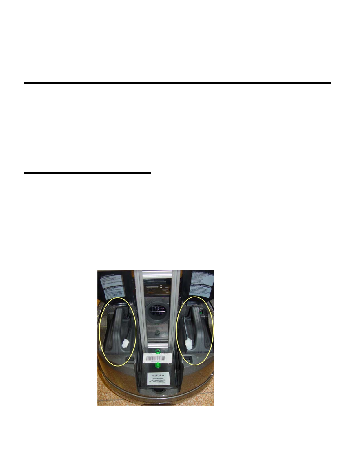
1. Remove and discard the existing batteries in the AGV.
2. Install the two new batteries provided with the installation kit. Be sure that the
battery marked "RIGHT" is installed in the right battery bay, and that the battery
marked "LEFT" is installed in the left battery bay.
Wireless Internet Camera for ER-400
Installation Guide 3 Mounting the Camera
(0601)
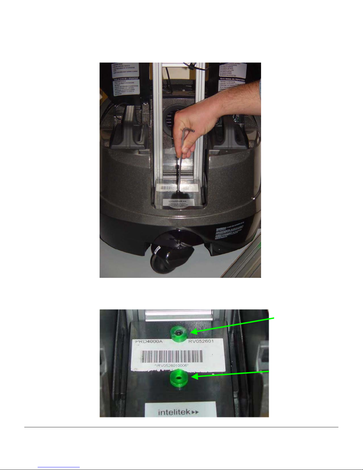
3. Using an Allen wrench, remove and discard the mounting screw as shown. Do not
remove the screw which is closest to the center of the AGV.
4. Install the two green plastic spacers. The spacer with the large hole fits over the
screw which remains, and the spacer with the small hole fits over the hole from
which you just removed a screw in Step 3.
Remaining screw
Hole from removal of
screw
Wireless Internet Camera for ER-400
Installation Guide 4 Mounting the Camera
(0601)

2-pin connector
5. Position the power supply as shown, and secure with a 35 mm x M5 Allen screw.
Tighten with a 4 mm Allen wrench.
Switch is OFF
4-pin
connector
6. Be sure the power switch of the power supply is in the OFF position.
7. Connect the left battery to the power supply using the 2-pin connectors.
8. Connect the right battery to the power supply using the 4-pin connectors.
Wireless Internet Camera for ER-400
Installation Guide 5 Mounting the Camera
(0601)
Attachment of Camera
Mounting Shelf
The Camera Mounting Shelf may be mounted in two different locations on your AGV,
depending on your requirements.
Option A: Low Mount
Intelitek recommends that the Camera Mounting Shelf be mounted in the lower
position. This provides greater stability of the camera's image while the AGV is in
motion, and better protection from damage by foreign objects.
Procedure:
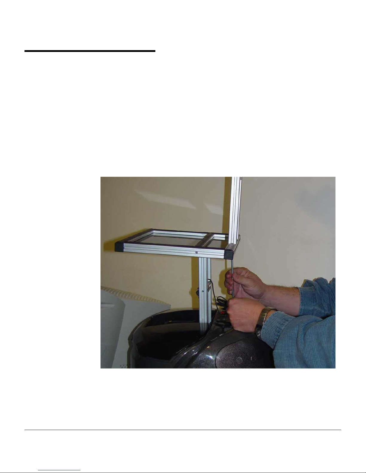
1. Remove and discard the two screws which secure the upper part of the service
stand, as shown here. Be careful to support the upper part so that it does not fall.
Wireless Internet Camera for ER-400
Installation Guide 6 Mounting the Camera
(0601)

2. Install one cable bracket on the right-hand Service Stand Support, as follows:
a. Slide one T-Slot Nut Insert into the rear groove of the Service Stand Support.
b. Slip one cable bracket over the power supply cable which is marked "To
Camera."
c. Insert one 8-mm pan-head Phillips screw through the holes in the cable bracket
and into the threaded hole in the T-Slot Nut Insert. Tighten.
3. Position the Camera Mounting Shelf under the front edge of the Lower Service
Stand Shelf so that it protrudes 13 cm to the front of the AGV. Note that four of
the holes on the bottom side of the Camera Mounting Shelf are beveled. The top
side of the shelf does not have any beveled holes.
Wireless Internet Camera for ER-400
Installation Guide 7 Mounting the Camera
(0601)
 Loading...