

Intelect 225P, 230P User Manual

r
rn
elect'
MODEL
ULTRASOUND
225P/23OP
OPERATOR'S
O
P.lrr.73778
INSTALLATION
O
BEV C
OPERATION
O
MAINTENANGE
O
PARTS
I
y
MANUAL
table
of contents
Description
FOREWORD....
WARRANTY
SAFETY
SPECIF|CAT|ONS
ULTRASOUND
ULTRASOUND
INTELECT
OPERATING
DESCRIPTION
PLOT
ABBREVIATIONS
TROUBLESHOOT|NG....
MAINTENANCE
ULTRASOUND
COMPONENT
PARTS
OF
Ltsr
INFORMATION
INSTRUCTIONS
THERAPY
THERAPY
225PI23OP
PROCEDURE
OF
THE
ULTRASOUND
AND
CALIBRATION
LOCATION,
INDICATIONS
CONTRAINDICATIONS
OPERATING
.
ULTFIASOUND
FIELD
SERVICE
CIRCUIT
.
.
SCHEMATICS
CONTROLS
FIELD
SPATIAL
INSTRUCTIONS
BOARD
DISTRIBUTIONS
.
. . .
. .
.
17,
18,
.
........2
.
,..2
. .....
........4
....5
. ..,
..5
..
. ..
.,..7
.....8
.
. .
..
..
.
..1O
.....,.11
..
....,12
19,
zo, zz,
21,
29
24
25-39
page
3
.6
g
.9
foneword
manuar
This
It contains
information.
in the
aid
tota*y
operating
However,
these
Conponation.
chatranooga
of
free
wannanty
This
punchase
this
lf
materiar
without
is neturned
nepaired
the
has
general
In order
safe
famiriar
it.
owing
specifications
defects
of
Product
and
change
prepared
been
instructions
obtain
to
operation
with
specifications
The
to
of
contrors
the
Chattanooga
be
may
full
corporation
material
in
nemain
shall
product
this
f unction
to
f
ails
workmanship,
period of
within
the
to
Product
a
company
the
to
owners
the
for
operation,
on
maximum
read
unit,
the
the
on
put rortn
Co.f,o."tion'.
any
made
aL
one
(.,company")
workmanship'
and
effect
in
extend=
and
companyi.,n"
or
consumer's
THIS
for
during
thiriy
deirer.
the
WARRANTY
and
safety
efficiency
and
rife
undenstani
and
paner and
in this
time
manuar
policy of
without
Year
warrants
(1)
one
owner
-ny
,o
year.wanranty
one
the
setting
o"y=
isor
company
residence'
the
operators
pnactices'
a.ppricator
the
obrigation
of
maintenance
your
from
manuar
this
that
in effect
were
continuous
wanrantY
rnterect@Model
that
date
the
fnom
year
of
dearer
fnom
or
DOES
the
wiir
the
the
NOT
product
period
reprace
date
dearer
COVEFI:
Intelect@Model
and
Model
comes
improvement'
the
on
of
during
because
which
on
wiil
zzsP/z3oP
thoroughry
with
time
the
at
part of
225Pl23oP
original
the
the
of
repair
on
rhe
the
ship
225Pl23oP'
parts
and
become
and
before
unit
the
publication'
of
changes
chattanooga
("Product"l
consumer'
warnanty
defect
a
Product
this
defective
repracement
to
peniod'
in
Product
to
is
or
anyone
furnished
Replacement
1 .
apProved
Defects
2.
dealen
Any
3.
the
workmanship
failuretoprovidereasonab|eandnecessarymaintenance.
some
above
the
OBTAIN
TO
owner
A
1.
dealer.
A?ET,lOlMemorialDrive,Chattanooga'Tennessee374O5'
The
2.
warranty
This
state
company
liability
or
contained
or
malfunction
warranty
COMPANY
states
limitation
SERVIcE
must
written
to
do
lf the
Product
state.
does
in
in the
parts on
ComPanY
damage
or
approved
an
period if the
if the
or
SHALL
allow
not
do
or
abide
or
claim
connection
must
claim
must
you specific
gives
authorize
not
warranty
labor
service
caused
Company
failure
or
malfunction
NOT
DAMAGES
the
exclusion
the
from
the
by
made
be
is made
returned
be
the
with
shall
agent'
labor
by
service
in the
malfunction
BE
exclusion
not
may
company
following:
within
inr
to
to
legal
person or
any
sale
void
be
by
furnished
agent'
Product
or
failure
or
LIABLE
TO
or
corp"ny,
the
rights,
of
and
FOR
PROPERTY
limitation
apply
the
or
warranty
the
company
and
representative
pnoduct.
this
of
while
failure
to
no
othen
someone
by
in the
ls
it
is not
is caused
INCIDENTAL
BUSINESS.
OR
incidental
of
you'
selling
written
dealer
period to
claim
the
or
you may
Any
effect'
selling
also
company'
the
than
other
possesslc
caused
unreasonable
by
under
should
have
create
to
representative
than
rn
defect
a
by
CONSEOUENTIAL
OR
consequential
or
warranty'
this
company
the
sent
be
dealer
by
other
for
it any
the
company'
the
owner
the
of
material
in
including
use,
damages'
the
or
P'O'
to:
owner'
the
rights
or
which
o'her
agreement
dealer
the
during
I
the
selling
Box
vary
obligation
not
or
and
the
an
so
from
safety
instrucdons
flammable
wABttllluc:
1.
wA.ttrttc:
z.
same
3.
4.Grounding-Makecertainthattheunitise|ectnica||ygroundedbyp|uggingrntoaneIectrica|outlet
5.
6.
.
7
g.
type
Read,
hazards
unit.
wirh
The
understand
a
Intelect
CAUTIOIU:
pnactitioner.
genenator
The
norma||y;especia||ythatthelNTENS|TYcontro|doesproper|yadjusttheintensityofthe
urtrasonic
actually
does
CAUTlOltl:-Use
specified
Explosion
For
rating'
and
associated
ground
ilr,,.,in"f
Model
Federal
shourd
powen
terminate
henein
hazard
continued
practice
and
the
with
recepracle
225PI23OP
restricts
law
routinery
be
output
controls
of
result
may
if
pnotection
safety
the
unrasouno.
iU-grornO
should
this
checked
in a stabre
ultnasonic
or
in
mannen.
adjustments
hazandous
against
and
bb""ru"
not
device
bef
output
fire
operatinginstructi"-1"-'-51"*
oril"tl.
connected
be
sale
to
ore
ntso
power when
performance
or
exposure
presence
the
in
used
of
hazard
"Jt"ty
m"
by,
each
oetlnmine
to
replace
Follow
bo
on
on
to
use
the
ultrasonic
and
ine
any
the
determine
that
timer
of
anesthetics'
fuses
operationar
National
othen
orden
the
neaches
procedures
energy'
only
Electric
device
physician
a
of
,
that
TREATMENT
with
limitations
the
decars
when
controls
all
zero'
other
of
ones
praced
Code'
use'
in
licensed
or
f unction
control
TIME
those
than
and
on
the
the

specifications
-
Frequency
Cycle
Duty
pulse
Pulse
Ultrasonrc
Dunation
Repitition
Output
remporar
Output:
1.
Z.
1.O
-
1OO%
50% t
20%
Powen
Meten
Peak/Averase
continuous
pulse
Duty
-
cycle.
MHz
t
-
5
2
Rate
-
Accuracy-
MHz
1
5%
t
(continuous
10%
1O%
msec
msec
-
1OO
variable
variable
-
MHz
1
signal
model
(Pulse
(Pulse
+
t
Intensitv
model
mode)
(50%
20%
t20%
20%
20%
Hz
t
watt
1
from
2O"/"
watt
ffor
from 1
+
Ftatio-
signal
that
modulated
cycle
duty
cycle
duty
20
to
1O
to
output
any
3,1:
is on
1OO%
pulsed mode)
pulsed model
watts,
watts,
above
}}y;lZi#f
i
long
as
the
by
Intelect
lntelect
1O"/o of
the timer
as
1OO
23OP
225P
maximum)
!:il
ls runnlng'
rectangular
Hz
!I:i:.
wave
with
selected
the
Timer
Applicator:
lnput
Size
Weight
Accuracy:
1 . Less
1O%
2.
1 minute
3.
1. Effective
Maximum
2.
Beam
3.
powen
(Domestic)
(ExPort)
-
12" wide
-
11.5
minutes
o.5
than
settings
for
for
nadiating
beam
-
type
requirements:
12OV + /
Z?Ov
x 5"
lbs.
from 5
settings
non-uniformity
collimating
+
/
high x
for settings
minutes
greater than
area-.8.5
4.O
Hz 1O% 3/4
60
10%
Hz
50
deep
1?"
CM2
CMz
ratio
3/8
(not
less
1O
to
minutes
1O
+
1.5CM2,
+
1.O
-
6.0:1
Amps
AmPs
including
5
than
minutes
Intelect
CMz,
Intelect
handle)
minutes
23OP
225P
(t
ft
18"/")
25"/")
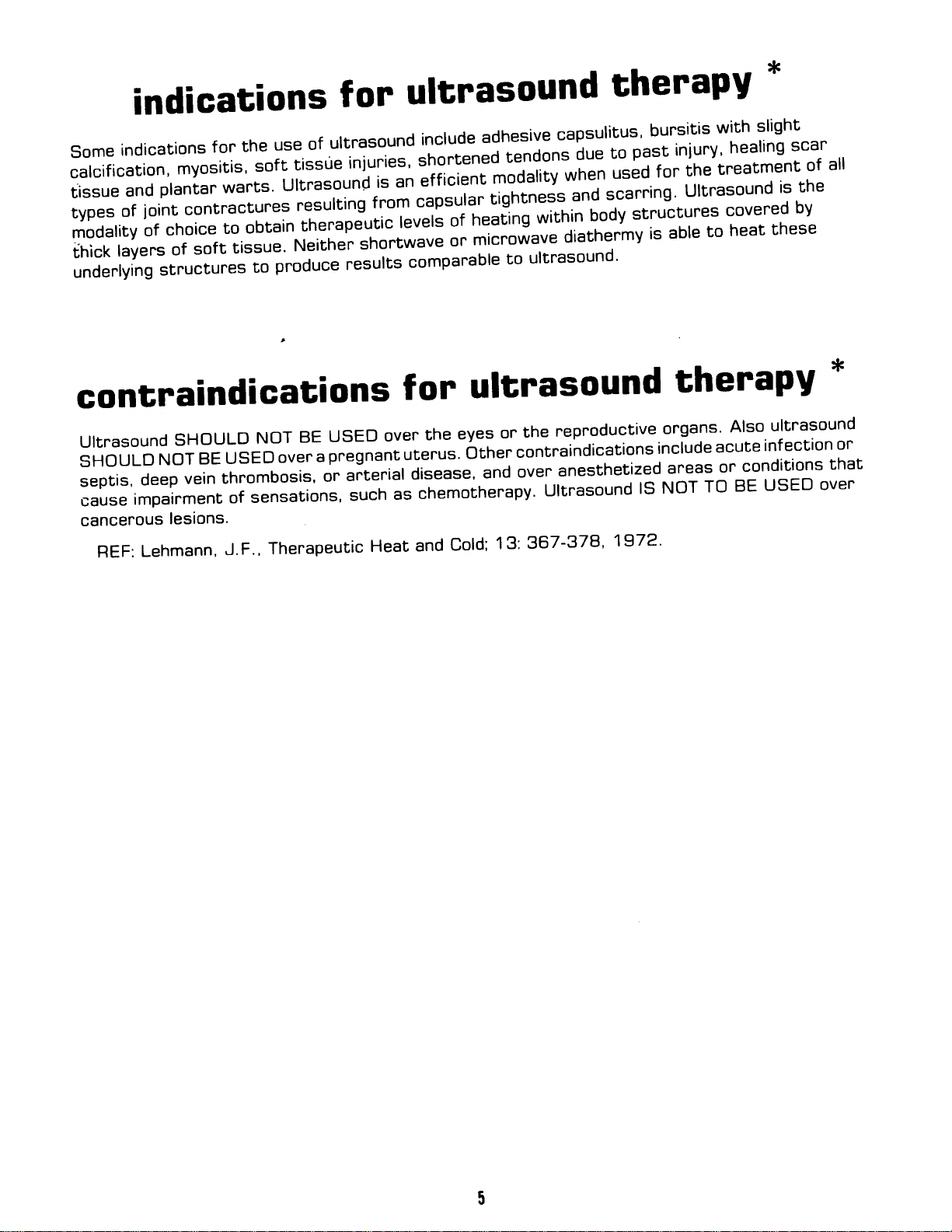
indications
some
carcification,
rissue
rypes
modatiry
thick
underlying
indications
myosrtis,
pranrar
and
of
ioint
choice
of
rayers
of
structures
use
the
for
soft
warrs.
Urrnasound
"onr."ttu.es
obtain
to
sotJii==r".
produce
to
for
urtrasound
of
tissue
resulting
th"."pe,ti"
Neither
i"r".i"",
it;
shortwave
t""'it"
is
contraindications
Urtrasound
sHouLD
septis,
cause
cancerous
REF:
NOT
deep
impairment
lesions'
Lehmann,
sHouLD
USED
BE
thnombosis,
vein
of
J'F.,
usED
BE
Nor
pregnant
a
over
or
sensations,
Therapeutic
over
arterial
such
Heat
ultrasound
incrude
shortened
effici"n,
an
""psular
r"""rl
comparable
fon
the
utenus.
disease,
chemotherapy.
as
and
adhesive
roi"iil;+
tightness
neatinf
ot
microiave
or
ultnasound
eyes
other-
and
Co|d;
tendons
to
on
13:
capsulitus,
due
and
*itnl1
diathermy
ultrasound'
r-eproductive
the
contraindications
anesthetized
over
Ultrasound
367-378,
therapy
bursitis
pas-t
to
for
1"g
scarning'
?od-y-:tl'"tures
1972.
able
is
organs.
incrude
areas
NoT
ls
with
inluny,
healing
treatment
the
Ultrasound
covered
heat
to
therapy
Also
acute
or
TO
{'
slight
scar
of
the
is
by
these
ultrasound
inf ection
conditions
USED
BE
all
'€
or
that
over
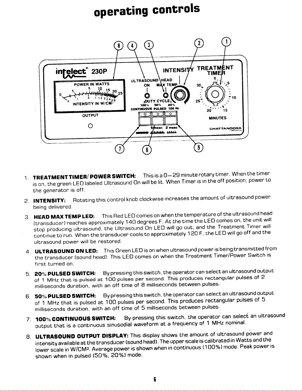
operating
controls
TREATMENT
the
is on,
genenaton
the
INTENSITy:
2.
being
.J.
[tnansducer)
4.
5.
6.
7. 1OO%
g.
delivered.
HEAO
stop
con5inue
ultrasound
uLTRASOUND
the
finst
AO%
of
millisecorrds
50%
of
milliseconds
output
uLTRASOUNO
intensity
lower
shown
MAX
pnoducing
transducer
turned
pULSED
1 MHz
pULSED
MHz that
1
CONTIilUOUS
scale
when
intelect=
/l-
U
TrMER/
green LED
is off.
Rotating
TEMp
reaches
run.
to
power
on.
that
duration,
duration,
is a continuous
that
available
in
LED:
uttrasound,
When
will
ON
[sound
SWITGH:
pulsed
is
SWITGH:
pulsed
is
OUTPUT
at
w/cM2.
pulsed
in
230P
powER
labeled
this
approximately
the
be
LED:
head].
with
with
SWITCH:
transducer
the
Avenage
tsO%,
swrrGH:
Ultrasound
control
Red
This
Ultrasoundbn
the
transducer
restored.
Green
This
This
pressing this
By
putse-s
1OO
at
off time
an
pr
essing
By
putse-s
100
at
time
off
an
sinusodial
DISPLAY:
power
2O%)
,.r*Aor"o\r9lg..^
lrAx
oN
to"h 20
too%
corrtiuous
on
knob
comes
LED
140 degrees
cools
LED
comes
LED
per
of
this
pen
of
pressing this
By
waveform
This
(sound
is shown
mode'
PULaED
is a
This
lit.
be
will
clockwise
when
on
F.
LED
approximately
to
when
is on
when
on
switch,
second.
I milliseconds
switch,
second.
milliseconds
5
at
display
head).
shows
The
when
|
rErrP-
ll,
loo
minute
2g
0-
when
increases
At the
the operator
the
Timer
the
tempenature
the
the
time
go
will
This
This
switch,
a
in
out,
120
ultrasound
Tr"eatment
the
pnoduces
between
operator
produces rectangular
between
the
frequency
amount
the
upper
scale
continuous
notary
is
amount
and
F,
power
can
can
operator
of
is calibnated
timer.
in the
pulses'
pulses'
off
of
the
of
comes
LED
Treatment
the
LED
the
being
is
Timer/Power
select
rectangular
select
1
(100%)
an
an
can
MHz
ultrasound
of
mode.
when
position'
ultrasound
will
ultnasound
ultrasound
nominal.
in
the
power to
ultrasound
the
on'
Timer
go
transmitted
pulses
pulses
select
Watts
and
off
Switch
an
power and
Peak
ttmer
power
head
will
unit
will
the
from
is
output
2
of
output
5
of
ultrasound
the
and
power ts
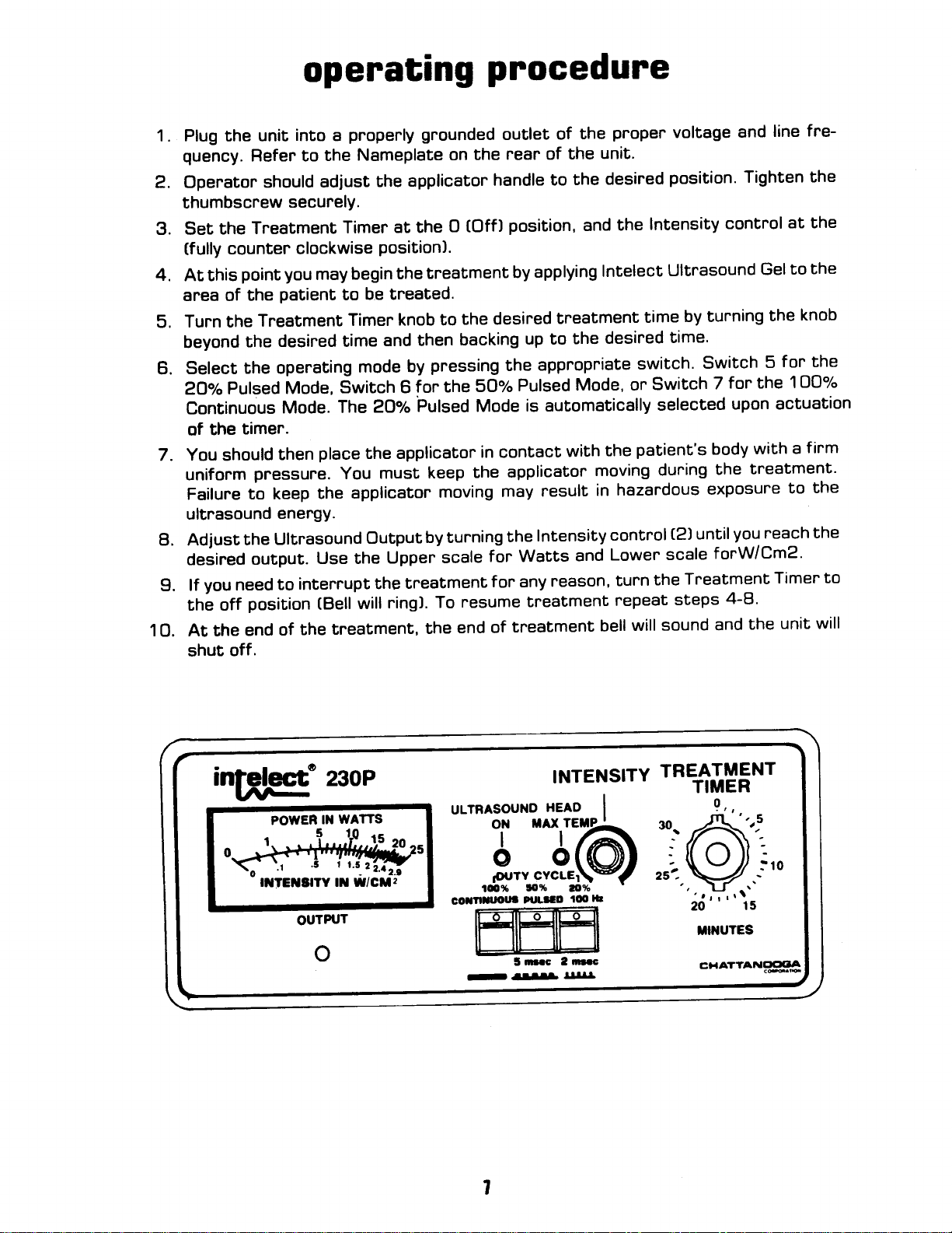
1. Plug
2. Operator
3. Set
4.
5.
6.
7. You should
51 Adjust
g.
1O. At the
the
quency.
thumbscrew
(fully
At this
area of
Turn the
beyond
Select
2oolo
Continuous
of the
uniform
Failure
ultnasound
desired
you
lf
thl off
shut
Flefer to
Tneatment
the
counter
point you
the
Treatment
the
the operating
Pulsed
timer.
pressure.
to keep
the
output.
need
position
end
off.
operating
into
unit
should
securelY.
clockwise
patient
desired time
Mode,
Mode.
then
energy.
Ultrasound
intemupt
to
the
of
properly grounded
a
Nameplate
the
adjust
may
place
the
Use the
(Bell
the
Timer
to
Switch 6
The
You
treatment,
at the
position).
the
begin
be tneated.
Timer knob
and then
mode
2oolo
the applicator
must
applicatop
Output
Upper
the
ring).
will
pnocedure
the
on
applicator
treatment
to
pressing
by
for the
Pulsed Mode
keep
moving
by turning
scale
tneatment
To
the
handle
(Off)
O
the desired
backing
5O%
in contact
the
for Watts
for any
nesume
of
end
the
outlet
rear of
the
applicaton
may
the
of
unit'
the
the
to
position,
applying
by
up to
Pulsed
is automatically
Intensity
treatment
tneatment
and
Intelect
breatment
the
appropriate
Mode, or
with
moving
result
in
and
reason,
bell
proper
desired
the
desined
the
hazardous
control
Lower
tunn
repeat
voltage
position.
lntensity
Ultrasound
by turning
time
time.
switch.
Switch
selected
patient's body
during
t2)
scale
Treatment
the
steps
sound
will
and
Tighten
control
Gel to
the
Switch
7
the
exposune
until
foFW/CmZ.
and
5
the 1OO7"
for
upon actuation
with a
treatment'
you
reach
4-8'
the
fne-
line
the
at the
the
knob
for the
firm
the
to
the
Timer
unit will
to
intelect'
rrr-
U
POWER
ItTEtStTY tt w/CU2
OUTPUT
23oP
WATTS
IN
o
INTENSITY
uLrRAsouND
HEAD
I
TREATMENT
30.
3,,:ir@
ro%
coxflruoul
-- aBl|flr
!lo%
Plrltco
nrc 2
3
ao%
too
nrc
llt
zst-
TIMER
9,,
trINUTES
CHATTANC'CIOA

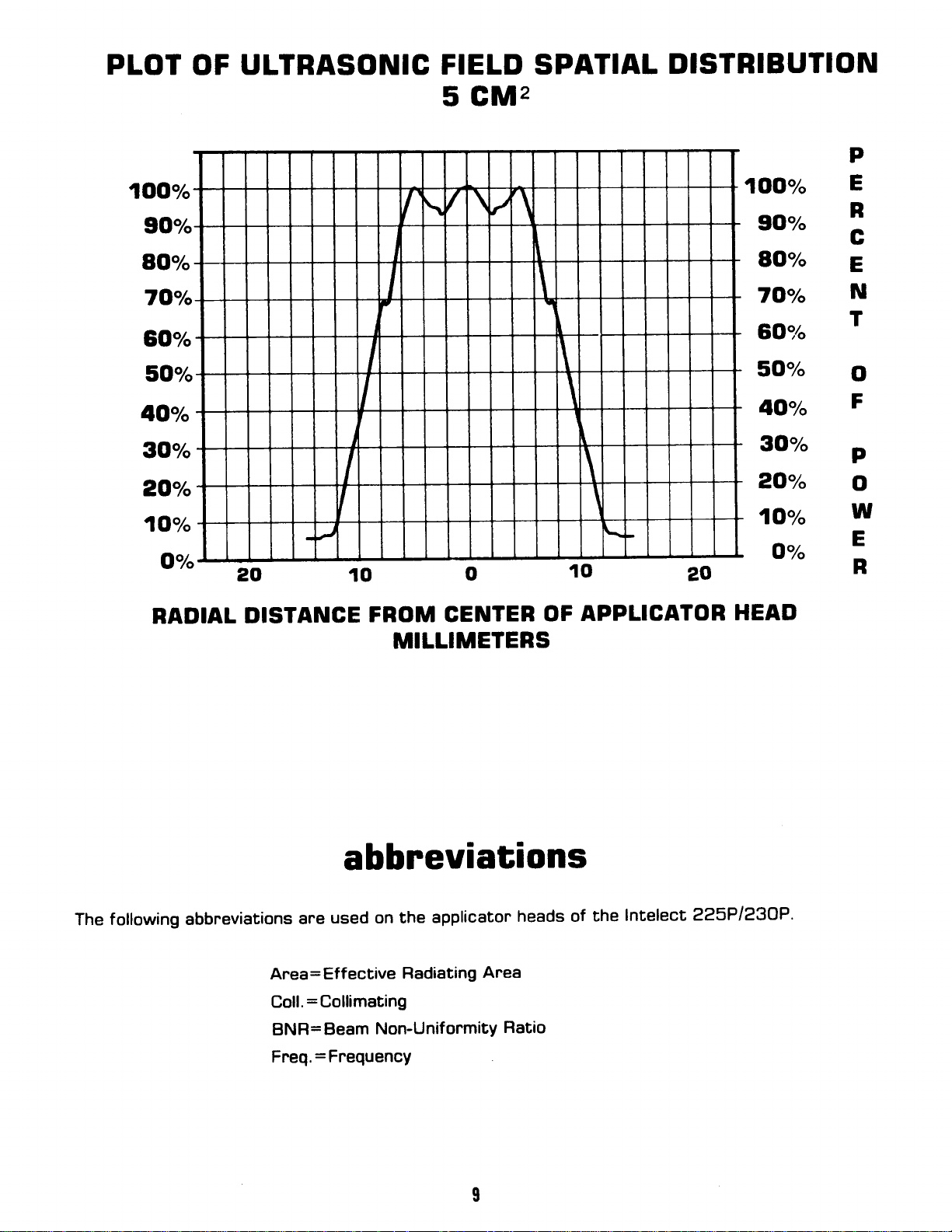
description
of
ultrasonic
field
ultrasonlc
of
measured
generally
infinite
an
of
a
+
1 0
head
and
of
range
sound
takes
DISTRIBUTION
when
the
in
CM2
5
beam
coilimated
spatiar
The
having
millim-eters
energy
The
shapehavingdecneasingintensity",p.og.""sive|yincreasingdistancefromthefaceofthe
transducer.
fierd
This
distilled
rared
the
="r"
ih"
PLOT
distribution
cross-se"tion"r
a
the
from
distribution
dis*ibution
degassed
vortage.
rine
rlEto of
the
as
OF
of
a.s
of
area
30
the
for
deg.
1o
face'
the
CM2
radiated
tnansducer
within
appries
water'at
The
the
ur*asonic
ULTRASONIC
nadiated
the
fierd
cMrlor
radiation
with
and
c.
spatiat
tieto
sound
10
t o
the
is2.4W/CM2
field
emitted
voltage
line
oistriuwion
head'
FIELD
cM2
essentiaily
is
a
sound
cn,i
into
variations
head
maximum'
equivarent
the
the
of
SPATIAL
enengy
point 5
a
at
conic
medium
percent
is essentially
of
of
P
1OOo/"
9O"/"
8O"/"
TOYo
60"/"
RADIAL
20
DISTA]IIGE
to
FROM
o1020
GEilTER
OF
II!LUIIETERS
APPUCATOB
HEAD
10,|,%
9OV"
8O"/"
7O"/"
60o/"
5O"/"
4Oo/"
3O"/"
20o/o
1Oo/"
E
R
c
E
N
T
o
F
P
o
w
E
B
PLOT
OF
ULTRASONIC
FIELD SPATIAL
5 CMz
DISTRIBUTION
P
1OO"/"
90%
BOV"
7Oo/o
6OV"
S,OY"
4O"/"
3O"/"
2O"/"
1O"/"
Oo/o
RADIAL
/ \
I
\
I
-
\
/
\
\
I
1OO"/"
l
201001020
DISTANCE
FROM CENTER
MILLIMETERS
\
I
APPLIGATOR
OF
HEAD
9O"/"
8OV"
7O"/"
6,tJ%
5O"/"
4O"/"
30%
ztJ%
1O"/"
o%
E
B
c
E
N
T
o
F
P
o
W
E
R
following abbreviations
The
abbreviations
used on the
are
Area: Effective
Coll.:Collimating
BNR=
Freq.
Beam
=
Frequency
Radiating
Non-Uniformity
applicator
Area
Ratio
heads of
the
lntelect
225P1?3OP.
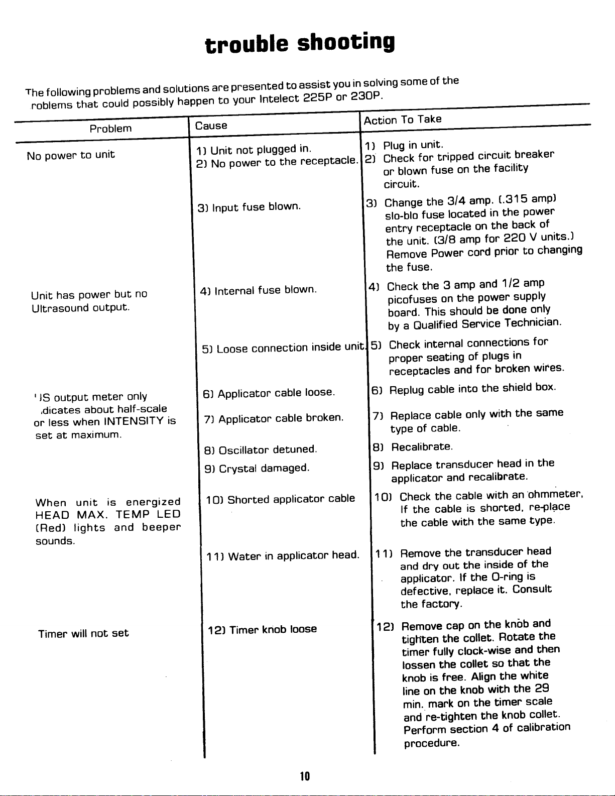
trouble
presented
solutions
The
following
.roblemsthatcouldpossiblyhappentoyourlntelectazsPor23OP'
No
Powen
has
Unit
Ultnasound
rlS
output
,dicates
less
or
at
set
When
HEAD
(Red)
sounds.
problems
Pnoblem
unit
to
Power
outPUt'
meter
about
when
maximum.
lights
INTENSITY
unit
is
MAX.
and
no
but
onlY
half-scale
enengized
TEMP
and
LED
beePer
is
afe
not
Unit
1)
power to
No
2l
fuse
Input
3)
Internal
4l
Loose
5)
Applicator
6)
Applicator
7)
8) Oscillator
Crystal
9)
1O)
1) Water
1
connection
Shorted
Plugged
fuse
damaged.
in
shooting
assist
to
in'
receptacle'
the
blown.
blown.
cable
cable
detuned'
aPPlicator
aPPlicator
you
inside
loose'
broken'
cable
head.
in
uni
solving
Action
1)
2)
3)
$
5)
6)
7)
Plug
ChJck
or
circuit.
Change
slo-blo
entry
ine
Remove
the
Check
picofuses
board.
8)
9)
1O) Check
1 1)
the
of
some
Take
To
unit'
in
tripped
for
on
blown
by
Check
proper seating
necePtacles
Fteplug
Replace
type
Recalibnate.
Replace
applicator
fuse
3/4
the
located
fuse
necePtacle
(3/8
unit.
Power
fuse.
3
the
on
should
This
a Oualified
intennal
and
cable
cable
cable.
of
transducer
and
the
lf the
the
Remove
and
applicator'
defective,
the
cable
dry
with
the
out
cable
factory.
amP
amP
the
Senvice
into
cable
lf
rePlace
circuit
the
amP'
on
cord
and
Power
connections
plugs in
of
for
the
onlY
recalibrate'
is shorted,
the
transducer
inslde
the
the
breaker
facilitY
('315
the
in
back
the
22O
for
prior to
1/2
suPPlY
done
be
Technician'
broken
shield
the
with
head
an'ohmmeter'
wibh
same
of
O-ring
Consult
it'
amP)
Power
of
units')
V
changing
amp
onlY
for
wires'
box'
same
the
in
rePlace
tYPe'
head
the
is
Timer
will
not
set
12)
Timer
knob
loose
l0
121
Remove
tiglften
timer
lossen
knob
line on
cap
the
fullY
the
free.
is
the
mark
min.
r^e-tighten
and
Perform
procedure.
section
kndb
the
on
so
Align
with
timer
the
the
4 of
Rotate
that
the
knob
collet.
clock-wise
collet
knob
on
and
the
then
and
the
white
29
the
scale
collet'
calibration
maintenance
1.
2.
fully maintain
To
recalibrated
products
recalibnations.
component.
following
The
unit:
Power
.1
insulation.
cut
.2 Transducer
frayed
not
Tnansducen
,3
Transducen
.4
material
LEO's.
.5
be
compliance
annually.
returned
is
lt
(See
Section
:;
itehs
and
cord
(applicatorJ
and
(applicator)
(applicator]
the
on
Check
each
lt is recommended
the
to
necommended
also
for Calibration
should
plug.
that
be
check
insulation
stainless
f unction
and
Federal
with
factory or
checked
make
to
Cable.
Handle.
Face.
Check
Check
steel
to see
is intact'
Check
face.
seFuice
Regulation
all Chattanooga
that
authorized
an
replacement
the
Pnocedures'l
monthly
cord
the
make sure
to
make sure
to
that
see
to
is on
LED
at
sure
if
after
least
the
instructions
Title 21
servicing
insure
to
not
is
the
thaL
there
when
CFRI
e1
Corporation
dealer
repair
or
proper
fnayed,
cable
it is
no
is
you
kinked
f lexible,
is
not
build-up
are
this
for
of
operation
or
cracked
of
that
using
must
unit
Ultrasound
repains
majon
any
of this
has torn
f nee of
gel
kinks,
broken'
or
f
oneign
of
f unction.
be
or
or
tl
cAUTroN:
procedure.
An
Calibration
Erectricar
shock
should
calibration
present during
Hazard
periormed
be
is
Oualified
a
by
severar
portions
Senvice
the
of
Technician'
calibration
1.
TEST
.1
EOUIPMENT
power
WV-12O8
line
BEOUIRED
monitor
equivalent
or
(expanded
120VAC
for
scale
voltmeter
for
line'
rated
voltage
line
1o"/d'
t'
VIZ
model
.2Autotransformer,adjustab|efromgoo/oto11o"/"ofrated|inevo|tage,l50wattsor
greater.
U|trasoundPowerMeter,OhmiclnstrumentsMode|UPM-3oorequiva|ent.
.3
equivalent'
Oscilloscope,
.4
Probe,
.5
Probe,current,TextronixP6o2lACcurrentprobeonequiva|ent.
.6
Voltmeter,Digital,,g'l12digits,simpsonModel46lorequivalent'
.7
Probe,
.8
Source
.9
degrees
Counter,
.1O
Stopwatch'
.11
Applicaton
.12
INSTRUMENT
2.
Remove
.1
sidel
each
Remove
.Z
scnew
[one
the
to
g
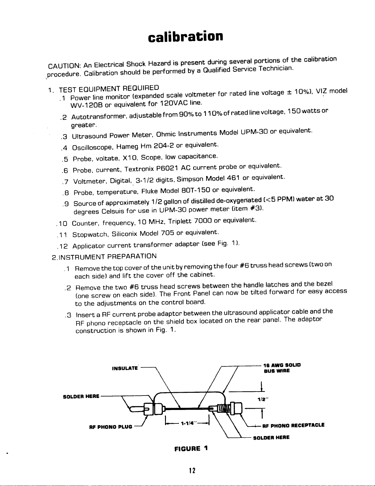
Insert
.
phono neceptacle
RF
construction
Hameg
voltate,
tempenatune,
of
Celsuis
frequency,
the
the
adiustments
RF
a
X1O,
approximately
use
for
1O
Siliconix
current
PREPABATION
top
and
two
on
curnent
is shown
Model
tnansformer
cover
the
lift
#B
side).
each
on
probe adaptor
204-2
Hm
Scope,
Fluke
1/2
in UPM-30
MHz,
of the
coven
truss
the
the
on
Fig'
in
or
capacitance'
low
Model
gallon of
Tniplett
or
7O5
adapter
by
unit
the
off
screws
head
Front
The
control
shield
1.
8OT-15O
distilled
power
equivalent'
removing
cabinet'
Panel
boand'
between
box
or
meter
TOOO
[see
between
can
the
located
equivalent'
de-oxygeriated
(item
#3)'
equivalent'
or
1)'
Fig'
#6
f
our
the
the
now
ultrasound
on
truss
handle
be tilted
rear
the
(<5
PPM)
screws
head
latches
forward
applicator
panel' The
and
waten
for easy
cable and
at
(two
bezel
the
adaptor
30
on
access
the
SOLDER
HEBE
FIGURE
l2
30uD
AWG
1A
WIBE
BUs
1t2"
-T
PHOTIO
NF
SOLDEN
1
NECEPIACLE
HENE
COTTIEGT
TO
'r20
v 60 Hz
(220
POWEn SOUnCE
V 50
HA
10&131
(198-242
VAC
VAC!
FIGUBE 2
3.
TEST
SET-UP
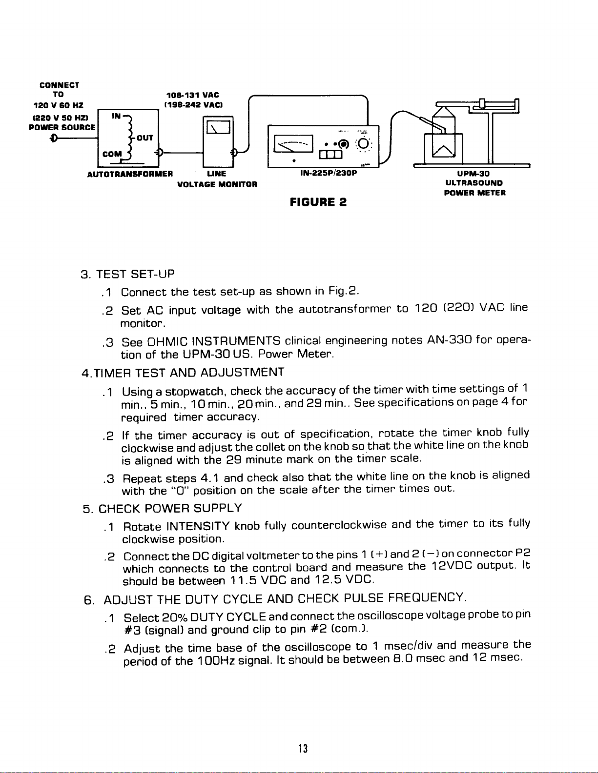
.1 Connect
Set
AC input
.2
montfor.
.g See
of the
tion
4.TIMER
.1
TEST
Using a stopwatch,
min.,-5
required
lf
.Z
the
clockwise
is aligned
.g Repeat
with the
CHECK
5.
POWER
.1 Rotate
clockwise
Connect
.2
which
should
6. ADJUST
.1 Select
(signal)
#3
.Z Adjust
p".ioO
the test
voltage
OHMIC
INSTRUMENTS
UPM-30
AND
min.,
ADJUSTMENT
't
O
timer accuracy.
timer
accuracy
and
with
steps
"o"
position
adjust
the 29
4.1
SUPPLY
INTENSITY
position.
DC
the
connects
be between
THE
DUTY
aO"/"DUTY
and
time
the
of the
I
set-up
as shown
with the
clinical
Powen
us.
check
min.,
ihe
and
knob
the accuracy
and
min.,
2O
is
minute
check
on
of
out
collet
also
scale
the
on
mark
fully counterclockwise
digitalvoltmeten
to the
CYCLE
ground
base of
OOHz
control
11.5
VDC
AND
CYCLE
and
clip
the oscilloscope
signal.
and
connect
pin #2
to
lt
should
Fig.2.
in
autotransfonmer
engineering
Meter.
timen
the
of
specif
min..
29
specification,
knob
the
on
bhat
after
to the
boand
12.5
CHECK
See
so
timen
the
white
the
the
pins
1
measure
and
VDC.
PULSE
rotate
that
timen
t+l
FREOUENCY.
the oscilloscope
(com'1.
msec/div
1
to
between
be
120
to
notes
with
ications
the
white
the
scale'
line on
times
the
and
2 e)
and
the
msec
8.0
€?CJ
AN-33O
settings
time
on
timer
on the
line
knob
the
out.
timer
connectot'
on
12VDC
voltage
and
probe
measure
and
VAC line
fon
opera-
of
page
4 f or
knob
fully
knob
is aligned
fully
its
to
output.
to
the
msec.
12
1
P2
lt
ptn
l3
the
base
scope
Adiust
,3
conErolboard,adjusER6forapu|sewidthofT'9divisions.
.4Se|ect50%DUTYCYCLEandad|usER4ontheconEro|boardforapu|se
width
select
.5
than.5V.
T.CHECK
Connect
.1
rent
Rotate
.2
currenE
wirhin
.3RepeatstepT'2with5oo/odutycyc|eandthenwith2o"/odutycyc|e
selected.
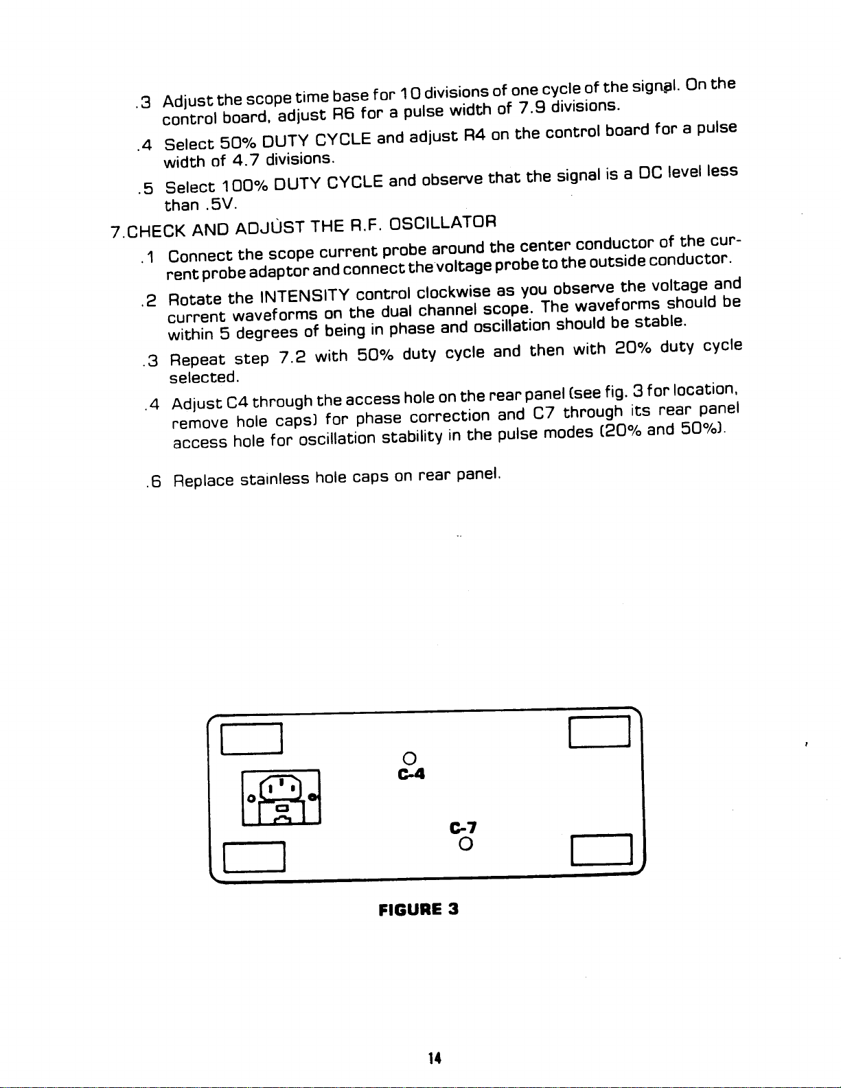
Adiusr
.4
nemove
access
Feplace
.6
Ehe
4.7
of
1OO%DUTY
AND
ADJUST
Ehe
probe adaptor
the
waveforms
i;;;;;;'"i
5
through
c4
hole
hole
stainless
lime
divisions'
CYCLE
THE
SCOpe
INTENSITY
capsl
for
current
and
on
o"i"g
the
for
oscillation
hole
or
observe
and
OSCILLATOR
R.F'
prob.e around
voltage
connect
control
Ehe
access
phase correction
caps
the
clockwise
channet
Jual
i;il;;;nd
hole
stability
near
on
on
in the
divisions
1 O
f
of
that
center
the
probe to
you observe-the
as
scope,
oscillation
rgar
ifre
and
pulse
panel'
the
Th9
palel
c7
cycle
one
of
signal
conductor
outside
the
*?Ytiglts
should
(see
through
modes
DC
is a
stable'
be
3
fig'
its
(2O"/"
sigqal'
the
on
less
level
cur-
the
of
conductor'
voltage
should
f
or
near
and
and
locatton'
panel
50o/o]'
be
n
ffi
r
o
c4
FIGURE
3
t{
ct
o

l\
i
'\.
".
DUTY
CHECK AND
8.
.1 Select
waveform.
.2
Select
adiust
g.
OUTPUT
With
.1
the
Re-apply
.2
Adjust
.3
the
on
Model
10.0
i
Adjust
.4
output
Check
.5
indicated
l-225P
10 0
1.O
2.0
5.O
7.0
ADJUST
DUTY
2oolo
Re-adiust
50%
as
R4
METER
electnical
panel
front
electr.ical
INTENSITY
the
UPM-30
l-225
Watts
meter
the
for this
accuracy
the
on
Meten
W
W
W
W
w
DUTY
the
MODULATED
CYCLE
CYCLE
necessany
CALIBRATION
power
under
power
for the
P
calibnation
model
upNlt-go
and observe
necessany
as
R6
and
obtain
to
femoved,
meter,
the
to
control
model
the
on
output
the
of
at
RF
again
adjust
to
the
on
being
potentiometer,
front
the
Minimum
obsenve
53%
the
align
and
unit
fr"ont
the
used'
panel
meter
power levels
UPM-30
W
.86
1 72w
4.3
W
w
60
8.6
CYCLE
duty
the
obtain
to
the
cycle'
duty
mechanical
meten
the
select
panelto
Model
Watts
20.0
R18,
output
comparing
by
listed
Indication
W
of
cycle
duEy
21"/"
modulated
zeno
pointen
lOOY"
obtain
l-230P
for an
meter'
for each
Maximum
1.14W
2'28
5.7
8.0
11.4
Hz
1OO
the
cycle.
RF
adjustment,
O on
with
cycle'
duty
rated
the
indication
indicatton
its
model'
w
w
w
w
modulaced
wavefonm'
located
meter
the
output
nated
the
of
tne
to
RF
Re-
on
dial'
power
power
l-23OP/Meten
z.OW
W
5.O
10.ow
15.OW
w
20.0
Vary rhe
.6
the
thaf
.7 Select
its rndication
l-225P
50%
Peak
1.0 w
W
2.O
w
s.o
7.O W
w
10.o
l-230P Meter
Peak
2.0 W
W
5.0
10.o w
15.0 W
20.o w
vottage
tine
output
Meter
Power
power
DUTY CYCLE
the
to
POWER
Power
f nom 1 08
remains
and
avg
power
:
avenage
UPM-30
Minimum
172W
4.3
W
8.6
12.9 W
17.2 W
VAC
within
check
(%
W
(1
98VACI
the
the
indication
Cycle)
Duty
UPM-30
Average
Minimum
W
.43
W
.86
W
2.15
W
3.O
4.3 W
UPM-3O
Avenage
Minimum
.86 W
2.15 W
4.3 W
W
6.5
8.6 W
Indication
limits
peak
output
Indicatton
Indication
Maximum
228W
5'7
11'4
17'1
22'8
1 32
tc
listed
meter
the
on
[Power
Power
Maximum
.57
1.14
2.85
4.O
5.7
Power
Maximum
1.14
2.85
5.7
8.5
11.4
W
w
W
W
V
Q
AC
above.
accuracy
UPM-30.
peak]
W
W
W
w
W
W
W
W
W
W
?VACI
by
check
and
compartng
t5
 Loading...