


ADVANCE INFORMATION
COPYRIGHT © INTEL CORPORATION, 1997 November 1997 Order Numbe r: 273108-002
8x931AA/8x931HA
UNIVERSAL SERIAL BUS
PERIPHERAL CONTROLLERS
■ 8x931AA Hubless USB Peripheral
Controller
■ On-chip USB Transceivers
■ On-chip Phase-locked loop
■ FIFO Data Buffers
—Two Pairs of 8-byte Transmit and
Receive FIFOs
—One Pair of 16-byte Transmit and
Receive FIFOs
—Supports Isochronous and
Non-isochronous Data
■ Automatic FIFO Management
■ Three USB Interrupt Vectors
— Endpoint Transmit/Receive Done
—Start of Frame
—Global Suspend/Resume/USB Reset
■ Regulated 3V Output for Root Port
Pullup Resistor
■ On-chip ROM Options
—0 or 8 Kbytes
■ 256 bytes On-chip Data RAM
■ Four Input/Output Ports
■ MCS® 51 UART
■ Three 16-bit Timer/Counters
■ Keyboard Control Interface
■ Four Dedicated LED Driver Outputs
■ 6- or 12-MHz Crystal Operation
—Low Clock Mode (3MHz)
■ 8x931HA Includes all 8x931AA
Features
■ 8x931HA USB Hub has One Internal
Downstream, and Four External
Downstream Ports
—Universal Serial Bus Specification
1.0 Compliant
— Serves as both USB Hub and USB
Embedded Function (Internal Port)
■ USB Hub
—Connectivity Management
—Downstream Device
Connect/Disconnect Detection
—Power Management, Including
Suspend and Resume
—Bus Fault Detection and Recovery
—Full and Low Speed Downstream
Device Support
■ Hub Endpoint Done Interrupt
■ Output Pin for Port Power Switching
■ Input Pin for Overcurrent Detection
■ Hub FIFO Data Buffers
—One Pair of 8-byte Transmit and
Receive FIFOs
—One 1-byte Transmit Register
■ Embedded Function FIFO Data Buffers
—Same as the 8x931AA
■ 12-MHz Crystal Operation
—Low Clock Mode (3MHz)
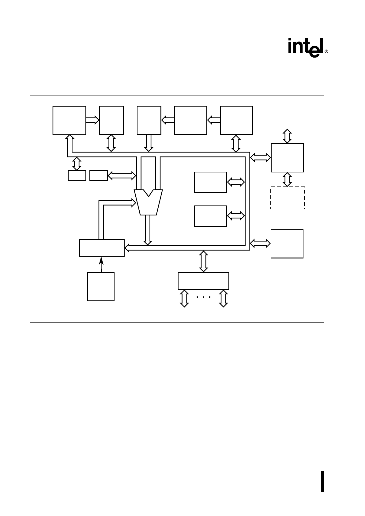
The 8x931AA and 8x931HA USB peripheral controllers are based on the MCS®51 microcontroller. They
consist of standard 8X C5 1Fx peripherals plus a USB module. The 8
x
931HA USB module provides both USB
hub and USB embedded function capabilities. The 8
x
931HA supports USB hub functionality, embedded
function, suspend/resume modes, isochronous/non-isochronous transfers, and is USB rev 1.0 specification
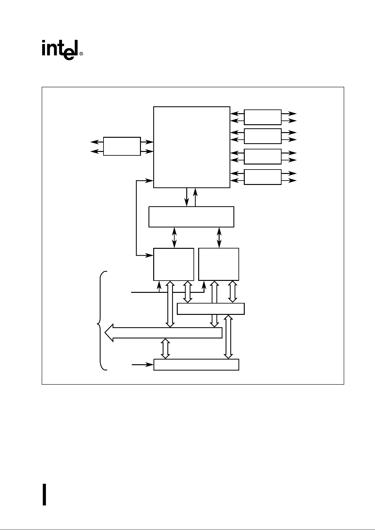
compliant. The USB module contains one internal and 4 external downstream ports and integrates the USB
transceivers, serial bus interface engine (SIE), hub interface unit (HIU), function interface unit (FIU), and
transmit/receive FIFOs. The 8
x
931AA is a hubless USB peripheral controller which contains the same
feature set as the 8
x
931HA hub controller except for the hub module. The 8x931AA/HA uses the standard
instructi on set of the MCS 51 archi tecture.

Information in this document is provided in connection with Intel products. No license, express or implied, by estoppel or oth-
erwise, to any intellectual property rights is granted by this document. Except as provided in Intel’s Terms and Conditions of
Sale for such produc t s, Intel assu m es no liabili ty w hatsoever, and Intel d is c l ai m s any express or implie d warranty, re lating to
sale and/or use of Intel products including liability or warranties relating to fitness for a particular purpose, merchantability, or
infringement of any patent, co py r i ght or othe r intellect ual proper t y ri ght. Intel p r oducts are not intend ed f or use in medical, life
saving, or life sustaining applications.
Intel retains the right to make changes to specifications and product descriptions at any time, without notice.
*Third-party brands and names are the property of their respective owners.
Contact your lo cal I nte l sa les of fi ce or you r dis tri but or to ob tai n the late st spe cif icat i ons an d bef ore pl ac in g your pro duct order.
Copies of documents which have an ordering number and are referenced in this document, or other Intel literature, may be
obtained from:
Intel Corporation
Literature Sales
PO Box 5937
Denver , CO 80217 - 9808
or call 1-800-548-4725
COPYRIGHT © INTEL CORPORATION, 1997

iii
CONTENTS
1.0 About This Document.......................................................................................................... 1
1.1 Additional Information Sources ...................................................................................... 1
1.2 Electronic Information..................................................................................................... 1
1.3 Product Summary........................................................................................................... 2
2.0 Nomenclature Overview ...................................................................................................... 4
3.0 Pinout.................................................................................................................................. 6
3.0.1 8x931HA 68-pin PLCC Package ..................................................................................6
3.0.2 8x931AA 68-pin PLCC Package ..................................................................................7
4.0 Signals .............................................................................................................................. 10
5.0 Electrical Characteristics................................................................................................... 13
5.1 Operating Frequencies................................................................................................. 14
5.2 DC Characteristics........................................................................................................ 15
5.3 Explanation of Timing Symbols.................................................................................... 17
5.4 System Bus AC Characteristics.................................................................................... 18
5.4.1 System Bus Timing Diagrams ....................................................................................19
5.5 AC Characteristics — Synchronous Mode 0................................................................ 21
5.6 External Clock Drive..................................................................................................... 22
5.7 Testing Waveforms ...................................................................................................... 23
6.0 Thermal Characteristics .................................................................................................... 24
7.0 Design Considerations...................................................................................................... 24
7.1 Low Clock Mode Frequency......................................................................................... 24
7.2 Setting RXFFRC Bit Clears Only the Oldest Packet in the FIFO................................. 24
7.3 Series Resistor Requirement for Impedance Matching................................................ 24
7.4 Pullup Resistor Requirement for 8x931AA/HA devices................................................ 24
7.5 Powerdown Mode Cannot Be Invoked Before USB Suspend...................................... 24
7.6 Unused Downstream Ports........................................................................................... 24
7.7 ECAP Usage to Supply 3.0 to 3.6 Volts for 1.5K Ohm Pullup...................................... 24
8.0 8x931AA/HA Errata........................................................................................................... 25
9.0 Datasheet Revision History............................................................................................... 25

8x931AA, 8x931HA USB PERIPHERAL CONTROLLER
iv
Figures
1. 8x931 Functional Block Diagram...... ......... ........ ......... ........ ........ ..........................................2
2. 8x931HA USB Module Block Diagram.................................................................................3
3. Product Nomenclature .........................................................................................................4
4. 8x931HA 68-pin PLCC Package..........................................................................................6
5. 8x931AA 68-pin PLCC Package..........................................................................................7
6. 8x931AA/HA External Program Memory Read..................................................................19
7. 8x931AA/HA External Data Memory Read........................................................................20
8. 8x931AA/HA External Data Memory Write.........................................................................20
9. Serial Port Waveform — Synchronous Mode 0..................................................................21
10. External Clock Drive Waveforms....................... ......... ........ ........ ......... ........ .......................22
11. AC Testing Input, Output Waveforms.................................................................................23
12. Float Waveforms................................................................................................................23
Tables
1. Related Documentation........................................................................................................1
2. Electronic Informatio n ....................................... ......... ........ ........ ..........................................1
3. Description of Product Nomenclature........ ...........................................................................4
5. 8x931AA Proliferation Options.............................................................................................5
4. 8x931HA Proliferation Options.............................................................................................5
6. 68-pin PLCC Pin Assignment...............................................................................................8
7. 68-pin PLCC Signal Assignments Arranged by Functional Category..................................9
8. Signal Description..............................................................................................................10
9. 8x931AA/8x931HA Supply Voltages..................................................................................13
10. 8x931HA Operating Frequency..........................................................................................14
11. 8x931AA Operating Frequencies.......................................................................................14
12. DC Characteristics at Operating Conditions.......................................................................15
13. AC Timing Symbol Definitions...........................................................................................17
14. External Bus Characteristics.............................................. ........ ......... ........ ......... ........ ......18
15. Serial Port Timing — Synchronous Mode 0.......................................................................21
16. External Clock Drive................................................... ........ ........ ......... ...............................22
17. Thermal Characteristics .....................................................................................................24
18. Vcc and Typical ECAP Voltages........................................................................................25
ADVANCE INFORMATION 1
8x931AA, 8x931HA USB PERIPHERAL CONTROLLER
1.0 ABOUT THIS DOCUMENT
This data sheet contains advance information about
Intel’s 8
x
931AA and 8x931HA Universal Serial Bus
peripheral controllers, based on the MCS®51
peripheral controller, which includes a functional
overview, mechanical data, targeted electrical
specifications (simulated), and bus functional
waveforms. A detailed functional description, other
than parametric performance, is published in the
8x931AA, 8x931HA Universal Serial Bus Peripheral
Controller User’s Manual (273102-001).
1.1 Additional Information Sources
Intel documentation is available from your local Intel
Sales Representative or I ntel Literatur e Sales.
Intel Corporation
Literature Sales
PO Box 5937
Denver, CO 80217-9808
or call 1-800-548-4725
1.2 Electronic Information
We offer a variety of technical and product information through the World Wide Web (see Table 2
for URL) and through FaxBack service which is an
on-demand publishing system that sends
documents to your fax machine. You can get
product announcements, change notifications,
product literature, device characteristics, design
recommendations, and quality and reliability information 24 hours a day, 7 days a week. Just dial the
telephone number and respond to the system
prompts.
Table 1. Related Documentation
Table 2. Electronic Information
Document Title Order/Contact
8x931AA, 8x931HA Universal Serial Bus Peripheral
Controller User’s Manual
Intel Order #273102-001
Universal Serial Bus Specification, Rev. 1.0
Intel Order #272904
Document Title Order/Contact
Intel’s World-Wide Web (WWW) Location: http://www.intel.com/design/usb/
Customer Support (US and Canada): 800-628-8686
FaxBack Servi ce:
US and Canada
800-628-2283
Europe
+44(0)793-496646
worldwide
916-356-3105
Application Bulletin Board Service:
up to 14.4-Kbaud line, worldwide
916-356-3600
dedicated 2400-baud line, worldwide
916-356-7209
Europe
+44(0)793-496340
2 ADVANCE INFORMATION
8x931AA, 8x931HA USB PERIPHERAL CONTROLLER
1.3 Product Summary
Figure 1. 8x931 Functional Block Diagram
A4518-01
Upstream
Port
Data
Address
Register
ALU
ROMRAM
B ACC
Program
Counter
Program
Address
Register
USB
Module
Downstream
Ports
Data
Pointer
Stack
Pointer
Instruction
Sequencer
Clock
and
Reset
Parallel
Ports
On-chip
Peripherals
HA only
ADVANCE INFORMATION 3
8x931AA, 8x931HA USB PERIPHERAL CONTROLLER
Figure 2. 8x931HA USB Module Block Diagram
D
P5
D
M5
Transceiver
A5247-01
D
P4
D
M4
D
P3
D
M3
D
P2
D
M0
D
P0
D
M2
Repeater
USB Upstream Port
(Hub Root Port)
USB External
Downstream Ports
Serial Bus Interface Engine
(SIE)
Transceiver
Transceiver
Transceiver
Hub
Interface
Unit
(HIU)
Function
Interface
Unit
(FIU)
Control
Control
FIFOs
Data Bus
To
CPU
Transmit/Receive Bus
Transceiver

4 ADVANCE INFORMATION
8x931AA, 8x931HA USB PERIPHERAL CONTROLLER
2.0 NOMENCLATURE OVERVIEW
Figure 3. Product Nomenclature
Table 3. Description of Product Nomenclature
Parameter Options Description
Temperature and Burn-in no mark Commercial operating temperature range (0
o
C to 70oC) with
Intel standard burn-in
Packaging Op tions N Plastic Leaded Chip Carrier (PLCC)
Program Memory Options 0 Without ROM
3 With ROM
Process and Voltage Inform ation no mark CHMOS
Product Family 931Hx Advanced 8-bi t microcontrol ler architectur e w i th on-chip
Universal Serial Bus Hub and Function capability. Indicates
ROM size, RAM size, and quantity of external down stream
ports (see Table 4).
931Ax Advanced 8-bit microcontroller architecture with on-chip
Univers al Serial Bus Function capability. Indicates ROM
size, RAM size, and quantity of external down st r eam ports
(see Table 5).
Device Speed no mark 6 or 12 MHz crystal (8
x
931AA), 12MHz crystal (8x931HA)
A2815-01
Program Memory Options
XXXXX XXXX8XXX
Packaging Options
Temperature and Burn-in Options
Process Information
Product Family
Device Speed
ADVANCE INFORMATION 5
8x931AA, 8x931HA USB PERIPHERAL CONTROLLER
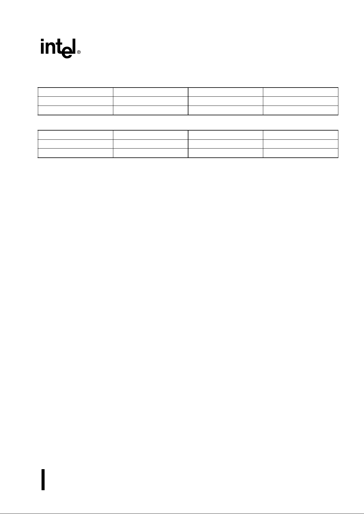
Table 5. 8x931AA Proliferation Options
Table 4. 8
x
931HA Proliferation Options
Part Name ROM Size RAM Size Package
N80931HA 0 256 bytes 68-pin PLCC
N83931HA 8 Kbytes 256 bytes 68-pin PLCC
Part Name ROM Size RAM Size Package
N80931AA 0 256 bytes 68-pin PLCC
N83931AA 8 Kbytes 256 bytes 68-pin PLCC

6 ADVANCE INFORMATION
8x931AA, 8x931HA USB PERIPHERAL CONTROLLER
3.0 PINOUT
3.0.1 8x931HA 68-pin PL C C Package
Figure 4 illustrates a diagram of the 8
x
931HA PLCC package. Tabl e 6 and Table 7 cont ain indexes o f the pin
arrangement. T able 8 contains the signal descri ptions for all pins.
.
Figure 4. 8
x
931HA 68-pin PLCC Package
D
P4
D
M4
D
P5
D
M5
V
CC
D
P0
D
M0
ECAP
V
SS
V
CC
V
SS
D
P3
D
M3
V
SS
D
P2
D
M2
LED0
A8 / P2.0 / KSO8
A9 / P2.1 / KSO9
A10 / P2.2 / KSO10
A11 / P2.3 / KSO11
A12 / P2.4 / KSO12
A13 / P2.5 / KSO13
A14 / P2.6 / KSO14
A15 / P2.7 / KSO15
VSSVCCEA#
ALE
PSEN#
UPWEN#
VSSReserved (NC)
Reserved (NC)
A5340-02
AD7 / P0.7 / KSI7
AD6 / P0.6 / KSI6
AD5 / P0.5 / KSI5
AD4 / P0.4 / KSI4
AD3 / P0.3 / KSI3
AD2 / P0.2 / KSI2
AD1 / P0.1 / KSI1
AD0 / P0.0 / KSI0
V
SS
V
CC
P3.0 / OVRI#
P3.1 / SOF#
P3.2 / INT0#
P3.3 / INT1#
P3.4 / T0 / KSO16
P3.5 / T1 / KSO17
P3.6 / WR# / KSO18
60
59
58
57
56
55
54
53
52
51
50
49
48
47
46
45
44
View of component as
mounted on PC board
8
x
931H
x
10
11
12
13
14
15
16
17
18
19
20
21
22
23
24
25
26
P3.7 / RD# / KSO19
P1.0 / T2 / KSO0
P1.1 / T2EX / KSO1
P1.2 / KSO2
P1.3 / KSO3
P1.4 / KSO4
P1.5 / KSO5
P1.6 / RXD / KSO6
P1.7 / TXD / KSO7
LED3
LED2
XTAL1
XTAL2
AV
CC
RST
PLLSEL
LED1
2728293031323334353637383940414243
987654321
68676665646362
61
Note:
Reserved pins must be left unconnected.

ADVANCE INFORMATION 7
8x931AA, 8x931HA USB PERIPHERAL CONTROLLER
3.0.2 8x931AA 68-pin PLCC Package
Figure 5 illustrates a diagram of the 8
x
931AA PLCC pac kage. Table 6 and Ta ble 7 contain indexes of the pin
arrangement. Table 8 contains the signal descriptions for all pins.
Figure 5. 8
x
931AA 68-pin PLCC Package
Reserved (NC)
Reserved (NC)
Reserved (NC)
Reserved (NC)
V
CC
D
P0
D
M0
ECAP
V
SS
V
CC
V
SS
Reserved (NC)
Reserved (NC)
V
SS
Reserved (NC)
Reserved (NC)
LED0
A8 / P2.0 / KSO8
A9 / P2.1 / KSO9
A10 / P2.2 / KSO10
A11 / P2.3 / KSO11
A12 / P2.4 / KSO12
A13 / P2.5 / KSO13
A14 / P2.6 / KSO14
A15 / P2.7 / KSO15
VSSVCCEA#
ALE
PSEN#
FSSEL
VSSReserved (NC)
Reserved (NC)
A5348-02
AD7 / P0.7 / KSI7
AD6 / P0.6 / KSI6
AD5 / P0.5 / KSI5
AD4 / P0.4 / KSI4
AD3 / P0.3 / KSI3
AD2 / P0.2 / KSI2
AD1 / P0.1 / KSI1
AD0 / P0.0 / KSI0
V
SS
V
CC
P3.0
P3.1 / SOF#
P3.2 / INT0#
P3.3 / INT1#
P3.4 / T0 / KSO16
P3.5 / T1 / KSO17
P3.6 / WR# / KSO18
60
59
58
57
56
55
54
53
52
51
50
49
48
47
46
45
44
View of component as
mounted on PC board
8
x
931A
x
10
11
12
13
14
15
16
17
18
19
20
21
22
23
24
25
26
P3.7 / RD# / KSO19
P1.0 / T2 / KSO0
P1.1 / T2EX / KSO1
P1.2 / KSO2
P1.3 / KSO3
P1.4 / KSO4
P1.5 / KSO5
P1.6 / RXD / KSO6
P1.7 / TXD / KSO7
LED3
LED2
XTAL1
XTAL2
AV
CC
RST
PLLSEL
LED1
2728293031323334353637383940414243
987654321
68676665646362
61
Note:
Reserved pins must be left unconnected.

8 ADVANCE INFORMATION
8x931AA, 8x931HA USB PERIPHERAL CONTROLLER
Table 6. 68-pin PLCC Pin Assignment
Pin Name Pin Name Pin Name
1V
SS
24 P3.4/T0/KSO16 47 V
SS
2 A15/P2.7/KSO15 25 P3.5/T1/KSO17 48 Reserved†/ D
M3
††
3 A14/P2.6/KSO14 26 P3.6/WR#/KSO18 49 Reserved†/ D
P3
††
4 A13/P2.5/KSO13 27 P3.7/RD#/KSO19 50 V
SS
5 A12/P2.4/KSO12 28 P1.0/T2/KSO0 51 V
CC
6 A11/P2.3/KSO11 29 P1.1/T2EX/KSO1 52 V
SS
7 A10/P2.2/KSO10 30 P1.2/KSO2 53 ECAP
8 A9/P2.1/KSO9 31 P1.3/KSO3 54 D
M0
9 A8/P2.0/KSO8 32 P1.4/KSO4 55 D
P0
10 AD7/P0.7/KSI7 33 P1.5/KSO5 56 V
CC
11 AD6/P0.6/KSI6 34 P1.6/KSO6/RXD 57 Reserved†/ D
M5
††
12 AD5/P0.5/KSI5 35 P1.7/KSO7/TXD 58 Reserved†/ D
P5
††
13 AD4/P0.4/KSI4 36 LED3 59 Reserved†/ D
M4
††
14 AD3/P0.3/KSI3 37 LED2 60 Reserved†/ D
P4
††
15 AD2/P0.2 /KSI2 38 XTAL1 61 Reserved (NC )
16 AD1/P0.1 /KSI1 39 XTAL2 62 Reserved (NC )
17 AD0/P0.0/KSI0 40 AV
CC
63 V
SS
18 V
SS
41 RST 64 FSSEL†/ UPWEN#
††
19 V
CC
42 PLLSEL 65 PSEN#
20 P3.0/ OVRI#
††
43 LED1 66 ALE
21 P3.1/SOF# 44 LED0 67 EA#
22 P3.2/INT0# 45 Reserved
†
/ D
M2
††
68 V
CC
23 P3.3/INT1# 46 Reserved†/ D
P2
††
†
Specific to the 8x931AA
††
Specific to the 8x931HA

ADVANCE INFORMATION 9
8x931AA, 8x931HA USB PERIPHERAL CONTROLLER
Table 7. 68-pin PLCC Signal Assignments Arranged by Functional Category
Address & Data Input/Output USB
Name Pin Name Pin Name Pin
A15/P2.7/KSO15 2 P1.0/T2/KSO0 28 PLLSEL 42
A14/P2.6/KSO14 3 P1.1/T2EX/KSO1 29 D
M0
54
A13/P2.5/KSO13 4 P1.2/KSO2 30 D
P0
55
A12/P2.4/KSO12 5 P1.3/KSO3 31 Reserved
†
/ D
M5
††
57
A11/P2.3/KSO11 6 P1.4/KSO4 32 Reserved
†
/ D
P5
††
58
A10/P2.2/KSO10 7 P1.5/KSO5 33 Reserved
†
/ D
M2
††
45
A9/P2.1/KSO9 8 P1.6/KSO6 34 Reserved
†
/ D
P2
††
46
A8/P2.0/KSO8 9 P1.7/KSO7 35 Reserved
†
/ D
M3
††
48
AD7/P0.7/KSI7 10 P3.0/ OVRI#
††
20 Reserved†/ D
P3
††
49
AD6/P0.6/KSI6 11 P3.1/SOF# 21 ECAP 53
AD5/P0.5/KSI5 12 P3.2/INT0# 22 Reserved
†
/ D
M4
††
59
AD4/P0.4/KSI4 13 P3.3/INT1# 23 Reserved
†
/ D
P4
††
60
AD3/P0.3/KSI3 14 P3.4/T0/KSO16 24 FSSEL
†
/UPWEN#
††
64
AD2/P0.2/KSI2 15 P3.5/T1/KSO17 25 OVRI#
††
20
AD1/P0.1/KSI1 16 P3.6/WR#/KSO18 26
AD0/P0.0/KSI0 17 P3.7/RD#/KSO19 27
Processor Control Power & Ground Bus Control & Status
Name Pin Name Pin Name Pin
P3.2/INT0# 22 V
CC
19,51,
56,68
P3.6/WR#/KSO18 26
P3.3/INT1# 23 AV
CC
40 P3.7/RD#/KSO19 27
RST 41
V
SS
1,18,
47,50,
52,63
PSEN# 65
XTAL1 38 ALE 66
XTAL2 39 EA# 67
†
Specific to the 8x931AA
††
Specific to the 8x931HA

10 ADVANCE INFORMATION
8x931AA, 8x931HA USB PERIPHERAL CONTROLLER
4.0 SIGNALS
Table 8. Signal Description (Sheet 1 of 3)
Signal
Name
Type Description
Alternate
Function
A15:8 O Address Lines. Upper byte of external memory address. P2.7:0/KS 08:15
AD7:0 I/O Address/Data Lines. Lower byte of external memory addre ss
multiplexed with data
P0.7:0/KSI0:7
ALE O Address Latch Enable. ALE signals the start of an external
bus cycle and indicates that va l id address information is
available on lines A15:8 and AD7:0. An external latch can use
ALE to demulti pl ex the address from the address/data bus.
—
AV
CC
PWR Analog VCC. A separate VCC input for the phase-locked loop
circuitry.
—
D
M0
, D
P0
I/O USB Port 0. Root port. Upstream port to the h ost PC. DP0 and
D
M0
are the diff erenti al data plus and da ta minus si gnals of USB
port 0. These li nes do not have inter nal pull up resis tors. Pr ovide
an external 1. 5 KΩ pul lup resis tor a t D
P0
so the device indicates
to the host that it is a full-speed device; or provide an external
1.5 KΩ pullup resi st or at D
M0
so the devic e in dic at es to the host
that it is a low-speed device.
NOTE: D
P
0
low AND D
M
0
low signals an SE0 (USB reset),
causing the 8x931 to stay in reset.
—
D
M2
, D
P2
DM3, D
P3
DM4, D
P4
DM5, D
P5
I/O USB External Downstream Por ts 2, 3, 4,5 . These pins are the
differential data plus and data minus lines for the four USB
external dow nstream ports. These lines do not have i nternal
pulldown res is tors . Pro vi de an ex te rnal 15 KΩ pulldown resistor
at each of these pins. See “Design Considerations” on page
24.
—
EA# I External Access. Directs program memory accesses to on-
chip or off-c hi p code memory. For EA# strapped to ground, all
program memory accesses are off-chip. For EA# strapped to
V
CC
, program acces ses on-ch ip ROM if th e address i s within t he
range of the on-c hip ROM; oth erwise the ac cess is off -chip. The
value of EA# is latched at reset. Fo r devices without on-chip
ROM, EA# must be stra pped to ground.
—
ECAP I External Capacitor. Connect a 1 µF or l arger capacitor
between thi s pin and V
SS
to ensure proper operation of the
differential line dri vers. May be used to supply 3.0v to 3.6 v for
1.5K pullup resistor connected to USB Port 0. See “Design
Considerations” on page 24.
—
FSSEL Full Speed Select. Applies to the 8
x
931AA only. If this pin is
high, full speed USB data rate is selected (12Mbps). If pin is
low, low speed USB data rate is selected (1.5 Mbps). Refer to
Tabl e 11 .
—

ADVANCE INFORMATION 11
8x931AA, 8x931HA USB PERIPHERAL CONTROLLER
INT1:0# I External In terrupts 0 and 1. These inputs set the IE1:0
interrupt flags in the TC ON register. Bit s IT1:0 in TCON sel ect
the triggering method: edge-triggered (high-to-low) or level
triggere d (active low). INT 1:0 also serves as external run
control for timer1:0 when selected by GATE1:0# in TCON.
P3.3:2
KSI7:0 I Keyboard Scan Input. Schmitt-trigger inputs with firmware-
enabled internal pullup resistors used for the input side of t he
keyboard scan matrix.
AD7:0/P0.7:0
KSO19
KSO18
KSO17:16
KSO15:8
KSO7:0
O Keyboard Scan Output. Quasi-bidirectional ports with weak
interna l p ullup re sist or s us ed f or the out put si de of t he key board
scan matrix.
P3.7/RD#
P3.6/WR#
P3.5:4/T1:0
A15:8/P2.7:0
P1.7:0
LED3:0 O LED Drivers. Designed to drive LEDs connected directly to
V
CC
. The current each driver is capabl e of sinking is giv en as
V
OL2
in the datasheet.
—
OVRI# I Overcurrent Sense. Sense input to indicate an overcurrent
condition on an external down-stream port. Active low with an
intern al pullup.
P3.0
P0.7:0 I/O Port 0. Eight- bit, open-drain, bidirectional I/O port. Port 0 pins
have Schmitt trigger inputs.
AD7:0/KSI7:0
P1.7:0 I/O Port 1. Eight - bit quasi-bidi rectional I/O port with internal
pullups.
KSO7:0
P2.7:0 I/O Port 2. Eight - bit quasi-bidi rectional I/O port with internal
pullups.
A15:8/KSO15:8
P3.0
P3.1
P3.2
P3.3
P3.4
P3.5
P3.6
P3.7
I/O Port 3. Eight-bit quasi- bidirectional I/O port with internal
pullups.
OVRI#
SOF#
INT0#
INT1#
T0/KSO16
T1/KSO17
WR#/KSO18
RD#/KSO19
PLLSEL I Phase-locked Loop Select. For normal operation using the
8
x
931HA, connect PLLSEL to logic high. PLLSEL = 0 is used
for factory test only. ( See Table 10). For 8
x
931AA operation,
see Table 11.
—
PSEN# O Progra m St o re En a b le . Read signal output . Asserted for read
accesses to external program memory.
—
RD# O Read. Read signal output. Asserted for read accesses to
external data memory.
P3.7/KSO19
RXD I/O Receive Se rial Data. RXD sends and receives data in serial
I/O mode 0 and rec eives data in serial I/O modes 1, 2, and 3.
P1.6
Table 8. Signal Description (Sheet 2 of 3)
Signal
Name
Type Description
Alternate
Function

12 ADVANCE INFORMATION
8x931AA, 8x931HA USB PERIPHERAL CONTROLLER
RST I Reset. Reset input to the chip. Holding this pin high for two
machine cycles while the oscillator is running resets the device.
The port p ins a re d riv en to t hei r re set conditions whe n a volt age
greater th an V
IH1
is applied, whether or not the osci llator is
running. This pin has an internal pulldown resistor which allows
the device to be reset by connecting a capacitor between this
pin and V
CC
.
Asserting RST when the chip is in idle mode or powerdown
mode returns the chip to normal operation.
—
SOF# O Start of Frame. Start of frame pulse. Active low. Asserted for 8
states when frame timer is locked to USB frame timing and
SOF token or artificial SOF is detected.
P3.1
T1:0 I Timer 1:0 External Clock Input. When timer 1: 0 opera te s as a
counter, a falling edge on the T1:0 pin increments the count.
P3.5:4/KSO17:16
T2 I/O Timer 2 Clock Input/Output. For the timer 2 capture mode,
this signal is the external clock input. For the clock-out mode, it
is the timer 2 cloc k output.
P1.0
T2EX I Timer 2 External Input. In timer 2 capture mode, a falling edge
initiates a capture of t he timer 2 registers. In auto-reload mode,
a falling edg e ca uses the ti mer 2 re gist ers t o be relo aded. I n the
up-down counter mode, this signal determines the count
direction: 1 = up, 0 = down.
P1.1
TXD O Transmit Serial Data. TXD outputs the shift clock in serial I/O
mode 0 and transmi ts serial data in s erial I/O modes 1, 2, and
3.
P1.7
UPWEN# O USB Power Enable. A low signal on this pin applies power to
the external downstream ports.
—
V
CC
PWR Supply Voltage. Connect this pin to the +5v supply voltage.
Use a 0.1µf decoupling capacitor for each Vcc pin.
—
V
SS
GND Circuit Ground. Connect this pin to ground. —
WR# O Write. Write signal output to exter nal memory. P3.6/KSO19
XTAL1 I Oscillator Amplifier Input. When implementing the on-chip
oscillator, connect the external crystal or ceramic resonator
across XTAL1 a nd XTAL2. If an external clock sourc e is used,
connect it to this pin.
—
XTAL2 O Oscillator Amplifier Output. When implementing the on-c hip
oscillator, connect the external crystal or ceramic resonator
across XTAL1 a nd XTAL2. If an external oscill ator is used,
leave XTAL2 unconnected.
—
Table 8. Signal Description (Sheet 3 of 3)
Signal
Name
Type Description
Alternate
Function

ADVANCE INFORMATION 13
8x931AA, 8x931HA USB PERIPHERAL CONTROLLER
5.0 ELECTRICAL CHARACTERISTICS
ABSOLUTE MAXIMUM RATINGS
†
Ambient Temperature Under Bias................... –40°C to +85°C
Storage Temperature .................................. –65°C to +150°C
Voltage on Any Pins to V
SS
.............................–0.5 V to +6.5 V
I
OL
per I/O Pin.................................................................15 mA
Power Dissipation (1)..................................................... 1.5 W
OPERATING CONDITIONS
†
TA (Ambient Temperature Under Bias):
Commercial........................................................-0°C to +70°C
V
CC
(Digital Supply Voltage) .......................... 4.40 V to 5.25 V
V
SS
...................................................................................... 0 V
AV
CC
(Analog Supply Voltage) ...................... 4.40 V to 5.25 V
F
OSC
............. ....................................... ..... ................... . 12 MHz
NOTE:
1. Maximum power dissipation is based on package
heat-transfer limitations, not device power
consumpti on.
NOTICE: This document contains information on
products in t he sampling and initial production
phases of development. The speci fications are
subject to change without notice.Verify with your
local Int el sales office that you have the latest
datasheet before finalizing a design.
†
WARNING: Stressing the device beyond the
“Absolute Maximum Ratings” may cause
permanent damage. These are stress ratin gs
only. Operation beyond the “Operating
Conditions” is not recommended and extended
exposure beyond the “Operating Conditions”
may affect device
reliability.
Table 9. 8x931AA/8x931HA Supply Voltages
Parameter Condition Symbol Min Ma x
Supply Voltage 8
x
931HA Vcc/Vbus 4.40V 5.25V
8
x
931AA Vcc/ Vbus 4.15V
†
5.25V
†
For bus- powered dev i c e, voltage dr oo p during hot pl u g m ay cause the sup ply voltage to drop
to 4V worst case. The functionality of the device is supported at this voltage.

14 ADVANCE INFORMATION
8x931AA, 8x931HA USB PERIPHERAL CONTROLLER
5.1 Operating Frequencies
.
Table 10. 8x931HA Operating Frequency
PLLSEL
XTAL1
Frequency
(F
OSC
)
USB Rate
(1)
Internal
Frequency
(F
CLK
)
(2)
XTAL1
Clocks per
State
(T
OSC
/state)
(3)
Comments
0 (4) –––––
1 12 MHz 12 Mbps
(Full Speed)
6 MHz (3) 2 PLL On
NOTES:
1. The sampling rate is 4 times the USB rate.
2. The internal frequ ency, F
CLK
= 1/T
CLK
, is the clock signal dis tribut ed to th e CPU and the
on-chip per ipherals,
3. Following device reset, the CPU and on-chip pe ri pherals operate in l ow-clock mode
(F
CLK
= 3 MHz) until the LC bit in the PCON register is cleared. In low clock mode,
there are four T
OSC
periods per state. Low-cloc k mode does not affect the USB rate.
4. PLLSEL = 0 is used during factory test only.
Table 11. 8
x
931AA Operating Frequencies
PLLSEL
Pin
FSSEL
Pin
LC Bit
(1)
XTAL1
Frequency
(MHz)
USB Rate
(FS/LS)
(2)
Core
Frequency
F
CLK
(Mhz)
Comment
000 6 LS 3 PLL Off
001 6 LS 3 PLL Off
1 0 0 12 LS 6 PLL Off
1 0 1 12 LS 3 PLL Off
1 1 0 12 FS 6 PLL On
1 1 1 12 FS 3 PLL On
NOTES:
1. Reset and pow er up routine s s e t the LC bit in PCON to put the 8
x
931AA in low-clock mode (core
frequency = 3 MHz) for lower I
CC
prior to device enumeration. Following completion of device
enumer a ti on, firmware shoul d clear the LC bit to exit the lo w - cl ock mode. Th e user may swi tc h th e
core frequency back and forth at any time, as needed.
2. USB rates: Low speed = 1.5 Mbps; Full speed = 12 Mbps. The USB s ample rate is 4X the USB rate.

ADVANCE INFORMATION 15
8x931AA, 8x931HA USB PERIPHERAL CONTROLLER
5.2 DC Characteristics
Table 12. DC Characteristics at Operating Conditions
Symbol Parame ter Min
Typical
(1)
Max Units Te st Conditions
V
IL
Input Low Vo ltage
(except EA #)
–0.5 0.2 V
CC
– 0.1 V
V
IL1
Input Low Vo ltage
(EA#)
0 0.2 V
CC
– 0.3 V
V
IH
Input High Voltage
(except XTAL1, RST)
0.2 V
CC
+ 0.9 V
CC
+ 0.5 V
V
IH1
Input High Voltage
(XTAL1, RST)
0.7 V
CC
V
CC
+ 0.5 V
V
OL
Output Low Voltage
(port 1, 2, 3)
(2)
0.3
0.45
1.0
VI
OL
= 100 µA
I
OL
= 1.6 mA
I
OL
= 3.5 mA
V
OL1
Output Low Voltage
(port 0, ALE, PSEN#,
SOF#)
(2)
0.3
0.45
1.0
VI
OL
= 200 µA
I
OL
= 3.2 mA
I
OL
= 7.0 mA
V
OL2
Output Low Voltage
(LED 0, 1, 2, 3 )
2.0
3.0
VIOL = 6 mA
I
OL
= 22 mA
V
OH
Output High Voltage
(port 1, 2, 3, ALE,
PSEN#, SO F#)
(3)
V
CC
– 0.3
V
CC
– 0.7
V
CC
– 1.5
VI
OH
= –10 µA
I
OH
= –30 µA
I
OH
= –60 µA
V
OH1
Output High Voltage
(port 0 in external
address spac e)
(3)
V
CC
– 0.3
V
CC
– 0.7
V
CC
– 1.5
VI
OH
= –200 µA
I
OH
= –3.2 mA
I
OH
= –7.0 mA
I
IL
Logical 0 I nput
Current
(port 1, 2,3)
–50 µA V
IN
= 0.45 V
I
LI
Input Leak age Current
(port 0)
±10 µA VIN = VIL or V
IH
NOTE:
1. Typical values are obtained using V
CC
= 5.0V, TA = 25°C and are not guaranteed.
2. Capacitiv e l oading on ports 0 and 2 may cause spurious noise pulses above 0. 4 V on the low-level
outputs of ALE and ports 1 , 2 and 3. The noise is due to external bus capacitance discharging into the
port 0 and port 2 pins when these pins change from 1 to 0. In applications where capacitive loading
exceeds 100 pF, the noise pulses on these signals may exceed 0. 8 V. It may be desirable to qualify
ALE or other signals with a Schmitt trigger or CMOS-l evel input logic.
3. Capacitiv e l oading on ports 0 and 2 ca uses the V
OH
on ALE and PSEN t o drop below the VCC
specification when the ad dress lines are stabilizing.

16 ADVANCE INFORMATION
8x931AA, 8x931HA USB PERIPHERAL CONTROLLER
I
TL
Logical 1-to-0
Transiti on C urrent
(Port 1, 2,3)
–650 µA V
IN
= 2.0 V
R
RST
RST Pulldown
Resistor
40 100 KΩ
C
IO
Pin Capacitance 10 pF F
OSC
= 12 MHz
T
A
= 25°C
I
PD
Powerdown Current
USB suspend
145 175
µA
I
DL
Idle Mode ICC 40 mA F
CLK
=6 MHz
30 F
CLK
=3 MHz
I
CC
Active ICC 70 mA
F
CLK
= 6 MHz
50 F
CLK
= 3MHz
U
ZDRV
USB Drivers Output 10 25 KΩ
Table 12. DC Characteristics at Operating Conditions (Continued)
Symbol Parameter Min
Typical
(1)
Max Units Test Conditions
NOTE:
1. Typical values are obtained using V
CC
= 5.0V, TA = 25°C and are not guaranteed.
2. Capacitiv e l oading on ports 0 and 2 may cause spurious nois e pulses above 0.4 V on the low-level
outputs of ALE and ports 1, 2 and 3. The noise i s due to external bus capacitanc e discharging into the
port 0 and port 2 pins when these pins change from 1 to 0. In appl i cations where ca pacitive loading
exceeds 100 pF, the noise puls es on these signa ls may exceed 0.8 V. It may be desirable to qualify
ALE or other signals with a Schmitt trigger or CMOS-level input logic.
3. Capacitiv e loading on ports 0 and 2 causes the V
OH
on ALE and PSEN to drop below the VCC
specification when the address lines are stabilizing.

ADVANCE INFORMATION 17
8x931AA, 8x931HA USB PERIPHERAL CONTROLLER
5.3 Explanation of Timing Symbols
Table 13 defines the timing symbol s used in Tables 14 through 16 and the associat ed timing diagrams. They
have the form T
XXYY
, where the character pai r s represen t a sign al and it s condi tio n. Timing symbols repr es ent
the time be tw een two signal / condition po ints.
Table 13. AC Timing Symbol Definitions
Symbol Definition
A Address: A15:8, A7:0
C External Clock (XTAL1)
D Data In : D7:0
L ALE: Address Latch Enable
P Program Store Enable (PSEN#)
Q Data Out: D7:0
R Read: RD#
W Write: WR#
Character Condition
H High
LLow
V Valid, Setup
X No Longer Valid, Hold
Z Floating (low impedance)

18 ADVANCE INFORMATION
8x931AA, 8x931HA USB PERIPHERAL CONTROLLER
5.4 System Bus AC Characteristics
Test Condit ions: F
OSC
= 12 MHz. Rise and fa ll time s = 10 ns. Ca pacit ive l oa ding on ALE, PS EN#, and port P0
= 100 pF. Capacit i ve loading on all other outputs = 80 pF.
Table 14. External Bus Characteristics
Symbol Parameter F
OSC
= 12 MHz,
F
CLK
= 6 MHz
Variable F
CLK
Units
Min Max Min Max
F
OSC
XTAL1 Frequency 12 ± 0.25% MHz
T
CLK
1/F
CLK
= 1/CPU Fre-
quency
166.67 (Typi cal) ns
T
LHLL
ALE Pulse W i dth 127 T
CLK
– 40 ns
T
AVLL
Address Valid to ALE Low 43 0.5T
CLK
– 40 ns
T
LLAX
Address Hold after ALE
Low
53 0.5T
CLK
– 30 ns
T
PLAZ
PSEN# Low to Address
Float
10 10 ns
T
LLIV
ALE Low to Instruction In
Valid
259 2T
CLK
– 75 ns
T
LLPL
ALE Low to PSEN# Low 53 0.5T
CLK
– 30 ns
T
PLPH
PSEN# Pulse Width 205 1.5T
CLK
– 45 ns
T
PLIV
PSEN# Low to Ins tructi on
In Valid
77 T
CLK
– 90 ns
T
PHIX
Instruction Hold after
PSEN# High
00 ns
T
PHIZ
Instruction Float after
PSEN# High
63 0.5T
CLK
– 20 ns
T
AVIV
Address Valid to Instruc-
tion Valid
312 2.5T
CLK
– 105 n s
T
LLRL, TLLWL
ALE Low to RD# or WR#
Low
200 300 1.5T
CLK
– 50 1.5T
CLK
+ 50 ns
T
RLRH,
T
WLWH
RD# and WR# Pulse
Width
400 3T
CLK
– 100 ns
T
LLDV
ALE Low to Data In Valid 578 4T
CLK
– 90 ns
T
RLDV
RD# Low to Data In Valid 322 2.5T
CLK
– 95 ns
T
RLAZ
RD# Low to Address Float 0 0 ns
T
RHDX
Data Hold After RD# High 0 0 ns
T
RHDz
Data Float After RD# High 23 0.5T
CLK
– 60 ns
T
AVRL
, T
AVWL
Address Valid to RD# or
WR# Low
244 2T
CLK
– 90 ns

ADVANCE INFORMATION 19
8x931AA, 8x931HA USB PERIPHERAL CONTROLLER
5.4.1 System Bu s T iming Dia g ra ms
Figure 6. 8
x
931AA/HA External Program Memory Read
T
AVDV
Address Valid to Data In
Valid
661 4.5T
CLK
– 90 ns
T
RHLH
, T
WHLH
RD# or WR# High to ALE
High
43 123 0.5T
CLK
– 40 0.5 T
CLK
+ 40 ns
T
QVWX
Data Valid to WR# Transi-
tion
48 0.5T
CLK
– 35 ns
T
QVWH
Data Valid to WR# High 514 3.5T
CLK
– 70 ns
T
WHQX
Data Hold After WR# High 43 0.5T
CLK
– 40 ns
Table 14. External Bus Characteristics (Continued)
Symbol Parameter F
OSC
= 12 MHz,
F
CLK
= 6 MHz
Variable F
CLK
Units
Min Max Min Max
ALE
PSEN#
Port 0
Port 2
A5280-02
INSTR INA7:0
A15:8A15:8
T
LHLL
A7:0
T
AVIV
T
AVLL
T
LLPL
T
PLPH
T
LLIV
T
PLAZ
T
PLIV
T
LLAX
T
PHIZ
T
PHIX

20 ADVANCE INFORMATION
8x931AA, 8x931HA USB PERIPHERAL CONTROLLER
Figure 7. 8x931AA/HA External Data Memory Read
Figure 8. 8
x
931AA/HA External Data Memory Write
ALE
RD#
PSEN#
Port 0
Port 2
A5275-02
T
RHLH
Data InA7:0 from RI or DPL
A15:8 from PCHP2.7:0 or A15:8 from DPH
T
LHLL
T
LLRL
T
LLDV
T
RLRH
T
AVLL
T
RLDV
T
LLAX
A7:0 from PCL Inst. In
T
RHDZ
T
RLAZ
T
RHDX
T
AVRL
T
AVDV
ALE
WR#
PSEN#
Port 0
Port 2
A5276-01
T
WHLH
Data OutA7:0 from RI or DPL
A15:8 from PCHP2.7:0 or A15:8 from DPH
T
LHLL
T
LLWL
T
WLWH
T
AVLL
T
QVWX
T
LLAX
A7:0 from PCL Inst. In
T
WHQX
T
AVWL
T
QVWH

ADVANCE INFORMATION 21
8x931AA, 8x931HA USB PERIPHERAL CONTROLLER
5.5 AC Characteristics — Synchronous Mode 0
Figure 9. Serial Port Waveform — Synchronous Mode 0
Table 15. Serial Port Timing — Synchronous Mode 0
Symbol Parameter Min Max Units
T
XLXL
Serial Port Clock Cycle Time 12 T
OSC
ns
T
QVXH
Output Data Setup to Clock Rising Edge 10 T
OSC
– 133 ns
T
XHQX
Output Data Hold after Clock Rising Edge 2 T
OSC
– 50 ns
T
XHDX
Input Data Hold after Clock Rising Edge 0 ns
T
XHDV
Clock Rising Edge to Input Data Valid 10 T
OSC
– 133 ns
Valid
Valid
Valid Valid
Valid Valid
Valid
Valid
RXD
(In)
RXD
(Out)
TXD
01 2
3
4
5
6
7
T
QVXH
T
XLXL
T
XHDX
T
XHQX
T
XHDV
A2592-02
Set TI
†
Set RI
†
†
TI and RI are set during S1P1 of the peripheral cycle following the shift of the eighth bit.

22 ADVANCE INFORMATION
8x931AA, 8x931HA USB PERIPHERAL CONTROLLER
5.6 External Clock Drive
Figure 10. External Clock Drive Waveforms
Table 16. External Clock Drive
Symbol Parameter Min Max Units
1/T
OSC
Oscillat or Frequency (F
OSC
)612MHz
T
CHCX
High Time 20 ns
T
CLCX
Low Time 20 ns
T
CLCH
Rise Time 20 ns
T
CHCL
Fall Time 20 ns
0.7 VCC
A4119-01
0.45 V
VCC – 0.5
0.2 V
CC
– 0.1
T
CHCL
T
CLCX
T
CLCL
T
CLCH
T
CHCX

ADVANCE INFORMATION 23
8x931AA, 8x931HA USB PERIPHERAL CONTROLLER
5.7 Testing Waveforms
Figure 11. AC Testing Input, Output Waveforms
Figure 12. Float Waveforms
AC inputs during testing are driven at V
CC
– 0.5V for a logic 1
and 0.45 V for a logic 0. Timing measurements are made at
0.45 V
Inputs
Outputs
A4118-01
V
IH
MIN
V
OL
MAX
V
CC
– 0.5
0.2 V
CC
+ 0.9
0.2 V
CC
– 0.1
a min of V
IH
for a logic 1 and V
OL
for a logic 0.
V
LOAD
+ 0.1 V
V
LOAD
– 0.1 V
Timing Reference
Points
V
LOAD
V
OH
– 0.1 V
V
OL
+ 0.1 V
For timing purposes, a port pin is no longer floating when a
100 mV change from load voltage occurs and begins to float
when a 100 mV change from the loading V
OH/VOL
level occurs
with I
OL
/
I
OH
= ± 20 mA.
A4117-01

24 ADVANCE INFORMATION
8x931AA, 8x931HA USB PERIPHERAL CONTROLLER
6.0 THERMAL CHARACTERISTICS
The microcontroller operates over the commercial
temperature range from 0
o
C to 70oC. All thermal
impedance data (see Table 17) is approximate for
static air conditions at 1 watt of power dissipation.
Values change depending on operating conditions
and application requirements. The Intel
Packaging
Handbook
(order numbe r 240800) describes Intel’s
thermal impedance test methodology. The
Components Quality and Reliability Handbook
(order number 210997) provides quality and
reliability information.
7.0 DESIGN CONSIDERATIONS
7.1 Low Clock Mode Frequency
During low clock mode, the internal clock F
CLK
distributed to the CPU and peripherals is 3 MHz.
Peripheral timing and external bus accesses
(including instruction fetch and data read/write) are
affected. Refer to Table 10 and Table 11 for clock
rates.
7.2 Setting RXFFRC Bit Clears Only
the Oldest Packet in the FIFO
If the receive FIFO is set as a dual packet mode,
then it can receive two packets. Setti ng RXFFRC (in
RXCON registers) to indicate FIFO Read Complete
will not flush the entire FI FO; it will flush only t he
oldest packet. The read marker will be advanced to
the locati on of the read pointer.
7.3 Series Resistor Requirem ent for
Impedance Matching
Per USB rev. 1.0 specification (page 111, section
7.1.1.1), the impedance of the differential driver
must be between 29Ω and 44Ω. To match the cable
impedance, a series resistor of 27Ω to 33Ω should
be connected to each USB line; i.e., on D
P0
and on
D
M0
. If the USB line is improperly terminated or not
matched, then signal fidelity will suffer. This
condition can be seen on the oscilloscopes as
excessive ov ersho ot and unders ho ot. Thi s c ondi tion
can potentially introduce bi t errors.
7.4 Pullup Resistor Requirement
for 8
x
931AA/HA devices
The USB specification requires a pullup resistor to
allow the host to identify which devices are low
speed and which are full speed in order to communicate at the appropriate data rate. For 8
x
931HA
hub devices (12 Mbps), use a 1.5KΩ pullup resistor
(to 3.0 V – 3.6 V; may use the ECAP pin.) on the
D
P0
line. 8x931AA devices can be either full speed
or low speed; ad d a 1.5KΩ pullup to the appropriate
USB line.
7.5 Powerdown Mode Cannot Be
Invoked Before USB Suspend
If the 8x931AA/HA is put into powerdown mode
before receiving a USB suspend signal from the
host, then a USB resume will not properly wake up
the 8
x
931AA/HA fr om powerdown mode.
7.6 Unused Downstream Ports
If the USB downstream ports are not used, it is still
required that the two data lines be pulled low
externally (similar to a disconnect) so that the inputs
are not floating. This will eliminate the possibility of
induced system noise. All USB data lines require
15KΩ external pulldown resistors. Do not leave
unused port(s) disconnect ed.
7.7 ECAP Usage to Supply 3.0 to 3.6
Volts for 1.5K Ohm Pullup
For a self-powered or bus-powered device, when
the voltage at the V
CC
pins are at 5.25v, the voltage
at ECAP pin will be at approximately 3.6v. If the V
CC
pin is at 4.65v [Min, Vbus Powered (host or hub)
Port specification], the voltage at the ECAP pin will
be at approximately 3.2v (refer to Table 18 below).
The capability for this pin to su pply the 3.0v to 3.6v
voltage to the 1.5KΩ USB pullup terminator
depends upon t he V
CC
voltage level.
Table 17. Thermal Characterist ics
Package Type θ
JA
†
θ
JC
†
68-pin PLCC N/A N/A
†
Data unavailable at time of publication.

ADVANCE INFORMATION 25
8x931AA, 8x931HA USB PERIPHERAL CONTROLLER
For a bus-powered device that is connected to a
bus-powered hub, when the voltage at the Vcc pins
(in the bus-powered devices) are at 4.28v, the
voltage at ECAP pin will be at approximately 3.0v. If
the Vcc voltage drops below 4.28v, the ECAP pin
can not supply voltage above 3.0 v for the 1.5KΩ
USB pullup terminator.
NOTE:
The typical ECAP values, listed in the table
below, reflect a 1 µF capacitor connection between
the ECAP pin and ground.
Table 18. Vcc and Typical ECAP Voltages
8.0 8x931AA/HA ERRATA
The 8x931AA/HA may contain design defects or
errors known as errata. Characterized errata that
may cause the 8
x
931AA/HA’s operational behavior
to deviate from published specifications are
documented in a specification update. Specification
updates can be obtained from your local Intel sales
office or from the World Wide Web
(
www.intel.com
).
9.0 DATASHEET REVISION HISTORY
Datasheets are changed as new device information
becomes available. Verify with your local Intel sales
office that you have the latest version before
finalizing a design or ordering devices.
This is the original versi on of the datasheet.
VCC ECAP Pin
5.25v 3.6v
5.00v 3.5v
4.65v 3.2v
4.40v 3.1v
4.28v 3.0v

 Loading...