

Intel Corporation AB28F200BR-T80, AB28F200BR-B80 Datasheet

E
ADVANCE INFORMATION
April 1997 Order Number: 290542-003
n
Intel SmartVoltage Technology
5V or 12V Program/Erase
5V Read Operation
n
Very High Performance Read
80 ns Max. Access Time,
40 ns Max. Output Enable Time
n
Low Power Consumption
Maximum 65 mA Read Current at 5V
n
x8/x16-Selectable Input/Output Bus
High Performance 16- or 32-bit
CPUs
n
Optimized Array Blocking Architecture
One 16-KB Protected Boot Block
Two 8-KB Parameter Blocks
One 96-KB Main Block
One 128-KB Main Block
Top or Bottom Boot Locations
n
Hardware-Protection for Boot Block
n
Software EEPROM Emulation with
Parameter Blocks
n
Automotive Temperature Operation
-40°C to +125°C
n
Extended Cycling Capability
30,000 Block Erase Cycles for
Parameter Blocks
1,000 Block Erase Cycles for Main
Blocks
n
Automated Word/Byte Program and
Block Erase
Industry-Standard Command User
Interface
Status Registers
Erase Suspend Capability
n
SRAM-Compatible Write Interface
n
Automatic Power Savings Feature
1 mA Typical ICC Active Current in
Static Operation
n
Reset/Deep Power-Down Input
0.2 µA ICCTypical
Provides Reset for Boot Operations
n
Hardware Data Protection Feature
Program/Erase Lockout during
Power Transitions
n
Industry-Standard Surface Mount
Packaging
44-Lead PSOP: JEDEC ROM
Compatible
n
ETOX™ IV Flash Technology
A28F200BR-T/B
2-MBIT (128K X 16, 256K X 8)
SmartVoltage BOOT BLOCK
FLASH MEMORY FAMILY
Automotive

Information in this document is provided in connection with Intel products. No license, express or implied, by estoppel or
otherwise, to any intellectual property rights is granted by this document. Except as provi ded in Intel ’s Terms and Condi tions of
Sale for such products, Intel assumes no liability whatsoever, and Intel disclaims any express or implied warranty, relating to
sale and/or use of Intel products including liability or warranties relating to fitness for a particular purpose, merchantability, or
infringement of any patent, copyright or other intellectual property right. Intel products are not intended for use in medical, life
saving, or life sustaining applications.
Intel may make changes to specifications and product descriptions at any time, without notice.
The A28F200BR-T/B may contain design defects or errors known as errata which may cause the product to deviate from
published specifications. Current characterized errata are available upon request.
Contact your local Intel sales office or your distributor to obtain the latest specifications and before placing your product order.
Copies of documents which have an ordering number and are referenced in this document, or other Intel literature, may be
obtained from:
Intel Corporation
P.O. Box 7641
Mt. Prospect, IL 60056-7641
or call 1-800-879-4683
or visit Intel’s website at http:\\www.intel.com
COPYRIGHT © INTEL CORPORATION, 1996, 1997 CG-041493
*Third-party brands and names are the property of their respective owners.

E A28F200BR
3
ADVANCE INFORMATION
CONTENTS
PAGE PAGE
1.0 PRODUCT FAMILY OVERVIEW.....................5
1.1 New Features in the
SmartVoltage Products ...............................5
1.2 Main Features..............................................5
1.3 Applications..................................................6
1.4 Pinouts.........................................................6
1.5 Pin Descriptions...........................................8
2.0 PRODUCT DESCRIPTON...............................9
2.1 Memory Organization...................................9
2.1.1 Boot Block.............................................9
2.1.2 Parameter Blocks................................10
2.1.3 Main Blocks.........................................10
3.0 PRODUCT FAMILY PRINCIPLES OF
OPERATION ................................................10
3.1 Bus Operations ..........................................12
3.2 Read Operations........................................12
3.2.1 Read Array..........................................12
3.2.2 Intelligent Identifiers ............................12
3.3 Write Operations........................................12
3.3.1 Command User Interface.....................12
3.3.2 Status Register....................................15
3.3.3 Program Mode.....................................16
3.3.4 Erase Mode.........................................17
3.4 Boot Block Locking ....................................20
3.4.1 V
PP
= VIL for Complete Protection .......20
3.4.2 WP# = V
IL
for Boot Block Locking .......21
3.4.3 RP# = V
HH
or WP# = VIH for
Boot Block Unlocking .........................21
3.5 Power Consumption...................................21
3.5.1 Active Power .......................................21
3.5.2 Automatic Power Savings....................21
3.5.3 Standby Power....................................21
3.5.4 Deep Power-Down Mode.....................21
3.6 Power-Up Operation...................................22
3.6.1 RP# Connected to System Reset ........22
3.7 Power Supply Decoupling ..........................22
3.7.1 V
PP
Trace on Printed Circuit Boards....22
3.7.2 V
CC
, VPP and RP# Transitions.............22
4.0 ABSOLUTE MAXIMUM RATINGS................23
5.0 OPERATING CONDITIONS ..........................24
5.1 V
CC
Voltage................................................24
5.2 DC Characteristics .....................................25
5.3 AC Characteristics......................................29
APPENDIX A: Ordering Information .................36
APPENDIX B: Additional Information...............37

A28F200BR E
4
ADVANCE INFORMATION
REVISION HISTORY
Number Description
-001 Original Version
-002 Changed RP# AC Characteristics
Changed V
LKO
to 3.5V
-003 Parameter Block Cycling Specification Increased to 30,000
I
CCD
Specification Increased to 105 µA
I
CCR
Specification Increased to 65 mA
t
WHAX
Specification changed from 10 ns to 0 ns

E A28F200BR
5
ADVANCE INFORMATION
1.0 PRODUCT FAMILY OVERVIEW
This datasheet contains the specifications for the
automotive version of the 28F200BR family of boot
block flash memory devices.
This device continues to offer the same
functionality as earl ier “BX” devices but adds the
capability of performing program and erase
operations with a 5V or 12V V
PP
. The A28F200BR
automatically senses which voltage is applied to
the V
PP
pin and adjusts its operation accordingly.
1.1 New Features in the
SmartVoltage Products
The new SmartVoltage boot block flash memory
family offers identical operation as the current
BX/BL 12V program products, except for the
differences listed below. All other functions are
equivalent to current products, including
signatures, write commands, and pinouts.
• WP# pin has replaced a DU pin. See Table 1
for details.
• 5V program/erase operation has been added
that uses proven program and erase
techniques with 5V ± 10% applied to V
PP
.
If you are designing with exi st ing BX 12V VPP boot
block products today, you should provide the
capability in your board design to upgrade to these
new SmartVoltage products.
Follow these guidelines to ensure compatibilty:
1. Connect WP# (DU on existing product s) to a
control signal, V
CC
or GND.
2. If adding a switch on V
PP
for write protection,
switch to GND for complete write protection.
3. Allow for connecting 5V t o V
PP
instead of 12V,
if desired.
1.2 Main Features
Intel’s SmartVolt age technology prov ides the mos t
flexible voltage solution in the industry.
SmartVoltage provides t wo disc rete v olt age supply
pins, V
CC
for read operation, and VPP for program
and erase operation. Discrete supply pins allow
system designers to use the optimal volt age level s
for their design. For program and erase
operations, 5V V
PP
operation eliminates the need
for in system voltage converters, while 12V V
PP
operation provides faster program and erase for
situations where 12V is available, such as
manufacturing or designs where 12V is already
available.
The 28F200 boot block flash memory family is a
very high-performance, 2-Mbit (2,097, 152 bit ) flas h
memory family organized as either 256 Kwords
(131,072 words) of 16 bits each or 512 Kbytes
(262,144 bytes) of 8 bits each.
Separately erasable blocks, including a hardwarelockable boot block (16,384 by tes), two param eter
blocks (8,192 Bytes each) and main blocks (one
block of 98,304 bytes and one block of 131,072
bytes) define the boot block flash family
architecture. See Figure 3 for memory maps. Eac h
parameter block can be independently erased and
programmed 10,000 times. Eac h main block can
be erased 1,000 times.
The boot block is located at either the top
(denoted by -T suffix) or the bottom (-B suf fix) of
the address map in order to accommodate
different microprocessor protocols for boot code
location. The hardware-lockable boot block
provides complete code security for the kernel
code required for system initialization. Locking and
unlocking of the boot block is controlled by WP#
and/or RP# (see Section 3.4 for details).
The Command User Interface (CUI) s erves as the
interface between the microprocessor or
microcontroller and the internal operation of the
boot block flash memory products. The internal
Write State Machine (WSM) automatically
executes the algorithms and ti mings necess ary f or
program and erase operations, including
verifications, thereby unburdening the
microprocessor or microcontroller of these tasks.
The Status Register (SR) indicates the status of
the WSM and whether it successfully completed
the desired program or erase operation.
Program and erase automation allows program
and erase operations to be executed using an
industry-standard two-write c ommand sequenc e to
the CUI. Data writes are perf ormed in word or by te
increments. Each byte or word in the flash
memory can be programmed independently of
other memory locations, unlike erases, which
erase all locations within a block simultaneously.
The 4-Mbit SmartVoltage boot block f lash memory
family is also designed with an A utomatic Power

A28F200BR E
6
ADVANCE INFORMATION
Savings (APS) feature which minimizes system
battery current drain, allowing for v ery low power
designs. To provide even greater power savings,
the boot block family includes a deep power-down
mode which minimizes power consumption by
turning most of the flash memory’s circuitry off.
This mode is controlled by the RP# pin and its
usage is discussed in Section 3.5, along with other
power consumption issues.
Additionally, the RP# pin provides protection
against unwanted command writes due to invalid
system bus conditions that may occur during
system reset and power-up/down sequences.
Also, when the flash memory powers-up, it
automatically default s to the read array mode, but
during a warm system reset, where power
continues uniterrupted to the system components,
the flash memory could remain in a non-read
mode, such as erase. Consequently, the system
Reset pin should be tied to RP# to reset the
memory to normal read mode upon activation of
the Reset pin.
The byte-wide or word-wide input/output is
controlled by the BYTE# pin. See Table 1 for a
detailed description of BYTE# operations,
especially the usage of the DQ
15/A-1
pin.
The 28F200 products are available in a
ROM/EPROM-compatible pinout and housed in
the 44-lead PSOP (Plastic Small Outline)
package.
Refer to the DC Characteristics Table, Sect ion 5.2
for complete current and voltage specifications.
Refer to the AC Characteristics Table, Section
5.3, for read, program and erase performance
specifications.
1.3 Applications
The 2-Mbit boot block flash memory family
combines high-density, low-power, highperformance, cost-effective flash memories with
blocking and hardware protection capabilities.
Their flexibility and versatility reduce costs
throughout the product lif e cycle. Flash memory is
ideal for Just-In-Time production flow, reducing
system inventory and costs, and eliminating
component handling during the production phase.
When the product is in the end-user’s hands, and
updates or feature enhancements become
necessary or mandatory, f lash memory el iminates
the need to replace an assembl y. The update can
be performed as part of routine maintenance
operation by relatively unsophisticated
technicians.
The reliability of such a field upgrade is enhanced
by a hardware-protected 16-Kbyte boot block. If
the protection methods are implemented in the
circuit design, the boot block will be
unchangeable. Locating the boot-st rap code i n t his
area assures a fail-safe rec overy from an update
operation that failed to complete correctly.
The two 8-Kbyte parameter blocks allow
modification of control algorithms to reflect
changes in the process or device being c ontrolled.
A variety of software algorithms allow these two
blocks to behave like a standard EEPROM.
Intel’s boot block architecture provides a flexible
voltage solution for the di fferent design needs of
various applications. The asymmetrically-blocked
memory map allows the integration of several
memory components into a single flash device.
The boot block provides a s ecure boot PROM ; t he
parameter blocks can emulate EEPROM
functionality for parameter store with proper
software techniques; and t he main blocks provide
code and data storage with access times fast
enough to execute code in plac e, decreas ing RAM
requirements.
1.4 Pinouts
Intel’s SmartVoltage boot block architecture
provides upgrade paths in every pac kage pinout to
the 8-Mbit density. The 28F200 44-lead PSOP
pinout follows the indust ry standard ROM/EPROM
pinout as shown in Figure 2.
Pinouts for the corresponding 4-Mbit and 8-Mbit
components are also provided for convenient
reference. 2-Mbit pinouts are given on the chip
illustration in the center, with 2-Mbit and 8-Mbit
pinouts going outward from the center.
E A28F200BR
7
ADVANCE INFORMATION
A[1:17]
CS#
RD#
WR#
D[0:15]
A[0:16]
CE#
OE#
WE#
DQ[0:15]
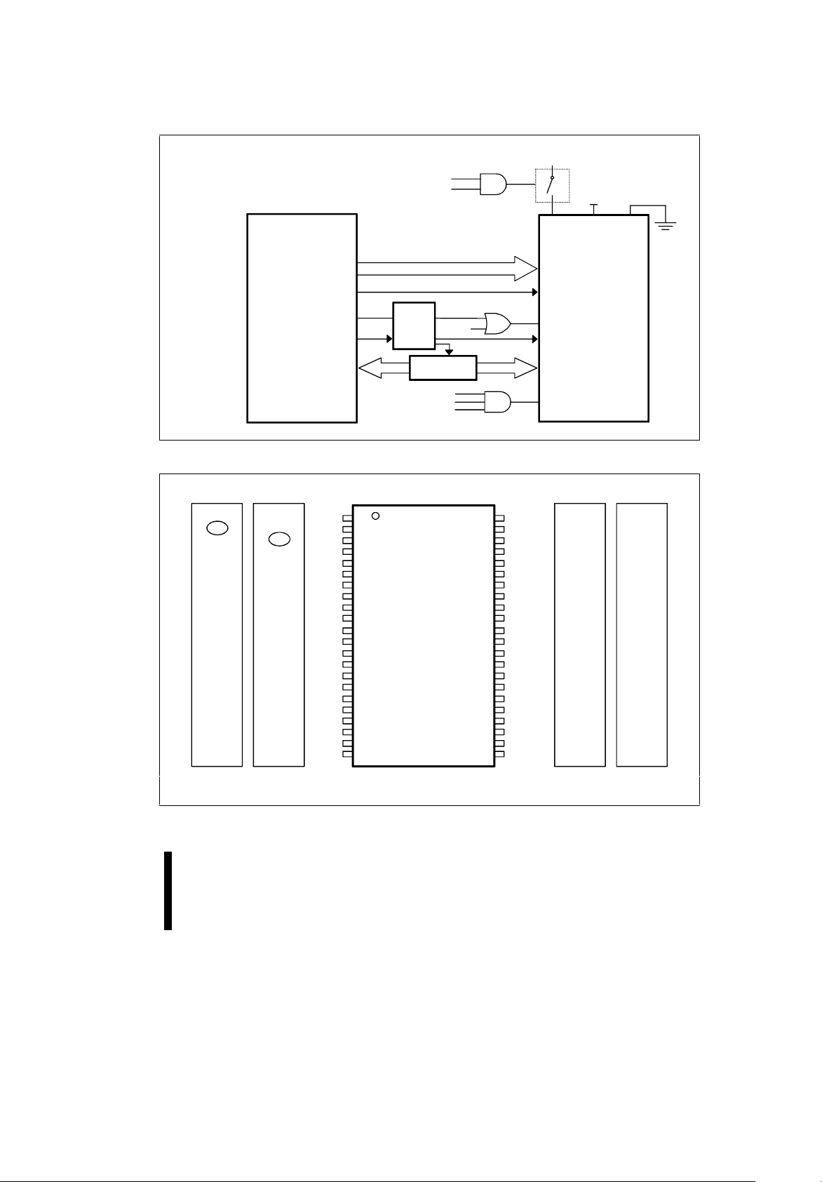
Intel386™ EX
Microprocessor
GPIO
GPIO
RESET#
PWRGOOD
PLD
Intel
28F200-T
RP#
V
GPIO
RESET#
WP#
BYTE#
5V
5V
PP
PLD
Transceiver
0542-01
Figure 1. 28F200BX Interface to Intel386™ Microprocessor
AB28F200
44-Lead PSOP
0.525" x 1.110"
TOP VIEW
GND
WE#
RP#
BYTE#
A
8
A
9
A
11
A
12
A
13
A
14
A
16
DQ
7
DQ
14
DQ
6
DQ
13
DQ
12
DQ
4
V
CC
DQ
5
A
10
A
15
32
31
30
29
28
27
26
25
24
23
33
34
35
36
37
38
39
40
41
42
43
44
CE#
WP#
GND
OE#
A
7
A
5
A
6
A
4
A
3
A
2
A
1
A
0
DQ
0
DQ
8
DQ
1
DQ
9
DQ
2
DQ
10
DQ
3
DQ
11
22
21
20
19
17
18
1
2
3
4
5
6
7
8
9
10
11
12
13
14
16
15
V
PP
NC
CE#
WP#
GND
OE#
A
7
A
5
A
6
A
4
A
3
A
2
A
1
A
0
DQ
0
DQ
8
DQ
1
DQ
9
DQ
2
DQ
10
DQ
3
DQ
11
V
PP
GND
WE#
RP#
BYTE#
A
8
A
9
A
11
A
12
A
13
A
14
A
16
DQ
7
DQ
14
DQ
6
DQ
13
DQ
12
DQ
4
V
CC
DQ
5
A
10
A
15
28F400 28F400
DQ
15 -1
/A DQ
15 -1
/A
CE#
GND
OE#
A
7
A
5
A
6
A
4
A
3
A
2
A
1
A
0
DQ
0
DQ
8
DQ
1
DQ
9
DQ
2
DQ
10
DQ
3
DQ
11
V
PP
28F800
GND
WE#
RP#
BYTE#
A
8
A
9
A
11
A
12
A
13
A
14
A
16
DQ
7
DQ
14
DQ
6
DQ
13
DQ
12
DQ
4
V
CC
DQ
5
A
10
A
15
28F800
DQ
15 -1
/A
A
17
A
17
A
18
0542_02
NOTE:
Pin 2 is DU for BX 12V V
PP
Versions.
Figure 2. 44-Lead PSOP Lead Configuration for x8/x16 28F200 Is Compatible with 4 and 8 Mbit.

A28F200BR E
8
ADVANCE INFORMATION
1.5 Pin Descriptions
Table 1. 28F200 Pin Descriptions
Symbol Type Name and Function
A0 - A
16
INPUT ADDRESS INPUTS for memory addresses. Addresses are internally
latched during a write cycle.
A
9
INPUT ADDRESS INPUT: When A9 is at VHH the signature mode is accessed.
During this mode, A
0
decodes between the manufacturer and device IDs.
When BYTE# is at a logic low, only the lower byte of the signatures are
read. DQ
15/A-1
is a don’t care in the signature mode when BYTE# is low.
DQ0-DQ7INPUT/OUTPUT DATA INPUTS/OUTPUTS: Inputs array data on the second CE# and
WE# cycle during a Program command. Inputs commands to the
Command User Interface when CE# and WE# are active. Data is
internally latched during the Write cycle. Outputs array, Intelligent
Identifier and Status Register data. The data pins float to tri-state when
the chip is de-selected or the outputs are disabled.
DQ8-DQ15INPUT/OUTPUT DATA INPUTS/OUTPUTS: Inputs array data on the second CE# and
WE# cycle during a Program command. Data is internally latched during
the Write cycle. Outputs array data. The data pins float to tri-state when
the chip is de-selected or the outputs are disabled as in the byte-wide
mode (BYTE# = “0”). In the byte-wide mode DQ
15/A-1
becomes the lowest
order address for data output on DQ
0
-DQ7.
CE# INPUT CHIP ENABLE: Activates the device’s control logic, input buffers,
decoders and sense amplifiers. CE# is active low. CE# high de-selects
the memory device and reduces power consumption to standby levels. If
CE# and RP# are high, but not at a CMOS high level, the standby current
will increase due to current flow through the CE# and RP# input stages.
OE# INPUT OUTPUT ENABLE: Enables the device’s outputs through the data buffers
during a read cycle. OE# is active low.
WE# INPUT WRITE ENABLE: Controls writes to the Command Register and array
blocks. WE# is active low. Addresses and data are latched on the rising
edge of the WE# pulse.
RP# INPUT RESET/DEEP POWER-DOWN: Uses three voltage levels (VIL, VIH, and
V
HH
) to control two different functions: reset/deep power-down mode and
boot block unlocking. It is backwards-compatible with the 28F200BX/BL.
When RP# is at logic low, the device is in reset/deep power-down
mode, which puts the outputs at High-Z, resets the Write State Machine,
and draws minimum current.
When RP# is at logic high, the device is in standard operation. When
RP# transitions from logic-low to logic-high, the device defaults to the
read array mode.
When RP# is at V
HH
, the boot block is unlocked and can be
programmed or erased. This overides any control from the WP# input.

E A28F200BR
9
ADVANCE INFORMATION
Table 1. 28F200 Pin Descriptions
(Continued)
Symbol Type Name and Function
WP# INPUT WRITE PROTECT: Provides a method for unlocking the boot block in a
system without a 12V supply.
When WP# is at logic low, the boot block is locked, preventing
program and erase operations to the boot block. If a program or erase
operation is attempted on the boot block when WP# is low, the
corresponding status bit (bit 4 for program, bit 5 for erase) will be set in
the Status Register to indicate the operation failed.
When WP# is at logic high, the boot block is unlocked and can be
programmed or erased.
NOTE: This feature is overridden and the boot block unlocked when RP#
is at V
HH
. See Section 3.4 for details on write protection.
BYTE# INPUT BYTE# ENABLE: Controls whether the device operates in the byte-wide
(x8) mode or the word (x16) mode. The BYTE# input must be controlled
at CMOS levels to meet the CMOS current specification in the standby
mode.
When BYTE# is at logic low, the byte-wide mode is enabled. A 19-bit
address is applied on A
-1
to A17, and 8 bits of data is read and written on
DQ
0
-DQ7.
When BYTE# is at logic high, the word-wide mode is enable. An 18-bit
address is applied on A
0
to A17 and 16 bits of data is read and written on
DQ
0
- DQ15.
V
CC
DEVICE POWER SUPPLY: 5.0V ± 10%
V
PP
PROGRAM/ERASE POWER SUPPLY: For erasing memory array blocks
or programming data in each block, a voltage either of 5V ± 10% or 12V ±
5% must be applied to this pin. When V
PP
< V
PPL
K
all blocks are locked
and protected against Program and Erase commands.
GND GROUND: For all internal circuitry.
NC NO CONNECT: Pin may be driven or left floating.
2.0 PRODUCT DESCRIPTON
2.1 Memory Blocking Organization
This product family features an asymmetricallyblocked architecture enhancing system memory
integration. Each block can be erased
independently of the others up to 10, 000 t imes . The
block sizes have been chosen to optimize their
functionality for common appli cations of nonvolatile
storage. For the address locations of the blocks,
see the memory maps in Figure 3.
2.1.1 ONE 16-KB BOOT BLOCK
The boot block is intended to repl ace a dedicated
boot PROM in a microprocess or or microcontrollerbased system. The 16-Kbyte (16,384 bytes) boot
block is located at either the top (denoted by -T
suffix) or the bottom (-B suffix) of the address m ap
to accommodate different microproces sor protocols
for boot code location. This boot block features
hardware controllable write-protection to protec t the
crucial microprocessor boot code from accidental
erasure. The protection of the boot block is
controlled using a combinati on of the V
PP
, RP#, and
WP# pins, as is detailed in Table 8.

A28F200BR E
10
ADVANCE INFORMATION
2.1.2 TWO 8-KB PARAMETER BLOCKS
The boot block architecture includes parameter
blocks to facilitate storage of frequently updated
small parameters that would normally require an
EEPROM. By using software techniques, the by terewrite functionality of EEPROMs can be emulated.
These techniques are detailed in Intel’s AP-604,
“Using Intel’s Boot B lock Flash Memory Parameter
Blocks to Replace EEPROM.” Each boot block
component contains two paramet er blocks of eight
Kbytes (8,192 bytes) each. The parameter blocks
are not write-protectable.
2.1.3 ONE 96-KB + THREE 128-KB MAIN
BLOCKS
After the allocation of address space to the boot
and parameter blocks, the remainder is divided into
main blocks for data or code storage. Each 2-Mbit
device contains one 96-Kbyte (98,304 byte) block
and one 128-Kbyte (131,072 byte) block. See the
memory maps for each device for more information.
3.0 PRODUCT FAMILY PRINCIPLES
OF OPERATION
Flash memory augments EPROM funct ionality with
in-circuit electrical program and erase. The boot
block flash family utilizes a Command User
Interface (CUI and automated algori thms to simpli fy
program and erase operations. The CUI allows for
100% TTL-level control inputs, f ixed power s upplies
during erasure and programming, and maximum
EPROM compatibility.
When V
PP
< V
PPLK
, the device will only successfully
execute the following commands: Read Array,
Read Status Register, Clear Status Register and
intelligent identifier mode. The device provides
standard EPROM read, standby and output disable
operations. Manufacturer identification and device
Identification data c an be accessed through the CUI
or through the standard EPROM A
9
high voltage
access (V
ID
) for PROM programming equipment.
The same EPROM read, standby and output
disable functions are avai lable when 5V or 12V is
applied to the V
PP
pin. In addition, 5V or 12V on
V
PP
allows program and erase of the device. All
functions associ ated wit h alt ering mem ory c ontent s:
Program and Erase, Intelligent Identifier Read, and
Read Status are accessed via the CUI.
The purpose of the Write State Machine (WS M) is
to completely automate the programming and
erasure of the device. The WSM will begin
operation upon receipt of a signal from the CUI and
will report status back through a Status Register.
The CUI will handle the WE# interface to the data
and address latches, as well as system software
requests for status while the WSM is in operation.
28F200-B
128-Kbyte MAIN BLOCK
8-Kbyte PARAMETER BLOCK
16-Kbyte BOOT BLOCK
8-Kbyte PARAMETER BLOCK
96-Kbyte MAIN BLOCK
00000H
0FFFFH
10000H
1BFFFH
1C000H
1CFFFH
1D000H
1DFFFH
1E000H
1FFFFH
28F200-T
128-Kbyte MAIN BLOCK
8-Kbyte PARAMETER BLOCK
16-Kbyte BOOT BLOCK
8-Kbyte PARAMETER BLOCK
96-Kbyte MAIN BLOCK
1FFFFH
10000H
0FFFFH
04000H
03FFFH
03000H
02FFFH
02000H
01FFFH
00000H
0542-03
Figure 3. 28F200-T/B Memory Maps

E A28F200BR
11
ADVANCE INFORMATION
Table 2. Bus Operations for Word-Wide Mode (BYTE# = VIH)
Mode Notes RP# CE# OE# WE# A
9
A0V
PP
DQ
0-15
Read 1,2,3 V
IH
V
IL
V
IL
V
IH
XXX D
OUT
Output Disable V
IH
V
IL
V
IH
V
IH
X X X High Z
Standby V
IH
V
IH
X X X X X High Z
Deep Power-Down 9 V
IL
X X X X X X High Z
Intelligent Identifier (Mfr) 4 V
IH
V
IL
V
IL
V
IH
V
ID
V
IL
X 0089 H
Intelligent Identifier
(Device)
4,5 V
IH
V
IL
V
IL
V
IH
V
ID
V
IH
X See Table 4
Write 6,7,8 V
IH
V
IL
V
IH
V
IL
XXX D
IN
Table 3. Bus Operations for Byte-Wide Mode (BYTE# = VIL)
Mode Notes RP# CE# OE# WE# A
9
A
0
A-1V
PP
DQ
0-7
DQ
8-14
Read 1,2,3 V
IH
V
IL
V
IL
V
IH
XXXXD
OUT
High Z
Output Disable V
IH
V
IL
V
IH
V
IH
X X X X High Z High Z
Standby V
IH
V
IH
X X X X X X High Z High Z
Deep PowerDown
9VILX X X X X X X High Z High Z
Intelligent
Identifier (Mfr)
4VIHV
IL
V
IL
V
IH
V
ID
V
IL
X X 89H High Z
Intelligent
Identifier
(Device)
4,5 V
IH
V
IL
V
IL
V
IH
V
ID
V
IH
X X See
Table 4
High Z
Write 6,7,8 V
IH
V
IL
V
IH
V
IL
XXXXDINHigh Z
NOTES:
1. Refer to DC Characteristics.
2. X can be V
IL
, VIH for control pins and addresses, V
PPLK
or V
PPH
for VPP.
3. See DC Characteristics for V
PPLK
, V
PPH
1, V
PPH
2, VHH, V
ID
voltages.
4. Manufacturer and Device codes may also be accessed via a CUI write sequence, A
1-A17
= X, A1-A18 = X.
5. See Table 4 of Device IDs.
6. Refer to Table 5 for valid D
IN
during a write operation.
7. Command writes for Block Erase or Word/ByteProgram are only executed when V
PP
= V
PPH
1 or V
PPH
2.
8. To program or erase the boot block, hold RP# at V
HH
or WP# at VIH.
9. RP# must be at GND ± 0.2V to meet the maximum deep power-down current specified.
 Loading...