

Intel Xeon 5080 (HH80555KH1094M) Integration Guide for New Dual-Core Intel Xeon Processor-Based Servers With the Microsoft Windows Server 2003 (Rev 1.1)

Integration Guide for New
Dual-Core Intel
®
Xeon®
Processor-Based Servers (or
Workstations)
With the Microsoft* Windows* Server 2003 64-Bit
Edition Operating System
Rev 1.
1

Integration Guide for New Dual-Core Intel® Xeon® Processor-Based Servers (or Workstations) Rev 1.1
Revision History
Date Revision Notes Product Code
2008.06 Rev 1.1 Revised Version
Disclaimers
The information contained in this document is provided for informational purposes only and represents the current
view of Intel Corporation (“Intel”) and its contributors (“Contributors”) as of the date of publication. Intel and the
Contributors make no commitment to update the information contained in this document, and Intel reserves the right
to make changes at any time, without notice.
DISCLAIMER.
REPRESENTATIONS OF ANY KIND WITH RESPECT TO PRODUCTS REFERENCED HEREIN, WHETHER SUCH PRODUCTS
ARE THOSE OF INTEL, THE CONTRIBUTORS, OR THIRD PARTIES. INTEL, AND ITS CONTRIBUTORS EXPRESSLY
DISCLAIM ANY AND ALL WARRANTIES, IMPLIED OR EXPRESS, INCLUDING WITHOUT LIMITATION, ANY WARRANTIES
OF MERCHANTABILITY, FITNESS FOR ANY PARTICULAR PURPOSE, NON-INFRINGEMENT, AND ANY WARRANTY
ARISING OUT OF THE INFORMATION CONTAINED HEREIN, INCLUDING WITHOUT LIMITATION, ANY PRODUCTS,
SPECIFICATIONS, OR OTHER MATERIALS REFERENCED HEREIN. INTEL, AND ITS CONTRIBUTORS DO NOT
WARRANT THAT THIS DOCUMENT IS FREE FROM ERRORS, OR THAT ANY PRODUCTS OR OTHER TECHNOLOGY
DEVELOPED IN CONFORMANCE WITH THIS DOCUMENT WILL PERFORM IN THE INTENDED MANNER, OR WILL BE FREE
FROM INFRINGEMENT OF THIRD PARTY PROPRIETARY RIGHTS, AND INTEL, AND ITS CONTRIBUTORS DISCLAIM ALL
LIABILITY THEREFOR.
INTEL, AND ITS CONTRIBUTORS DO NOT WARRANT THAT ANY PRODUCT REFERENCED HEREIN OR ANY PRODUCT OR
TECHNOLOGY DEVELOPED IN RELIANCE UPON THIS DOCUMENT, IN WHOLE OR IN PART, WILL BE SUFFICIENT,
ACCURATE, RELIABLE, COMPLETE, FREE FROM DEFECTS OR SAFE FOR ITS INTENDED PURPOSE, AND HEREBY
DISCLAIM ALL LIABILITIES THEREFOR. ANY PERSON MAKING, USING OR SELLING SUCH PRODUCT OR TECHNOLOGY
DOES SO AT HIS OR HER OWN RISK.
Licenses may be required
trademarks, copyrights or other intellectual proprietary rights covering subject matter contained or described in this
document. No license, express, implied, by estoppels or otherwise, to any intellectual property rights of Intel or any
other party is granted herein. It is your responsibility to seek licenses for such intellectual property rights from Intel
and others where appropriate.
Limited License Grant
internal distribution only. You may not distribute this document externally, in whole or in part, to any other person
or entity.
LIMITED LIABILITY
OTHER THIRD PARTY, FOR ANY LOST PROFITS, LOST DATA, LOSS OF USE OR COSTS OF PROCUREMENT OF
SUBSTITUTE GOODS OR SERVICES, OR FOR ANY DIRECT, INDIRECT, SPECIAL OR CONSEQUENTIAL DAMAGES
ARISING OUT OF YOUR USE OF THIS DOCUMENT OR RELIANCE UPON THE INFORMATION CONTAINED HEREIN,
UNDER ANY CAUSE OF ACTION OR THEORY OF LIABILITY, AND IRRESPECTIVE OF WHETHER INTEL, OR ANY
CONTRIBUTOR HAS ADVANCE NOTICE OF THE POSSIBILITY OF SUCH DAMAGES. THESE LIMITATIONS SHALL APPLY
NOTWITHSTANDING THE FAILURE OF THE ESSENTIAL PURPOSE OF ANY LIMITED REMEDY.
Intel, Intel NetBurst, Intel Xeon, Intel i960, Intel Inside and the Intel logos are trademarks or registered
trademarks of Intel Corporation or its subsidiaries in the United States and other countries.
Copyright © Intel Corporation, 2002. All rights reserved.
*
Other brands and names are the property of their respective owners.
THIS DOCUMENT, IS PROVIDED “AS IS.” NEITHER INTEL, NOR THE CONTRIBUTORS MAKE ANY
. Intel, its contributors and others may have patents or pending patent applications,
. Intel hereby grants you a limited copyright license to copy this document for your use and
. IN NO EVENT SHALL INTEL, OR ITS CONTRIBUTORS HAVE ANY LIABILITY TO YOU OR TO ANY
2

Integration Guide for New Dual-Core Intel® Xeon® Processor-Based Servers (or Workstations) Rev 1.1
Table of Contents
1 Introduction.....................................................................................4
1.1 Document Overview ....................................................................... 4
1.2 Target Audience ............................................................................ 4
1.3 Document Objective....................................................................... 4
2 Platform Overview.............................................................................5
3 Plaform Hardware Requirements ..........................................................7
3.1 Motherboard Integration ................................................................. 7
3.2 Fully Buffered DIMM (FBDIMM) Memory ............................................ 8
3.3 Processor and Thermal Solutions...................................................... 8
3.4 Server System Infrastructure (SSI) Compliant Chassis...................... 13
3.5 SSI Compliant Power Supply ......................................................... 14
3.6 Other System Components............................................................ 16
4 Recommended Server Components ....................................................19
5 Setup and Configuration of Microsoft* Windows* 2003 64-Bit Edition .........20
6 Setup and Configuration of VMWare* Workstation 5.5 (Windows) ...............27
3

Integration Guide for New Dual-Core Intel® Xeon® Processor-Based Servers (or Workstations) Rev 1.1
1 Introduction
1.1 Document Overview
This document outlines the procedures for deploying a new Dual-Core Intel® Xeon® processor-based
server (or workstation) with the Microsoft* Windows* Server 2003 64-Bit Edition Operating System.
The process of properly integrating a new server (or workstation) system typically requires access to
several source documents, each containing pertinent information. The purpose of this document is to
extract the essential information needed from the various sources and place it into one comprehensive
document.
See the References section of this document for the complete list of source documents used.
In addition this document will provide any useful “tips and tricks” that may have been discovered during
the development of this system.
1.2 Target Audience
z Intel Channel program members who currently integrate Intel® Server Products or are new to server
platforms
z System integrators who deploy the new Dual-Core Intel® Xeon® processor-based servers (or
workstations)
1.3 Document Objective
Our intent is to better enable system integrators in meeting the competitive challenges they face in the
server market and to keep program members up-to-date on emerging server technologies. By following
the steps outlined in this document you will be able to deploy a stable new Dual-Core Intel
processor-based server (or workstation) using Intel components running Microsoft* Windows* Server
2003 64-Bit Edition Operating System in a timely and effective manner.
®
Xeon®
4

Integration Guide for New Dual-Core Intel® Xeon® Processor-Based Servers (or Workstations) Rev 1.1
2 Platform Overview
The new platform consists of the Dual-Core Intel® Xeon® processor 5000 sequence, Intel® 5000P or
®
Intel
5000V or Intel® 5000X Memory Control Hub, and the Intel® 6311ESB or 6312ESB I/O Controller
Hub. The new Dual-Core Intel® Xeon® processor-based server enhances platform performance,
bandwidth, flexibility, and I/O integration. Intel’s innovation around the new platform is a leap ahead of
our prior generation servers and offers the best business server platform for IT available in the
marketplace.
z Lower Power 64-bit Dual-Core Processors
z Intel
z Hardware assisted Intel® Virtualization Technology (VT)
z New dual independent point-to-point bus
z Fully Buffered DDR2 DIMM Memory (FBDIMM)
z Intel
z Embedded RAID technology (optional)
z Quad-Core support
z Intel® EM64T 64 bit computing (standard since 2004)
z PCI Express
z Intel
®
Core™ Micro-Architecture
®
I/O Acceleration Technology (optional)
*
(standard since 2004)
®
Execute Disable Bit (XD-bit) (since 2005)
z Intel® Software Optimization Tools (optional)
®
z Intel
New Dual Independent Point-to-Point Bus
¾ To balance the higher throughput requirements from dual core CPUs, Intel comes up with the new
Power Efficient Micro Architecture
¾ Power-efficient Intel
¾ Improve Total Cost of Ownership (TCO) and server density with 80W Dual-Core Intel
Intel
¾ Intel® Virtualization Technology is part of a collection of premier Intel designed and manufactured
Power Efficiency Tools (optional)
front side bus architecture – DIB (Dual Independent bus). This new point to point bus enables faster
FSB speeds (1066 MHZ and 1333 MHZ), much higher throughput (17-21GB/s transfer rate) and
better performance.
®
Xeon® processor-based servers feature Intel® CoreTM Micro-Architecture,
software and management tools to help you maximize performance density while providing
tremendous improvements in performance, utilization and reliability
®
Xeon®
processor 5100 series based servers that deliver up to 2x the performance of yesterday’s servers
with up to 3x the power efficiency
®
Virtualization Technology
silicon technologies that deliver new and improved computing benefits for home, business users,
and IT managers. Virtualization enhanced by Intel
run multiple operating systems and applications in independent partitions. With virtualization, one
®
Virtualization Technology will allow a platform to
5

Integration Guide for New Dual-Core Intel® Xeon® Processor-Based Servers (or Workstations) Rev 1.1
computer system can function as multiple ‘virtual’ systems. With processor and I/O enhancements
to Intel’s various platforms, Intel® Virtualization Technology can improve the performance and
robustness of today’s software-only virtual machine solutions.
®
Intel
Active Server Manager
¾ Intel® Active Server Manager (ASM) delivers the best combination of integrated management
hardware, software, and firmware required to manage today's server environments. Intel
®
ASM can
help IT Track the health and status of connected servers, remotely diagnose and repair systems
even when the operating system is not running, and keep software and virus protection up-to-date.
Intel ASM features, launching with the Dual-Core Intel
®
Xeon® processor 5000 sequence, includes:
9 Support for IPMI 2.0
9 Remote power control and asset management
9 Advanced features such as IDE-redirection and remote monitoring (KVM pass-through)
capability.
®
Intel
6311ESB/6312ESB I/O Controller Hub
¾ Intel® 6311ESB/6312ESB I/O Controller Hub is a highly integrated I/O chipset. It integrates bridge
functionality for PCI Express*, PCI-X*, conventional PCI*, LPC, USB*, SATA*, IDE and SMBus, and
Dual-Gigabit Ethernet MAC components as well as numerous board management functions. It
provides for all system I/O, allowing for simpler system board architectures and smaller board areas
than if discrete components were used.
Intel® I/O Acceleration Technology
®
¾ Intel
I/O Acceleration Technology, unlike NIC-centric solutions (such as TCP Offload Engine), is a
platform level solution that addresses all packet and payload processing bottlenecks throughout the
server platform. It increases CPU efficiency and delivers data to and from applications faster than
possible with current server platforms. Most importantly, Intel
®
I/OAT scales with future platform
improvements, providing a path for further reducing infrastructure costs by consolidating hardware
and software, and ultimately growing your business.
Fully Buffered DIMM (FBDIMM) Memory Technology
¾ Fully Buffered DIMM (FBDIMM) memory enables both increased capacity and memory bandwidth
requirements needed to keep pace with the processor and I/O performance enhancements on
today's dual-core server processors.
¾ FBDIMM technology offers better RAS (reliability, availability, serviceability) by extending the
currently available ECC (error-correcting code, a method of checking the integrity of data in DRAM)
to include protection of commands and address data. Additionally, FBDIMM technology
automatically retries when an error is detected, allowing for uninterrupted operation in case of
transient errors.
¾ The FBDIMM channel pin count is approximately 69 pins per channel, compared with about 240 pins
for today's parallel channel. This results in less routing complexity and less routing area between the
memory controller and DIMMs, thereby saving board cost to system manufacturers.
6

Integration Guide for New Dual-Core Intel® Xeon® Processor-Based Servers (or Workstations) Rev 1.1
3 Plaform Hardware Requirements
This hardware integration section demonstrates the base line of how to integrate a server system using
a motherboard based on new Dual-Core Intel
and power supply, as well as FBDIMM memory and other standard off-the-shelf components. The target
audiences of this integration guideline are system designers and system integrators. The validation of
server functions and performance optimization will not be discussed here.
As a functional server, new Dual-Core Intel
building blocks:
z Motherboard
z Memory
z Processor and Intel designed thermal solution
z Chassis
z Power supply
z Other system components
®
Xeon® processors together with an SSI compliant chassis
®
Xeon® processor-based servers should include the following
3.1 Motherboard Integration
The server boards should be compliant with one of the following Server System Infrastructure (SSI)
specifications for building block compatibility and interchangeability between different blocks:
z EEB 3.61
¾ EEB (Entry- level Electronics Bay) 3.51 for Entry Pedestal Servers and Workstations.
z TEB 2.11
¾ TEB (Thin Electronics Bay) 2.11 for rack mount optimized servers.
z CEB 1.1
¾ CEB (Compact Electronics Bay) 1.1 for value form factor servers.
The following system features are defined by the SSI specification:
z Baseboard maximum volumetric and mounting-hole locations
z Power and signal connector pin-outs
z ATX-compliant I/O aperture and dimensions that define its location
z Chassis keep-out volume and board/processor mounting requirements
USEFUL INTEGRATION TIPS:
z SSI specifications can be obtained from SSI website at http://ww.ssiforum.org
z The motherboard should be SSI-compliant, which defines motherboard dimension, component and
chassis attachment interface, board block layout directions, as well as power connectors
7

Integration Guide for New Dual-Core Intel® Xeon® Processor-Based Servers (or Workstations) Rev 1.
3.2 Fully Buffered DIMM (FBDIMM) Memory
Fully Buffered DIMM (FBDIMM) memory provides increased bandwidth and capacity for new Dual-Core
Intel® Xeon® processor-based servers. It increases system bandwidth up to 21GB/s (with DDR2-667
FBD memory), and increased memory capacity up to 64GB in a 4 channel 16 DIMM server system.
FBDIMM memory has different versions in terms of the DRAM used in the memory module: DDR2-533
FBD memory and DDR2-667 FBD memory, and has different capacities: 512MB, 1GB, 2GB and 4GB.
DIMM pairs must be identical with respect to size, speed and manufacturer.
The picture below illustrates an example of an FBDIMM.
Figure 3.2.2 FBDIMM Example
USEFUL INTEGRATION TIPS
1) To take advantage of the Intel® E5000P chipset, Intel recommends using at least 4 FBDIMMs in new
Dual-Core Intel® Xeon® processor-based servers to achieve optimal throughput. Example: For 2GB
configurations use 4 x 512M FBDIMMs rather than 2 x 1GB FBDIMMs.
2) To boot up the system, one FBDIMM should be installed in the first FBDIMM slot.
3) Intel has completed FBDIMM validation for different memory configurations. System integrators can
find the complete list of tested memory modules at:
http://developer.intel.com/technology/memory/
3.3 Processor and Thermal Solutions
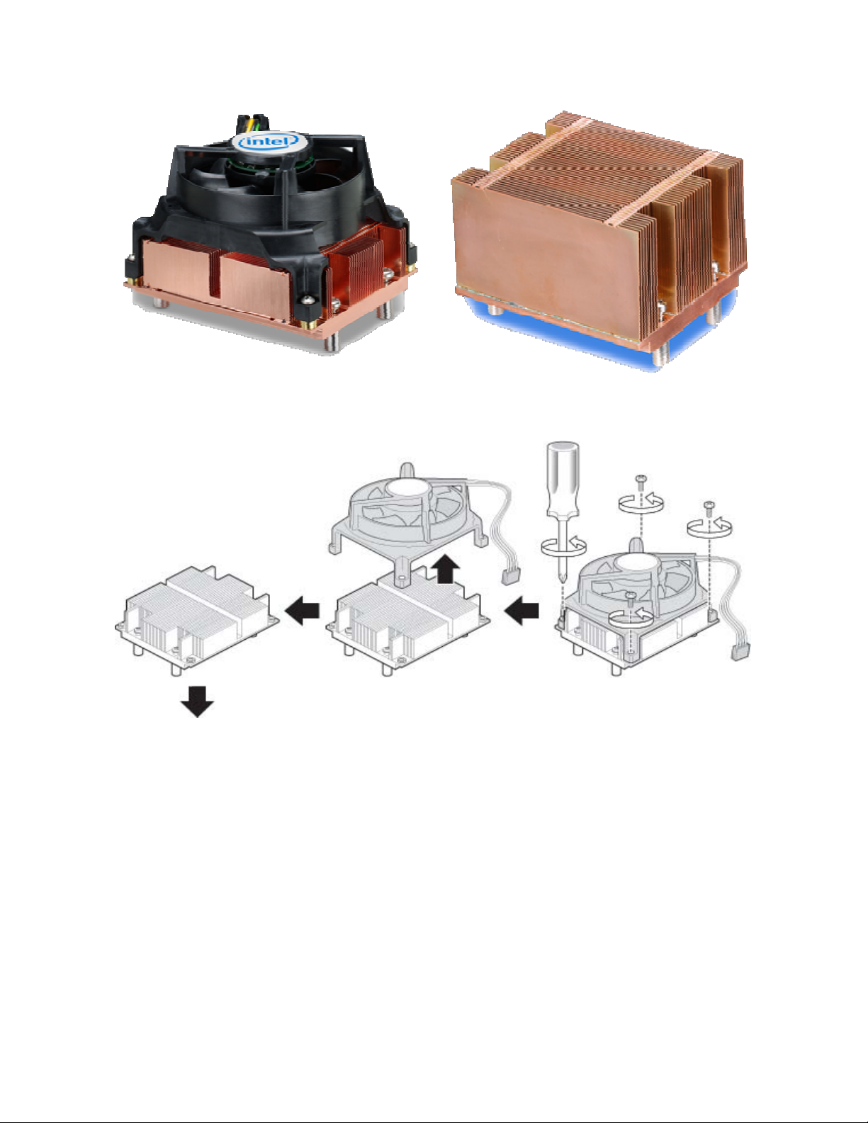
The boxed version of the Dual-Core Intel® Xeon® processor 5000 sequence supports a passive 2U+
thermal solution, as well as a combination active/1U passive solution (as figure 3.3.1 and 3.3.2 shows).
The 2U passive solution can be used in 2U+ rack chassis and pedestal systems; the active solution is a
combined solution that supports pedestal chassis with the fan attached, and 1U rack systems with the fan
removed (as figure 3.3.3 shows).
8
Integration Guide for New Dual-Core Intel® Xeon® Processor-Based Servers (or Workstations) Rev 1.1
Figure 3.3.1 Active solution Figure 3.3.2 2U passive solution
Figure 3.3.3 Combined Active Solution
The boxed Dual-Core Intel® Xeon® processor 5000 sequence requires the heat sink to be directly
attached to the chassis, in order to securely attach the heat sink. As shown in Figure 3.3.4, verify the
Common Enabling Kit (CEK) spring is installed on both processor sockets before motherboard installation.
Refer to your motherboard documentation for more information, or contact your motherboard
manufacturer to obtain a CEK spring for each processor socket if not included with the motherboard.
9

Integration Guide for New Dual-Core Intel® Xeon® Processor-Based Servers (or Workstations) Rev 1.1
CEK Spring
Figure 3.3.4 Verify the CEK Spring is Installed for Each Processor Socket
Dual-Core Intel® Xeon® Processor Installation
CAUTION
When unpacking a processor, hold by the edge only to avoid touching the contacts.
A. Open the socket lever
1) Push the lever handle down and away from the socket to
release it.
2) Pull the lever and raise until it stops.
B. Open the load plate
1) Push the rear tab with your finger tip to bring the front end of the load plate up slightly.
2) Open the load plate as shown.
10

Integration Guide for New Dual-Core Intel® Xeon® Processor-Based Servers (or Workstations) Rev 1.1
C. Remove the processor protective cover
1) Take the processor out of the box remove the protective shipping
cover.
D. Remove socket protective cover
1) Grasp the socket protective cover tab and pull away from the load plate as shown.
2) Remove the socket protective cover and store for future use.
E. Install the processor
1) Orient the processor with the socket so that the processor cut-outs match the socket notches.
2) Install the processor as shown.
F. Close load plate and socket lever
1) Close the load plate all the way as shown.
2) With your finger, push down on the load plate as shown.
3) Close the socket lever and ensure that the load plate tab
engages under the socket lever when fully closed.
11

Integration Guide for New Dual-Core Intel® Xeon® Processor-Based Servers (or Workstations) Rev 1.1
G. Removing the plastic shield for the heat sink
H. Attach the heat sink to the chassis
I. Tighten screws
J. Connect the fan header if you are using the active solution.
12

Integration Guide for New Dual-Core Intel® Xeon® Processor-Based Servers (or Workstations) Rev 1.1
3.4 Server System Infrastructure (SSI) Compliant
Chassis
Server System Infrastructure (SSI) compliant chassis provides component attachment, adequate airflow,
electronic emission protection, as well as data storage and management. The quality of chassis will
greatly impact server system performance. Compared to a desktop PC chassis, the requirement for
server chassis on thermal, power supplies and data management is much higher.
USEFUL INFORMATION
z Rack mount chassis include 1U rack chassis and 2U+ chassis. The height of 1U chassis is 1.75’’ and
2U chassis is 3.5’’.
z SSI specifications can be obtained from SSI website at http://ww.ssiforum.org
3.4.1 Chassis Form Factor
Pedestal and rack mount are two types of form factors. Pedestal chassis should be compliant to EEB 3.61
or CEB 1.1, and rack mount chassis should be compliant to TEB 2.11.
EEB is mainly used for entry-level servers with larger form factors, and CEB is targeted at value servers
with smaller form factors and lower cost.
The EEB chassis can install one motherboard based on the ATX form factor ‘stretched’ to 12” X 13”, a size
sometimes known as “full ATX”. This represents the maximum size of board in one EEB chassis, though
smaller sizes are possible. The maximum motherboard size in CEB Chassis is 12’’ X 10.5’’; there is a 2.5’’
difference in length. The TEB baseboard is based on the EEB baseboard size of 12” X 13”.
There are specific requirements on rack chassis width and height to make sure they are compliant to rack
system. The 1U and 2U maximum height dimensions allow for 1.3mm clearance between adjacent
systems when they are installed in a typical rack configuration. The 445.0mm maximum width includes
chassis width, rails, and tolerance; chassis with typical 3/8” roller-bearing slide rails are limited to
428.0mm. System typical depth is 610mm to 660mm.
13

Integration Guide for New Dual-Core Intel® Xeon® Processor-Based Servers (or Workstations) Rev 1.1
Figure 3.4.1
3.5 SSI Compliant Power Supply
The power supply provides adequate power to the processor, motherboard and other key components. As
shown by research data, most of the server shut-down issues are caused by a power supply failure,
including over-heat protection and over-current protection. So, choosing a reliable power supply is an
important consideration for proper server integration.
Based on the SSI form factor, there are three types of SSI power supplies, EPS1U is used in 1U rack
mount server, EPS2U is used in 2U rack mount server and EPS12V is used in pedestal server. Additional
to that, there are redundant power supplies for 2U and pedestal server, they are ERP2U and ERP12V
respectively.
3.5.1 Mechanical form factors
Below are detailed mechanical dimensions for SSI compliant power supplies:
Form Factor Application Height Width Length
EPS1U 1U rack 40mm 106mm 355mm
EPS2U 2U rack 42.2mm 106mm 348.2mm
ERP2U 2U rack Redundant
EPS12V Pedestal 86mm 150mm 140mm (<450W)
ERP12V Pedestal Redundant 86mm 150mm 260mm
Table 3.4.3 Power Supply Form Factors
There is no specified requirement on position and length of wire harness of power supply, the base line
is wire harness must make integration and wire plug easier and more beneficial for maintaining.
Some time, the power supply will influence cable layout because of card edge dimensions and small gaps
between the power supply and the chassis, especially in rack mount server where cable layout is
important may impact system thermal performance.
83mm 108mm
400mm(Regular)
350mm(Hot Swap)
180mm (450W~750W)
230mm (>800W)
3.5.2 Power level and output rails
Below figure is one typical power budget in one new Dual-Core Intel® Xeon® based server system. There
are 8 rails recommended in SSI specification for the new platform compliant power supplies, as below:
Figure 3.4.11 System Power Level in 5000 Series Platform
14

Integration Guide for New Dual-Core Intel® Xeon® Processor-Based Servers (or Workstations) Rev 1.1
The following table provides recommendations for the power and current ratings for different form
factors:
Spec
EPS1U 600 10 21 16 16 16 16 0.5 3
EPS2U 700 24 30 16 16 16 16 0.5 3
ERP2U 750 24 30 16 16 16 16 0.5 3
EPS12V 650 24 30 16 16 16 16 0.5 3
ERP12V 700 24 30 16 16 16 16 0.5 3
Power
(W)
Table 3.4.4 SSI recommended power levels and current rating
+3.3V +5V 12V1 12V2 12V3 12V4 -12V +5VSB
Current Rating (A)
3.5.3 Power supply connectors
Normally, the power supply distribution board shall have the following output connectors and wire
harness configuration:
Connectors Pins No.
Base board power connector 24
Processor power connector 8
+12V4 base board power connector, required
for 700W, 750W and 800W power levels
4
Fan power with fan speed control 4
Peripheral power connectors 4
Floppy power connectors 4
Serial ATA power connectors 5
Server signal connectors 5
Table 3.4.5 SSI recommended power supply connectors
Integrators must ensure these power connectors provide the proper output and that they are connected
properly. Different colors have been used to mark different power output voltages. One power connector
may have several colors in one stripe along the colored wire
3.3VDC 3.3VRS +5VDC +12V1 +12V2 +12V3 +12V4 -12V 5VSB PS_ON
Orange
Orange
White
Red
Table 3.4.6 SSI recommended power supply triples color
Yellow Yellow Yellow
Black
Yellow
Blue Green
Blue Purple Green
3.5.4 Hot swap and redundant power supplies
15

Integration Guide for New Dual-Core Intel® Xeon® Processor-Based Servers (or Workstations) Rev 1.1
It is recommended to use the hot swap and redundant power supplies for new Dual-Core Intel® Xeon®
processor-based servers. Hot swapping a power supply is the process of inserting and extracting a
power supply from a server while it is operating, without interruption.
3.6 Other System Components
3.6.1 Hard drive
1) SCSI HDD
The SCSI specification was developed to provide a common interface that could be used across all
peripheral platforms and system applications. The SCSI interface addresses a wider range of
applications, such as Redundant Array of Independent Disks (RAID) storage, and has a broader
command set than the parallel ATA interface. The SCSI system contains the SCSI controller (initiator),
the SCSI bus (cable or backplane), and one or more target devices. The SCSI controller may be built into
the motherboard or housed on a SCSI host bus adapter (HBA) card in a PCI or PCI-X slot. Both
configurations are shown in Figure 3.6.1.
SCSI cables can connect up to 16 devices, including the SCSI controller. SCSI cables consist of 34 twisted
pairs of multi-stranded flexible copper wires for a total of 68 conductors. SCSI devices inside the server
are connected to the SCSI controller by a 68-pin ribbon cable. The ribbon cable has a connector at each
end and one or more connectors along its length. External SCSI devices are attached to the SCSI HBA by
a round 68-pin cable. Two sets of terminators, one at each end of the SCSI bus, prevent signal reflections
within the cables.
Figure 3.6.1 SCSI components
Since 1981, there have been seven generations of the SCSI protocol. Each new generation has doubled
the performance of the previous one (Figure 3.6.2). SCSI performance has ranged from an 8-bit,
single-ended interface transferring data up to 4 MB/s (SCSI-1) to the latest 16-bit, low-voltage
differential interface transferring data at 320 MB/s per channel (Ultra320 SCSI).
16

Integration Guide for New Dual-Core Intel® Xeon® Processor-Based Servers (or Workstations) Rev 1.1
Figure 3.6.2 Bandwidths of seven generations of SCSI
SCSI hard drives provide some benefits:
¾ Fast data transfer (up to 320 MB/s transfer rate per channel)
¾ High MTBF (Mean Time between Failures)
¾ Support multiple HDD on one channel, such as a single channel of Ultra 320 can support 15 hard
drivers, two channels can support up to 30 hard drivers, and all of hard drivers in the same
channel use only one IRG
¾ SCSI controller can offload some CPU tasks which used to handling the storage commands; CPU
utilization rate for SCSI HDD processing is low. This is good for multiple task system.
2) SATA HDD
Serial ATA 1.0 (SATA)
SATA specification was developed in 2001, SATA is the first generation of the new disk interface
technology replacing Parallel ATA. In desktops, SATA is expected to replace Parallel ATA as the
primary internal storage for PCs. SATA1.0 delivers a maximum data transfer rate of 1.5 Gb/sec (150
MB/sec) per port and its future roadmap shows growth to 6.0 Gb/sec (600 MB/sec). Advantages of
SATA include a point-to-point interconnect that enables full bandwidth available to each device,
lower pin-count, lower voltage, hot-plug capability, thin cabling, longer cable length and
register-level compatibility with Parallel ATA. These added features make SATA an option for DAS,
NAS and some Storage Area Network (SAN) systems where Parallel ATA may not have been
considered.
Serial ATA II (SATA II)
SATA II is the second-generation SATA disk interface technology currently under development by
the SATA working group. The SATA II specification picks up where SATA 1.0 left off, and will be
deployed in 2 phases. The first phase, called “Extensions to Serial ATA 1.0”, focuses primarily on
addressing the needs of servers and networked storage. These include queuing, enclosure services,
hot plug, cold presence detect, cabling and backplane improvements. The second phase is
anticipated to scale performance to 3.0 Gb/sec (300 MB/sec) per port. These combined
enhancements will make SATA II a good option for DAS, NAS and SAN storage systems where
price/performance and cost are key factors.
17

Integration Guide for New Dual-Core Intel® Xeon® Processor-Based Servers (or Workstations) Rev 1.1
3) SAS HDD
SAS (Serial Attached SCSI) is a point-to-point architecture in which all storage devices connect directly
to a SAS port rather than sharing a common bus as traditional SCSI devices do. Point-to-point links
increase data throughput and improve the ability to locate and fix disk failures. More importantly, the
SAS architecture solves the clock skew and signal degradation problems of parallel SCSI at higher
signaling rates. SAS inherits its command set from parallel SCSI, frame formats from Fibre Channel, and
physical characteristics from Serial ATA.
The SAS and SATA technologies have several common features, including low-voltage differential
signaling, 8b/10b encoding, and full duplex communication. The Serial Attached SCSI standards
committee designed the SAS infrastructure to be compatible with SATA drives, allowing the coexistence
of both storage technologies in the same system and opening the door to SATA scalability. Because the
SAS architecture features a proven SCSI command set, advanced command queuing, and advanced
verification/error correction, SAS is the ideal solution for mission-critical enterprise storage applications.
z Performance
The speed of the first-generation SAS link is 3.0 gigabits/second (Gb/s). The speed of the
second-generation SAS link will be 6.0 Gb/s . SAS links are full duplex; they send and receive
information simultaneously, thereby reducing a major source of latency. The SAS interface allows for
combining multiple links to create 2x, 3x, or 4x connections for scalable bandwidth.
z SAS/SATA interoperability
The SAS architecture enables system designs that deploy both SAS and SATA devices, a
breakthrough for enterprise customers. This capability provides a broad range of storage solutions
that give IT managers the flexibility to choose storage devices based on reliability, performance, and
cost.
z Greater scalability
Serial Attached SCSI enables highly scalable topologies—internal, external, or a combination of
both—to give manufacturers and customers the flexibility to design and deploy a range of solutions.
The Serial ATA Tunneling Protocol (STP) enables SAS HBAs to communicate with SATA devices
through expanders and, therefore, is key to SATA scalability in the SAS domain.
USEFUL INFORMATION
z More detail information about the disk interface technology can be found at
http://www.intel.com/technology/serialATA/pdf/NP2108.pdf
18

Integration Guide for New Dual-Core Intel® Xeon® Processor-Based Servers (or Workstations) Rev 1.1
4 Recommended Server Components
Before you begin system integration, you may want to become more familiar with some of the server
components. The following section contains a brief overview of the products used in this integration guide.
Intel recommends that before beginning system integration, the integrator sources all recommended
components needed to complete integration. A recommended list of components needed can be found
below.
Table 1- Recommended Server Components List
Server System
Boxed Intel Server Board
Qty: 1
Processor
Boxed Dual-Core Intel®
®
Xeon
processor
Qty: 2
Product code:
Intel® Server Board
S5000PSL
Product code:
Intel® Xeon®
Processor 5000
Series, or Xeon®
Processor 5100 Series
For more information please refer to:
http://intel.com/design/servers/boards/
For more information please refer to:
http://support.intel.com/support/processors/
xeon
Server Chassis
Intel Server Chassis
Qty: 1
Memory Configuration
512MB FBDIMM 533MHz
Qty: 4
Product code:
Intel® Server Chassis
SC5299-E
Product code:
Kingston*
KVR533D2S8F4/512
For more information please refer to:
http://intel.com/design/servers/chassis/
For more information please refer to:
http://developer.intel.com/technology/memo
ry/
19

Integration Guide for New Dual-Core Intel® Xeon® Processor-Based Servers (or Workstations) Rev 1.1
5 Microsoft* Windows* Server 2003 64-Bit
Edition Operating System Installation
Outline of Microsoft* Windows* Server 2003 64-Bit
Edition Operating System Installation
Here are the steps you’re going to perform to install the Operating System
1. Text Based Installation
2. Graphics Based Installation
Note: These instructions assume that you are installing Microsoft* Windows* Server
2003 on a computer that is not already running Windows. If you are upgrading from
an older version of Windows, some of the installation steps may differ.
Text Based Installation
1. Turn on the system and quickly insert Microsoft* Windows* Server 2003 64-bit
Edition disk.
a. If you are unable to ‘beat’ the server to the boot device selection step in
the boot sequence with inserting the CD into the drive, simply complete
inserting the CD into the drive and power off the system. Once this is
complete, power the system back on and continue with step 2.
2. The installation will request that
you press F6 if installing third
party SCSI or RAID Controller.
You will need to perform this
action – press F6 when this text
appears across the bottom of the
screen.
3. ask for disk in a:
4. After the installation has finished
loading necessary files, you will
see “Welcome to Setup”. Press
<Enter> to set up Windows now
20

Integration Guide for New Dual-Core Intel® Xeon® Processor-Based Servers (or Workstations) Rev 1.1
5. After reading the Windows Licensing Agreement and agreeing to its terms,
press F8 to continue.
Before the installation can begin it must prepare a new hard disk drive to
receive the installation therefore it must create a partition and format it
6. Press <C> to create partition on
your new Hard Disk Drive
7. When asked, type desired partition size and press <Enter> to create partition
8. Scroll to the newly created partition (most likely will be the only partition
available) and Press <Enter> to Install the operating system on that partition
9. To format the partition using the ‘NTFS file system (Quick)’ Press <Enter>
This step is necessary to ensure the
operating system is as consistent upon
installation. Formatting the partition
accomplishes this by deleting all
information that could possibly be on this
newly created partition and scanning the
entire space to ensure the entire
21

Integration Guide for New Dual-Core Intel® Xeon® Processor-Based Servers (or Workstations) Rev 1.1
partition is without flaws before installing the operating system.
The installation formats the partition, completes a simple windows installation and
then proceeds to restart the system allowing it to boot into a GUI Based environment
to complete the installation.
GUI-Based Install
10.The Microsoft* Windows* Server
2003 64-Bit Edition Setup Wizard
detects and installs devices. This can
take several minutes, and during the
process your screen may flicker.
11.Select the appropriate Regional and
Language Options for your usage.
Once you have made the appropriate
selections, please click ‘Next’ to
continue.
This window allows you to select
different customizations based on
your region of the world and customs.
Further you are allowed to pick the native language of the system and decide to
install other language packets to use with the operating system.
22

Integration Guide for New Dual-Core Intel® Xeon® Processor-Based Servers (or Workstations) Rev 1.1
12. Personalize Your Software for the
required task. Once you have entered
your name and organization, please
click ‘Next’ to continue.
This window allows you to further
customize and identify this specific
server by entering your name and
organization; further, these entries will
be default when other software asks for the same information.
Note: The example companies, organizations depicted herein are fictitious. No
association with any real company, organization, person is intended or should
be inferred.
13. Enter Your Product Key to verify
authenticity. Once you have entered the
25 character alphanumeric product key,
please click ‘Next’ to continue.
To ensure you are installing an authentic
and unique version of Microsoft*
Windows* Server 2003 64-Bit Edition the
installation requests that you enter the
product key located in the software
documentation.
14. Enter the Computer Name and
Administrator Password to further
uniquely identify the server and allow
more robust IT support. Once you have
entered a computer name and selected an
administrative password, please click
‘Next’ to continue.
This window allows the user or more
specifically the network administrator to
organize the specific network by giving the server a specific computer name.
Also, the network administrator is allowed to select a password allowing
23

Integration Guide for New Dual-Core Intel® Xeon® Processor-Based Servers (or Workstations) Rev 1.1
him/her access to all the servers functions incase the system needs to be
serviced.
15. Set Date and Time Settings to the
correct values. Once you have verified
or corrected the date and time settings
on the server, please click ‘Next’ to
continue.
This window allows the user to specify
the date, time and time zone of the
region that the server is located in.
programs that use time in any way
access these settings to establish the correct time, therefore these settings are
important for successful use of this server.
16. Choose preferred setting at Networking
Settings. Use Typical Settings if you don’t
want to manually configure the networking
components.
17. Workgroup or Computer Domain
24

Integration Guide for New Dual-Core Intel® Xeon® Processor-Based Servers (or Workstations) Rev 1.1
The software will now complete the installation and proceed to restart the system and
boot into Microsoft* Windows* Server 2003 64-Bit Edition.
You will now notice that your server has a fully functioning operating system installed
and the system will boot into windows and require you to enter a valid name and
password. At this point the only name and password that is valid is the name
“administrator” and the password you entered in the previous section’s graphics
based step 14.
Update Drivers
The final step to hardware configuration is verifying that all hardware devices are
installed and operating properly, if not we must update the drivers for the errant
devices.
Verify Hardware Functionality
To verify that all the hardware in the server is functioning properly, we will access the
‘Device Manager’ which will inform us of our systems health.
1. Click ‘Start’ on the server task bar to bring up the start menu
2. Click ‘Control Panel’ on the start menu to open the control panel
3. Double-click ‘System’ on the control panel to open system properties
4. Click the ‘Hardware’ tab in the system properties to access the hardware
options
5. Click ‘Device Manager’ to open the device manager window
If any devices have dysfunctional drivers there will be a yellow caution triangle on the
left edge of the window and the devices name next to it. The next step is to take record
of each device that needs an updated driver and either use the software that came
with the device to update the driver or look online for the newest driver.
Locate and Install Latest Intel Drivers
1. Open an internet browser and visit http://support.intel.com
2. Click ‘Download’ link located on the top of the middle column
3. In the ‘Find Downloads’ search area on the left border of the page search for
the server board you have. (
Intel® Server Board S5000PSL)
4. On the search results page click on your server board
5. In the ‘Select your operating system‘ scroll menu, scroll and enter ‘Microsoft*
Windows* 2003 Server’ as the operating system
25

Integration Guide for New Dual-Core Intel® Xeon® Processor-Based Servers (or Workstations) Rev 1.1
6. Locate the specific driver updates you would like to install.
7. Look at the dates the drivers were posted to find the most recent.
Note: the ‘
’ icon indicates the update is the latest version.
8. Download the most recent releases of each of your selected drivers and save
them to a local disk.
9. Unzip the files and follow the specific instructions given by each driver in their
‘readme.txt’ file to install each driver update.
26

Integration Guide for New Dual-Core Intel® Xeon® Processor-Based Servers (or Workstations) Rev 1.1
6 Setup and Configuration of VMWare*
Workstation 5 Ver. 5.5 Windows Host
Outline of VMWare* Workstation 5.5 Installation
Here are the steps you’re going to perform to install the VMWare Workstation 5.5.
1. Graphic based coping files
2. Graphic based installation and configuration
Before you begin to install VMware* Workstation 5.5 on your system, be sure you have:
¾ A server system can support Intel® Virtualization Technology
¾ The installation CD or disks or files for your host operation system (in this case, Microsoft*
Windows* Server 2003 64-Bit Edition)
¾ Your VMWare* Workstation serial number. The serial number is included in the VMware
Workstation package or in the email message confirming your electronic distribution order.
The steps bellow describes an installation from a CD-ROM disc. If you downloaded the software, the steps
are the same except that you start from the directory where you saved the installer file you downloaded.
The filename is similar to VMware-Workstation-<xxxx>.exe, where <xxxx> is a series of numbers
representing the version and build numbers.
1. Log on to your Microsoft* Windows* Server 2003 64-Bit Edition host as a local administrator.
2. Insert VMware* Workstation 5 (Ver. 5.5) disk into your CD-ROM. You will be prompted a screen
with 3 options: Install/Run/Exit.
Click Install button to start the installation.
27

Integration Guide for New Dual-Core Intel® Xeon® Processor-Based Servers (or Workstations) Rev 1.1
3. The system then starts preparing for installation.
4. Click Next to proceed the installation wizard.
5. After reading the End User License Agreement and agreeing to its terms, select Yes, I accept the
terms in the license agreement option, then click Next to continue.
6. Choose the directory in which to install VMware Workstation.
28

Integration Guide for New Dual-Core Intel® Xeon® Processor-Based Servers (or Workstations) Rev 1.1
To install it in a directory other than default , click Change and browse to your directory of choice. If the
directory does not exist, the installer creates it for you. Click Next.
Caution: Do not install VMware* Workstation on a network drive.
7. Select the shortcuts that you want the installer to create.
This step allows you choosing to create start shortcut at Desktop, Start Menu, and Quick Launch toolbar.
Deselect any shortcuts you do not want the installer to create.
8. If the installer detects that the Windows CD-ROM autorun feature is enabled, you see a message that
gives you the option to disable this feature. Disabling autorun prevents undesirable interactions with
the virtual machines you install on this system.
29

Integration Guide for New Dual-Core Intel® Xeon® Processor-Based Servers (or Workstations) Rev 1.1
9. The installer has now gathered the necessary information and is ready to begin installing the
software.
Click Install to allow the installer to begin copying files to your computer. It will take several minutes to
complete the installation.
10. (Optional) Enter you name, company name and serial number, then click Next. Your serial number
is on the registration card in your package. The user and company information you enter there is
then made available in the About box (Help > About WMware Workstation).
Note: If you skip this step, you must enter your serial number later, before you can power on a virtual
machine.
30

Integration Guide for New Dual-Core Intel® Xeon® Processor-Based Servers (or Workstations) Rev 1.1
11. Click Finish. The VMware* Workstation software is installed.
12. Some installations may require that you reboot your PC. Reboot now to allow VMware* Workstation
to complete the installation correctly.
31
 Loading...