

Page 1

Intel®Ethernet Adapters and Devices User Guide
Page 2

Overview
Welcome to the User's Guide for Intel® Ethernet Adapters and devices. This guide covers hardware and
software installation, setup procedures, and troubleshooting tips for Intel network adapters, connections, and
other devices.
Installing the Network Adapter
If you are installing a network adapter, follow this procedure from step 1.
If you are upgrading the driver software, start with step 5 .
1. Make sure that you are installing the latest driver software for your adapter. Visit Intel's support web-
site to download the latest drivers.
2. Review system requirements.
3. Insert the adapter(s) in the computer.
4. Attach the copper or fiber network cable(s).
5. Install the driver.
6. For Windows systems, install the Intel® PROSet software.
If you have any problems with basic installation, see Troubleshooting.
You can now set up advanced features, if necessary. The available features and the configuration process
varies with the adapter and your operating system.
Before You Begin
Supported Devices
For help identifying your network device and finding supported devices, click the link below:
http://www.intel.com/support
Compatibility Notes
In order for an adapter based on the XL710 controller to reach its full potential, you must install it in a PCIe
Gen3 x8 slot. Installing it in a shorter slot, or a Gen2 or Gen1 slot, will limit the throughput of the adapter.
Some older Intel® Ethernet Adapters do not have full software support for the most recent versions of
Microsoft Windows*. Many older Intel Ethernet Adapters have base drivers supplied by Microsoft Windows.
Lists of supported devices per OS are available at
http://www.intel.com/support/go/network/adapter/nicoscomp.htm
Supported Operating Systems
Supported 32-bit Operating Systems
NOTE: Microsoft* Windows* 32-bit operating systems are only supported on Intel 1GbE Ethernet
Adapters and slower devices. All adapters support 32-bit versions of Linux* and FreeBSD*.
Basic software and drivers are supported on the following operating systems:
l DOS
l SunSoft* Solaris* (drivers and support are provided by the operating system vendor)
Page 3

Advanced software and drivers are supported on the following operating systems:
l Microsoft Windows 7
l Microsoft Windows 8
l Microsoft Windows 8.1
l Microsoft Windows 10
l Linux*, v2.4 kernel or higher
l FreeBSD*
Supported Intel® 64 Architecture Operating Systems
l Microsoft* Windows* 7
l Microsoft Windows 8
l Microsoft Windows 8.1
l Microsoft Windows 10
l Microsoft* Windows Server* 2008 R2
l Microsoft Windows Server 2012
l Microsoft Windows Server 2012 R2
l Microsoft Windows Server 2016
l Microsoft Windows Server 2016 Nano Server
l VMWare ESXi 5.5
l VMWare* ESXi* 6.0
l VMWare ESXi 6.5
l Red Hat* Linux*
l Novell* SUSE* Linux
l FreeBSD*
Supported Operating Systems for Itanium-based Systems
l Linux, v2.x kernel and higher, except v2.6
Some older Intel® Ethernet Adapters do not have full software support for the most recent versions of
Microsoft Windows*. Many older Intel Ethernet Adapters have base drivers supplied by Microsoft Windows.
Lists of supported devices per OS are available at
http://www.intel.com/support/go/network/adapter/nicoscomp.htm
Hardware Compatibility
Before installing the adapter, check your system for the following:
l The latest BIOS for your system
l One open PCI Express slot
NOTE: The Intel® 10 Gigabit AT Server Adapter will only fit into x8 or larger PCI Express slots.
Some systems have physical x8 PCI Express slots that actually support lower speeds. Please
check your system manual to identify the slot.
Page 4

Cabling Requirements
Intel Gigabit Adapters
Fiber Optic Cables
l Laser wavelength: 850 nanometer (not visible).
l SC Cable type:
l Multi-mode fiber with 50 micron core diameter; maximum length is 550 meters.
l Multi-mode fiber with 62.5 micron core diameter; maximum length is 275 meters.
l Connector type: SC.
l LC Cable type:
l Multi-mode fiber with 50 micron core diameter; maximum length is 550 meters.
l Multi-mode fiber with 62.5 micron core diameter; maximum length is 275 meters.
l Connector type: LC.
Copper Cables
l 1000BASE-T or 100BASE-TX on Category 5 or Category 5e wiring, twisted 4-pair copper:
l Make sure you use Category 5 cabling that complies with the TIA-568 wiring specification. For
more information on this specification, see the Telecommunications Industry Association's web
site: www.tiaonline.org.
l Maximum Length is 100 meters.
l Category 3 wiring supports only 10 Mbps.
NOTE: To insure compliance with CISPR 24 and the EU’s EN55024, devices based on the 82576
controller should be used only with CAT 5E shielded cables that are properly terminated according
to the recommendations in EN50174-2.
Intel 10 Gigabit Adapters
Fiber Optic Cables
l Laser wavelength: 850 nanometer (not visible).
l SC Cable type:
l Multi-mode fiber with 50 micron core diameter; maximum length is 550 meters.
l Multi-mode fiber with 62.5 micron core diameter; maximum length is 275 meters.
l Connector type: SC.
l LC Cable type:
l Multi-mode fiber with 50 micron core diameter; maximum length is 550 meters.
l Multi-mode fiber with 62.5 micron core diameter; maximum length is 275 meters.
l Connector type: LC.
Copper Cables
l Maximum lengths for Intel® 10 Gigabit Server Adapters and Connections that use 10GBASE-T on Cat-
egory 6, Category 6a, or Category 7 wiring, twisted 4-pair copper:
l Maximum length for Category 6 is 55 meters.
l Maximum length for Category 6a is 100 meters.
l Maximum length for Category 7 is 100 meters.
Page 5

l To ensure compliance with CISPR 24 and the EU's EN55024, Intel® 10 Gigabit Server
Adapters and Connections should be used only with CAT 6a shielded cables that are properly
terminated according to the recommendations in EN50174-2.
l 10 Gigabit Ethernet over SFP+ Direct Attached Cable (Twinaxial)
l Length is 10 meters max.
Intel 40 Gigabit Adapters
Fiber Optic Cables
l Laser wavelength: 850 nanometer (not visible).
l SC Cable type:
l Multi-mode fiber with 50 micron core diameter; maximum length is 550 meters.
l Multi-mode fiber with 62.5 micron core diameter; maximum length is 275 meters.
l Connector type: SC.
l LC Cable type:
l Multi-mode fiber with 50 micron core diameter; maximum length is 550 meters.
l Multi-mode fiber with 62.5 micron core diameter; maximum length is 275 meters.
l Connector type: LC.
Copper Cables
l 40 Gigabit Ethernet over SFP+ Direct Attached Cable (Twinaxial)
l Length is 7 meters max
Installation Overview
Installing the Adapter
1. Turn off the computer and unplug the power cord.
2. Remove the computer cover and the adapter slot cover from the slot that matches your adapter.
3. Insert the adapter edge connector into the slot and secure the bracket to the chassis.
4. Replace the computer cover, then plug in the power cord.
Install Drivers and Software
Windows* Operating Systems
You must have administrative rights to the operating system to install the drivers.
1. Download the latest drivers from the support website and transfer them to the system.
2. If the Found New Hardware Wizard screen is displayed, click Cancel.
3. Start the autorun located in the downloaded the software package. The autorun may automatically start
after you have extracted the files.
4. Click Install Drivers and Software.
5. Follow the instructions in the install wizard.
Page 6

Installing Linux* Drivers from Source Code
1. Download and expand the base driver tar file.
2. Compile the driver module.
3. Install the module using the modprobe command.
4. Assign an IP address using the ifconfig command.
Optimizing Performance
You can configure Intel network adapter advanced settings to help optimize server performance.
The examples below provide guidance for three server usage models:
l Optimized for quick response and low latency – useful for video, audio, and High Performance Com-
puting Cluster (HPCC) servers
l Optimized for throughput – useful for data backup/retrieval and file servers
l Optimized for CPU utilization – useful for application, web, mail, and database servers
NOTES:
l The recommendations below are guidelines and should be treated as such. Additional factors
such as installed applications, bus type, network topology, and operating system also affect
system performance.
l These adjustments should be performed by a highly skilled network administrator. They are
not guaranteed to improve performance. Not all settings shown here may be available
through network driver configuration, operating system or system BIOS. Linux users, see the
README file in the Linux driver package for Linux-specific performance enhancement
details.
l When using performance test software, refer to the documentation of the application for
optimal results.
General Optimization
l Install the adapter in an appropriate slot.
NOTE: Some PCIe x8 slots are actually configured as x4 slots. These slots have insufficient
bandwidth for full line rate with some dual port devices. The driver can detect this situation
and will write the following message in the system log: “PCI-Express bandwidth available for
this card is not sufficient for optimal performance. For optimal performance a x8 PCIExpress slot is required.”If this error occurs, moving your adapter to a true x8 slot will resolve
the issue.
l In order for an Intel® X710/XL710 based Network Adapter to reach its full potential, you must install it
in a PCIe Gen3 x8 slot. Installing it in a shorter slot, or a Gen2 or Gen1 slot, will impact the throughput
the adapter can attain.
l Use the proper cabling for your device.
l Enable Jumbo Packets, if your other network components can also be configured for it.
l Increase the number of TCP and Socket resources from the default value. For Windows based sys-
tems, we have not identified system parameters other than the TCP Window Size which significantly
impact performance.
Page 7

l Increase the allocation size of Driver Resources (transmit/receive buffers). However, most TCP traffic
patterns work best with the transmit buffer set to its default value, and the receive buffer set to its minimum value.
l When passing traffic on multiple network ports using an I/O application that runs on most or all of the
cores in your system, consider setting the CPU Affinity for that application to fewer cores. This should
reduce CPU utilization and in some cases may increase throughput for the device. The cores selected
for CPU Affinity must be local to the affected network device's Processor Node/Group. You can use
the PowerShell command Get-NetAdapterRSS to list the cores that are local to a device. You may
need to increase the number of cores assigned to the application to maximize throughput. Refer to your
operating system documentation for more details on setting the CPU Affinity.
l If you have multiple 10 Gpbs (or faster) ports installed in a system, the RSS queues of each adapter
port can be adjusted to use non-overlapping sets of processors within the adapter's local NUMA
Node/Socket. Change the RSS Base Processor Number for each adapter port so that the combination
of the base processor and the max number of RSS processors settings ensure non-overlapping cores.
1. Identify the adapter ports to be adjusted and inspect at their RssProcessorArray using the
Get-NetAdapterRSS PowerShell cmdlet.
2. Identify the processors with NUMA distance 0. These are the cores in the adapter's local
NUMA Node/Socket and will provide the best performance.
3. Adjust the RSS Base processor on each port to use a non-overlapping set of processors within
the local set of processors. You can do this manually or using the following PowerShell command:
Set-NetAdapterAdvancedProperty -Name <Adapter Name> -DisplayName
"RSS Base
Processor Number" -DisplayValue <RSS Base Proc Value>
4. Use the Get-NetAdpaterAdvancedproperty cmdlet to check that the right values have been set:
Get-NetAdpaterAdvancedproperty -Name <Adapter Name>
For Example: For a 4 port adapter with Local processors 0, 2, 4, 6, 8, 10, 12, 14, 16, 18, 20, 22,
24, 26, 28, 30, and 'Max RSS processor' of 8, set the RSS base processors to 0, 8, 16 and 24.
Optimized for quick response and low latency
l Minimize or disable Interrupt Moderation Rate.
l Disable Offload TCP Segmentation.
l Disable Jumbo Packets.
l Increase Transmit Descriptors.
l Increase Receive Descriptors.
l Increase RSS Queues.
Optimized for throughput
l Enable Jumbo Packets.
l Increase Transmit Descriptors.
l Increase Receive Descriptors.
l On systems that support NUMA, set the Preferred NUMA Node on each adapter to achieve better scal-
ing across NUMA nodes.
Page 8

Optimized for CPU utilization
l Maximize Interrupt Moderation Rate.
l Keep the default setting for the number of Receive Descriptors; avoid setting large numbers of Receive
Descriptors.
l Decrease RSS Queues.
l In Hyper-V environments, decrease the Max number of RSS CPUs.
Remote Storage
The remote storage features allow you to access a SAN or other networked storage using Ethernet protocols.
This includes Data Center Bridging (DCB), iSCSI over DCB, and Fibre Channel over Ethernet (FCoE).
DCB (Data Center Bridging)
Data Center Bridging (DCB) is a collection of standards-based extensions to classical Ethernet. It provides a
lossless data center transport layer that enables the convergence of LANs and SANs onto a single unified
fabric.
Furthermore, DCB is a configuration Quality of Service implementation in hardware. It uses the VLAN priority
tag (802.1p) to filter traffic. That means that there are 8 different priorities that traffic can be filtered into. It also
enables priority flow control (802.1Qbb) which can limit or eliminate the number of dropped packets during
network stress. Bandwidth can be allocated to each of these priorities, which is enforced at the hardware level
(802.1Qaz).
Adapter firmware implements LLDP and DCBX protocol agents as per 802.1AB and 802.1Qaz respectively.
The firmware based DCBX agent runs in willing mode only and can accept settings from a DCBX capable
peer. Software configuration of DCBX parameters via dcbtool/lldptool are not supported.
iSCSI Over DCB
Intel® Ethernet adapters support iSCSI software initiators that are native to the underlying operating system.
In the case of Windows, the Microsoft iSCSI Software Initiator, enables connection of a Windows host to an
external iSCSI storage array using an Intel Ethernet adapter.
In the case of Open Source distributions, virtually all distributions include support for an Open iSCSI Software
Initiator and Intel® Ethernet adapters will support them. Please consult your distribution documentation for
additional configuration details on their particular Open iSCSI initiator.
Intel® 82599 and X540-based adapters support iSCSI within a Data Center Bridging cloud. Used in
conjunction with switches and targets that support the iSCSI/DCB application TLV, this solution can provide
guaranteed minimum bandwidth for iSCSI traffic between the host and target. This solution enables storage
administrators to segment iSCSI traffic from LAN traffic, similar to how they can currently segment FCoE
from LAN traffic. Previously, iSCSI traffic within a DCB supported environment was treated as LAN traffic by
switch vendors. Please consult your switch and target vendors to ensure that they support the iSCSI/DCB
application TLV.
Page 9

Intel®Ethernet FCoE (Fibre Channel over Ethernet)
Fibre Channel over Ethernet (FCoE) is the encapsulation of standard Fibre Channel (FC) protocol frames as
data within standard Ethernet frames. This link-level encapsulation, teamed with an FCoE-aware Ethernet-toFC gateway, acts to extend an FC fabric to include Ethernet-based host connectivity. The FCoE specification
focuses on encapsulation of FC frames specific to storage class traffic, as defined by the Fibre Channel FC-4
FCP specification.
NOTE: Support for new operating systems will not be added to FCoE. The last operating system
versions that support FCoE are as follows:
l Microsoft*Windows Server* 2012 R2
l RHEL 7.2
l RHEL 6.7
l SLES 12 SP1
l SLES 11 SP4
l VMware* ESX 6.0
Jumbo Frames
The base driver supports FCoE mini-Jumbo Frames (2.5k bytes) independent of the LAN Jumbo Frames
setting.
FCoE VN to VN (VN2VN) Support
FCoE VN to VN, also called VN2VN, is a standard for connecting two end-nodes (ENodes) directly using
FCoE. An ENode can create a VN2VN virtual link with another remote ENode by not connecting to FC or
FCoE switches (FCFs) in between, so neither port zoning nor advance fibre channel services is required. The
storage software controls access to, and security of, LUNs using LUN masking. The VN2VN fabric may have
a lossless Ethernet switch between the ENodes. This allows multiple ENodes to participate in creating more
than one VN2VN virtual link in the VN2VN fabric. VN2VN has two operational modes: Point to Point (PT2PT)
and Multipoint.
NOTE: The mode of operation is used only during initialization.
Page 10
Point to Point (PT2PT) Mode
In Point to Point mode, there are only two ENodes, and they are connected either directly or through a
lossless Ethernet switch:
Page 11
MultiPoint Mode
If more than two ENodes are detected in the VN2VN fabric, then all nodes should operate in Multipoint mode:
Enabling VN2VN in Microsoft Windows
To enable VN2VN in Microsoft Windows:
1. Start Windows Device Manager.
2. Open the appropriate FCoE miniport property sheet (generally under Storage controllers) and click on
the Advanced tab.
3. Select the VN2VN setting and choose "Enable."
Remote Boot
Remote Boot allows you to boot a system using only an Ethernet adapter. You connect to a server that
contains an operating system image and use that to boot your local system.
Intel®Boot Agent
The Intel® Boot Agent is a software product that allows your networked client computer to boot using a
program code image supplied by a remote server. Intel Boot Agent complies with the Pre-boot eXecution
Environment (PXE) Version 2.1 Specification. It is compatible with legacy boot agent environments that use
BOOTP protocol.
Supported Devices
Intel Boot Agent supports all Intel 10 Gigabit Ethernet, 1 Gigabit Ethernet, and PRO/100 Ethernet Adapters.
Page 12

Intel®Ethernet iSCSI Boot
Intel® Ethernet iSCSI Boot provides the capability to boot a client system from a remote iSCSI disk volume
located on an iSCSI-based Storage Area Network (SAN).
NOTE: Release 20.6 is the last release in which Intel® Ethernet iSCSI Boot supports Intel® Ethernet Desktop Adapters and Network Connections. Starting with Release 20.7, Intel Ethernet
iSCSI Boot no longer supports Intel Ethernet Desktop Adapters and Network Connections.
Intel®Ethernet FCoE Boot
Intel® Ethernet FCoE Boot provides the capability to boot a client system from a remote disk volume located
on an Fibre Channel Storage Area Network (SAN).
Using Intel®PROSet for Windows Device Manager
There are two ways to navigate to the FCoE properties in Windows Device Manager: by using the "Data
Center" tab on the adapter property sheet or by using the Intel® "Ethernet Virtual Storage Miniport Driver for
FCoE Storage Controllers" property sheet.
Supported Devices
A list of Intel Ethernet Adapters that support FCoE can be found at
http://www.intel.com/support/go/network/adapter/fcoefaq.htm
Virtualization Support
Virtualization makes it possible for one or more operating systems to run simultaneously on the same physical
system as virtual machines. This allows you to consolidate several servers onto one system, even if they are
running different operating systems. Intel® Network Adapters work with, and within, virtual machines with
their standard drivers and software.
NOTES:
l Some virtualization options are not available on some adapter/operating system com-
binations.
l The jumbo frame setting inside a virtual machine must be the same, or lower than, the setting
on the physical port.
l When you attach a Virtual Machine to a tenant overlay network through the Virtual NIC ports
on a Virtual Switch, the encapsulation headers increase the Maximum Transmission Unit
(MTU) size on the virtual port. The Encapsulation Overhead feature automatically adjusts the
physical port's MTU size to compensate for this increase.
l See http://www.intel.com/technology/advanced_comm/virtualization.htm for more inform-
ation on using Intel Network Adapters in virtualized environments.
Using Intel®Network Adapters in a Microsoft* Hyper-V* Environment
When a Hyper-V Virtual NIC (VNIC) interface is created in the parent partition, the VNIC takes on the MAC
address of the underlying physical NIC. The same is true when a VNIC is created on a team or VLAN. Since
the VNIC uses the MAC address of the underlying interface, any operation that changes the MAC address of
Page 13

the interface (for example, setting LAA on the interface, changing the primary adapter on a team, etc.), will
cause the VNIC to lose connectivity. In order to prevent this loss of connectivity, Intel® PROSet will not allow
you to change settings that change the MAC address.
NOTES:
l If Fibre Channel over Ethernet (FCoE)/Data Center Bridging (DCB) is present on the port,
configuring the device in Virtual Machine Queue (VMQ) + DCB mode reduces the number of
VMQ VPorts available for guest OSes. This does not apply to Intel® Ethernet Controller
X710 based devices.
l When sent from inside a virtual machine, LLDP and LACP packets may be a security risk.
The Intel® Virtual Function driver blocks the transmission of such packets.
l The Virtualization setting on the Advanced tab of the adapter's Device Manager property
sheet is not available if the Hyper-V role is not installed.
l While Microsoft supports Hyper-V on the Windows* 8 client OS, Intel® Ethernet adapters do
not support virtualization settings (VMQ, SR-IOV) on Windows 8 client.
l ANS teaming of VF devices inside a Windows 2008 R2 guest running on an open source
hypervisor is supported.
The Virtual Machine Switch
The virtual machine switch is part of the network I/O data path. It sits between the physical NIC and the
virtual machine NICs and routes packets to the correct MAC address. Enabling Virtual Machine Queue (VMQ)
offloading in Intel® PROSet will automatically enable VMQ in the virtual machine switch. For driver-only
installations, you must manually enable VMQ in the virtual machine switch.
Using ANS VLANs
If you create ANS VLANs in the parent partition, and you then create a Hyper-V Virtual NIC interface on an
ANS VLAN, then the Virtual NIC interface *must* have the same VLAN ID as the ANS VLAN. Using a
different VLAN ID or not setting a VLAN ID on the Virtual NIC interface will result in loss of communication on
that interface.
Virtual Switches bound to an ANS VLAN will have the same MAC address as the VLAN, which will have the
same address as the underlying NIC or team. If you have several VLANs bound to a team and bind a virtual
switch to each VLAN, all of the virtual switches will have the same MAC address. Clustering the virtual
switches together will cause a network error in Microsoft’s cluster validation tool. In some cases, ignoring this
error will not impact the performance of the cluster. However, such a cluster is not supported by Microsoft.
Using Device Manager to give each of the virtual switches a unique address will resolve the issue. See the
Microsoft TechNet article Configure MAC Address Spoofing for Virtual Network Adapters for more
information.
Virtual Machine Queues (VMQ) and SR-IOV cannot be enabled on a Hyper-V Virtual NIC interface bound to a
VLAN configured using the VLANs tab in Windows Device Manager.
Using an ANS Team or VLAN as a Virtual NIC
If you want to use a team or VLAN as a virtual NIC you must follow these steps:
Page 14

NOTES:
l This applies only to virtual NICs created on a team or VLAN. Virtual NICs created on a
physical adapter do not require these steps.
l Receive Load Balancing (RLB) is not supported in Hyper-V. Disable RLB when using
Hyper-V.
1. Use Intel® PROSet to create the team or VLAN.
2. Open the Network Control Panel.
3. Open the team or VLAN.
4. On the General Tab, uncheck all of the protocol bindings and click OK.
5. Create the virtual NIC. (If you check the "Allow management operating system to share the network
adapter." box you can do the following step in the parent partition.)
6. Open the Network Control Panel for the Virtual NIC.
7. On the General Tab, check the protocol bindings that you desire.
NOTE: This step is not required for the team. When the Virtual NIC is created, its protocols
are correctly bound.
Command Line for Microsoft Windows Server* Core
Microsoft Windows Server* Core does not have a GUI interface. If you want to use an ANS Team or VLAN as
a Virtual NIC, you must use Microsoft*Windows PowerShell* to set up the configuration. Use Windows
PowerShell to create the team or VLAN.
NOTE: Support for the Intel PROSet command line utilities (prosetcl.exe and crashdmp.exe) has
been removed, and is no longer installed. This functionality has been replaced by the Intel
Netcmdlets for Microsoft* Windows PowerShell*. Please transition all of your scripts and
processes to use the Intel Netcmdlets for Microsoft Windows PowerShell.
The following is an example of how to set up the configuration using Microsoft* Windows PowerShell*.
1. Get all the adapters on the system and store them into a variable.
$a = Get-IntelNetAdapter
2. Create a team by referencing the indexes of the stored adapter array.
New-IntelNetTeam -TeamMembers $a[1],$a[2] -TeamMode
VirtualMachineLoadBalancing -TeamName “Team1”
Virtual Machine Queue Offloading
Enabling VMQ offloading increases receive and transmit performance, as the adapter hardware is able to
perform these tasks faster than the operating system. Offloading also frees up CPU resources. Filtering is
based on MAC and/or VLAN filters. For devices that support it, VMQ offloading is enabled in the host partition
on the adapter's Device Manager property sheet, under Virtualization on the Advanced Tab.
Page 15

Each Intel® Ethernet Adapter has a pool of virtual ports that are split between the various features, such as
VMQ Offloading, SR-IOV, Data Center Bridging (DCB), and Fibre Channel over Ethernet (FCoE). Increasing
the number of virtual ports used for one feature decreases the number available for other features. On devices
that support it, enabling DCB reduces the total pool available for other features to 32. Enabling FCoE further
reduces the total pool to 24.
NOTE: This does not apply to devices based on the Intel® Ethernet X710 or XL710 controllers.
Intel PROSet displays the number of virtual ports available for virtual functions under Virtualization properties
on the device's Advanced Tab. It also allows you to set how the available virtual ports are distributed between
VMQ and SR-IOV.
Teaming Considerations
l If VMQ is not enabled for all adapters in a team, VMQ will be disabled for the team.
l If an adapter that does not support VMQ is added to a team, VMQ will be disabled for the team.
l Virtual NICs cannot be created on a team with Receive Load Balancing enabled. Receive Load Balan-
cing is automatically disabled if you create a virtual NIC on a team.
l If a team is bound to a Hyper-V virtual NIC, you cannot change the Primary or Secondary adapter.
Virtual Machine Multiple Queues
Virtual Machine Multiple Queues (VMMQ)enables Receive Side Scaling (RSS) for virtual ports attached to a
physical port. This allows RSS to be used with SR-IOV and inside a VMQ virtual machine, and offloads the
RSS processing to the network adapter. RSS balances receive traffic across multiple CPUs or CPU cores.
This setting has no effect if your system has only one processing unit.
SR-IOV Overview
Single Root IO Virtualization (SR-IOV) is a PCI SIG specification allowing PCI Express devices to appear as
multiple separate physical PCI Express devices. SR-IOV allows efficient sharing of PCI devices among
Virtual Machines (VMs). It manages and transports data without the use of a hypervisor by providing
independent memory space, interrupts, and DMA streams for each virtual machine.
Page 16
SR-IOV architecture includes two functions:
l Physical Function (PF) is a full featured PCI Express function that can be discovered, managed and
configured like any other PCI Express device.
l Virtual Function (VF) is similar to PF but cannot be configured and only has the ability to transfer data in
and out. The VF is assigned to a Virtual Machine.
NOTES:
l SR-IOV must be enabled in the BIOS.
l In Windows Server 2012, SR-IOV is not supported with teaming and VLANS. This occurs
because the Hyper-V virtual switch does not enable SR-IOV on virtual interfaces such as
teaming or VLANs. To enable SR-IOV, remove all teams and VLANs.
SR-IOV Benefits
SR-IOV has the ability to increase the number of virtual machines supported per physical host, improving I/O
device sharing among virtual machines for higher overall performance:
l Provides near native performance due to direct connectivity to each VM through a virtual function
l Preserves VM migration
l Increases VM scalability on a virtualized server
l Provides data protection
Page 17

iWARP (Internet Wide Area RDMA Protocol)
Remote Direct Memory Access, or RDMA, allows a computer to access another computer's memory without
interacting with either computer's operating system data buffers, thus increasing networking speed and
throughput. Internet Wide Area RDMA Protocol (iWARP) is a protocol for implementing RDMA across
Internet Protocol networks.
Microsoft* Windows* provides two forms of RDMA: Network Direct (ND) and Network Direct Kernel (NDK).
ND allows user-mode applications to use iWARP features. NDK allows kernel mode Windows components
(such as File Manager) to use iWARP features. NDK functionality is included in the Intel base networking
drivers. ND functionality is a separate option available during Intel driver and networking software installation.
If you plan to make use of iWARP features in applications you are developing, you will need to install the usermode Network Direct (ND) feature when you install the drivers. (See Installation below.)
NOTE: Even though NDK functionality is included in the base drivers, if you want to allow NDK's
RDMA feature across subnets, you will need to select "Enable iWARP routing across IP Subnets"
on the iWARP Configuration Options screen during base driver installation (see Installation below).
Requirements
The Intel® Ethernet User Mode iWARP Provider is supported on Linux* operating systems and Microsoft*
Windows Server* 2012 R2 or later. For Windows installations, Microsoft HPC Pack or Intel MPI Library must
be installed.
Installation
NOTE: For installation on Windows Server 2016 Nano Server, see Installing on Nano Server below.
Network Direct Kernel (NDK) features are included in the Intel base drivers. Follow the steps below to install
user-mode Network Direct (ND) iWARP features.
1. From the installation media, run Autorun.exe to launch the installer, then choose "Install Drivers and
Software" and accept the license agreement.
2. On the Setup Options screen, select "Intel® Ethernet User Mode iWARP Provider".
3. On the iWARP Configuration Options screen, select "Enable iWARP routing across IP Subnets" if
desired. Note that this option is displayed during base driver installation even if user mode iWARP was
not selected, as this option is applicable to Network Direct Kernel functionality as well.
4. If Windows Firewall is installed and active, select "Create an Intel® Ethernet iWARP Port Mapping Service rule in Windows Firewall" and the networks to which to apply the rule. If Windows Firewall is disabled or you are using a third party firewall, you will need to manually add this rule.
5. Continue with driver and software installation.
Installing on Nano Server
Follow the steps below to install the Intel® Ethernet User Mode iWARP Provider on Microsoft Windows
Server 2016 Nano Server.
Page 18

1. Create a directory from which to install the iWARP files. For example, C:\Nano\iwarp.
2. Copy the following files into your new directory:
l \Disk\APPS\PROSETDX\Winx64\DRIVERS\i40wb.dll
l \Disk\APPS\PROSETDX\Winx64\DRIVERS\i40wbmsg.dll
l \Disk\APPS\PROSETDX\Winx64\DRIVERS\indv2.cat
l \Disk\APPS\PROSETDX\Winx64\DRIVERS\indv2.inf
l \Disk\APPS\PROSETDX\Winx64\DRIVERS\indv2.sys
3. Run the DISM command to inject the iWARP files into your Nano Server image, using the directory
you created in step 1 for the AddDriver path parameter. For example, "DISM .../Add-Driver C:\Nano\iwarp"
4. Create an inbound firewall rule for UDP port 3935.
5. If desired, use the Windows PowerShell commands below to enable iWARP routing across IP Subnets.
l Set-NetOffloadGlobalSetting -NetworkDirectAcrossIPSubnets Allow
l Disable Adapter
l Enable Adapter
Customer Support
l Main Intel web support site: http://support.intel.com
l Network products information: http://www.intel.com/network
Legal / Disclaimers
Copyright (C) 2016, Intel Corporation. All rights reserved.
Intel Corporation assumes no responsibility for errors or omissions in this document. Nor does Intel make any
commitment to update the information contained herein.
Intel is a trademark of Intel Corporation in the U.S. and/or other countries.
*Other names and brands may be claimed as the property of others.
This software is furnished under license and may only be used or copied in accordance with the terms of the
license. The information in this manual is furnished for informational use only, is subject to change without
notice, and should not be construed as a commitment by Intel Corporation. Intel Corporation assumes no
responsibility or liability
for any errors or inaccuracies that may appear in this document or any software that may be provided in
association with this document. Except as permitted by such license, no part of this document may be
reproduced, stored in a retrieval system, or transmitted in any form or by any means without the express
written consent of Intel Corporation.
Page 19
Installing the Adapter
Select the Correct Slot
One open PCI-Express slot, x4, x8, or x16, depending on your adapter.
NOTE: Some systems have physical x8 PCI Express slots that actually only support lower speeds.
Please check your system manual to identify the slot.
Insert the Adapter into the Computer
1. If your computer supports PCI Hot Plug, see your computer documentation for special installation
instructions.
2. Turn off and unplug your computer. Then remove the cover.
CAUTION: Turn off and unplug the power before removing the computer's cover. Failure to
do so could endanger you and may damage the adapter or computer.
3. Remove the cover bracket from an available slot.
4. Insert the adapter, pushing it into the slot until the adapter is firmly seated. You can install a smaller
PCI Express adapter in a larger PCI Express slot.
CAUTION: Some PCI Express adapters may have a short connector, making them
more fragile than PCI adapters. Excessive force could break the connector. Use caution when pressing the board in the slot.
5. Secure the adapter bracket with a screw, if required.
6. Replace the computer cover and plug in the power cord.
7. Power on the computer.
Connecting Network Cables
Connect the appropriate network cable, as described in the following sections.
Page 20

Connect the RJ-45 Network Cable
Connect the RJ-45 network cable as shown:
Type of cabling to use:
l 10GBASE-T on Category 6, Category 6a, or Category 7 wiring, twisted 4-pair copper:
l Length is 55 meters max for Category 6.
l Length is 100 meters max for Category 6a.
l Length is 100 meters max for Category 7.
NOTE: For the Intel® 10 Gigabit AT Server Adapter, to ensure compliance with CISPR 24
and the EU’s EN55024, this product should be used only with Category 6a shielded cables
that are properly terminated according to the recommendations in EN50174-2.
l For 1000BASE-T or 100BASE-TX, use Category 5 or Category 5e wiring, twisted 4-pair copper:
l Make sure you use Category 5 cabling that complies with the TIA-568 wiring specification. For
more information on this specification, see the Telecommunications Industry Association's web
site: www.tiaonline.org.
l Length is 100 meters max.
l Category 3 wiring supports only 10 Mbps.
CAUTION: If using less than 4-pair cabling, you must manually configure the speed
and duplex setting of the adapter and the link partner. In addition, with 2- and 3-pair
cabling the adapter can only achieve speeds of up to 100Mbps.
l For 100BASE-TX, use Category 5 wiring.
l For 10Base-T, use Category 3 or 5 wiring.
l If you want to use this adapter in a residential environment (at any speed), use Category 5 wiring. If the
cable runs between rooms or through walls and/or ceilings, it should be plenum-rated for fire safety.
In all cases:
Page 21

l The adapter must be connected to a compatible link partner, preferably set to auto-negotiate speed and
duplex for Intel gigabit adapters.
l Intel Gigabit and 10 Gigabit Server Adapters using copper connections automatically accommodate
either MDI or MDI-X connections. The auto-MDI-X feature of Intel gigabit copper adapters allows you
to directly connect two adapters without using a cross-over cable.
Connect the Fiber Optic Network Cable
CAUTION: The fiber optic ports contain a Class 1 laser device. When the ports are disconnected, always cover them with the provided plug. If an abnormal fault occurs, skin or eye
damage may result if in close proximity to the exposed ports.
Remove and save the fiber optic connector cover. Insert a fiber optic cable into the ports on the network
adapter bracket as shown below.
Most connectors and ports are keyed for proper orientation. If the cable you are using is not keyed, check to
be sure the connector is oriented properly (transmit port connected to receive port on the link partner, and vice
versa).
The adapter must be connected to a compatible link partner operating at the same laser wavelength as the
adapter.
Conversion cables to other connector types (such as SC-to-LC) may be used if the cabling matches the
optical specifications of the adapter, including length limitations.
Insert the fiber optic cable as shown below.
Connection requirements
ll 40GBASE-SR4/MPO on 850 nanometer optical fiber:
l Utilizing 50/125 micron OM3, length is 100 meters max.
l Utilizing 50/125 micron OM4, length is 150 meters max.
l 10GBASE-SR/LC on 850 nanometer optical fiber:
l Utilizing 50 micron multimode, length is 300 meters max.
l Utilizing 62.5 micron multimode, length is 33 meters max.
Page 22

l 1000BASE-SX/LC on 850 nanometer optical fiber:
l Utilizing 50 micron multimode, length is 550 meters max.
l Utilizing 62.5 micron multimode, length is 275 meters max.
SFP+ and QSFP+ Devices
X710, XL710, and XXV710-Based Adapters
For information on supported media for X710/XL710/XXV710 based adapters, see the following link:
http://www.intel.com/content/dam/www/public/us/en/documents/release-notes/xl710-ethernet-controllerfeature-matrix.pdf
NOTES:
l Some Intel branded network adapters based on the X710/XL710 controller only support Intel
branded modules. On these adapters, other modules are not supported and will not function.
l For connections based on the X710/XL710 controller, support is dependent on your system
board. Please see your vendor for details.
l In all cases Intel recommends using Intel optics; other modules may function but are not val-
idated by Intel. Contact Intel for supported media types.
l In systems that do not have adequate airflow to cool the adapter and optical modules, you
must use high temperature optical modules.
l For XXV710 based SFP+ adapters Intel recommends using Intel optics and cables. Other
modules may function but are not validated by Intel. Contact Intel for supported media types.
82599-Based Adapters
NOTES:
l If your 82599-based Intel® Network Adapter came with Intel optics, or is an Intel® Ethernet
Server Adapter X520-2, then it only supports Intel optics and/or the direct attach cables listed
below.
l 82599-Based adapters support all passive and active limiting direct attach cables that com-
ply with SFF-8431 v4.1 and SFF-8472 v10.4 specifications.
Supplier Type Part Numbers
SR Modules
Intel DUAL RATE 1G/10G SFP+ SR (bailed) AFBR-703SDZ-
IN2
Intel DUAL RATE 1G/10G SFP+ SR (bailed) FTLX8571D3BCV-
IT
Intel DUAL RATE 1G/10G SFP+ SR (bailed) AFBR-703SDDZ-
IN1
Page 23

LR Modules
Intel DUAL RATE 1G/10G SFP+ LR (bailed) FTLX1471D3BCV-
IT
Intel DUAL RATE 1G/10G SFP+ LR (bailed) AFCT-701SDZ-
IN2
Intel DUAL RATE 1G/10G SFP+ LR (bailed) AFCT-701SDDZ-
IN1
QSFP Modules
Intel TRIPLE RATE 1G/10G/40G QSFP+ SR (bailed) (40G not sup-
E40GQSFPSR
ported on 82599)
The following is a list of 3rd party SFP+ modules that have received some testing. Not all modules are
applicable to all devices.
Supplier Type Part Numbers
Finisar SFP+ SR bailed, 10G single rate FTLX8571D3BCL
Avago SFP+ SR bailed, 10G single rate AFBR-700SDZ
Finisar SFP+ LR bailed, 10G single rate FTLX1471D3BCL
Finisar DUAL RATE 1G/10G SFP+ SR (No Bail) FTLX8571D3QCV-IT
Avago DUAL RATE 1G/10G SFP+ SR (No Bail) AFBR-703SDZ-IN1
Finisar DUAL RATE 1G/10G SFP+ LR (No Bail) FTLX1471D3QCV-IT
Avago DUAL RATE 1G/10G SFP+ LR (No Bail) AFCT-701SDZ-IN1
Finisar 1000BASE-T SFP FCLF8522P2BTL
Avago 1000BASE-T SFP ABCU-5710RZ
HP 1000BASE-SX SFP 453153-001
Page 24

82598-Based Adapters
NOTES:
l Intel® Network Adapters that support removable optical modules only support their original
module type (i.e., the Intel® 10 Gigabit SR Dual Port Express Module only supports SR
optical modules). If you plug in a different type of module, the driver will not load.
l 82598-Based adapters support all passive direct attach cables that comply with SFF-8431
v4.1 and SFF-8472 v10.4 specifications. Active direct attach cables are not supported.
l Hot Swapping/hot plugging optical modules is not supported.
l Only single speed, 10 Gigabit modules are supported.
l LAN on Motherboard (LOMs) may support DA, SR, or LR modules. Other module types are
not supported. Please see your system documentation for details.
The following is a list of SFP+ modules and direct attach cables that have received some testing. Not all
modules are applicable to all devices.
Supplier Type Part Numbers
Finisar SFP+ SR bailed, 10G single rate FTLX8571D3BCL
Avago SFP+ SR bailed, 10G single rate AFBR-700SDZ
Finisar SFP+ LR bailed, 10G single rate FTLX1471D3BCL
Molex 1m - Twin-ax cable 74752-1101
Molex 3m - Twin-ax cable 74752-2301
Molex 5m - Twin-ax cable 74752-3501
Molex 10m - Twin-ax cable 74752-9004
Tyco 1m - Twin-ax cable 2032237-2
Tyco 3m - Twin-ax cable 2032237-4
Tyco 5m - Twin-ax cable 2032237-6
Tyco 10m - Twin-ax cable 1-2032237-1
THIRD PARTY OPTIC MODULES AND CABLES REFERRED TO ABOVE ARE LISTED ONLY FOR THE PURPOSE OF HIGHLIGHTI NG THIRD
PARTY SPECIFICATIONS AND POTENTIAL COMPATIBILITY, AND ARE NOT RECOMMENDATIONS OR ENDORSEMENT OR SPONSORSHIP OF
ANY THIRD PARTY'S PRODUCT BY INTEL. INTEL IS NOT ENDORSING OR PROMOTING PRODUCTS MADE BY ANY THIRD PARTY AND THE
THIRD PARTY REFERENCE I S PROVIDED ONLY TO SHARE INFORMATION REGARDING CERTAIN OPTIC MODULES AND CABLES WI TH THE
ABOVE SPECIFICATIONS. THERE MAY BE OTHER MANUFACTURERS OR SUPPLIERS, PRODUCING OR SUPPLYING OPTIC MODULES AND
CABLES WITH SIMILAR OR MATCHING DESCRIPTIONS. CUSTOMERS MUST USE THEIR OWN DISCRETI ON AND DILIGENCE TO PURCHASE
OPTIC MODULES AND CABLES FROM ANY THI RD PARTY OF THEIR CHOICE. CUSTOMERS ARE SOLELY RESPONSIBLE FOR ASSESSING
THE SUITABILIT Y OF THE PRODUCT AND/OR DEVICES AND FOR THE SELECTION OF THE VENDOR FOR PURCHASING ANY PRODUCT. THE
Page 25
OPTIC MODULES AND CABLES REFERRED TO ABOVE ARE NOT WARRANTED OR SUPPORTED BY INTEL. INTEL ASSUMES NO LIABILITY
WHATSOEVER, AND I NTEL DISCLAIMS ANY EXPRESS OR IMPLIED WARRANTY, RELATING TO SALE AND/OR USE OF SUCH THI RD PARTY
PRODUCTS OR SELECTION OF VENDOR BY CUSTOMERS.
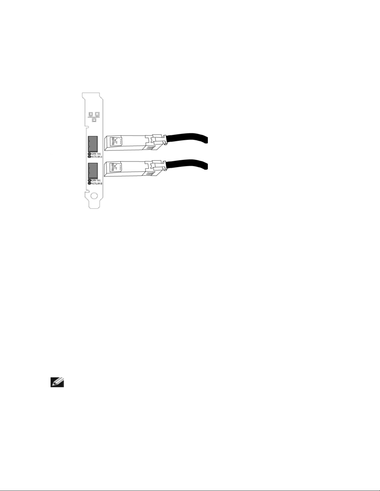
Connect the Direct Attach Cable
Insert the Direct Attach network cable as shown below.
Type of cabling:
l 40 Gigabit Ethernet over SFP+ Direct Attached Cable (Twinaxial)
l Length is 7 meters max.
l 10 Gigabit Ethernet over SFP+ Direct Attached Cable (Twinaxial)
l Length is 10 meters max.
PCI Hot Plug Support
Most Intel® Ethernet Server Adapters are enabled for use in selected servers equipped with Hot Plug support.
Exceptions: Intel Gigabit Quad Port Server adapters do not support Hot Plug operations.
If you replace an adapter in a Hot Plug slot, do not place the removed adapter back into the same network until
the server has rebooted (unless you return it to the same slot and same team as before). This prevents a
conflict in having two of the same Ethernet addresses on the same network.
The system will require a reboot if you
l Change the primary adapter designator.
l Add a new adapter to an existing team and make the new adapter the primary adapter.
l Remove the primary adapter from the system and replace it with a different type of adapter.
NOTE: To replace an existing SLA-teamed adapter in a Hot Plug slot, first unplug the adapter
cable. When the adapter is replaced, reconnect the cable.
PCI Hot Plug Support for Microsoft* Windows* Operating Systems
Intel® network adapters are enabled for use in selected servers equipped with PCI Hot Plug support and
runningMicrosoft* Windows* operating systems. For more information on setting up and using PCI Hot Plug
support in your server, see your hardware and/or Hot Plug support documentation for details. PCI Hot Plug
Page 26

only works when you hot plug an identical Intel network adapter.
NOTES:
l The MAC address and driver from the removed adapter will be used by the replacement
adapter unless you remove the adapter from the team and add it back in. If you do not
remove and restore the replacement adapter from the team, and the original adapter is used
elsewhere on your network, a MAC address conflict will occur.
l For SLA teams, ensure that the replacement NIC is a member of the team before connecting
it to the switch.
Page 27

Microsoft* Windows* Installation and Configuration
Installing Windows Drivers and Software
NOTE: To successfully install or uninstall the drivers or software, you must have administrative
privileges on the computer completing installation.
Install the Drivers
NOTE: This will update the drivers for all supported Intel® network adapters in your system.
Before installing or updating the drivers, insert your adapter(s) in the computer and plug in the network cable.
When Windows discovers the new adapter, it attempts to find an acceptable Windows driver already installed
with the operating system.
If found, the driver is installed without any user intervention. If Windows cannot find the driver, the Found New
Hardware Wizard window is displayed.
Regardless of whether Windows finds the driver, it is recommended that you follow the procedure below to
install the driver. Drivers for all Intel adapters supported by this software release are installed.
1. Download the latest drivers from the support website and transfer them to the system.
2. If the Found New Hardware Wizard screen is displayed, click Cancel.
3. Start the autorun located in the downloaded the software package. The autorun may automatically start
after you have extracted the files.
4. Click Install Drivers and Software.
5. Follow the instructions in the install wizard.
NOTE: Intel® PROSet is installed by default when you install the device drivers.
Installing the Base Driver and Intel® PROSet on Nano Server
Driver Installation
NOTE: Installing drivers requires administrator rights to the operating system.
To install drivers on Microsoft* Windows Server* Nano Server:
1. Identify which drivers to inject into the operating system.
2. Create a directory from which to install the drivers. For example, C:\Nano\Drivers
3. Copy the appropriate drivers for the operating system and hardware. For example, "copy
D:\PROXGB\Winx64\NDIS65\*.* c:\Nano\Drivers /y"
4. If you are using the New-NanoServerImage module, use the above path for the -DriversPath parameter. For example, "New-NanoServerImage ...-DriversPath C:\Nano\Drivers"
5. If you are using DISM.exe as well, use the above path for the /AddDriver parameter. For example,
"DISM .../Add-Driver C:\Nano\Drivers"
Page 28

Intel PROSet Installation
To install Intel PROSet on Microsoft* Windows Server* Nano Server:
1. Use the New-NanoServerImage cmdlet to add the PROSetNS.zip file from the
.\Disk\APPS\PROSETDX\NanoServer directory to your -CopyPath parameter.
2. Append the NanoSetup.ps1 file (located in the same directory) to your -SetupCompleteCommands
parameter.
For example:
New-NanoServerImage ...
-CopyPath "<PATH>\PROSetNS.zip", "<PATH>\NanoSetup.ps1" `
-SetupCompleteCommands "PowerShell ""C:\NanoSetup.ps1"""
See the link below for more information on deploying a Nano Server image and using the cmdlet:
https://msdn.microsoft.com/en-us/library/mt126167.aspx
Installing Intel PROSet
Intel PROSet for Windows Device Manager is an advanced configuration utility that incorporates additional
configuration and diagnostic features into the device manager.
NOTES:
l You must install Intel® PROSet for Windows Device Manager if you want to use Intel® ANS
teams or VLANs.
l Intel PROSet for Windows Device Manager is installed by default when you install the
device drivers. For information on usage, see Using Intel® PROSet for Windows Device
Manager.
Intel PROSet for Windows Device Manager is installed with the same process used to install drivers.
NOTES:
l You must have administrator rights to install or use Intel PROSet for Windows Device
Manager.
l Upgrading PROSet for Windows Device Manager may take a few minutes.
1. On the autorun, click Install Base Drivers and Software.
NOTE: You can also run setup64.exe from the files downloaded from Customer Support.
2. Proceed with the installation wizard until the Custom Setup page appears.
3. Select the features to install.
4. Follow the instructions to complete the installation.
If Intel PROSet for Windows Device Manager was installed without ANS support, you can install support by
clicking Install Base Drivers and Software on the autorun, or running setup64.exe, and then selecting the
Modify option when prompted. From the Intel® Network Connections window, select Advanced Network
Services then click Next to continue with the installation wizard.
Page 29

Command Line Installation for Base Drivers and Intel® PROSet
Driver Installation
The driver install utility DxSetup.exe allows unattended installation of drivers from a command line.
NOTES:
l Intel® 10GbE Network Adapters do not support unattended driver install-
ation.
l Intel PROSet cannot be installed with msiexec.exe. You must use
DxSetup.exe.
These utilities can be used to install the base driver, intermediate driver, and all management applications for
supported devices.
DxSetup.exe Command Line Options
By setting the parameters in the command line, you can enable and disable management applications. If
parameters are not specified, only existing components are updated.
DxSetup.exe supports the following command line parameters:
Parameter Definition
BD Base Driver
"0", do not install the base driver.
"1", install the base driver (default).
ANS Advanced Network Services
"0", do not install ANS (default). If ANS is already installed, it will be uninstalled.
"1", install ANS. The ANS property requires DMIX=1.
NOTE: If the ANS parameter is set to ANS=1, both Intel PROSet and ANS
will be installed.
DMIX PROSet for Windows Device Manager
"0", do not install Intel PROSet feature (default). If the Intel PROSet feature is already
installed, it will be uninstalled.
"1", install Intel PROSet feature. The DMIX property requires BD=1.
NOTE: If DMIX=0, ANS will not be installed. If DMIX=0 and Intel PROSet,
ANS, and FCoE are already installed, Intel PROSet, ANS, and FCoE will be
uninstalled.
FCOE Fibre Channel over Ethernet
"0", do not install FCoE (default). If FCoE is already installed, it will be uninstalled.
"1", install FCoE. The FCoE property requires DMIX=1.
Page 30

Parameter Definition
NOTE: Even if FCOE=1 is passed, FCoE will not be installed if the operating
system and installed adapters do not support FCoE.
ISCSI iSCSI
"0", do not install iSCSI (default). If iSCSI is already installed, it will be uninstalled.
"1", install FCoE. The iSCSI property requires DMIX=1.
IWARP_
ROUTING
iWARProuting
"0", do not install iWARProuting.
"1", install iWARProuting.
IWARP_
FIREWALL
Installs the iWARPfirewall rule. For more information see iWARP(Internet Wide Area
RDMAProtocol) section.
"0", do not install iWARPfirewall rule.
"1", install iWARPfirewall rule. If "1"is selected, the following parameters are allowed
in addition to IWARP_FIREWALL.
l IWARP_FIREWALL_DOMAIN [0|1] - Applies firewall rule to corporate domains.
l IWARP_FIREWALL_PUBLIC [0|1] - Applies firewall rule to public networks
l IWARP_FIREWALL_PRIVATE [0|1] - Applies firewall rule to private networks
FORCE "0", check that the installed device supports a feature (FCOE, iSCSI) and only install
the feature if such a device is found.
"1", install the specified features regardless of the presence of supporting devices.
/q[r|n] /q --- silent install options
r Reduced GUI Install (only displays critical warning messages)
n Silent install
/l[i|w|e|a] /l --- log file option for PROSet installation. Following are log switches:
i log status messages.
w log non-fatal warnings.
e log error messages.
a log the start of all actions.
Page 31

Parameter Definition
/uninstall
/x
NOTES:
Uninstall Intel PROSet and drivers.
l You must include a space between parameters.
l If you specify a path for the log file, the path must exist. If you do not specify a complete
path, the install log will be created in the current directory.
l You do not need to specify default values. To install the base drivers, Intel PROSet, and
ANS, the following examples are equivalent:
DxSetup.exe
DxSetup.exe BD=1 DMIX=1 ANS=1
l The ANS property should only be set to ANS=1 if DMIX=1 is set. If DMIX=0 and ANS=1, the
ANS=1 is ignored and only the base driver will be installed.
l Even if FCOE=1 is passed, FCoE using DCB will not be installed if the operating system
and installed adapters do not support it. If FORCE=1 is also passed, FCoE will be installed if
the operating system supports it.
l Even if ISCSI=1 is passed, iSCSI using DCB will not be installed if the operating system
and installed adapters do not support it. If FORCE=1 is also passed, iSCSI will be installed if
the operating system supports it.
l Public properties are not case sensitive. No white space is allowed between characters. For
example:
DxSetup.exe /qn DMIX=1
Any white space in "DMIX=1" makes the setting invalid.
Command line install examples
Assume that DxSetup.exeis in the root directory of the CD, D:\.
1. How to install the base driver:
D:\DxSetup.exe DMIX=0 ANS=0
2. How to install the base driver using the LOG option:
D:\DxSetup.exe LOG=C:\installBD.log DMIX=0 ANS=0
3. How to install Intel PROSet and ANS silently:
D:\DxSetup.exe DMIX=1 ANS=1 /qn
4. How to install Intel PROSet without ANS silently:
D:\DxSetup.exe DMIX=1 ANS=0 /qn
Page 32

5. How to install components but deselect ANS:
D:\DxSetup.exe DMIX=1 ANS=0 /qn /liew C:\install.log
The /liew log option provides a log file for the Intel PROSet installation.
NOTE: To install teaming and VLAN support on a system that has adapter base drivers and Intel
PROSet for Windows Device Manager installed, type the command line D:\DxSetup.exe
ANS=1.
Modify and Upgrade
You can use DxSetup.exeto modify or upgrade your drivers and software. If a feature is already installed, the
public property for that feature will default to 1 and if a feature is not installed, the public property for that
feature will default to 0. Running DxSetup.exewithout specifying properties will upgrade all installed software.
You can remove installed software (except for base drivers) by setting the property to 0. If you uninstall
PROSet (DMIX=0), all features that rely on PROSet will also be removed.
Windows Server Core
Command Line Options
SetupBD.exe supports the following command line switches.
NOTE: You must include a space between switches.
Switch Description
/s silent install
/r force reboot (must be used with the /s switch)
/nr no reboot (must be used with the /s switch. This switch is ignored if it is included with the /r
switch)
Examples:
Option Description
SetupBD Installs and/or updates the driver(s) and displays the GUI.
SetupBD /s Installs and/or updates the driver(s) silently.
SetupBD /s /r Installs and/or updates the driver(s) silently and forces a reboot.
SetupBD /s /r /nr Installs and/or updates the driver(s) silently and forces a reboot (/nr is ignored).
Other information
You can use the /r and /nr switches only with a silent install (i.e. with the "/s" option).
Page 33

Using Intel®PROSet for Windows* Device Manager
Intel® PROSet for Windows* Device Manager is an extension to the Windows Device Manager. When you
install the Intel PROSet software, additional tabs are automatically added to Device Manager.
NOTES:
l You must have administrator rights to install or use Intel PROSet for Windows Device Man-
ager.
l Intel PROSet for Windows Device Manager and the IntelNetCmdlets module for
WindowsPowerShell* require the latest driver and software package for your Intel Ethernet
devices. Please download the most recent driver and software package for your operating
system from www.intel.com.
l On recent operating systems, older hardware may not support Intel PROSet for Windows
Device Manager and the IntelNetCmdlets module for WindowsPowerShell. In this case, the
Intel PROSet tabs may not be displayed in the Windows Device Manager user interface, and
the IntelNetCmdlets may display an error message stating that the device does not have an
Intel driver installed.
Changing Intel PROSet Settings Under Windows Server Core
You can use the Intel NetCmdlets for Microsoft*Windows PowerShell* to change most Intel PROSet settings
under Windows Server Core. Please refer to the aboutIntelNetCmdlets.hlp.txt help file.
For iSCSICrash Dump configuration, use the Intel NetCmdlets for Microsoft*Windows PowerShell* and refer
to the aboutIntelNetCmdlets.help.txt help file.
NOTE: Support for the Intel PROSet command line utilities (prosetcl.exe and crashdmp.exe) has
been removed, and is no longer installed. This functionality has been replaced by the Intel
Netcmdlets for Microsoft* Windows PowerShell*. Please transition all of your scripts and
processes to use the Intel Netcmdlets for Microsoft Windows PowerShell.
Compatibility Notes
The following devices do not support Intel PROSet for Windows Device Manager
l Intel® 82552 10/100 Network Connection
l Intel® 82567V-3 Gigabit Network Connection
l Intel® X552 10G Ethernet devices
l Intel® X553 10G Ethernet devices
l Any platform with a System on a Chip (SoC) processor that includes either a server controller (des-
ignated by an initial X, such as X552) or both a server and client controller (designated by an initial I,
such as I218)
l Devices based on the Intel® Ethernet Controller X722
Link Speed tab
The Link Speed tab allows you to change the adapter's speed and duplex setting, run diagnostics, and use
the identify adapter feature.
Page 34

Setting Speed and Duplex
Overview
The Link Speed and Duplex setting lets you choose how the adapter sends and receives data packets over
the network.
In the default mode, an Intel network adapter using copper connections will attempt to auto-negotiate with its
link partner to determine the best setting. If the adapter cannot establish link with the link partner using autonegotiation, you may need to manually configure the adapter and link partner to the identical setting to
establish link and pass packets. This should only be needed when attempting to link with an older switch that
does not support auto-negotiation or one that has been forced to a specific speed or duplex mode.
Auto-negotiation is disabled by selecting a discrete speed and duplex mode in the adapter properties sheet.
NOTES:
l When an adapter is running in NPar mode, Speed settings are limited to the root partition of
each port.
l Fiber-based adapters operate only in full duplex at their native speed.
The settings available when auto-negotiation is disabled are:
l 40 Gbps full duplex (requires a full duplex link partner set to full duplex). The adapter can send and
receive packets at the same time.
l 10 Gbps full duplex (requires a full duplex link partner set to full duplex). The adapter can send and
receive packets at the same time.
l 1 Gbps full duplex (requires a full duplex link partner set to full duplex). The adapter can send and
receive packets at the same time. You must set this mode manually (see below).
l 10 Mbps or 100 Mbps full duplex (requires a link partner set to full duplex). The adapter can send
and receive packets at the same time. You must set this mode manually (see below).
l 10 Mbps or 100 Mbps half duplex (requires a link partner set to half duplex). The adapter performs
one operation at a time; it either sends or receives. You must set this mode manually (see below).
Your link partner must match the setting you choose.
NOTES:
l Although some adapter property sheets (driver property settings) list 10 Mbps and 100 Mbps
in full or half duplex as options, using those settings is not recommended.
l Only experienced network administrators should force speed and duplex manually.
l You cannot change the speed or duplex of Intel adapters that use fiber cabling.
Intel 10 Gigabit adapters that support 1 gigabit speed allow you to configure the speed setting. If this option is
not present, your adapter only runs at its native speed.
If the adapter cannot establish link with the gigabit link partner using auto-negotiation, set the adapter to 1
Gbps Full duplex.
Intel 10 gigabit fiber-based adapters and SFP direct-attach devices operate only in full duplex, and only at their
native speed. Multi-speed 10 gigabit SFP+ fiber modules support full duplex at 10 Gbps and 1 Gbps.
Auto-negotiation and Auto-Try are not supported on devices based on the Intel®Ethernet Connection X552
controller and Intel®Ethernet Connection X553 controller.
Page 35

Manually Configuring Duplex and Speed Settings
Configuration is specific to your operating system driver. To set a specific Link Speed and Duplex mode, refer
to the section below that corresponds to your operating system.
CAUTION: The settings at the switch must always match the adapter settings. Adapter performance may suffer, or your adapter might not operate correctly if you configure the adapter
differently from your switch.
The default setting is for auto-negotiation to be enabled. Only change this setting to match your link partner's
speed and duplex setting if you are having trouble connecting.
1. In Windows Device Manager, double-click the adapter you want to configure.
2. On the Link Speed tab, select a speed and duplex option from the Speed and Duplex drop-down
menu.
3. Click OK.
More specific instructions are available in the Intel PROSet help.
Advanced Tab
The settings listed on Intel PROSet for Windows Device Manager's Advanced tab allow you to customize
how the adapter handles QoS packet tagging, Jumbo Packets, Offloading, and other capabilities. Some of the
following features might not be available depending on the operating system you are running, the specific
adapters installed, and the specific platform you are using.
Adaptive Inter-Frame Spacing
Compensates for excessive Ethernet packet collisions on the network.
The default setting works best for most computers and networks. By enabling this feature, the network
adapter dynamically adapts to the network traffic conditions. However, in some rare cases you might obtain
better performance by disabling this feature. This setting forces a static gap between packets.
Default Disabled
Range l Enabled
l Disabled
Direct Memory Access (DMA) Coalescing
DMA (Direct Memory Access) allows the network device to move packet data directly to the system's
memory, reducing CPU utilization. However, the frequency and random intervals at which packets arrive do
not allow the system to enter a lower power state. DMA Coalescing allows the NIC to collect packets before it
initiates a DMA event. This may increase network latency but also increases the chances that the system will
consume less energy. Adapters and network devices based on the Intel® Ethernet Controller I350 (and later
controllers) support DMA Coalescing.
Higher DMA Coalescing values result in more energy saved but may increase your system's network latency.
If you enable DMA Coalescing, you should also set the Interrupt Moderation Rate to 'Minimal'. This minimizes
the latency impact imposed by DMA Coalescing and results in better peak network throughput performance.
You must enable DMA Coalescing on all active ports in the system. You may not gain any energy savings if it
Page 36

is enabled only on some of the ports in your system. There are also several BIOS, platform, and application
settings that will affect your potential energy savings. A white paper containing information on how to best
configure your platform is available on the Intel website.
Flow Control
Enables adapters to more effectively regulate traffic. Adapters generate flow control frames when their
receive queues reach a pre-defined limit. Generating flow control frames signals the transmitter to slow
transmission. Adapters respond to flow control frames by pausing packet transmission for the time specified
in the flow control frame.
By enabling adapters to adjust packet transmission, flow control helps prevent dropped packets.
NOTES:
l For adapters to benefit from this feature, link partners must support flow control frames.
l When an adapter is running in NPar mode, Flow Control is limited to the root partition of
each port.
Default RX & TX Enabled
Range l Disabled
l RX Enabled
l TX Enabled
l RX & TX Enabled
Gigabit Master Slave Mode
Determines whether the adapter or link partner is designated as the master. The other device is designated as
the slave. By default, the IEEE 802.3ab specification defines how conflicts are handled. Multi-port devices
such as switches have higher priority over single port devices and are assigned as the master. If both devices
are multi-port devices, the one with higher seed bits becomes the master. This default setting is called
"Hardware Default."
NOTE: In most scenarios, it is recommended to keep the default value of this feature.
Setting this to either "Force Master Mode" or "Force Slave Mode" overrides the hardware default.
Default Auto Detect
Range l Force Master Mode
l Force Slave Mode
l Auto Detect
NOTE: Some multi-port devices may be forced to Master Mode. If the adapter is connected to such
a device and is configured to "Force Master Mode," link is not established.
Page 37

Interrupt Moderation Rate
Sets the Interrupt Throttle Rate (ITR). This setting moderates the rate at which Transmit and Receive
interrupts are generated.
When an event such as packet receiving occurs, the adapter generates an interrupt. The interrupt interrupts
the CPU and any application running at the time, and calls on the driver to handle the packet. At greater link
speeds, more interrupts are created, and CPU rates also increase. This results in poor system performance.
When you use a higher ITR setting, the interrupt rate is lower and the result is better CPU performance.
NOTE: A higher ITR rate also means that the driver has more latency in handling packets. If the
adapter is handling many small packets, it is better to lower the ITR so that the driver can be more
responsive to incoming and outgoing packets.
Altering this setting may improve traffic throughput for certain network and system configurations, however
the default setting is optimal for common network and system configurations. Do not change this setting
without verifying that the desired change will have a positive effect on network performance.
Default Adaptive
Range l Adaptive
l Extreme
l High
l Medium
l Low
l Minimal
l Off
IPv4 Checksum Offload
This allows the adapter to compute the IPv4 checksum of incoming and outgoing packets. This feature
enhances IPv4 receive and transmit performance and reduces CPU utilization.
With Offloading off, the operating system verifies the IPv4 checksum.
With Offloading on, the adapter completes the verification for the operating system.
Default RX & TX Enabled
Range l Disabled
l RX Enabled
l TX Enabled
l RX & TX Enabled
Jumbo Frames
Enables or disables Jumbo Packet capability. The standard Ethernet frame size about 1514 bytes, while
Jumbo Packets are larger than this. Jumbo Packets can increase throughput and decrease CPU utilization.
However, additional latency may be introduced.
Page 38

Enable Jumbo Packets only if ALL devices across the network support them and are configured to use the
same frame size. When setting up Jumbo Packets on other network devices, be aware that network devices
calculate Jumbo Packet sizes differently. Some devices include the frame size in the header information
while others do not. Intel adapters do not include frame size in the header information.
Jumbo Packets can be implemented simultaneously with VLANs and teaming. If a team contains one or more
non-Intel adapters, the Jumbo Packets feature for the team is not supported. Before adding a non-Intel adapter
to a team, make sure that you disable Jumbo Packets for all non-Intel adapters using the software shipped
with the adapter.
Restrictions
l Jumbo frames are not supported in multi-vendor team configurations.
l Supported protocols are limited to IP (TCP, UDP).
l Jumbo frames require compatible switch connections that forward Jumbo Frames. Contact your
switch vendor for more information.
l When standard-sized Ethernet frames (64 to 1518 bytes) are used, there is no benefit to configuring
Jumbo Frames.
l The Jumbo Packets setting on the switch must be set to at least 8 bytes larger than the adapter setting
for Microsoft Windows operating systems, and at least 22 bytes larger for all other operating systems.
Default Disabled
Range Disabled (1514), 4088, or 9014 bytes. (Set the switch 4 bytes higher for CRC, plus 4 bytes if
using VLANs.)
NOTES:
l Jumbo Packets are supported at 10 Gbps and 1 Gbps only. Using Jumbo Packets at 10 or
100 Mbps may result in poor performance or loss of link.
l End-to-end hardware must support this capability; otherwise, packets will be dropped.
l Intel adapters that support Jumbo Packets have a frame size limit of 9238 bytes, with a
corresponding MTU size limit of 9216 bytes.
Large Send Offload (IPv4 and IPv6)
Sets the adapter to offload the task of segmenting TCP messages into valid Ethernet frames. The maximum
frame size limit for large send offload is set to 64,000 bytes.
Since the adapter hardware is able to complete data segmentation much faster than operating system
software, this feature may improve transmission performance. In addition, the adapter uses fewer CPU
resources.
Default Enabled
Range l Enabled
l Disabled
Page 39

Locally Administered Address
Overrides the initial MAC address with a user-assigned MAC address. To enter a new network address, type
a 12-digit hexadecimal number in this box.
Default None
Range 0000 0000 0001 - FFFF FFFF FFFD
Exceptions:
l Do not use a multicast address (Least Significant Bit of the high byte = 1). For
example, in the address 0Y123456789A, "Y" cannot be an odd number. (Y must be 0,
2, 4, 6, 8, A, C, or E.)
l Do not use all zeros or all Fs.
If you do not enter an address, the address is the original network address of the adapter.
For example,
Multicast: 0123 4567 8999 Broadcast: FFFF FFFF FFFF
Unicast (legal): 0070 4567 8999
NOTE: In a team, Intel PROSet uses either:
l The primary adapter's permanent MAC address if the team does not have an LAA con-
figured, or
l The team's LAA if the team has an LAA configured.
Intel PROSet does not use an adapter's LAA if the adapter is the primary adapter in a team and the
team has an LAA.
Log Link State Event
This setting is used to enable/disable the logging of link state changes. If enabled, a link up change event or a
link down change event generates a message that is displayed in the system event logger. This message
contains the link's speed and duplex. Administrators view the event message from the system event log.
The following events are logged.
l The link is up.
l The link is down.
l Mismatch in duplex.
l Spanning Tree Protocol detected.
Default Enabled
Range Enabled, Disabled
Page 40

Low Latency Interrupts
LLI enables the network device to bypass the configured interrupt moderation scheme based on the type of
data being received. It configures which arriving TCP packets trigger an immediate interrupt, enabling the
system to handle the packet more quickly. Reduced data latency enables some applications to gain faster
access to network data.
NOTE: When LLI is enabled, system CPU utilization may increase.
LLI can be used for data packets containing a TCP PSH flag in the header or for specified TCP ports.
l Packets with TCP PSH Flag - Any incoming packet with the TCP PSH flag will trigger an immediate
interrupt. The PSH flag is set by the sending device.
l TCP Ports - Every packet received on the specified ports will trigger an immediate interrupt. Up to
eight ports may be specified.
Default Disabled
Range l Disabled
l PSH Flag-Based
l Port-Based
Network Virtualization using Generic Routing Encapsulation (NVGRE)
Network Virtualization using Generic Routing Encapsulation (NVGRE) increases the efficient routing of
network traffic within a virtualized or cloud environment. Some Intel® Ethernet Network devices perform
Network Virtualization using Generic Routing Encapsulation (NVGRE) processing, offloading it from the
operating system. This reduces CPU utilization.
Performance Options
Performance Profile
Performance Profiles are supported on Intel® 10GbE adapters and allow you to quickly optimize the
performance of your Intel® Ethernet Adapter. Selecting a performance profile will automatically adjust some
Advanced Settings to their optimum setting for the selected application. For example, a standard server has
optimal performance with only two RSS (Receive-Side Scaling) queues, but a web server requires more RSS
queues for better scalability.
You must install Intel® PROSet for Windows Device Manager to use Performance profiles. Profiles are
selected on the Advanced tab of the adapter's property sheet.
Profiles l Standard Server – This profile is optimized for typical servers.
l Web Server – This profile is optimized for IIS and HTTP-based web servers.
l Virtualization Server – This profile is optimized for Microsoft’s Hyper-V virtualization
environment.
l Storage Server – This profile is optimized for Fibre Channel over Ethernet or for
iSCSI over DCB performance. Selecting this profile will disable SR-IOV and VMQ.
l Storage + Virtualization – This profile is optimized for a combination of storage and
virtualization requirements.
Page 41

l Low Latency – This profile is optimized to minimize network latency.
NOTES:
l Not all options are available on all adapter/operating system combinations.
l If you have selected the Virtualization Server profile or the Storage + Virtualization profile,
and you uninstall the Hyper-V role, you should select a new profile.
Teaming Considerations
When you create a team with all members of the team supporting Performance Profiles, you will be asked
which profile to use at the time of team creation. The profile will be synchronized across the team. If there is
not a profile that is supported by all team members then the only option will be Use Current Settings. The team
will be created normally. Adding an adapter to an existing team works in much the same way.
If you attempt to team an adapter that supports performance profiles with an adapter that doesn't, the profile
on the supporting adapter will be set to Custom Settings and the team will be created normally.
Priority & VLAN Tagging
Enables the adapter to offload the insertion and removal of priority and VLAN tags for transmit and receive.
Default Priority & VLAN Enabled
Range l Priority & VLAN Disabled
l Priority Enabled
l VLAN Enabled
l Priority & VLAN Enabled
Quality of Service
Quality of Service (QoS) allows the adapter to send and receive IEEE 802.3ac tagged frames. 802.3ac tagged
frames include 802.1p priority-tagged frames and 802.1Q VLAN-tagged frames. In order to implement QoS,
the adapter must be connected to a switch that supports and is configured for QoS. Priority-tagged frames
allow programs that deal with real-time events to make the most efficient use of network bandwidth. High
priority packets are processed before lower priority packets.
Tagging is enabled and disabled in Microsoft* Windows* Server* using the "QoS Packet Tagging" field in the
Advanced tab in Intel® PROSet. For other versions of the Windows operating system, tagging is enabled
using the "Priority/VLAN Tagging" setting on the Advanced tab in Intel® PROSet.
Once QoS is enabled in Intel PROSet, you can specify levels of priority based on IEEE 802.1p/802.1Q frame
tagging.
The supported operating systems, including Microsoft* Windows Server*, have a utility for 802.1p packet
prioritization. For more information, see the Windows system help and Microsoft's knowledge base.
NOTE: The first generation Intel® PRO/1000 Gigabit Server Adapter (PWLA 8490) does not
support QoS frame tagging.
Page 42

Receive Buffers
Defines the number of Receive Buffers, which are data segments. They are allocated in the host memory and
used to store the received packets. Each received packet requires at least one Receive Buffer, and each
buffer uses 2KB of memory.
You might choose to increase the number of Receive Buffers if you notice a significant decrease in the
performance of received traffic. If receive performance is not an issue, use the default setting appropriate to
the adapter.
Default 512, for the 10 Gigabit Server Adapters.
256, for all other adapters depending on the features selected.
Range 128-4096, in intervals of 64, for the 10 Gigabit Server Adapters.
80-2048, in intervals of 8, for all other adapters.
Recommended Value Teamed adapter: 256
Using IPSec and/or multiple features: 352
Receive Side Scaling
When Receive Side Scaling (RSS) is enabled, all of the receive data processing for a particular TCP
connection is shared across multiple processors or processor cores. Without RSS all of the processing is
performed by a single processor, resulting in less efficient system cache utilization. RSS can be enabled for a
LAN or for FCoE. In the first case, it is called "LAN RSS". In the second, it is called "FCoE RSS".
LAN RSS
LAN RSS applies to a particular TCP connection.
NOTE: This setting has no effect if your system has only one processing unit.
LAN RSS Configuration
RSS is enabled on the Advanced tab of the adapter property sheet. If your adapter does not support RSS, or
if the SNP or SP2 is not installed, the RSS setting will not be displayed. If RSS is supported in your system
environment, the following will be displayed:
l Port NUMA Node. This is the NUMA node number of a device.
l Starting RSS CPU. This setting allows you to set the p referred starting RSS processor. Change this
setting if the current processor is dedicated to other processes. The setting range is from 0 to the number of logical CPUs - 1. In Server 2008 R2, RSS will only use CPUs in group 0 (CPUs 0 through 63).
l Max number of RSS CPU. This setting allows you to set the maximum number of CPUs assigned to
an adapter and is primarily used in a Hyper-V environment. By decreasing this setting in a Hyper-V
environment, the total number of interrupts is reduced which lowers CPU utilization. The default is 8 for
Gigabit adapters and 16 for 10 Gigabit adapters.
l Preferred NUMA Node. This setting allows you to choose the preferred NUMA (Non-Uniform
Memory Access) node to be used for memory allocations made by the network adapter. In addition the
system will attempt to use the CPUs from the preferred NUMA node first for the purposes of RSS. On
NUMA platforms, memory access latency is dependent on the memory location. Allocation of memory
from the closest node helps improve performance. The Windows Task Manager shows the NUMA
Page 43

Node ID for each processor.
NOTES:
l This setting only affects NUMA systems. It will have no effect on non-NUMA sys-
tems.
l Choosing a value greater than the number of NUMA nodes present in the system
selects the NUMA node closest to the device.
l Receive Side Scaling Queues. This setting configures the number of RSS queues, which determine
the space to buffer transactions between the network adapter and CPU(s).
Default 2 queues for the Intel® 10 Gigabit Server Adapters
Range l 1 queue is used when low CPU utilization is required.
l 2 queues are used when good throughput and low CPU utilization are required.
l 4 queues are used for applications that demand maximum throughput and
transactions per second.
l 8 and 16 queues are supported on the Intel® 82598-based and 82599-based
adapters.
NOTES:
l The 8 and 16 queues are only available when PROSet for
Windows Device Manager is installed. If PROSet is not
installed, only 4 queues are available.
l Using 8 or more queues will require the system to reboot.
NOTE: Not all settings are available on all adapters.
LAN RSS and Teaming
l If RSS is not enabled for all adapters in a team, RSS will be disabled for the team.
l If an adapter that does not support RSS is added to a team, RSS will be disabled for the team.
l If you create a multi-vendor team, you must manually verify that the RSS settings for all adapters in the
team are the same.
FCoE RSS
If FCoE is installed, FCoE RSS is enabled and applies to FCoE receive processing that is shared across
processor cores.
FCoE RSS Configuration
If your adapter supports FCoE RSS, the following configuration settings can be viewed and changed on the
base driver Advanced Performance tab:
l FCoE NUMA Node Count. This setting specifies the number of consecutive NUMA Nodes where
the allocated FCoE queues will be evenly distributed.
l FCoE Starting NUMA Node. This setting specifies the NUMA node representing the first node within
the FCoE NUMA Node Count.
Page 44

l FCoE Starting Core Offset. This setting specifies the offset to the first NUMA Node CPU core that
will be assigned to FCoE queue.
l FCoE Port NUMA Node. This setting is an indication from the platform of the optimal closest NUMA
Node to the physical port, if available. This setting is read-only and cannot be configured.
Performance Tuning
The Intel Network Controller provides a new set of advanced FCoE performance tuning options. These
options will direct how FCoE transmit/receive queues are allocated in NUMA platforms. Specifically, they
direct what target set of NUMA node CPUs can be selected from to assign individual queue affinity. Selecting
a specific CPU has two main effects:
l It sets the desired interrupt location for processing queue packet indications.
l It sets the relative locality of the queue to available memory.
As indicated, these are intended as advanced tuning options for those platform managers attempting to
maximize system performance. They are generally expected to be used to maximize performance for multiport platform configurations. Since all ports share the same default installation directives (the .inf file, etc.),
the FCoE queues for every port will be associated with the same set of NUMA CPUs which may result in
CPU contention.
The software exporting these tuning options defines a NUMA Node to be equivalent to an individual processor
(socket). Platform ACPI information presented by the BIOS to the operating system helps define the relation
of PCI devices to individual processors. However, this detail is not currently reliably provided in all platforms.
Therefore, using the tuning options may produce unexpected results. Consistent or predictable results when
using the performance options cannot be guaranteed.
The performance tuning options are listed in the LAN RSS Configuration section.
Example 1: A platform with two physical sockets, each socket processor providing 8 core CPUs (16 when
hyper threading is enabled), and a dual port Intel adapter with FCoE enabled.
By default 8 FCoE queues will be allocated per NIC port. Also, by default the first (non-hyper thread) CPU
cores of the first processor will be assigned affinity to these queues resulting in the allocation model pictured
below. In this scenario, both ports would be competing for CPU cycles from the same set of CPUs on socket
0.
Socket Queue to CPU Allocation
Using performance tuning options, the association of the FCoE queues for the second port can be directed to
a different non-competing set of CPU cores. The following settings would direct SW to use CPUs on the other
processor socket:
l FCoE NUMA Node Count = 1: Assign queues to cores from a single NUMA node (or processor
socket).
l FCoE Starting NUMA Node = 1: Use CPU cores from the second NUMA node (or processor socket) in
the system.
l FCoE Starting Core Offset = 0: SW will start at the first CPU core of the NUMA node (or processor
socket).
The following settings would direct SW to use a different set of CPUs on the same processor socket. This
assumes a processor that supports 16 non-hyperthreading cores.
Page 45

l FCoE NUMA Node Count = 1
l FCoE Starting NUMA Node = 0
l FCoE Starting Core Offset = 8
Example 2: Using one or more ports with queues allocated across multiple NUMA nodes. In this case, for
each NIC port the FCoE NUMA Node Count is set to that number of NUMA nodes. By default the queues will
be allocated evenly from each NUMA node:
l FCoE NUMA Node Count = 2
l FCoE Starting NUMA Node = 0
l FCoE Starting Core Offset = 0
Example 3: The display shows FCoE Port NUMA Node setting is 2 for a given adapter port. This is a readonly indication from SW that the optimal nearest NUMA node to the PCI device is the third logical NUMA
node in the system. By default SW has allocated that port's queues to NUMA node 0. The following settings
would direct SW to use CPUs on the optimal processor socket:
l FCoE NUMA Node Count = 1
l FCoE Starting NUMA Node = 2
l FCoE Starting Core Offset = 0
This example highlights the fact that platform architectures can vary in the number of PCI buses and where
they are attached. The figures below show two simplified platform architectures. The first is the older common
FSB style architecture in which multiple CPUs share access to a single MCH and/or ESB that provides PCI
bus and memory connectivity. The second is a more recent architecture in which multiple CPU processors
are interconnected via QPI, and each processor itself supports integrated MCH and PCI connectivity directly.
There is a perceived advantage in keeping the allocation of port objects, such as queues, as close as possible
to the NUMA node or collection of CPUs where it would most likely be accessed. If the port queues are using
CPUs and memory from one socket when the PCI device is actually hanging off of another socket, the result
may be undesirable QPI processor-to-processor bus bandwidth being consumed. It is important to understand
the platform architecture when using these performance options.
Shared Single Root PCI/Memory Architecture
Page 46

Distributed Multi-Root PCI/Memory Architecture
Example 4: The number of available NUMA node CPUs is not sufficient for queue allocation. If your platform
has a processor that does not support an even power of 2 CPUs (for example, it supports 6 cores), then during
queue allocation if SW runs out of CPUs on one socket it will by default reduce the number of queues to a
power of 2 until allocation is achieved. For example, if there is a 6 core processor being used, the SW will only
allocate 4 FCoE queues if there only a single NUMA node. If there are multiple NUMA nodes, the NUMA node
count can be changed to a value greater than or equal to 2 in order to have all 8 queues created.
Determinin g Active Queue Location
The user of these performance options will want to determine the affinity of FCoE queues to CPUs in order to
verify their actual effect on queue allocation. This is easily done by using a small packet workload and an I/O
application such as IoMeter. IoMeter monitors the CPU utilization of each CPU using the built-in performance
monitor provided by the operating system. The CPUs supporting the queue activity should stand out. They
should be the first non-hyper thread CPUs available on the processor unless the allocation is specifically
directed to be shifted via the performance options discussed above.
To make the locality of the FCoE queues even more obvious, the application affinity can be assigned to an
isolated set of CPUs on the same or another processor socket. For example, the IoMeter application can be
set to run only on a finite number of hyper thread CPUs on any processor. If the performance options have
been set to direct queue allocation on a specific NUMA node, the application affinity can be set to a different
NUMA node. The FCoE queues should not move and the activity should remain on those CPUs even though
the application CPU activity moves to the other processor CPUs selected.
SR-IOV (Single Root I/O Virtualization)
SR-IOV lets a single network port appear to be several virtual functions in a virtualized environment. If you
have an SR-IOV capable NIC, each port on that NIC can assign a virtual function to several guest partitions.
The virtual functions bypass the Virtual Machine Manager (VMM), allowing packet data to move directly to a
guest partition's memory, resulting in higher throughput and lower CPU utilization. SR-IOV also allows you to
move packet data directly to a guest partition's memory. SR-IOV support was added in Microsoft Windows
Server 2012. See your operating system documentation for system requirements.
For devices that support it, SR-IOV is enabled in the host partition on the adapter's Device Manager property
sheet, under Virtualization on the Advanced Tab. Some devices may need to have SR-IOV enabled in a
preboot environment.
Page 47

NOTES:
l Configuring SR-IOV for improved network security: In a virtualized envir-
onment, on Intel® Server Adapters that support SR-IOV, the virtual function
(VF) may be subject to malicious behavior. Software-generated frames are not
expected and can throttle traffic between the host and the virtual switch, reducing performance. To resolve this issue, configure all SR-IOV enabled ports
for VLAN tagging. This configuration allows unexpected, and potentially mali-
cious, frames to be dropped.
l You must enable VMQ for SR-IOV to function.
l SR-IOV is not supported with ANS teams.
l VMWare ESXi does not support SR-IOV on 1GbE ports.
TCP Checksum Offload (IPv4 and IPv6)
Allows the adapter to verify the TCP checksum of incoming packets and compute the TCP checksum of
outgoing packets. This feature enhances receive and transmit performance and reduces CPU utilization.
With Offloading off, the operating system verifies the TCP checksum.
With Offloading on, the adapter completes the verification for the operating system.
Default RX & TX Enabled
Range l Disabled
l RX Enabled
l TX Enabled
l RX & TX Enabled
TCP/IP Offloading Options
Thermal Monitoring
Adapters and network controllers based on the Intel® Ethernet Controller I350 (and later controllers) can
display temperature data and automatically reduce the link speed if the controller temperature gets too hot.
NOTE: This feature is enabled and configured by the equipment manufacturer. It is not available on
all adapters and network controllers. There are no user configurable settings.
Monitoring and Reporting
Temperature information is displayed on the Link tab in Intel® PROSet for Windows* Device Manger. There
are three possible conditions:
l Temperature: Normal
Indicates normal operation.
l Temperature: Overheated, Link Reduced
Indicates that the device has reduced link speed to lower power consumption and heat.
l Temperature: Overheated, Adapter Stopped
Indicates that the device is too hot and has stopped passing traffic so it is not damaged.
Page 48

If either of the overheated events occur, the device driver writes a message to the system event log.
Transmit Buffers
Defines the number of Transmit Buffers, which are data segments that enable the adapter to track transmit
packets in the system memory. Depending on the size of the packet, each transmit packet requires one or
more Transmit Buffers.
You might choose to increase the number of Transmit Buffers if you notice a possible problem with transmit
performance. Although increasing the number of Transmit Buffers can enhance transmit performance,
Transmit Buffers do consume system memory. If transmit performance is not an issue, use the default
setting. This default setting varies with the type of adapter.
View the Adapter Specifications topic for help identifying your adapter.
Default 512, depending on the requirements of the adapter
Range 128-16384, in intervals of 64, for 10 Gigabit Server Adapters.
80-2048, in intervals of 8, for all other adapters.
UDP Checksum Offload (IPv4 and IPv6)
Allows the adapter to verify the UDP checksum of incoming packets and compute the UDP checksum of
outgoing packets. This feature enhances receive and transmit performance and reduces CPU utilization.
With Offloading off, the operating system verifies the UDP checksum.
With Offloading on, the adapter completes the verification for the operating system.
Default RX & TX Enabled
Range l Disabled
l RX Enabled
l TX Enabled
l RX & TX Enabled
Wait for Link
Determines whether the driver waits for auto-negotiation to be successful before reporting the link state. If this
feature is off, the driver does not wait for auto-negotiation. If the feature is on, the driver does wait for autonegotiation.
If this feature is on and the speed is not set to auto-negotiation, the driver will wait for a short time for link to be
established before reporting the link state.
If the feature is set to Auto Detect, this feature is automatically set to On or Off depending on speed and
adapter type when the driver is installed. The setting is:
l Off for copper Intel gigabit adapters with a speed of "Auto".
l On for copper Intel gigabit adapters with a forced speed and duplex.
l On for fiber Intel gigabit adapters with a speed of "Auto".
Page 49

Default Auto Detect
Range l On
l Off
l Auto Detect
VLANsTab
The VLANs tab allows you to create, modify, and delete VLANs. You must install Advanced Network
Services in order to see this tab and use the feature.
Virtual LANs
Overview
NOTES:
l You must install the latest Microsoft* Windows* 10 updates before you can create Intel ANS
Teams or VLANs on Windows 10 systems. Any Intel ANS Teams or VLANs created with a
previous software/driver release on a Windows 10 system will be corrupted and cannot be
upgraded. The installer will remove these existing teams and VLANs. Intel ANS is only supported on the Windows 10 Anniversary Update (Windows 10 Version 1607, build 10.0.14393)
branch, and may not be supported on future versions.
l MicrosoftWindows Server2012 R2 is the last Windows Server operating system version
that supports IntelAdvanced Networking Services (Intel ANS). Intel ANS is not supported
on Microsoft Windows Server 2016 and later.
l Intel ANS VLANs are not compatible with Microsoft's Load Balancing and Failover (LBFO)
teams. Intel® PROSet will block a member of an LBFO team from being added to an Intel
ANS VLAN. You should not add a port that is already part of an Intel ANS VLAN to an LBFO
team, as this may cause system instability.
The term VLAN (Virtual Local Area Network) refers to a collection of devices that communicate as if they
were on the same physical LAN. Any set of ports (including all ports on the switch) can be considered a
VLAN. LAN segments are not restricted by the hardware that physically connects them.
VLANs offer the ability to group computers together
into logical workgroups. This can simplify network
administration when connecting clients to servers
that are geographically dispersed across the
building, campus, or enterprise network.
Typically, VLANs consist of co-workers within the
same department but in different locations, groups
of users running the same network protocol, or a
cross-functional team working on a joint project.
By using VLANs on your network, you can:
Page 50

l Improve network performance
l Limit broadcast storms
l Improve LAN configuration updates (adds, moves, and changes)
l Minimize security problems
l Ease your management task
Other Considerations
l Configuring SR-IOV for improved network security: In a virtualized environment, on Intel® Server
Adapters that support SR-IOV, the virtual function (VF) may be subject to malicious behavior. Software-generated frames are not expected and can throttle traffic between the host and the virtual
switch, reducing performance. To resolve this issue, configure all SR-IOV enabled ports for VLAN tagging. This configuration allows unexpected, and potentially malicious, frames to be dropped.
l To set up IEEE VLAN membership (multiple VLANs), the adapter must be attached to a switch with
IEEE 802.1Q VLAN capability.
l A maximum of 64 VLANs per network port or team are supported by Intel software.
l VLANs can co-exist with teaming (if the adapter supports both). If you do this, the team must be
defined first, then you can set up your VLAN.
l The Intel PRO/100 VE and VM Desktop Adapters and Network Connections can be used in a switch
based VLAN but do not support IEEE Tagging.
l You can set up only one untagged VLAN per adapter or team. You must have at least one tagged
VLAN before you can set up an untagged VLAN.
CAUTION: When using IEEE 802 VLANs, settings must match between the switch and those
adapters using the VLANs.
Configuring VLANs in Microsoft* Windows*
In Microsoft* Windows*, you must use Intel® PROSet to set up and configure VLANs. For more information,
select Intel PROSet in the Table of Contents (left pane) of this window.
CAUTION:
l VLANs cannot be used on teams that contain non-Intel network adapters
l Use Intel PROSet to add or remove a VLAN. Do not use the Network and Dial-up
Connections dialog box to enable or disable VLANs. Otherwise, the VLAN driver may
not be correctly enabled or disabled.
Page 51

NOTES:
l The VLAN ID keyword is supported. The VLAN ID must match the VLAN ID configured on
the switch. Adapters with VLANs must be connected to network devices that support IEEE
802.1Q.
l If you change a setting under the Advanced tab for one VLAN, it changes the settings for all
VLANS using that port.
l In most environments, a maximum of 64 VLANs per network port or team are supported by
Intel PROSet.
l ANS VLANs are not supported on adapters and teams that have VMQ enabled. However,
VLAN filtering with VMQ is supported via the Microsoft Hyper-V VLAN interface. For more
information see Using Intel® Network Adapters in a Microsoft* Hyper-V* Environment.
l You can have different VLAN tags on a child partition and its parent. Those settings are sep-
arate from one another, and can be different or the same. The only instance where the VLAN
tag on the parent and child MUST be the same is if you want the parent and child partitions to
be able to communicate with each other through that VLAN. For more information see Using
Intel® Network Adapters in a Microsoft* Hyper-V* Environment.
Teaming Tab
The Teaming tab allows you to create, modify, and delete adapter teams. You must install Advanced
Network Services in order to see this tab and use the feature.
Adapter Teaming
Intel® Advanced Network Services (Intel® ANS) Teaming lets you take advantage of multiple adapters in a
system by grouping them together. ANS teaming can use features like fault tolerance and load balancing to
increase throughput and reliability.
Before creating a team or adding team members, make sure each team member has been configured
similarly. Settings to check include VLANs and QoS Packet Tagging, Jumbo Packets, and the various
offloads. Pay particular attention when using different adapter models or adapter versions, as adapter
capabilities vary.
Configuration Notes
l You must install the latest Microsoft* Windows* 10 updates before you can create Intel ANS Teams or
VLANs on Windows 10 systems. Any Intel ANS Teams or VLANs created with a previous software/driver release on a Windows 10 system will be corrupted and cannot be upgraded. The installer
will remove these existing teams and VLANs. Intel ANS is only supported on the Windows 10
Anniversary Update (Windows 10 Version 1607, build 10.0.14393) branch, and may not be supported
on future versions.
l Microsoft*Windows Server*2012 R2 is the last Windows Server operating system version that sup-
ports IntelAdvanced Networking Services (Intel ANS). Intel ANS is not support on Microsoft Windows
Server 2016 and later.
l To configure teams in Linux, use Channel Bonding, available in supported Linux kernels. For more
information see the channel bonding documentation within the kernel source.
l Not all team types are available on all operating systems.
l Be sure to use the latest available drivers on all adapters.
l Not all Intel devices support Intel ANS or Intel PROSet. Intel adapters that do not support Intel ANS or
Page 52

Intel PROSet may still be included in a team. However, they are restricted in the same way non-Intel
adapters are. See Multi-Vendor Teaming for more information.
l You cannot create a team that includes both Intel X710/XL710-based devices and Intel® I350-based
devices. These devices are incompatible together in a team and will be blocked during team setup. Previously created teams that include this combination of devices will be removed upon upgrading.
l NDIS 6.2 introduced new RSS data structures and interfaces. Because of this, you cannot enable
RSS on teams that contain a mix of adapters that support NDIS 6.2 RSS and adapters that do not.
l If a team is bound to a Hyper-V virtual NIC, you cannot change the Primary or Secondary adapter.
l To assure a common feature set, some advanced features, including hardware offloading, are auto-
matically disabled when an adapter that does not support Intel PROSet is added to a team.
l Hot Plug operations in a Multi-Vendor Team may cause system instability. We recommended that you
restart the system or reload the team after performing Hot Plug operations with a Multi-Vendor Team.
l Spanning tree protocol (STP) should be disabled on switch ports connected to teamed adapters in
order to prevent data loss when the primary adapter is returned to service (failback). Alternatively, an
activation delay may be configured on the adapters to prevent data loss when spanning tree is used.
Set the Activation Delay on the advanced tab of team properties.
l Fibre Channel over Ethernet/Data Center Bridging will be automatically disabled when an adapter is
added to a team with non-FCoE/DCB capable adapters.
Configuring ANS Teams
Advanced Network Services (ANS) Teaming, a feature of the Advanced Network Services component, lets
you take advantage of multiple adapters in a system by grouping them together. ANS teaming can use
features like fault tolerance and load balancing to increase throughput and reliability.
NOTES:
l NLB will not work when Receive Load Balancing (RLB) is enabled. This occurs because
NLB and iANS both attempt to set the server's multicast MAC address, resulting in an ARP
table mismatch.
l Teaming with the Intel® 10 Gigabit AF DA Dual Port Server Adapter is only supported with
similar adapter types and models or with switches using a Direct Attach connection.
Creating a team
1. Launch Windows Device Manager
2. Expand Network Adapters.
3. Double-click on one of the adapters that will be a member of the team.
The adapter properties dialog box appears.
4. Click the Teaming tab.
5. Click Team with other adapters.
6. Click New Team.
7. Type a name for the team, then click Next.
8. Click the checkbox of any adapter you want to include in the team, then click Next.
9. Select a teaming mode, then click Next.
10. Click Finish.
Page 53

The Team Properties window appears, showing team properties and settings.
Once a team has been created, it appears in the Network Adapters category in the Computer Management
window as a virtual adapter. The team name also precedes the adapter name of any adapter that is a member
of the team.
NOTE: If you want to set up VLANs on a team, you must first create the team.
Adding or Removing a n Adapter from an Existing Team
NOTE: A team member should be removed from the team with link down.
1. Open the Team Properties dialog box by double-clicking on a team listing in the Computer Management window.
2. Click the Settings tab.
3. Click Modify Team, then click the Adapters tab.
4. Select the adapters that will be members of the team.
l Click the checkbox of any adapter that you want to add to the team.
l Clear the checkbox of any adapter that you want to remove from the team.
5. Click OK.
Renaming a Team
1. Open the Team Properties dialog box by double-clicking on a team listing in the Computer Management window.
2. Click the Settings tab.
3. Click Modify Team, then click the Name tab.
4. Type a new team name, then click OK.
Removing a Team
1. Open the Team Properties dialog box by double-clicking on a team listing in the Computer Management window.
2. Click the Settings tab.
3. Select the team you want to remove, then click Remove Team.
4. Click Yes when prompted.
NOTE: If you defined a VLAN or QoS Prioritization on an adapter joining a team, you may have to
redefine it when it is returned to a stand-alone mode.
Teaming and VLANConsiderations When Replacing Adapters
After installing an adapter in a specific slot, Windows treats any other adapter of the same type as a new
adapter. Also, if you remove the installed adapter and insert it into a different slot, Windows recognizes it as a
new adapter. Make sure that you follow the instructions below carefully.
Page 54

1. Open Intel PROSet.
2. If the adapter is part of a team remove the adapter from the team.
3. Shut down the server and unplug the power cable.
4. Disconnect the network cable from the adapter.
5. Open the case and remove the adapter.
6. Insert the replacement adapter. (Use the same slot, otherwise Windows assumes that there is a new
adapter.)
7. Reconnect the network cable.
8. Close the case, reattach the power cable, and power-up the server.
9. Open Intel PROSet and check to see that the adapter is available.
Microsoft* Load Balancing and Failover (LBFO) teams
Intel ANS teaming and VLANs are not compatible with Microsoft's LBFO teams. Intel® PROSet will block a
member of an LBFO team from being added to an Intel ANS team or VLAN. You should not add a port that is
already part of an Intel ANS team or VLAN to an LBFO team, as this may cause system instability. If you use
an ANS team member or VLAN in an LBFO team, perform the following procedure to restore your
configuration:
1. Reboot the machine
2. Remove LBFO team. Even though LBFO team creation failed, after a reboot Server Manager will report
that LBFO is Enabled, and the LBFO interface is present in the 'NIC Teaming' GUI.
3. Remove the ANS teams and VLANs involved in the LBFO team and recreate them. This is an optional
(all bindings are restored when the LBFO team is removed ), but strongly recommended step
NOTES:
l If you add an Intel AMT enabled port to an LBFO team, do not set the port to Standby in the
LBFO team. If you set the port to Standby you may lose AMT functionality.
l Data Center Bridging (DCB) is incompatible with Microsoft Server 2012 NIC Teaming
(LBFO). Do not create an LBFO team using Intel 10G ports when DCB is installed. Do not
install DCB if Intel 10G ports are part of an LBFO team. Install failures and persistent link
loss may occur if DCB and LBFO are used on the same port.
Using Intel ANS Teams and VLANs inside a Guest Virtual Machine
Intel ANS Teams and VLANs are only supported in the following guest virtual machines
Host\Guest VM Microsoft Windows
Server 2008 R2 VM
Microsoft Win-
No Teams or VLANs LBFO LBFO
Microsoft Windows
Server 2012 VM
Microsoft Windows
Server 2012 R2 VM
dows Hyper-V
Linux Hypervisor
(Xen or KVM)
VMware ESXi ANS Teams and VLANs LBFO
ANS Teams and VLANs LBFO
ANS VLANs
ANS VLANs
LBFO
ANS VLANs
LBFO
ANS VLANs
Page 55

Supported Adapters
Teaming options are supported on Intel server adapters. Selected adapters from other manufacturers are also
supported. If you are using a Windows-based computer, adapters that appear in Intel PROSet may be
included in a team.
NOTE: In order to use adapter teaming, you must have at least one Intel server adapter in your
system. Furthermore, all adapters must be linked to the same switch or hub.
Conditions that may prevent y ou from tea ming a device
During team creation or modification, the list of available team types or list of available devices may not
include all team types or devices. This may be caused by any of several conditions, including:
l The device does not support the desired team type or does not support teaming at all.
l The operating system does not support the desired team type.
l The devices you want to team together use different driver versions.
l You are trying to team an Intel PRO/100 device with an Intel 10GbE device.
l TOE (TCP Offload Engine) enabled devices cannot be added to an ANS team and will not appear in the
list of available adapters.
l You can add Intel® Active Management Technology (Intel® AMT) enabled devices to Adapter Fault
Tolerance (AFT), Switch Fault Tolerance (SFT), and Adaptive Load Balancing (ALB) teams. All other
team types are not supported. The Intel AMT enabled device must be designated as the primary
adapter for the team.
l The device's MAC address is overridden by the Locally Administered Address advanced setting.
l Fibre Channel over Ethernet (FCoE) Boot has been enabled on the device.
l The device has “OS Controlled” selected on the Data Center tab.
l The device has a virtual NIC bound to it.
l The device is part of a Microsoft* Load Balancing and Failover (LBFO) team.
Teaming Modes
Adapter Fault Tolerance (AFT) - provides automatic redundancy for a server's network connection. If
the primary adapter fails, the secondary adapter takes over. Adapter Fault Tolerance supports two to
eight adapters per team. This teaming type works with any hub or switch. All team members must be
connected to the same subnet.
l Switch Fault Tolerance (SFT) - provides failover between two adapters connected to separate
switches. Switch Fault Tolerance supports two adapters per team. Spanning Tree Protocol (STP) must
be enabled on the switch when you create an SFT team. When SFT teams are created, the Activation
Delay is automatically set to 60 seconds. This teaming type works with any switch or hub. All team
members must be connected to the same subnet.
l Adaptive Load Balancing (ALB) - provides load balancing of transmit traffic and adapter fault tolerance.
In Microsoft* Windows* operating systems, you can also enable or disable receive load balancing
(RLB) in ALB teams (by default, RLB is enabled).
l Virtual Machine Load Balancing (VMLB) - provides transmit and receive traffic load balancing across
Virtual Machines bound to the team interface, as well as fault tolerance in the event of switch port,
cable, or adapter failure. This teaming type works with anyswitch.
l Static Link Aggregation (SLA) - provides increased transmission and reception throughput in a team of
two to eight adapters. This team type replaces the following team types from prior software releases:
Fast EtherChannel*/Link Aggregation (FEC) and Gigabit EtherChannel*/Link Aggregation (GEC). This
Page 56

type also includes adapter fault tolerance and load balancing (only routed protocols). This teaming type
requires a switch with Intel Link Aggregation, Cisco* FEC or GEC, or IEEE 802.3ad Static Link Aggregation capability.
All adapters in a Link Aggregation team running in static mode must run at the same speed and must be
connected to a Static Link Aggregation capable switch. If the speed capability of adapters in a Static
Link Aggregation team are different, the speed of the team is dependent on the lowest common
denominator.
l IEEE 802.3ad Dynamic Link Aggregation - creates one or more teams using Dynamic Link Aggregation
with mixed-speed adapters. Like the Static Link Aggregation teams, Dynamic 802.3ad teams increase
transmission and reception throughput and provide fault tolerance. This teaming type requires a switch
that fully supports the IEEE 802.3ad standard.
l Multi-Vendor Teaming (MVT) - adds the capability to include adapters from selected other vendors in a
team. If you are using a Windows-based computer, you can team adapters that appear in the Intel
PROSet teaming wizard.
IMPORTANT:
l Be sure to use the latest available drivers on all adapters.
l Before creating a team, adding or removing team members, or changing advanced settings
of a team member, make sure each team member has been configured similarly. Settings
to check include VLANs and QoS Packet Tagging, Jumbo Frames, and the various offloads. These settings are available in Intel PROSet's Advanced tab. Pay particular atten-
tion when using different adapter models or adapter versions, as adapter capabilities vary.
l If team members implement Advanced features differently, failover and team functionality
will be affected. To avoid team implementation issues:
l Create teams that use similar adapter types and models.
l Reload the team after adding an adapter or changing any Advanced features. One
way to reload the team is to select a new preferred primary adapter. Although there
will be a temporary loss of network connectivity as the team reconfigures, the team
will maintain its network addressing schema.
NOTES:
l Hot Plug operations for an adapter that is part of a team are only available in Windows
Server.
l For SLA teams, all team members must be connected to the same switch. For AFT, ALB,
and RLB teams, all team members must belong to the same subnet. The members of an
SFT team must be connected to a different switch.
l Teaming only one adapter port is possible, but provides no benefit.
Primary and Secondary Adapters
Teaming modes that do not require a switch with the same capabilities (AFT, SFT, ALB (with RLB)) use a
primary adapter. In all of these modes except RLB, the primary is the only adapter that receives traffic. RLB is
enabled by default on an ALB team.
If the primary adapter fails, another adapter will take over its duties. If you are using more than two adapters,
and you want a specific adapter to take over if the primary fails, you must specify a secondary adapter. If an
Intel AMT enabled device is part of a team, it must be designated as the primary adapter for the team.
Page 57

There are two types of primary and secondary adapters:
l Default primary adapter: If you do not specify a preferred primary adapter, the software will choose
an adapter of the highest capability (model and speed) to act as the default primary. If a failover occurs,
another adapter becomes the primary. Once the problem with the original primary is resolved, the traffic
will not automatically restore to the default (original) primary adapter in most modes. The adapter will,
however, rejoin the team as a non-primary.
l Preferred Primary/Secondary adapters: You can specify a preferred adapter in Intel PROSet. Under
normal conditions, the Primary adapter handles all traffic. The Secondary adapter will receive allback
traffic if the primary fails. If the Preferred Primary adapter fails, but is later restored to an active status,
control is automatically switched back to the Preferred Primary adapter. Specifying primary and secondary adapters adds no benefit to SLA and IEEE 802.3ad dynamic teams, but doing so forces the
team to use the primary adapter's MAC address.
To specify a preferred primary or secondary adapter in Windows
1. In the Team Properties dialog box's Settings tab, click Modify Team.
2. On the Adapters tab, select an adapter.
3. Click Set Primary or Set Secondary.
4. Click OK.
The adapter's preferred setting appears in the Priority column on Intel PROSet's Team Configuration tab. A
"1" indicates a preferred primary adapter, and a "2" indicates a preferred secondary adapter.
Failover and Failback
When a link fails, either because of port or cable failure, team types that provide fault tolerance will continue to
send and receive traffic. Failover is the initial transfer of traffic from the failed link to a good link. Failback
occurs when the original adapter regains link. You can use the Activation Delay setting (located on the
Advanced tab of the team's properties in Device Manager) to specify a how long the failover adapter waits
before becoming active. If you don't want your team to failback when the original adapter gets link back, you
can set the Allow Failback setting to disabled (located on the Advanced tab of the team's properties in Device
Manager).
Adapter Fault Tolerance (AFT)
Adapter Fault Tolerance (AFT) provides automatic recovery from a link failure caused from a failure in an
adapter, cable, switch, or port by redistributing the traffic load across a backup adapter.
Failures are detected automatically, and traffic rerouting takes place as soon as the failure is detected. The
goal of AFT is to ensure that load redistribution takes place fast enough to prevent user sessions from being
disconnected. AFT supports two to eight adapters per team. Only one active team member transmits and
receives traffic. If this primary connection (cable, adapter, or port) fails, a secondary, or backup, adapter takes
over. After a failover, if the connection to the user-specified primary adapter is restored, control passes
automatically back to that primary adapter. For more information, see Primary and Secondary Adapters.
AFT is the default mode when a team is created. This mode does not provide load balancing.
NOTES
l AFT teaming requires that the switch not be set up for teaming and that spanning tree pro-
tocol is turned off for the switch port connected to the NIC or LOM on the server.
l All members of an AFT team must be connected to the same subnet.
Page 58

Switch Fault Tolerance (SFT)
Switch Fault Tolerance (SFT) supports only two NICs in a team connected to two different switches. In SFT,
one adapter is the primary adapter and one adapter is the secondary adapter. During normal operation, the
secondary adapter is in standby mode. In standby, the adapter is inactive and waiting for failover to occur. It
does not transmit or receive network traffic. If the primary adapter loses connectivity, the secondary adapter
automatically takes over. When SFT teams are created, the Activation Delay is automatically set to 60
seconds.
In SFT mode, the two adapters creating the team can operate at different speeds.
NOTE: SFT teaming requires that the switch not be set up for teaming and that spanning tree
protocol is turned on.
Configuration Monitoring
You can set up monitoring between an SFT team and up to five IP addresses. This allows you to detect link
failure beyond the switch. You can ensure connection availability for several clients that you consider critical.
If the connection between the primary adapter and all of the monitored IP addresses is lost, the team will
failover to the secondary adapter.
Adaptive/Receive Load Balancing (ALB/RLB)
Adaptive Load Balancing (ALB) is a method for dynamic distribution of data traffic load among multiple
physical channels. The purpose of ALB is to improve overall bandwidth and end station performance. In ALB,
multiple links are provided from the server to the switch, and the intermediate driver running on the server
performs the load balancing function. The ALB architecture utilizes knowledge of Layer 3 information to
achieve optimum distribution of the server transmission load.
ALB is implemented by assigning one of the physical channels as Primary and all other physical channels as
Secondary. Packets leaving the server can use any one of the physical channels, but incoming packets can
only use the Primary Channel. With Receive Load Balancing (RLB) enabled, it balances IP receive traffic. The
intermediate driver analyzes the send and transmit loading on each adapter and balances the rate across the
adapters based on destination address. Adapter teams configured for ALB and RLB also provide the benefits
of fault tolerance.
NOTES:
l ALB teaming requires that the switch not be set up for teaming and that spanning tree
protocol is turned off for the switch port connected to the network adapter in the server.
l ALB does not balance traffic when protocols such as NetBEUI and IPX* are used.
l You may create an ALB team with mixed speed adapters. The load is balanced according to
the adapter's capabilities and bandwidth of the channel.
l All members of ALB and RLB teams must be connected to the same subnet.
l Virtual NICs cannot be created on a team with Receive Load Balancing enabled. Receive
Load Balancing is automatically disabled if you create a virtual NIC on a team.
Virtual Machine Load Balancing
Virtual Machine Load Balancing (VMLB) provides transmit and receive traffic load balancing across Virtual
Machines bound to the team interface, as well as fault tolerance in the event of switch port, cable, or adapter
failure.
Page 59

The driver analyzes the transmit and receive load on each member adapter and balances the traffic across
member adapters. In a VMLB team, each Virtual Machine is associated with one team member for its TX and
RX traffic.
If only one virtual NIC is bound to the team, or if Hyper-V is removed, then the VMLB team will act like an AFT
team.
NOTES:
l VMLB does not load balance non-routed protocols such as NetBEUI and some IPX* traffic.
l VMLB supports from two to eight adapter ports per team.
l You can create a VMLB team with mixed speed adapters. The load is balanced according to
the lowest common denominator of adapter capabilities and the bandwidth of the channel.
l You cannot use and Intel AMT enabled adapter a VMLB team.
Static Link Aggregation
Static Link Aggregation (SLA) is very similar to ALB, taking several physical channels and combining them
into a single logical channel.
This mode works with:
l Cisco EtherChannel capable switches with channeling mode set to "on"
l Intel switches capable of Link Aggregation
l Other switches capable of static 802.3ad
NOTES:
l All adapters in a Static Link Aggregation team must run at the same speed and must be
connected to a Static Link Aggregation-capable switch. If the speed capabilities of adapters
in a Static Link Aggregation team are different, the speed of the team is dependent on the
switch.
l Static Link Aggregation teaming requires that the switch be set up for Static Link Aggregation
teaming and that spanning tree protocol is turned off.
l An Intel AMT enabled adapter cannot be used in an SLA team.
IEEE 802.3ad: Dynamic Link Aggregation
IEEE 802.3ad is the IEEE standard. Teams can contain two to eight adapters. You must use 802.3ad
switches (in dynamic mode, aggregation can go across switches). Adapter teams configured for IEEE
802.3ad also provide the benefits of fault tolerance and load balancing. Under 802.3ad, all protocols can be
load balanced.
Dynamic mode supports multiple aggregators. Aggregators are formed by port speed connected to a switch.
For example, a team can contain adapters running at 1 Gbps and 10 Gbps, but two aggregators will be formed,
one for each speed. Also, if a team contains 1 Gbps ports connected to one switch, and a combination of
1Gbps and 10Gbps ports connected to a second switch, three aggregators would be formed. One containing
all the ports connected to the first switch, one containing the 1 Gbps ports connected to the second switch,
and the third containing the 10Gbps ports connected to the second switch.
Page 60

NOTES:
l IEEE 802.3ad teaming requires that the switch be set up for IEEE 802.3ad (link aggregation)
teaming and that spanning tree protocol is turned off.
l Once you choose an aggregator, it remains in force until all adapters in that aggregation team
lose link.
l In some switches, copper and fiber adapters cannot belong to the same aggregator in an
IEEE 802.3ad configuration. If there are copper and fiber adapters installed in a system, the
switch might configure the copper adapters in one aggregator and the fiber-based adapters in
another. If you experience this behavior, for best performance you should use either only
copper-based or only fiber-based adapters in a system.
l An Intel AMT enabled adapter cannot be used in a DLA team.
Before y ou begin
l Verify that the switch fully supports the IEEE 802.3ad standard.
l Check your switch documentation for port dependencies. Some switches require pairing to start on a
primary port.
l Check your speed and duplex settings to ensure the adapter and switch are running at full duplex,
either forced or set to auto-negotiate. Both the adapter and the switch must have the same speed and
duplex configuration. The full-duplex requirement is part of the IEEE 802.3ad specification: http://stand-
ards.ieee.org/. If needed, change your speed or duplex setting before you link the adapter to the switch.
Although you can change speed and duplex settings after the team is created, Intel recommends you
disconnect the cables until settings are in effect. In some cases, switches or servers might not appropriately recognize modified speed or duplex settings if settings are changed when there is an active link
to the network.
l If you are configuring a VLAN, check your switch documentation for VLAN compatibility notes. Not all
switches support simultaneous dynamic 802.3ad teams and VLANs. If you do choose to set up
VLANs, configure teaming and VLAN settings on the adapter before you link the adapter to the switch.
Setting up VLANs after the switch has created an active aggregator affects VLAN functionality.
Multi-Vendor Teaming
Multi-Vendor Teaming (MVT) allows teaming with a combination of Intel and non-Intel adapters.
If you are using a Windows-based computer, adapters that appear in the Intel PROSet teaming wizard can be
included in a team.
MVT Design Considerations
l In order to activate MVT, you must have at least one Intel adapter or integrated connection in the team,
which must be designated as the primary adapter.
l A multi-vendor team can be created for any team type.
l All members in an MVT must operate on a common feature set (lowest common denominator).
l Manually verify that the frame setting for the non-Intel adapter is the same as the frame settings for the
Intel adapters.
l If a non-Intel adapter is added to a team, its RSS settings must match the Intel adapters in the team.
Page 61

Removing Phantom Teams and Phantom VLANs
If you physically remove all adapters that are part of a team or VLAN from the system without removing them
via the Device Manager first, a phantom team or phantom VLAN will appear in Device Manager. There are two
methods to remove the phantom team or phantom VLAN.
Removing the Phantom Team or Phantom VLAN through the Device Manager
Follow these instructions to remove a phantom team or phantom VLAN from the Device Manager:
1. In the Device Manager, double-click on the phantom team or phantom VLAN.
2. Click the Settings tab.
3. Select Remove Team or Remove VLAN.
Preventing the Creation of Phantom Devices
To prevent the creation of phantom devices, make sure you perform these steps before physically removing
an adapter from the system:
1. Remove the adapter from any teams using the Settings tab on the team properties dialog box.
2. Remove any VLANs from the adapter using the VLANs tab on the adapter properties dialog box.
3. Uninstall the adapter from Device Manager.
You do not need to follow these steps in hot-replace scenarios.
Power Management Tab
The Intel® PROSet Power Management tab replaces the standard Microsoft* Windows* Power
Management tab in Device Manager. The standard Windows power management functionality is included on
the Intel PROSet tab.
NOTES:
l The options available on the Power Management tab are adapter and system dependent. Not
all adapters will display all options. There may be BIOS or operating system settings that
need to be enabled for your system to wake up. In particular, this is true for Wake from S5
(also referred to as Wake from power off).
l The Intel® 10 Gigabit Network Adapters do not support power management.
l If your system has a Manageability Engine, the Link LED may stay lit even if WoL is
disabled.
Power Options
The Intel PROSet Power Management tab includes several settings that control the adapter's power
consumption. For example, you can set the adapter to reduce its power consumption if the cable is
disconnected.
Reduce Power if Cable Disconnected & Reduce Link Speed During Standby
Enables the adapter to reduce power consumption when the LAN cable is disconnected from the adapter and
there is no link. When the adapter regains a valid link, adapter power usage returns to its normal state (full
power usage).
The Hardware Default option is available on some adapters. If this option is selected, the feature is disabled or
enabled based on the system hardware.
Page 62

Range The range varies with the operating system and adapter.
Ultra Low Power Mode When Cable is Disconnected
Enabling Ultra Low Power (ULP) mode significantly reduces power consumption when the network cable is
disconnected from the device.
NOTE: If you experience link issues when two ULP-capable devices are connected back to back,
disable ULP mode on one of the devices.
Energy Efficient Ethernet
The Energy Efficient Ethernet (EEE) feature allows a capable device to enter Low-Power Idle between bursts
of network traffic. Both ends of a link must have EEE enabled for any power to be saved. Both ends of the link
will resume full power when data needs to be transmitted. This transition may introduce a small amount of
network latency.
NOTES:
l Both ends of the EEE link must automatically negotiate link
speed.
l EEE is not supported at 10 Mbps.
Wake on LAN Options
The ability to remotely wake computers is an important development in computer management. This feature
has evolved over the last few years from a simple remote power-on capability to a complex system interacting
with a variety of device and operating system power states.
Microsoft Windows Server is ACPI-capable. Windows does not support waking from a power-off (S5) state,
only from standby (S3) or hibernate (S4). When shutting down the system, these states shut down ACPI
devices, including Intel adapters. This disarms the adapter's remote wake-up capability. However, in some
ACPI-capable computers, the BIOS may have a setting that allows you to override the operating system and
wake from an S5 state anyway. If there is no support for wake from S5 state in your BIOS settings, you are
limited to Wake From Standby when using these operating systems in ACPI computers.
The Intel PROSet Power Management tab includes Wake on Magic Packet and Wake on directed packet
settings. These control the type of packets that wake up the system from standby.
For some adapters, the Power Management tab in Intel PROSet includes a setting called Wake on Magic
Packet from power off state. Enable this setting to explicitly allow wake-up with a Magic Packet* from
shutdown under APM power management mode.
NOTES:
l To use the Wake on Directed Packet feature, WoL must first be enabled in the EEPROM
using BootUtil.
l If Reduce speed during standby is enabled, then Wake on Magic Packet and/or Wake
on directed packet must be enabled. If both of these options are disabled, power is
removed from the adapter during standby.
l Wake on Magic Packet from power off state has no effect on this option.
Page 63

WoL Supported Devices
The following adapters support WoL only on Port A:
l Intel® Ethernet Server Adapter I350-T2
l Intel® Ethernet Server Adapter I350-T4
l Intel® Ethernet Server Adapter I340-T2
l Intel® Ethernet Server Adapter I340-T4
l Intel® Ethernet Server Adapter I340-F4
l Intel® Gigabit ET2 Quad Port Server Adapter
l Intel® PRO/1000 PF Quad Port Server Adapter
l Intel® PRO/1000 PT Quad Port LP Server Adapter
l Intel® PRO/1000 PT Quad Port Server Adapter
l Intel® PRO/1000 PT Dual Port Network Connection
l Intel® PRO/1000 PT Dual Port Server Connection
l Intel® PRO/1000 PT Dual Port Server Adapter
l Intel® PRO/1000 PF Dual Port Server Adapter
l Intel® Gigabit PT Quad Port Server ExpressModule
The following adapters do not support WoL:
l Intel® PRO/1000 MT Quad Port Server adapter
l Intel® Gigabit VT Quad Port Server Adapter
l Intel® Ethernet Server Adapter X520-2
l Intel® Ethernet Server Adapter X520-1
l Intel® Ethernet Server Adapter X540-T1
l Intel® Ethernet Converged Network Adapter X540-T2
l Intel® Ethernet Converged Network Adapter X540-T1
l Intel® Ethernet Converged Network Adapter X710-2
l Intel® Ethernet Converged Network Adapter X710-4
l Intel® Ethernet Converged Network Adapter X710-T4
l Intel® Ethernet Converged Network Adapter X710
l Intel® Ethernet Converged Network AdapterXL710-Q1
l Intel® Ethernet Converged Network Adapter XL710-Q2
Most Intel 10GbE Network Adapters do not support Wake on LAN on any port.
l The Intel® Ethernet Converged Network Adapter X550-T1 and Intel® Ethernet Converged Network
Adapter X550-T2 have a manageability/AUX power connector. These devices only support WoL if
AUX power is supplied via this connector.Note that this is system and adapter specific. Some devices
with this connector do not support WoL. Some systems do not provide the correct power connection.
See your system documentation for details.
Page 64

Configuring with IntelNetCmdlets Module for Windows PowerShell*
The IntelNetCmdlets module for Windows PowerShell contains several cmdlets that allow you to configure
and manage the Intel® Ethernet Adapters and devices present in your system. For a complete list of these
cmdlets and their descriptions, type get-help IntelNetCmdlets at the Windows PowerShell prompt. For
detailed usage information for each cmdlet, type get-help <cmdlet_name> at the Windows PowerShell
prompt.
NOTE: Online help (get-help -online) is not supported.
Install the IntelNetCmdlets module by checking the Windows PowerShell Module checkbox during the driver
and PROSet installation process. Then use the Import-Module cmdlet to import the new cmdlets. You may
need to restart Windows PowerShell to access the newly imported cmdlets.
To use the Import-Module cmdlet, you must specify the path. For example:
PS c:\> Import-Module -Name "C:\Program Files\Intel\Wired
Networking\IntelNetCmdlets"
NOTE: If you include a trailing backslash ("\") at the end of the Import-Module command, the import
operation will fail. In Microsoft Windows* 10 and Windows Server* 2016, the auto-complete function
appends a trailing backslash. If you use auto-complete when entering the Import-Module command,
delete the trailing backslash from the path before pressing Return to execute the command.
See Microsoft TechNet for more information about the Import-Module cmdlet.
System requirements for using IntelNetCmdlets:
l Microsoft* Windows PowerShell* version 2.0
l .NET version 2.0
Configuring SR-IOV for improved network security
In a virtualized environment, on Intel® Server Adapters that support SR-IOV, the virtual function (VF) may be
subject to malicious behavior. Software-generated frames are not expected and can throttle traffic between
the host and the virtual switch, reducing performance. To resolve this issue, configure all SR-IOV enabled
ports for VLAN tagging. This configuration allows unexpected, and potentially malicious, frames to be
dropped.
Changing Intel PROSet Settings via Microsoft* Windows PowerShell*
You can use the IntelNetCmdlets module for Windows PowerShell to change most Intel PROSet settings.
NOTE: If an adapter is bound to an ANS team, do not change settings using the Set–
NetAdapterAdvanceProperty cmdlet from Windows PowerShell*, or any other cmdlet not provided
by Intel. Doing so may cause the team to stop using that adapter to pass traffic. You may see this
as reduced performance or the adapter being disabled in the ANS team. You can resolve this issue
by changing the setting back to its previous state, or by removing the adapter from the ANS team
and then adding it back.
Page 65

Saving and Restoring an Adapter's Configuration Settings
The Save and Restore Command Line Tool allows you to copy the current adapter and team settings into a
standalone file (such as on a USB drive) as a backup measure. In the event of a hard drive failure, you can
reinstate most of your former settings.
The system on which you restore network configuration settings must have the same configuration as the one
on which the save was performed.
NOTES:
l You must have Administrator privileges to run scripts. If you do not have Administrator priv-
ileges, you will not receive an error, the script just will not run.
l Only adapter settings are saved (these include ANS teaming and VLANs). The adapter's
driver is not saved.
l Restore using the script only once. Restoring multiple times may result in unstable con-
figuration.
l The Restore operation requires the same OS as when the configuration was Saved.
l Intel® PROSet for Windows*Device Manager must be installed for the SaveRestore.ps1
script to run.
l For systems running a 64-bit OS, be sure to run the 64-bit version of Windows PowerShell,
not the 32-bit (x86) version, when running the SaveRestore.ps1 script.
Command Line Syntax
SaveRestore.ps1 –Action save|restore [-ConfigPath] [-BDF]
SaveRestore.ps1 has the following command line options:
Option Description
-Action Required. Valid values: save | restore.
The save option saves adapter and team settings that have been changed from the default
settings. When you restore with the resulting file, any settings not contained in the file are
assumed to be the default.
The restore option restores the settings.
-ConfigPath Optional. Specifies the path and filename of the main configuration save file. If not specified, it is the script path and default filename (saved_config.txt).
-BDF Optional. Default configuration file names are saved_config.txt and Saved_StaticIP.txt.
If you specify -BDF during a restore, the script attempts to restore the configuration based
on the PCI Bus:Device:Function:Segment values of the saved configuration. If you
removed, added, or moved a NIC to a different slot, this may result in the script applying
the saved settings to a different device.
NOTES:
l If the restore system is not identical to the saved system, the script may not
restore any settings when the -BDF option is specified.
l Virtual Function devices do not support the -BDF option.
Page 66

Examples
Save Example
To save the adapter settings to a file on a removable media device, do the following.
1. Open a Windows PowerShell Prompt.
2. Navigate to the directory where SaveRestore.ps1 is located (generally c:\Program Files\Intel\Wired
Networking\DMIX).
3. Type the following:
SaveRestore.ps1 –Action Save –ConfigPath e:\settings.txt
Restore Example
To restore the adapter settings from a file on removable media, do the following:
1. Open a Windows PowerShell Prompt.
2. Navigate to the directory where SaveRestore.ps1 is located (generally c:\Program Files\Intel\Wired
Networking\DMIX).
3. Type the following:
SaveRestore.ps1 –Action Restore –ConfigPath e:\settings.txt
Page 67

Intel Network Drivers for DOS
The NDIS2 (DOS) driver is provided solely for the purpose of loading other operating systems -- for example,
during RIS or unattended installations. It is not intended as a high-performance driver.
You can find adapter drivers, PROTOCOL.INI files, and NET.CFG files in the PRO100\DOS or
PRO1000\DOS directory in the download folder. For additional unattended install information, see the text
files in the operating system subdirectories under the APPS\SETUP\PUSH directory.
Automatic or Explicit Configuration of a Single NIC or Multiple NICs
When the driver finds that only one adapter is installed in the system, it will use that adapter regardless of
whether or not parameters in PROTOCOL.INI are present or correct. If the parameters do not match the
actual configuration, the driver will display warning messages indicating that the parameter was not used.
One instance of the driver must be loaded for each adapter that is activated. When multiple adapters are
installed, the SLOT parameter becomes advisable but not required.
The determination as to which adapter each driver will control should be made by the user based on the
protocol stack(s) bound to each driver, and based on the network that is connected to each adapter. The
“BINDINGS” list in each protocol stack’s PROTOCOL.INI section establishes the relationship between
protocol stacks and drivers. The SLOT parameter in the driver’s PROTOCOL.INI section establishes the
relationship between drivers and adapters, and a value can be provided for each driver loaded. If a SLOT
parameter is not specified, the first driver instance will load on the first NIC/Port found in the scanning list, the
second driver instance will load on the second NIC/Port found in the scanning list, etc. When the driver
detects multiple NICs/Ports it will report all of the possible slots. The only way for the driver to know which
driver instance is being loaded is to use the DRIVERNAME parameter instance number. Therefore, it is
essential that the DRIVERNAME parameter instance syntax defined below be used correctly.
The adapters are automatically configured by the PCI system BIOS when the system boots. The driver
queries the PCI BIOS and obtains all of the adapter’s configuration information. BIOS scanning using
mechanisms 1 and 2, as defined in the PCI BIOS specification, are supported. The SLOT number is actually
the encoded value of the PCI adapter’s device location, which is defined as shown below. The SLOT value
reported by the driver and entered by the user is the value of bits 0 through 15. In versions of the driver prior to
2.01, the SLOT value reported by the driver and entered by the user was shifted right by 3 bits (divided by 8) so
that SLOT 0x0088 was actually entered into PROTOCOL.INI as 0x0011. This doesn’t allow for multi-function
devices to be specified with this SLOT parameter. So starting with v2.01, the driver does not shift the input
parameter by 3 bits and SLOT 0x0088 would be entered as 0x0088. This also allows for specifying slot
0x0081 = Bus 0 Device 16 Function 1. If the driver finds that the entered SLOT number is not found in its slot
list table, it may be because the SLOT uses the older convention (shifted right). The driver then tries to match
this old style slot parameter to a slot in the slot list and loads on that slot if it finds a match. This is done for
backward compatibility.
Configuring with the PROTOCOL.INI File
The configuration parameters listed below are supported through the PROTOCOL.INI file. When the machine
has a single adapter, all the parameters (except DRIVERNAME) are optional; when the machine has multiple
adapters, some of the parameters are required.
Page 68

DRIVERNAME
This is the only parameter required for all configurations. This parameter is essentially an "instance ID". Each
instance of the driver must create a unique instance name, both to satisfy DOS driver requirements, and to
make it possible to find the parameters for the instance in the PROTOCOL.INI file.
When the driver initializes, it tries to find previously loaded instances of itself. If none are found, the driver
calls itself "E1000$", and looks for that name in the PROTOCOL.INI file to find its parameters. If one or more
instances are found, the driver calls itself "E100x$", where 'x' is one more than the value used by the most
recently loaded instance. So, in this scenario, the second driver calls itself "E1002$", the third calls itself
"E1003$", and so on; there is no driver called "E1001$". Up to 10 drivers can be loaded in a single system in
this way.
Syntax: DRIVERNAME = [E1000$| E1002$| etc.]
Example: DRIVERNAME = E1000$
Default: None, this is a required parameter.
Normal
Behavior:
Possible
Errors:
The driver finds its section in PROTOCOL.INI by matching its instance ID to the value for
this parameter.
The device driver uses a DOS function to display the name of the driver it is expecting. This
function cannot display a '$' character. For this reason, the user may see a message referring to this value without the '$'; the user must remember to enter the '$' character as part of
the parameter's value.
SPEEDDUPLEX
The parameter disables Auto-Speed-Detect and causes the adapter to function at the speed indicated. Do not
include this parameter if you want your Gigabit adapter to connect at 1000 Mbps.
Syntax: SPEEDDUPLEX = [0 | 1 | 2 | 3]
Example: SPEEDDUPLEX = 2
Default: Parameter not included in PROTOCOL.INI
Normal Behavior: 0 = 10 Mbps half duplex
1 = 10 Mbps full duplex
2 = 100Mbps half duplex
3 = 100Mbps full duplex
Possible Errors: If the SPEEDDUPLEX parameter is set to an invalid value:
l The parameter is ignored and the default (Auto-Speed-Detect)
is used
l A message indicates a "Parameter value out of range" error
SLOT
This parameter makes it possible for the driver to uniquely identify which of the adapters is to be controlled by
the driver. The parameter can be entered in hexadecimal or decimal.
Page 69

Syntax: SLOT = [0x0..0x1FFF]
SLOT = [0..8191]
Examples: SLOT = 0x1C
SLOT = 28
Default: The driver will Auto-Configure if possible.
Normal Beha-
The driver uses the value of the parameter to decide which adapter to control.
vior:
Possible Errors: If only one adapter is installed, and the value does not correctly indicate the adapter
slot:
l A message indicates that the value does not match the actual configuration
l The driver finds the adapter and uses it
If more than one adapter is installed, and the value does not correctly indicate an
adapter slot:
l A message indicates possible slots to use
l The driver loads on the next available slot
NODE
This parameter sets the Individual Address of the adapter, overriding the value read from the EEPROM.
Syntax: NODE = "12 hexadecimal digits"
l The value must be exactly 12 hexadecimal digits, enclosed in double quotes.
l The value can not be all zeros.
l The value can not have the Multicast bit set (LSB of 2nd digit = 1).
Example: NODE = “00AA00123456”
Default: Value from EEPROM installed on adapter
Normal
Behavior:
The Current Station Address in the NDIS MAC Service-Specific Characteristics (MSSC)
table is assigned the value of this parameter. The adapter hardware is programmed to
receive frames with the destination address equal to the Current Station Address in the
MSSC table. The Permanent Station Address in the MSSC table will be set to reflect the
node address read from the adapter's EEPROM.
Possible
Errors:
If any of the rules described above are violated, the driver treats this as a fatal error and an
error message occurs, indicating the correct rules for forming a proper address.
ADVERTISE
This parameter can be used to restrict the speeds and duplexes advertised to a link partner during autonegotiation. If AutoNeg = 1, this value is used to determine what speed and duplex combinations are
advertised to the link partner. This field is treated as a bit mask.
Page 70

Syntax: ADVERTISE = [1 | 2 | 4 | 8 | 0x20 | 0x2F]:
0x01 = 10 Half, 0x02 = 10 Full, 0x04 = 100 Half, 0x08 = 100 Full, 0x20 = 1000 Full,
0x2F = all rates
Example: ADVERTISE = 1
Default: 0x2F (all rates are supported)
Normal Beha-
By default all speed/duplex combinations are advertised.
vior:
Possible
An error message is displayed if the value given is out of range.
Errors:
FLOWCONTROL
This parameter, which refers to IEEE 802.3x flow control, helps prevent packets from being dropped and can
improve overall network performance. Specifically, the parameter determines what flow control capabilities
the adapter advertises to its link partner when auto negotiation occurs. This setting does NOT force flow
control to be used. It only affects the advertised capabilities.
NOTES:
l Due to errata in the 82542 silicon, the chip is not able to receive PAUSE frames if the
ReportTxEarly parameter is set to 1. Thus, if ReportTxEarly =1 and the driver is running on
an adapter using this silicon (such as the PWLA8490), the driver will modify the FlowControl
parameter to disable the ability to receive PAUSE frames.
l If half-duplex is forced or auto-negotiated, the driver will completely disable flow control.
Syntax: FLOWCONTROL = [0 | 1 | 2 | 3 |0xFF]
Example: FLOWCONTROL = 1
Default: 3
Normal Behavior: 0 = Disabled (No flow control capability)
1 = Receive Pause Frames (can receive and respond to PAUSE frames)
2 = Transmit Pause Frames (can send PAUSE frames)
3 = Both Enabled (can send and receive PAUSE frames)
0xFF = Hardware Default.
Possible Errors: An error message is displayed if the value given is out of range.
USELASTSLOT
This parameter causes the driver to load on the device in the last slot found in the slot scan. The default
behavior of the driver is to load on the first adapter found in the slot scan. This parameter forces the driver to
load on the last one found instead.
Page 71

Syntax: UseLastSlot = [0 | any other value ]
Example: USELASTSLOT = 1
Default: 0
Normal Behavior: 0 = Disabled, any other value = Enabled
Possible Errors: None
TXLOOPCOUNT
This parameter controls the number of times the transmit routine loops while waiting for a free transmit buffer.
This parameter can affect Transmit performance.
Syntax: TXLOOPCOUNT = <32-bit value>
Example: TXLOOPCOUNT = 10000
Default: 1000
Normal Behavior: Default
Possible Errors: None
Page 72

Data Center Bridging (DCB) for Intel® Network Connections
Data Center Bridging provides a lossless data center transport layer for using LANs and SANs in a single
unified fabric.
Data Center Bridging includes the following capabilities:
l Priority-based flow control (PFC; IEEE 802.1Qbb)
l Enhanced transmission selection (ETS; IEEE 802.1Qaz)
l Congestion notification (CN)
l Extensions to the Link Layer Discovery Protocol standard (IEEE 802.1AB) that enable Data Center
Bridging Capability Exchange Protocol (DCBX)
There are two supported versions of DCBX.
CEE Version: The specification can be found as a link within the following document:
http://www.ieee802.org/1/files/public/docs2008/dcb-baseline-contributions-1108-v1.01.pdf
IEEE Version: The specification can be found as a link within the following document:
https://standards.ieee.org/findstds/standard/802.1Qaz-2011.html
NOTE: The OS DCBX stack defaults to the CEE version of DCBX, and if a peer is transmitting
IEEE TLVs, it will automatically transition to the IEEE version.
For more information on DCB, including the DCB Capability Exchange Protocol Specification, go to
http://www.ieee802.org/1/pages/dcbridges.html
DCB for Windows Configuration:
Intel Ethernet Adapter DCB functions can be configured using Windows Device Manager. Open the adapter's
property sheet and select the Data Center tab.
You can use the Intel® PROSet to perform the following tasks:
l Display Status:
l Enhanced Transmission Selection
l Priority Flow Control
l FCoE Priority
Non-operational status: If the Status indicator shows that DCB is non-operational, there may
be a number of possible reasons:
l DCB is not enabled - select the checkbox to enable DCB.
l One or more of the DCB features is in a non-operational state. The features which con-
tribute to the non-operational status are PFC and APP:FCoE.
A non-operational status is most likely to occur when Use Switch Settings is selected or
Using Advanced Settings is active. This is generally a result of one or more of the DCB
features not getting successfully exchanged with the switch. Possible problems include:
Page 73

l One of the features is not supported by the switch.
l The switch is not advertising the feature.
l The switch or host has disabled the feature (this would be an advanced setting for the
host).
l Disable/enable DCB
l Troubleshooting information
Hyper-V (DCB and VMQ)
NOTE: Configuring a device in the VMQ + DCB mode reduces the number of VMQs available for
guest OSes.
DCB for Linux
DCB is supported on RHEL6 or later or SLES11 SP1 or later. See your operating system documentation for
specifics.
iSCSI Over DCB
Intel® Ethernet adapters support iSCSI software initiators that are native to the underlying operating system.
Data Center Bridging is most often configured at the switch. If the switch is not DCB capable, the DCB
handshake will fail but the iSCSI connection will not be lost.
NOTE: DCB does not install in a VM. iSCSI over DCB is only supported in the base OS. An iscsi initiator running in a VM will not benefit from DCB ethernet enhancements.
Microsoft Windows Configuration
iSCSI installation includes the installation of the iSCSI DCB Agent (iscsidcb.exe) user mode service. The
Microsoft iSCSI Software Initiator enables the connection of a Windows host to an external iSCSI storage
array using an Intel Ethernet adapter. Please consult your operating system documentation for configuration
details.
Enable DCB on the adapter by the following:
1. From Windows Device Manager, expand Networking Adapters and highlight the appropriate
adapter (such as Intel® Ethernet Server Adapter X520). Right click on the Intel adapter and select
Properties.
2. In the Property Page, select the Data Center Tab.
The Data Center Tab provides feedback as to the DCB state, operational or non- operational, as well as
providing additional details should it be non-operational.
Using iSCSI over DCB with ANS Teaming
The Intel® iSCSI Agent is responsible for maintaining all packet filters for the purpose of priority tagging iSCSI
traffic flowing over DCB-enabled adapters. The iSCSI Agent will create and maintain a traffic filter for an ANS
Team if at least one member of the team has an "Operational" DCB status. However, if any adapter on the
team does not have an "Operational" DCB status, the iSCSI Agent will log an error in the Windows Event Log
Page 74

for that adapter. These error messages are to notify the administrator of configuration issues that need to be
addressed, but do not affect the tagging or flow of iSCSI traffic for that team, unless it explicitly states that the
TC Filter has been removed.
Linux Configuration
In the case of Open Source distributions, virtually all distributions include support for an Open iSCSI Software
Initiator and Intel® Ethernet adapters will support them. Please consult your distribution documentation for
additional configuration details on their particular Open iSCSI initiator.
Intel® 82599 and X540-based adapters support iSCSI within a Data Center Bridging cloud. Used in
conjunction with switches and targets that support the iSCSI/DCB application TLV, this solution can provide
guaranteed minimum bandwidth for iSCSI traffic between the host and target. This solution enables storage
administrators to segment iSCSI traffic from LAN traffic, similar to how they can currently segment FCoE
from LAN traffic. Previously, iSCSI traffic within a DCB supported environment was treated as LAN traffic by
switch vendors. Please consult your switch and target vendors to ensure that they support the iSCSI/DCB
application TLV.
Page 75

Remote Boot
Remote Boot allows you to boot a system using only an Ethernet adapter. You connect to a server that
contains an operating system image and use that to boot your local system.
Flash Images
"Flash" is a generic term for nonvolatile RAM (NVRAM), firmware, and option ROM (OROM). Depending on
the device, it can be on the NIC or on the system board.
Updating the Flash in Microsoft Windows
Intel® PROSet for Windows* Device Manager can update the flash on an Intel Ethernet network adapter.
However, if you need to enable or disable the Boot ROM use BootUtil.
Intel® PROSet for Windows Device Manager can only be used to program add-in Intel Ethernet network
adapters. LOM (LAN On Motherboard) network connections cannot be programmed with the UEFI network
driver option ROM.
Using Intel PROSet to flash the UEFI Network Driver Option ROM
Intel® PROSet for Windows Device Manager can install the UEFI network driver on an Intel network
adapter's option ROM. The UEFI network driver will load automatically during system UEFI boot when
installed in the option ROM. UEFI specific *.FLB images are included in the downloaded release media. The
"Boot Options" tab in Intel® PROSet for Windows Device Manager will allow the UEFI *.FLB image to be
installed on the network adapter.
Updating the Flash from Linux
The BootUtil command line utility can update the flash on an Intel Ethernet network adapter. Run BootUtil with
the following command line options to update the flash on all supported Intel network adapters. For example,
enter the following command line:
bootutil64e –up=efi –all
BootUtil can only be used to program add-in Intel network adapters. LOM (LAN On Motherboard) network
connections cannot be programmed with the UEFI network driver option ROM.
See the bootutil.txt file for details on using BootUtil.
Installing the UEFI Network Driver Option ROM from the UEFI Shell
The BootUtil command line utility can install the UEFI network driver on an Intel network adapter's option
ROM. The UEFI network driver will load automatically during system UEFI boot when installed into the option
ROM. For example, run BootUtil with the following command line options to install the UEFI network driver on
all supported Intel network adapters:
FS0:\>bootutil64e –up=efi –all
BootUtil can only be used to program add-in Intel Ethernet network adapters. LOM (LAN On Motherboard)
network connections cannot be programmed with the UEFI network driver option ROM.
See the bootutil.txt file for details on using BootUtil.
Page 76

Enable Remote Boot
If you have an Intel Desktop Adapter installed in your client computer, the flash ROM device is already
available in your adapter, and no further installation steps are necessary. For Intel Server Adapters, the flash
ROM can be enabled using the BootUtil utility. For example, from the command line type:
BOOTUTIL -E
BOOTUTIL -NIC=1 -FLASHENABLE
The first line will enumerate the ports available in your system. Choose a port. Then type the second line,
selecting the port you wish to enable. For more details, see the bootutil.txt file.
UEFI Network Device Driver for Intel®Ethernet Network Connections
UEFI Network Stack
As of UEFI 2.1 there are two network stack configurations under UEFI. The most common configuration is the
PXE based network stack. The alternate network stack provides IPv4 TCP, UDP, and MTFTP network
protocol support. As of UEFI 2.1 the PXE and IP-based network stacks cannot be loaded or operate
simultaneously. The following two sections describe each UEFI network stack configuration.
Reference implementations of the PXE and IP based network stack source code are available for download at
www.tianocore.org.
Loading the UEFI Network Driver
The network driver can be loaded using the UEFI shell "load" command:
load e3040e2.efi
Configuring UEFI Network Stack for PXE
The PXE (Preboot eXecution Environment) based UEFI network stack provides support for UEFI network
boot loaders downloaded from a WFM compliant PXE server. Services which can be enabled include
Windows Deployment Services (WDS), Linux network installation (Elilo), and TFTP file transfers. To enable
UEFI PXE services the following network protocol drivers must be loaded with: snp.efi, bc.efi, and
pxedhcp4.efi. These drivers can be loaded from the UEFI "load" shell command, but are often included as part
of the UEFI system firmware. The UEFI shell command "drivers" can be used to determine if the UEFI PXE
drivers are included in the UEFI implementation. The drivers command will output a table listing drivers loaded
in the system. The following entries must be present in order to network boot a UEFI system over PXE:
DRV VERSION TYPE CFG DIAG #D #C DRIVER NAME IMAGE
NAME
F5 00000010 D - - 2 - Simple Network Protocol
Driver
F7 00000010 D - - 2 - PXE Base Code Driver BC
F9 00000010 D - - 2 - PXE DHCPv4 Driver PxeDhcp4
SNP
FA 03004000 B X X 2 2 Intel(R) Network Connection
3.0.00
/e3000e2.efi
Page 77

A network boot option will appear in the boot options menu when the UEFI PXE network stack and Intel UEFI
network driver have been loaded. Selecting this
boot option will initiate a PXE network boot.
Configuring UEFI Network Stack for TCP/UDP/MTFTP
An IP-based network stack is available to applications requiring IP-based network protocols such as TCP,
UDP, or MTFTP. The following UEFI network drivers must be built into the UEFI platform implementation to
enable this stack: SNP (Simple Network Protocol), MNP (Managed Network Protocol), ARP, DHCP4, IPv4,
ip4config, TCPv4, UDPv4, and MTFTPv4. These drivers will show up in the UEFI "drivers" command output
if they are included in the platform UEFI implementation:
DRV VERSION TYPE CFG DIAG #D #C DRIVER NAME IMAGE
NAME
F5 00000010 D - - 2 - IP4 CONFIG Network Ser-
vice Driver
F7 00000010 D - - 2 - Simple Network Protocol
Driver
F8 00000010 D - - 2 - ARP Network Service Driver Arp
F9 00000010 D - - 2 - Tcp Network Service Driver Tcp4
FA 00000010 D - - 2 - IP4 Network Service Driver Ip4
FB 00000010 D - - 2 - DHCP Protocol Driver Dhcp4
FC 00000010 D - - 6 - UDP Network Service Driver Udp4
FD 00000010 D - - 2 - MTFTP4 Network Service Mtftp4
FE 00000010 B - - 2 6 MNP Network Service Driver /mnp.efi
FF 03099900 B X X 2 2 Intel(R) Network Connection
3.0.00
The ifconfig UEFI shell command must be used to configure each network interface. Running "ifconfig -?"
from the UEFI shell will display usage instructions for ifconfig.
Ip4Config
SNP
/e3000e2.efi
Unloading the UEFI Network Driver
To unload a network driver from memory the UEFI "unload" command is used. The syntax for using the unload
command is as follows: "unload [driver handle]", where driver handle is the number assigned to the driver in
the far left column of the "drivers" output screen.
Force Speed and Duplex
The UEFI network driver supports forced speed and duplex capability. The force speed and duplex menu can
be accessed with UEFI shell command "drvcfg":
drvcfg -s [driver handle] [control handle]
Page 78

The following speed and duplex configurations can be selected:
l Autonegotiate (recommended)
l 100 Mbps, full duplex
l 100 Mbps, half duplex
l 10 Mbps, full duplex
l 10 Mbps, half duplex
The speed and duplex setting selected must match the speed and duplex setting of the connecting network
port. A speed and duplex mismatch between ports will result in dropped packets and poor network
performance. It is recommended to set all ports on a network to autonegotiate. Connected ports must be set
to autonegotiate in order to establish a 1 gigabit per second connection.
Fiber-optic and 10 gigabit ethernet adapters do not support forced speed and duplex.
Diagnostic Capability
The UEFI network driver features built in hardware diagnostic tests. The diagnostic tests are called with the
UEFI shell drvdiag command.
drvdiag -s -Performs a basic hardware register test.
drvdiag -e -Performs an internal loopback transmit and receive test.
UEFI Known Issues
Long Initialization Times
Long initialization times observed with Intel’s UEFI driver are caused when the UNDI.Initialize command is
called with the PXE_OPFLAGS_INITIALIZE_CABLE_DETECT flag set. In this case, UNDI.Initialize will try
to detect the link state.
If the port is connected and link is up, initialize will generally finish in about 3.5 seconds (the time needed to
establish link, dependent on link conditions, link speed and controller type) and returns PXE_STATFLAGS_
COMMAND_COMPLETE. If the port is disconnected (link is down), initialize will complete in about 5
seconds and return PXE_STATFLAGS_INIIALIZED_NO_MEDIA (driver initializes hardware then waits for
link and timeouts when link is not establish in 5 seconds).
When UNDI.Initialize is called with PXE_OPFLAGS_INITIALIZE_DO_NOT_DETECT_CABLE the function
will not try to detect link status and will take less than 1 second to complete.
The behavior of UNDI.Initialize is described in UEFI specs 2.3.1: Initializing the network device will take up to
four seconds for most network devices and in some extreme cases (usually poor cables) up to twenty
seconds. Control will not be returned to the caller and the COMMAND_COMPLETE status flag will not be set
until the adapter is ready to transmit.
Intel® Boot Agent Configuration
Boot Agent Client Configuration
The Intel® Boot Agent software provides configuration options that allow you to customize the behavior of the
Intel Boot Agent software. You can configure the Intel Boot Agent in any of the following environments:
l A Microsoft* Windows* Environment
l A Microsoft* MS-DOS* environment
l A pre-boot environment (before operating system is loaded)
Page 79

The Intel Boot Agent supports PXE in pre-boot, Microsoft Windows*, and DOS environments. In each of
these environments, a single user interface allows you to configure PXE protocols on Intel® Ethernet
Adapters.
Configuring the Intel® Boot Agent in a Microsoft Windows Environment
If you use the Windows operating system on your client computer, you can use Intel® PROSet for Windows*
Device Manager to configure and update the Intel Boot Agent software. Intel PROSet is available through the
device manager. Intel PROSet provides a special tab, called the Boot Options tab, used for configuring and
updating the Intel Boot Agent software.
To access the Boot Options tab:
1. Open Intel PROSet for Windows Device Manager by opening the System Control Panel. On the
Hardware tab, click Device Manager.
2. Select the appropriate adapter and click the Boot Options tab. If the tab does not appear, update your
network driver.
3. The Boot Options tab shows a list of current configuration parameters and their corresponding values.
Corresponding configuration values appear for the selected setting in a drop-down box.
4. Select a setting you want to change from the Settings selection box.
5. Select a value for that setting from the Value drop-down list.
6. Repeat the preceding two steps to change any additional settings.
7. Once you have completed your changes, click Apply Changes to update the adapter with the new
values.
Configuring the Intel® Boot Agent in an MS-DOS Environment
Intel provides a utility, Intel® Ethernet Flash Firmware Utility (BootUtil) for installing and configuring the Intel
Boot Agent using the DOS environment. See bootutil.txt for complete information.
Configuring the Intel® Boot Agent in a Pre-Boot PXE Environment
NOTE: Intel Boot Agent may be disabled in the BIOS.
You can customize the behavior of the Intel Boot Agent software through a pre-boot (operating system
independent) configuration setup program contained within the adapter's flash ROM. You can access this preboot configuration setup program each time the client computer cycles through the boot process.
When the boot process begins, the screen clears and the computer begins its Power On Self Test (POST)
sequence. Shortly after completion of the POST, the Intel Boot Agent software stored in flash ROM executes.
The Intel Boot Agent then displays an initialization message, similar to the one below, indicating that it is
active:
Initializing Intel(R) Boot Agent Version X.X.XX
PXE 2.0 Build 083
NOTE: This display may be hidden by the manufacturer's splash screen. Consult your manufacturer's documentation for details.
Page 80

The configuration setup menu shows a list of configuration settings on the left and their corresponding values
on the right. Key descriptions near the bottom of the menu indicate how to change values for the configuration
settings. For each selected setting, a brief "mini-Help" description of its function appears just above the key
descriptions.
1. Highlight the setting you need to change by using the arrow keys.
2. Once you have accessed the setting you want to change, press the spacebar until the desired value
appears.
3. Once you have completed your changes, press F4 to update the adapter with the new values. Any
changed configuration values are applied as the boot process resumes.
The table below provides a list of configuration settings, their possible values, and their detailed descriptions:
Configuration
Setting
Network Boot
Protocol
Boot Order Use BIOS
Possible
Values
PXE
(Preboot
eXecution
Environment)
Setup Boot
Order
Try network
first, then
local drives
Try local
drives first,
then network
Try network
only
Try local
drives only
Description
Select PXE for use with Network management programs, such as
LANDesk* Management Suite.
NOTE: Depending on the configuration of the Intel Boot Agent, this
parameter may not be changeable.
Sets the boot order in which devices are selected during boot up if
the computer does not have its own control method.
If your client computer's BIOS supports the BIOS Boot
Specification (BBS), or allows PnP-compliant selection of the boot
order in the BIOS setup program, then this setting will always be
Use BIOS Setup Boot Order and cannot be changed. In this
case, refer to the BIOS setup manual specific to your client
computer to set up boot options.
If your client computer does not have a BBS- or PnP-compliant
BIOS, you can select any one of the other possible values listed for
this setting except for Use BIOS Setup Boot Order.
Legacy OS
Wakeup
Support. (For
82559-based
adapters
only)
NOTE: If, during PXE boot, more than one adapter is installed in a computer and you want to boot
from the boot ROM located on a specific adapter, you can do so by moving the adapter to the top of
the BIOS Boot Order or by disabling the flash on the other adapters.
While the configuration setup menu is displayed, diagnostics information is also displayed in the lower half of
0 = Disabled
(Default
Value)
1 = Enabled
If set to 1, the Intel Boot Agent will enable PME in the adapter’s PCI
configuration space during initialization. This allows remote wakeup
under legacy operating systems that don’t normally support it. Note
that enabling this makes the adapter technically non-compliant with
the ACPI specification, which is why the default is disabled.
Page 81

the screen. This information can be helpful during interaction with Intel Customer Support personnel or your IT
team members. For more information about how to interpret the information displayed, refer to Diagnostics
Information for Pre-boot PXE Environments.
Intel Boot Agent Target/Server Setup
Overview
For the Intel® Boot Agent software to perform its intended job, there must be a server set up on the same
network as the client computer. That server must recognize and respond to the PXE or BOOTP boot protocols
that are used by the Intel Boot Agent software.
NOTE: When the Intel Boot Agent software is installed as an upgrade for an earlier version boot
ROM, the associated server-side software may not be compatible with the updated Intel Boot
Agent. Contact your system administrator to determine if any server updates are necessary.
Linux* Server Setup
Consult your Linux* vendor for information about setting up the Linux Server.
Windows* Deployment Services
Nothing is needed beyond the standard driver files supplied on the media. Microsoft* owns the process and
associated instructions for Windows Deployment Services. For more information on Windows Deployment
Services perform a search of Microsoft articles at: http://technet.microsoft.com/en-us/library/default.aspx
Intel® Boot Agent Messages
Message
Text
Invalid PMM
function number.
PMM allocation
error.
Option ROM initialization error.
64-bit PCI BAR
addresses not
supported, AX=
PXE-E00: This
system does
not have
enough free conventional
memory. The
PMM is not installed or is not working correctly. Try updating the BIOS.
PMM could not or did not allocate the requested amount of memory for driver usage.
This may be caused by the system BIOS assigning a 64-bit BAR (Base Address
Register) to the network port. Running the BootUtil utility with the -64d command
line option may resolve this issue.
System does not have enough free memory to run PXE image. The Intel Boot Agent
was unable to find enough free base memory (below 640K) to install the PXE client
software. The system cannot boot via PXE in its current configuration. The error
returns control to the BIOS and the system does not attempt to remote boot. If this
error persists, try updating your system's BIOS to the most-recent version. Contact
your system administrator or your computer vendor's customer support to resolve
Cause
Page 82

Intel Boot Agent
cannot continue.
the problem.
PXE-E01: PCI
Vendor and
Device IDs do
not match!
PXE-E04: Error
reading PCI configuration
space. The Intel
Boot Agent cannot continue.
PXE-E05: The
LAN adapter's
configuration is
corrupted or has
not been
initialized. The
Intel Boot Agent
cannot continue.
Image vendor and device ID do not match those located on the card. Make sure the
correct flash image is installed on the adapter.
PCI configuration space could not be read. Machine is probably not PCI compliant.
The Intel Boot Agent was unable to read one or more of the adapter's PCI configuration registers. The adapter may be mis-configured, or the wrong Intel Boot
Agent image may be installed on the adapter. The Intel Boot Agent will return control
to the BIOSand not attempt to remote boot. Try to update the flash image. If this
does not solve the problem, contact your system administrator or Intel Customer
Support.
The adapter's EEPROM is corrupted. The Intel Boot Agent determined that the
adapter EEPROM checksum is incorrect. The agent will return control to the BIOS
and not attempt to remote boot. Try to update the flash image. If this does not solve
the problem, contact your system administrator or Intel Customer Support.
PXE-E06:
Option ROM
requires DDIM
support.
PXE-E07: PCI
BIOS calls not
supported.
PXE-E09: Unexpected UNDI
loader error.
Status == xx
PXE-E20:
BIOS extended
memory copy
The system BIOS does not support DDIM. The BIOS does not support the mapping
of the PCI expansion ROMs into upper memory as required by the PCI specification. The Intel Boot Agent cannot function in this system. The Intel Boot Agent
returns control to the BIOS and does not attempt to remote boot. You may be able to
resolve the problem by updating the BIOS on your system. If updating your system's BIOS does not fix the problem, contact your system administrator or your
computer vendor's customer support to resolve the problem.
BIOS-level PCI services not available. Machine is probably not PCI compliant.
The UNDI loader returned an unknown error status. xx is the status returned.
BIOS could not move the image into extended memory.
Page 83

error.
PXE-E20:
BIOS extended
memory copy
error.AH == xx
PXE-E51: No
DHCP or
BOOTP offers
received.
PXE-E53: No
boot filename
received.
PXE-E61:
Media test failure.
PXE-EC1:
Base-code
ROM ID structure was not
found.
Error occurred while trying to copy the image into extended memory. xx is the BIOS
failure code.
The Intel Boot Agent did not receive any DHCP or BOOTP responses to its initial
request. Please make sure that your DHCP server (and/or proxyDHCP server, if
one is in use) is properly configured and has sufficient IP addresses available for
lease. If you are using BOOTP instead, make sure that the BOOTP service is running and is properly configured.
The Intel Boot Agent received a DHCP or BOOTP offer, but has not received a
valid filename to download. If you are using PXE, please check your PXE and BINL
configuration. If using BOOTP, be sure that the service is running and that the specific path and filename are correct.
The adapter does not detect link. Please make sure that the cable is good and is
attached to a working hub or switch. The link light visible from the back of the
adapter should be lit.
No base code could be located. An incorrect flash image is installed or the image
has become corrupted. Try to update the flash image.
PXE-EC3: BC
ROM ID structure is invalid.
PXE-EC4:
UNDI ID structure was not
found.
PXE-EC5:
UNDI ROM ID
structure is
invalid.
PXE-EC6:
UNDI driver
image is invalid.
Base code could not be installed. An incorrect flash image is installed or the image
has become corrupted. Try to update the flash image.
UNDI ROM ID structure signature is incorrect. An incorrect flash image is installed
or the image has become corrupted. Try to update the flash image.
The structure length is incorrect. An incorrect flash image is installed or the image
has become corrupted. Try to update the flash image.
The UNDI driver image signature was invalid. An incorrect flash image is installed
or the image has become corrupted. Try to update the flash image.
Page 84

PXE-EC8:
!PXE structure
was not found
in UNDI driver
code segment.
The Intel Boot Agent could not locate the needed !PXE structure resource. An
incorrect flash image is installed or the image has become corrupted. Try to update
the flash image.
This may also be caused by the system BIOS assigning a 64-bit BAR (Base
Address Register) to the network port. Running the BootUtil utility with the -64d
command line option may resolve this issue.
PXE-EC9:
PXENV + structure was not
found in UNDI
driver code segment.
PXE-M0F: Exiting Intel Boot
Agent.
This option has
been locked
and cannot be
changed.
PXE-M0E:
Retrying network boot;
press ESC to
cancel.
The Intel Boot Agent could not locate the needed PXENV+ structure. An incorrect
flash image is installed or the image has become corrupted. Try to update the flash
image.
Ending execution of the ROM image.
You attempted to change a configuration setting that has been locked by your system administrator. This message can appear either from within Intel® PROSet's
Boot Options tab when operating under Windows* or from the Configuration Setup
Menu when operating in a stand-alone environment. If you think you should be able
to change the configuration setting, consult your system administrator.
The Intel Boot Agent did not successfully complete a network boot due to a network
error (such as not receiving a DHCP offer). The Intel Boot Agent will continue to
attempt to boot from the network until successful or until canceled by the user. This
feature is disabled by default. For information on how to enable this feature, contact
Intel Customer Support.
Intel Boot Agent Troubleshooting Procedures
Common Issues
The following list of problems and associated solutions covers a representative set of problems that you might
encounter while using the Intel Boot Agent.
After booting, my computer e xperiences problems
After the Intel® Boot Agent product has finished its sole task (remote booting), it no longer has any effect on
the client computer operation. Thus, any issues that arise after the boot process is complete are most likely
not related to the Intel Boot Agent product.
If you are having problems with the local (client) or network operating system, contact the operating system
manufacturer for assistance. If you are having problems with some application program, contact the
application manufacturer for assistance. If you are having problems with any of your computer's hardware or
with the BIOS, contact your computer system manufacturer for assistance.
Page 85

Cannot change boot order
If you are accustomed to redefining your computer's boot order using the motherboard BIOS setup program,
the default settings of the Intel Boot Agent setup program can override that setup. To change the boot
sequence, you must first override the Intel Boot Agent setup program defaults. A configuration setup menu
appears allowing you to set configuration values for the Intel Boot Agent. To change your computer's boot
order setting, see Configuring the Boot Agent in a Pre-boot PXE Environment.
My computer does not complete POST
If your computer fails to boot with an adapter installed, but does boot when you remove the adapter, try
moving the adapter to another computer and using BootUtil to disable the Flash ROM.
If this does not work, the problem may be occurring before the Intel Boot Agent software even begins
operating. In this case, there may be a BIOS problem with your computer. Contact your computer
manufacturer's customer support group for help in correcting your problem.
There are configuration/operation problems with the boot process
If your PXE client receives a DHCP address, but then fails to boot, you know the PXE client is working
correctly. Check your network or PXE server configuration to troubleshoot the problem. Contact Intel
Customer Support if you need further assistance.
POST hang may occur if two or more ports on Quad Port Serv er Adapters are c onfigured for P XE
If you have an Intel® Gigabit VT Quad Port Server Adapter, Intel® PRO/1000 PT Quad Port LP Server
Adapter, or an Intel® PRO/1000 PF Quad Port Server Adapter with two or more ports configured for PXE, you
may experience POST hangs on some server systems. If this occurs the suggested workaround is move the
adapter to another system and disable PXE on all but one port of the Adapter. You may also be able to prevent
this problem by disabling any on-board SCSI or SAS controllers in your system BIOS.
PXE option ROM does not follow the PXE specification with res pect to the final "discov er" cycle
In order to avoid long wait periods, the option ROM no longer includes the final 32-second discover cycle. (If
there was no response in the prior 16-second cycle, it is almost certain that there will be none in the final 32second cycle.
Diagnostics Information for Pre-boot PXE Environments
Anytime the configuration setup menu is displayed (see Configuring the Boot Agent in a Pre-boot PXE
Environment), diagnostics information is also displayed on the lower portion of the screen. The information
displayed appears similar to that shown in the lower half of the screen image below. This information can be
helpful during interaction with Intel Customer Support personnel or your IT team members.
NOTE: Actual diagnostics information may vary, depending upon the adapter(s) installed in your
computer.
Page 86

Diagnostics information may include the following items:
Item Description
PWA
The Printed Wire Assembly number identifies the adapter's model and version.
Number
MAC
The unique Ethernet address assigned to the device.
Address
Memory The memory address assigned by the BIOS for memory-mapped adapter access.
I/O The I/O port address assigned by the BIOS for I/O-mapped adapter access.
IRQ The hardware interrupt assigned by the system BIOS.
UNB The address in upper memory where the Boot Agent is installed by the BIOS.
PCI ID The set of PCI identification values from the adapter in the form:
VendorID/DeviceID/SubvendorID/SubdeviceID/Revision
Slot The PCI bus address (slot number)reported by the BIOS.
NOTE: The number displayed is the BIOS version of the PCI slot number. Therefore, actual
positions of NICs withinphysical slots may not be displayed as expected. Slots are not
always enumerated in an obvious manner, and this will only report what is indicated by the
BIOS.
Page 87

Flags A set of miscellaneous data either read from the adapter EEPROM or calculated by the
Boot Agent initialization code. This information varies from one adapter to the next and is
only intended for use by Intel customer support.
iSCSI Boot Configuration
iSCSI Initiator Setup
Configuring Intel®Ethernet iSCSI Boot on a Microsoft* Windows* Client Initiator
Requirements
1. Make sure the iSCSI initiator system starts the iSCSI Boot firmware. The firmware should be configured properly, be able to connect to iSCSI target, and detect the boot disk.
2. You will need Microsoft* iSCSI Software Initiator with integrated software boot support. This boot version of the initiator is available here.
3. To enable crash dump support, follow the steps in Crash Dump Support.
Configuring Intel®Ethernet iSCSI Boot on a Linux* Client Initiator
1. Install the Open-iSCSI initiator utilities.
#yum -y install iscsi-inititator-utils
2. Refer to the README file found at https://github.com/mikechristie/open-iscsi.
3. Configure your iSCSI array to allow access.
a. Examine /etc/iscsi/initiatorname.iscsi for the Linux host initiator name.
b. Update your volume manager with this host initiator name.
4. Set iscsi to start on boot.
#chkconfig iscscd on
#chkconfig iscsi on
5. Start iSCSI service (192.168.x.x is the IP Address of your target).
#iscsiadm -n discovery -t s -p 192.168.x.x
Observe the target names returned by iscsi discovery.
6. Log onto the target (-m XXX -T is XXX -l XXX -).
iscsiadm -m node -T iqn.2123-01.com:yada:yada: -p 192.168.2.124
-l
iSCSI Boot POST Setup
Intel® Ethernet iSCSI Boot features a setup menu which allows two network ports in one system to be
enabled as iSCSI Boot devices. To configure Intel® iSCSI Boot, power-on or reset the system and press the
Ctrl-D key when the message "Press <Ctrl-D> to run setup..." is displayed. After pressing the
Ctrl-D key, you will be taken to the Intel® iSCSI Boot Port Selection Setup Menu.
Page 88

NOTE: When booting an operating system from a local disk, Intel® Ethernet iSCSI Boot should be
disabled for all network ports.
Intel® Ethernet iSCSI Boot Port Selection Menu
The first screen of the Intel® iSCSI Boot Setup Menu displays a list of Intel® iSCSI Boot-capable adapters.
For each adapter port the associated PCI device ID, PCI bus/device/function location, and a field indicating
Intel® Ethernet iSCSI Boot status is displayed. Up to 10 iSCSI Boot-capable ports are displayed within the
Port Selection Menu. If there are more Intel® iSCSI Boot-capable adapters, these are not listed in the setup
menu.
The usage of this menu is described below:
l One network port in the system can be selected as the primary boot port by pressing the 'P' key when
highlighted. The primary boot port will be the first port used by Intel® Ethernet iSCSI Boot to connect to
the iSCSI target. Only one port may be selected as a primary boot port.
l One network port in the system can be selected as the secondary boot port by pressing the 'S' key
when highlighted. The secondary boot port will only be used to connect to the iSCSI target disk if the
primary boot port fails to establish a connection. Only one port may be selected as a secondary boot
port.
l Pressing the 'D' key with a network port highlighted will disable Intel® Ethernet iSCSI Boot on that
port.
l Pressing the 'B' key with a network port highlighted will blink an LED on that port.
l Press the Esc key to leave the screen.
Page 89

Intel® Ethernet iSCSI Boot Port Specific Setup Menu
The port specific iSCSI setup menu has four options:
l Intel® iSCSI Boot Configuration - Selecting this option will take you to the iSCSI Boot Configuration
Setup Menu. The iSCSI Boot Configuration Menu is described in detail in the section below and will
allow you to configure the iSCSI parameters for the selected network port.
l CHAP Configuration - Selecting this option will take you to the CHAP configuration screen. The
CHAP Configuration Menu is described in detail in the section below.
l Discard Changes and Exit - Selecting this option will discard all changes made in the iSCSI Boot
Configuration and CHAP Configuration setup screens, and return back to the iSCSI Boot Port Selection Menu.
l Save Changes and Exit - Selecting this option will save all changes made in the iSCSI Boot Con-
figuration and CHAP Configuration setup screens. After selecting this option, you will return to the
iSCSI Boot Port Selection Menu.
Intel® iSCSI Boot Configuration Menu
The Intel® iSCSI Boot Configuration Menu allows you to configure the iSCSI Boot and Internet Protocol (IP)
parameters for a specific port. The iSCSI settings can be configured manually or retrieved dynamically from a
DHCP server.
Page 90

Listed below are the options in the Intel® iSCSI Boot Configuration Menu:
l Use Dynamic IP Configuration (DHCP) - Selecting this checkbox will cause iSCSI Boot to attempt
to get the client IP address, subnet mask, and gateway IP address from a DHCP server. If this checkbox is enabled, these fields will not be visible.
l Initiator Name - Enter the iSCSI initiator name to be used by Intel® iSCSI Boot when connecting to an
iSCSI target. The value entered in this field is global and used by all iSCSI Boot-enabled ports in the
system. This field may be left blank if the "Use DHCP For Target Configuration" checkbox
is enabled. For information on how to retrieve the iSCSI initiator name dynamically from a DHCP
server see the section DHCP Server Configuration.
l Initiator IP - Enter the client IP address to be used for this port as static IP configuration in this field.
This IP address will be used by the port during the entire iSCSI session. This option is visible if DHCP
is not enabled.
l Subnet Mask - Enter the IP subnet-mask in this field. This should be the IP subnet mask used on the
network which the selected port will be connecting to for iSCSI. This option is visible if DHCP is not
enabled.
l Gateway IP - Enter the IP address of the network gateway in this field. This field is necessary if the
iSCSI target is located on a different sub-network than the selected Intel® iSCSI Boot port. This option
is visible if DHCP is not enabled.
l Use DHCP for iSCSI Target Information - Selecting this checkbox will cause Intel® iSCSI Boot to
attempt to gather the iSCSI target's IP address, IP port number, iSCSI target name, and SCSI LUN ID
from a DHCP server on the network. For information on how to configure the iSCSI target parameters
using DHCP see the section DHCP Server Configuration. When this checkbox is enabled, these fields
will not be visible.
l Target Name - Enter the IQN name of the iSCSI target in this field. This option is visible if DHCP for
iSCSI target is not enabled.
Page 91

l Target IP - Enter the target IP address of the iSCSI target in this field. This option is visible if DHCP
for iSCSI target is not enabled.
l Target Port - TCP Port Number.
l Boot LUN - Enter the LUN ID of the boot disk on the iSCSI target in this field. This option is visible if
DHCP for iSCSI target is not enabled.
iSCSI CHAP Configuration
Intel® iSCSI Boot supports Mutual CHAP MD5 authentication with an iSCSI target. Intel® iSCSI Boot uses
the "MD5 Message Digest Algorithm" developed by RSA Data Security, Inc.
The iSCSI CHAP Configuration menu has the following options to enable CHAP authentication:
l Use CHAP - Selecting this checkbox will enable CHAP authentication for this port. CHAP allows the
target to authenticate the initiator. After enabling CHAP authentication, a user name and target password must be entered.
l User Name - Enter the CHAP user name in this field. This must be the same as the CHAP user name
configured on the iSCSI target.
l Target Secret - Enter the CHAP password in this field. This must be the same as the CHAP password
configured on the iSCSI target and must be between 12 and 16 characters in length. This password
can not be the same as the Initiator Secret.
l Use Mutual CHAP – Selecting this checkbox will enable Mutual CHAP authentication for this port.
Mutual CHAP allows the initiator to authenticate the target. After enabling Mutual CHAP authentication, an initiator password must be entered. Mutual CHAP can only be selected if Use CHAP is
selected.
l Initiator Secret - Enter the Mutual CHAP password in this field. This password must also be con-
figured on the iSCSI target and must be between 12 and 16 characters in length. This password can
not be the same as the Target Secret.
Page 92

The CHAP Authentication feature of this product requires the following acknowledgements:
This product includes cryptographic software written by Eric Young (eay@cryptsoft.com). This product
includes software written by Tim Hudson (tjh@cryptsoft.com).
This product includes software developed by the OpenSSL Project for use in the OpenSSL Toolkit.
(http://www.openssl.org/).
Intel® PROSet for Windows* Device Manager
Many of the functions of the Intel® iSCSI Boot Port Selection Setup Menu can also be configured or revised
from Windows Device Manager. Open the adapter's property sheet and select the Data Options tab. You
must install the latest Intel Ethernet Adapter drivers and software to access this.
iSCSI Boot Target Configuration
For specific information on configuring your iSCSI target system and disk volume, refer to instructions
provided by your system or operating system vendor. Listed below are the basic steps necessary to setup
Intel® Ethernet iSCSI Boot to work with most iSCSI target systems. The specific steps will vary from one
vendor to another.
NOTE: To support iSCSI Boot, the target needs to support multiple sessions from the same initiator. Both the iSCSI Boot firmware initiator and the OS High Initiator need to establish an iSCSI
session at the same time. Both these initiators use the same Initiator Name and IP Address to connect and access the OS disk but these two initiators will establish different iSCSI sessions. In order
for the target to support iSCSI Boot, the target must be capable of supporting multiple sessions and
client logins.
1. Configure a disk volume on your iSCSI target system. Note the LUN ID of this volume for use when
configuring in Intel® Ethernet iSCSI Boot firmware setup.
2. Note the iSCSI Qualified Name (IQN) of the iSCSI target, which will likely look like:
iqn.1986-03.com.intel:target1
This value is used as the iSCSI target name when you configuring your initiator system's Intel®
Ethernet iSCSI Boot firmware.
3. Configure the iSCSI target system to accept the iSCSI connection from the iSCSI initiator. This
usually requires listing the initiator's IQN name or MAC address for permitting the initiator to access to
the disk volume. See the Firmware Setup section for information on how to set the iSCSI initiator
name.
4. One-way authentication protocol can optionally be enabled for secure communications. ChallengeHandshake Authentication Protocol (CHAP) is enabled by configuring username/password on iSCSI
target system. For setting up CHAP on the iSCSI initiator, refer to the section Firmware Setup for
information.
Booting from Targets Larger than 2TB
You can connect and boot from a target LUN that is larger than 2 Terabytes with the following restrictions:
Page 93

l The block size on the target must be 512 bytes
l The following operating systems are supported:
l VMware* ESX 5.0, or later
l Red Hat* Enterprise Linux* 6.3, or later
l SUSE* Enterprise Linux 11SP2, or later
l Microsoft* Windows Server* 2012, or later
l You may be able to access data only within the first 2 TB.
NOTE: The Crash Dump driver does not support target LUNs larger than 2TB.
DHCP Server Configuration
If you are using Dynamic Host Configuration Protocol (DHCP), the DHCP server needs to be configured to
provide the iSCSI Boot configurations to the iSCSI initiator. You must set up the DHCP server to specify
Root Path option 17 and Host Name option 12 to respond iSCSI target information back to the iSCSI initiator.
DHCP option 3, Router List may be necessary, depending on the network configuration.
DHCP Root Path Option 17:
The iSCSI root path option configuration string uses the following format:
iscsi:<server name or IP address>:<protocol>:<port>:<LUN>:<targetname>
l Server name: DHCP server name or valid IPv4 address literal.
Example: 192.168.0.20.
l Protocol: Transportation protocol used by ISCSI. Default is tcp (6).
No other protocols are currently supported.
l Port: Port number of the iSCSI. A default value of 3260 will be used if this
field is left blank.
l LUN: LUN ID configured on iSCSI target system. Default is zero.
l Target name: iSCSI target name to uniquely identify an iSCSI target in
IQN format.
Example: iqn.1986-03.com.intel:target1
DHCP Host Name Option 12:
Configure option 12 with the hostname of the iSCSI initiator.
DHCP Option 3, Router List:
Configure option 3 with the gateway or Router IP address, if the iSCSI initiator and
iSCSI target are on different subnets.
Creating a Bootable Image for an iSCSI Target
There are two ways to create a bootable image on an iSCSI target:
l Install directly to a hard drive in an iSCSI storage array (Remote Install).
l Install to a local disk drive and then transfer this disk drive or OS image to an iSCSI Target (Local
Install).
Page 94

Microsoft* Windows*
Microsoft* Windows Server* natively supports OS installation to an iSCSI target without a local disk and also
natively supports OS iSCSI boot. See Microsoft's installation instructions and Windows Deployment
Services documentation for details.
SUSE* Linux Enterprise Server
For the easiest experience installing Linux onto an iSCSI target, you should use SLES10 or greater. SLES10
provides native support for iSCSI Booting and installing. This means that there are no additional steps outside
of the installer that are necessary to install to an iSCSI target using an Intel Ethernet Server Adapter. Please
refer to the SLES10 documentation for instructions on how to install to an iSCSI LUN.
Red Hat Enterprise Linux
For the easiest experience installing Linux onto an iSCSI target, you should use RHEL 5.1 or greater. RHEL
5.1 provides native support for iSCSI Booting and installing. This means that there are no additional steps
outside of the installer that are necessary to install to an iSCSI target using an Intel Ethernet Server Adapter.
Please refer to the RHEL 5.1 documentation for instructions on how to install to an iSCSI LUN.
Microsoft Windows Server iSCSI Crash Dump Support
Crash dump file generation is supported for iSCSI-booted Windows Server x64 by the Intel iSCSI Crash
Dump Driver. To ensure a full memory dump is created:
1. Set the page file size equal to or greater than the amount of RAM installed on your system is necessary
for a full memory dump.
2. Ensure that the amount of free space on your hard disk is able to handle the amount of RAM installed
on your system.
To setup crash dump support follow these steps:
1. Setup Windows iSCSI Boot.
2. If you have not already done so, install the latest Intel Ethernet Adapter drivers and Intel PROSet for
Windows Device Manager.
3. Open Intel PROSet for Windows Device Manager and select the Boot Options Tab.
4. From Settings select iSCSI Boot Crash Dump and the Value Enabled and click OK.
iSCSI Troubleshooting
The table below lists problems that can possibly occur when using Intel® Ethernet iSCSI Boot. For each
problem a possible cause and resolution are provided.
Problem Resolution
Intel® Ethernet iSCSI
Boot does not load on
system startup and the
sign-on banner is not
displayed.
l While the system logon screen may display for a longer time during
system startup, Intel Ethernet iSCSI Boot may not be displayed during POST. It may be necessary to disable a system BIOS feature in
order to display messages from Intel iSCSI Remote Boot. From the
system BIOS Menu, disable any quiet boot or quick boot options.
Also disable any BIOS splash screens. These options may be suppressing output from Intel iSCSI Remote Boot.
Page 95

l Intel Ethernet iSCSI Remote Boot has not been installed on the
adapter or the adapter's flash ROM is disabled. Update the network
adapter using the latest version of BootUtil as described in the Flash
Images section of this document. If BootUtil reports the flash ROM
is disabled, use the "BOOTUTIL -flashenable" command to
enable the flash ROM and update the adapter.
l The system BIOS may be suppressing output from Intel Ethernet
iSCSI Boot.
l Sufficient system BIOS memory may not be available to load Intel
Ethernet iSCSI Boot. Attempt to disable unused disk controllers and
devices in the system BIOS setup menu. SCSI controllers, RAID
controller, PXE enabled network connections, and shadowing of system BIOS all reduce the memory area available to Intel Ethernet
iSCSI Boot. Disable these devices and reboot the system to see if
Intel iSCSI Boot is able to initialize. If disabling the devices in the
system BIOS menu does not resolve the problem then attempt to
remove unused disk devices or disk controllers from the system.
Some system manufacturers allow unused devices to be disabled by
jumper settings.
After installing Intel
Ethernet iSCSI Boot,
the system will not boot
to a local disk or
network boot device.
The system becomes
unresponsive after Intel
Ethernet iSCSI Boot
displays the sign-on
banner or after
connecting to the iSCSI
target.
"Intel® iSCSI
Remote Boot" does
not show up as a boot
device in the system
BIOS boot device
menu.
Error message
displayed:
"Failed to detect link"
l A critical system error has occurred during iSCSI Remote Boot
initialization. Power on the system and press the 's' key or 'ESC' key
before Intel iSCSI Remote Boot initializes. This will bypass the Intel
Ethernet iSCSI Boot initialization process and allow the system to
boot to a local drive. Use the BootUtil utility to update to the latest
version of Intel Ethernet iSCSI Remote Boot.
l Updating the system BIOS may also resolve the issue.
l The system BIOS may not support Intel Ethernet iSCSI Boot.
Update the system BIOS with the most recent version available from
the system vendor.
l A conflict may exist with another installed device. Attempt to disable
unused disk and network controllers. Some SCSI and RAID controllers are known to cause compatibility problems with Intel iSCSI
Remote Boot.
l Intel Ethernet iSCSI Boot was unable to detect link on the network
port. Check the link detection light on the back of the network
connection. The link light should illuminate green when link is
established with the link partner. If the link light is illuminated but the
error message still displays then attempt to run the Intel link and
cable diagnostics tests using DIAGS.EXE for DOS or Intel PROSet
Page 96

for Windows.
Error message
displayed:
"DHCP Server not
found!"
Error message
displayed:
"PnP Check Structure
is invalid!"
Error message
displayed:
"Invalid iSCSI
connection information"
iSCSI was configured to retrieve an IP address from DHCP but no DHCP
server responded to the DHCP discovery request. This issue can have
multiple causes:
l The DHCP server may have used up all available IP address reser-
vations.
l The client iSCSI system may require static IP address assignment
on the connected network.
l There may not be a DHCP server present on the network.
l Spanning Tree Protocol (STP) on the network switch may be pre-
venting the Intel iSCSI Remote Boot port from contacting the DHCP
server. Refer to your network switch documentation on how to disable Spanning Tree Protocol.
l Intel Ethernet iSCSI Boot was not able to detect a valid PnP PCI
BIOS. If this message displays Intel Ethernet iSCSI Boot cannot run
on the system in question. A fully PnP compliant PCI BIOS is
required to run Intel iSCSI Remote Boot.
l The iSCSI configuration information received from DHCP or
statically configured in the setup menu is incomplete and an attempt
to login to the iSCSI target system could not be made. Verify that the
iSCSI initiator name, iSCSI target name, target IP address, and
target port number are configured properly in the iSCSI setup menu
(for static configuration) or on the DHCP server (for dynamic BOOTP
configuration).
Error message
displayed:
"Unsupported SCSI
disk block size!"
Error message
displayed:
"ERROR: Could not
establish TCP/IP
connection with iSCSI
target system."
Error message
displayed:
"ERROR: CHAP
authentication with
target failed."
l The iSCSI target system is configured to use a disk block size that
is not supported by Intel Ethernet iSCSI Boot. Configure the iSCSI
target system to use a disk block size of 512 bytes.
l Intel Ethernet iSCSI Boot was unable to establish a TCP/IP
connection with the iSCSI target system. Verify that the initiator and
target IP address, subnet mask, port and gateway settings are
configured properly. Verify the settings on the DHCP server if
applicable. Check that the iSCSI target system is connected to a
network accessible to the Intel iSCSI Remote Boot initiator. Verify
that the connection is not being blocked by a firewall.
l The CHAP user name or secret does not match the CHAP
configuration on the iSCSI target system. Verify the CHAP
configuration on the Intel iSCSI Remote Boot port matches the
iSCSI target system CHAP configuration. Disable CHAP in the
iSCSI Remote Boot setup menu if it is not enabled on the target.
Page 97

Error message
displayed:
"ERROR: Login
request rejected by
iSCSI target system."
l A login request was sent to the iSCSI target system but the login
request was rejected. Verify the iSCSI initiator name, target name,
LUN number, and CHAP authentication settings match the settings
on the iSCSI target system. Verify that the target is configured to
allow the Intel iSCSI Remote Boot initiator access to a LUN.
When installing Linux to
NetApp Filer, after a
successful target disk
discovery, error
messages may be seen
similar to those listed
below.
Iscsi-sfnet:hostx:
Connect failed with rc 113: No route to host
Iscsi-sfnet:hostx:
establish_session
failed. Could not
connect to target
Error message displayed.
"ERROR: iSCSI target
not found."
Error message displayed.
"ERROR: iSCSI target
can not accept any
more connections."
l If these error messages are seen, unused iscsi interfaces on NetApp
Filer should be disabled.
l Continuous=no should be added to the iscsi.conf file
l A TCP/IP connection was successfully made to the target IP
address, however an iSCSI target with the specified iSCSI target
name could not be found on the target system. Verify that the configured iSCSI target name and initiator name match the settings on
the iSCSI target.
l The iSCSI target cannot accept any new connections. This error
could be caused by a configured limit on the iSCSI target or a limitation of resources (no disks available).
Error message displayed.
"ERROR: iSCSI target
has reported an error."
Error message displayed.
ERROR: There is an IP
address conflict with
another system on the
network.
l An error has occurred on the iSCSI target. Inspect the iSCSI target
to determine the source of the error and ensure it is configured properly.
l A system on the network was found using the same IP address as
the iSCSI Option ROM client.
l If using a static IP address assignment, attempt to change the IP
address to something which is not being used by another client on
the network.
l If using an IP address assigned by a DHCP server, make sure there
are no clients on the network which are using an IP address which
conflicts with the IP address range used by the DHCP server.
Page 98

iSCSI Known Issues
A device cannot be uninstalled if it is configured as an iSCSI primary or secondary port.
Disabling the iSCSI primary port also disables the secondary port. To boot from the secondary port, change it
to be the primary port.
iSCSI Remote Boot: Connecting back-to-back to a target with a Broadcom LOM
Connecting an iSCSI boot host to a target through a Broadcom LOM may occasionally cause the connection
to fail. Use a switch between the host and target to avoid this.
iSCSI Remote Boot Firmware may show 0.0.0.0 in DHCP serve r IP address field
In a Linux base DHCP server, the iSCSI Remote Boot firmware shows 0.0.0.0 in the DHCP server IP
address field. The iSCSI Remote Boot firmware looks at the DHCP server IP address from the Next-Server
field in the DHCP response packet. However, the Linux base DHCP server may not set the field by default.
Add "Next-Server <IP Address>;" in dhcpd.conf to show the correct DHCP server IP address.
iSCSI traffic stops after disabling RSC
To prevent a lost connection, Receive Segment Coalescing (RSC) must be disabled prior to configuring a
VLAN bound to a port that will be used for connecting to an iSCSI target. Workaround this issue by disabling
Receive Segment Coalescing before setting up the VLAN. This will avoid this traffic stop.
Microsoft Windows iSCSI Boot Issues
During OS install, injecting drivers from a DUP can ca use a blue screen
During installation of Microsoft Windows Server 2012 on an iSCSI LUN, if you inject drivers from a DUP
during the installation, you may experience a blue screen. Please install the hotfix described in kb2782676 to
resolve the issue.
Microsoft Initiator does not boot without link on boot port:
After setting up the system for Intel® Ethernet iSCSI Boot with two ports connected to a target and
successfully booting the system, if you later try to boot the system with only the secondary boot port
connected to the target, Microsoft Initiator will continuously reboot the system.
To work around this limitation follow these steps:
1. Using Registry Editor, expand the following registry key:
\System\CurrentControlSet\Services\Tcpip\Parameters
2. Create a DWORD value called DisableDHCPMediaSense and set the value to 0.
Support for Platforms Booted by UEFI iSCSI Native Initiator
Starting with version 2.2.0.0, the iSCSI crash dump driver gained the ability to support platforms booted using
the native UEFI iSCSI initiator over supported Intel Network Adapters. This support is available on Windows
Server or newer and only on x64 architecture. Any hotfixes listed above must also be applied.
Since network adapters on UEFI platforms may not provide legacy iSCSI option ROM, the boot options tab in
DMIX may not provide the setting to enable the iSCSI crash dump driver. If this is the case, the following
registry entry has to be created:
HKLM\SYSTEM\CurrentControlSet\Control\Class\{4D36E97B-E325-11CEBFC1-08002BE10318}\<InstanceID>\Parameters
DumpMiniport REG_SZ iscsdump.sys
Page 99

Moving iSCSI a dapter to a different slot:
In a Windows* installation, if you move the iSCSI adapter to a PCI slot other than the one that it occupied
when the drivers and MS iSCSI Remote Boot Initiator were installed, then a System Error may occur during
the middle of the Windows Splash Screen. This issue goes away if you return the adapter to its original PCI
slot. We recommend not moving the adapter used for iSCSI boot installation. This is a known OS issue.
If you have to move the adapter to another slot, then perform the following:
1. Boot the operating system and remove the old adapter
2. Install a new adapter into another slot
3. Setup the new adapter for iSCSI Boot
4. Perform iSCSI boot to the OS via the original adapter
5. Make the new adapter iSCSI-bootable to the OS
6. Reboot
7. Move the old adapter into another slot
8. Repeat steps 2 - 5 for the old adapter you have just moved
Uninstalling Drive r can c ause blue screen
If the driver for the device in use for iSCSI Boot is uninstalled via Device Manager, Windows will blue screen
on reboot and the OS will have to be re-installed. This is a known Windows issue.
During OS install, injecting drivers from a DUP can ca use a blue screen
During installation of Microsoft Windows Server 2012 on an iSCSI LUN, if you inject drivers from a DUP
during the installation, you may experience a blue screen. Please install the hotfix described in kb2782676 to
resolve the issue.
Adapters flashed with iSCSI ima ge are not re moved from the Device Mana ger during uninstall
During uninstallation all other Intel Network Connection Software is removed, but drivers for iSCSI Boot
adapters that have boot priority.
I/OAT Offload may s top with Intel® Ethernet iSCSI Boot or with Mic rosoft Initiator installed
A workaround for this issue is to change the following registry value to "0":
HKEY_LOCAL_MACHINE\SYSTEM\CurrentControlSet\Services\IOATDMA\Start
Only change the registry value if iSCSI Boot is enabled and if you want I/OAT offloading. A blue screen will
occur if this setting is changed to "0" when iSCSI Boot is not enabled. It must be set back to "3" if iSCSI Boot
is disabled or a blue screen will occur on reboot.
NDIS Driv er May Not Load During iSCSI Boot F6 Install With Intel® PRO/1000 PT S erver Adapter
If you are using two Intel® PRO/1000 PT Server Adapters in two PCI Express x8 slots of a rack mounted
Xeon system, Windows installation can be done only via a local HDD procedure.
Automatic creation of iSCSI traffic filters for DCB, using Virtual Adapters c reated by Hyper-V, is only supported on Microsoft*
Windows Serve r* 2008 rele ases R2 and later.
The iSCSI for Data Center Bridging (DCB) feature uses Quality of Service (QOS) traffic filters to tag outgoing
packets with a priority. The Intel iSCSI Agent dynamically creates these traffic filters as needed for Windows
Server 2008 R2 and later.
Page 100

Invalid CHAP Settings May Cause Windows® Server 2008 to Blue Scree n
If an iSCSI Boot port CHAP user name and secret do not match the target CHAP user name and secret,
Windows Server 2008 may blue screen or reboot during installation or boot. Ensure that all CHAP settings
match those set on the target(s).
Microsoft* Windows Server* 2008 Installa tion When Performing a WDS Installation
If you perform a WDS installation and attempt to manually update drivers during the installation, the drivers
load but the iSCSI Target LUN does not display in the installation location list. This is a known WDS limitation
with no current fix. You must therefore either perform the installation from a DVD or USB media or inject the
drivers on the WDS WinPE image.
Microsoft has published a knowledge base case explaining the limitation in loading drivers when installing with
iSCSI Boot via a WDS server.
http://support.microsoft.com/kb/960924
With high iSCSI traffic on Microsoft* Windows 200 3 Serve r* R2, link flaps c an occur with 82598 -based silicon
This issue is caused by the limited support for Large Send Offload (LSO) in this Operating System. Please
note that if ISCSI traffic is required for Windows 2003 Server R2, LSO will be disabled.
F6 Driver Does Not Support Standby Mode.
If you are performing an F6 Windows without a Local Disk installation, do not use Standby Mode.
F6 installa tion may fail with some EMC targets
An F6 installation may fail during the reboot in step 10 of “Installing Windows 2003 without a Local Disk”
because of a conflict between the Intel F6 driver, the Microsoft iSCSI Initiator and the following EMC target
model firmware versions:
l AX4-5 arrays: 02.23.050.5.705 or higher.
l CX300, CX500, CX700, and CX-3 Series arrays: 03.26.020.5.021 or higher.
l CX-4 Series arrays: 04.28.000.5.701 or higher, including all 04.29.000.5.xxx revisions.
To avoid the failure, ensure that the secondary iSCSI port cannot reach the target during the reboot in step 10.
iSCSI Boot and Tea ming in Windows
Teaming is not supported with iSCSI Boot. Creating a team using the primary and secondary iSCSI adapters
and selecting that team during the Microsoft initiator installation may fail with constant reboots. Do not select
a team for iSCSI Boot, even if it is available for selection during initiator installation.
For load balancing and failover support, you can use MSFT MPIO instead. Check the Microsoft Initiator User
Guide on how to setup MPIO.
Setting LAA (Locally Administered Address ) on an iSCSI Boot-Enabled Port Will Cause System Failure on Next Reboot
Do not set LAA on ports with iSCSI Boot enabled.
Intel® Ethernet iSCSI Boot version does not match between displayed versions on DMIX and the scrolling text during boot
If a device is not set to primary but is enumerated first, the BIOS will still use that device's version of iSCSI
Boot. Therefore the user may end up using an earlier version of Intel® Ethernet iSCSI Boot than expected.
The solution is that all devices in the system must have the same version of iSCSI Boot. To do this the user
should go to the Boot Options Tab and update the devices' flash to the latest version.
 Loading...