

Page 1

Intel® Server Chassis SR1475 / Intel®
Server System SR1475NH1-E
Technical Product Specification
Intel order number D54566-001
Enterprise Platforms and Services Marketing
Revision 1.0
March 2006
Page 2
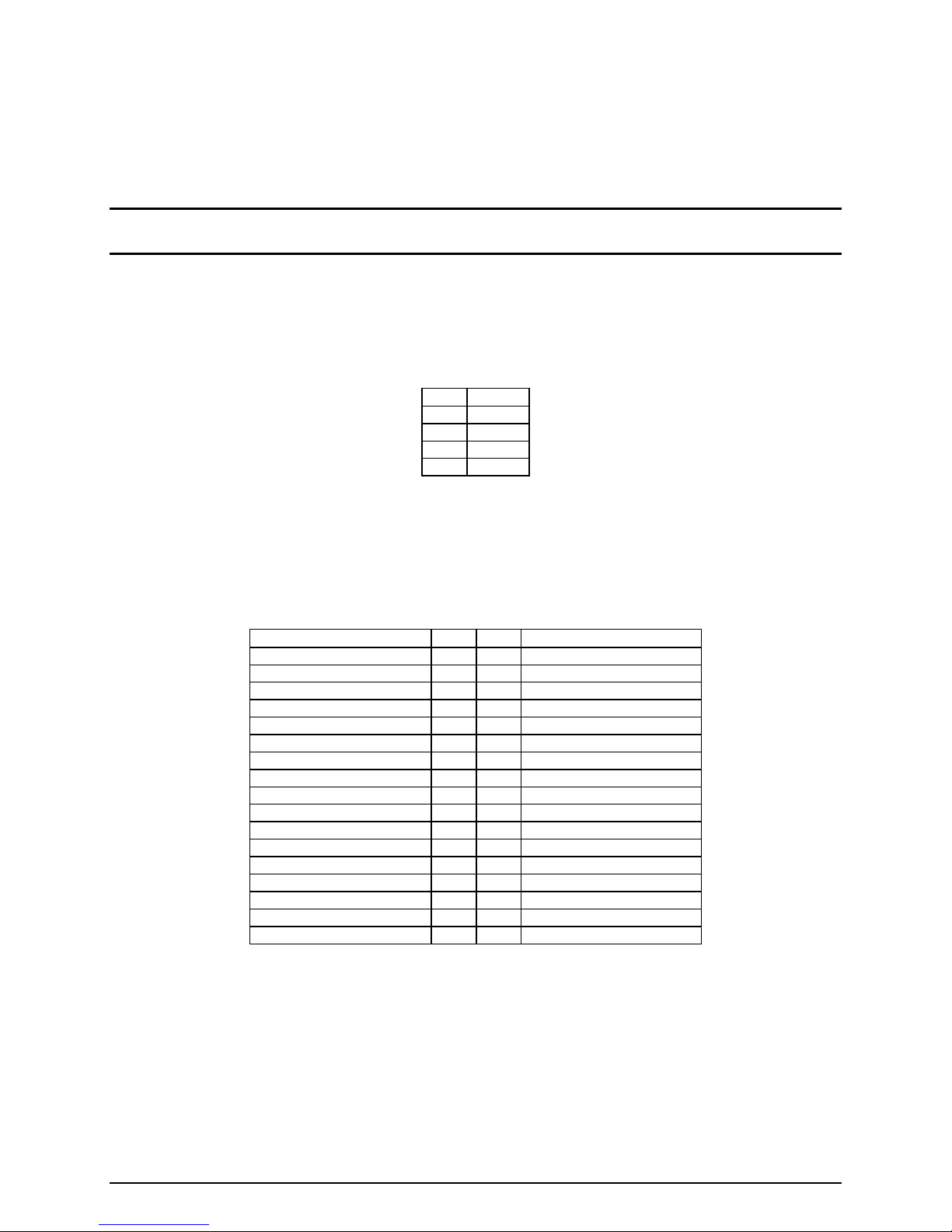
Revision History
Date Revision
Number
March 2006 1.0 Initial Release
Modifications
Revision 1.0 ii
Page 3

Disclaimers
Information in this document is provided in connection with Intel® products. No license, express
or implied, by estoppel or otherwise, to any intellectual property rights is granted by this
document. Except as provided in Intel's Terms and Conditions of Sale for such products, Intel
assumes no liability whatsoever, and Intel disclaims any express or implied warranty, relating to
sale and/or use of Intel products including liability or warranties relating to fitness for a particular
purpose, merchantability, or infringement of any patent, copyright or other intellectual property
right. Intel products are not intended for use in medical, life saving, or life sustaining
applications. Intel may make changes to specifications and product descriptions at any time,
without notice.
Designers must not rely on the absence or characteristics of any features or instructions marked
"reserved" or "undefined." Intel reserves these for future definition and shall have no
responsibility whatsoever for conflicts or incompatibilities arising from future changes to them.
This document contains information on products in the design phase of development. Do not
finalize a design with this information. Revised information will be published when the product
is available. Verify with your local sales office that you have the latest datasheet before
finalizing a design.
The Intel® Server Chassis SR1475 and Intel® Server System SR1475NH1-E may contain
design defects or errors known as errata which may cause the product to deviate from
published specifications. Current characterized errata are available on request.
This document and the software described in it is furnished under license and may only be used
or copied in accordance with the terms of the license. The information in this manual is
furnished for informational use only, is subject to change without notice, and should not be
construed as a commitment by Intel Corporation. Intel Corporation assumes no responsibility or
liability for any errors or inaccuracies that may appear in this document or any software that may
be provided in association with this document.
Except as permitted by such license, no part of this document may be reproduced, stored in a
retrieval system, or transmitted in any form or by any means without the express written consent
of Intel Corporation.
Intel, Pentium, Celeron and Xeon are trademarks or registered trademarks of Intel Corporation.
*Other brands and names may be claimed as the property of others.
Copyright © Intel Corporation 2006.
Revision 1.0 iii
Page 4

Table of Contents
1. Intel® Server Chassis SR1475 Feature Summary ........................................................- 13 -
1.1 Chassis Views ...................................................................................................- 13 -
1.2 Chassis Dimensions ..........................................................................................- 14 -
1.3 Intel® Server Chassis SR1475 System Components.........................................- 14 -
1.4 Rear Panel Components ...................................................................................- 15 -
1.5 Hard Drive and Peripheral Bays ........................................................................- 15 -
1.6 Control Panel .....................................................................................................- 16 -
1.7 Power Sub-system.............................................................................................- 18 -
1.8 System Cooling..................................................................................................- 18 -
1.9 Chassis Security ................................................................................................- 18 -
1.10 Rack and Cabinet Mounting Options .................................................................- 18 -
1.11 Front Bezels.......................................................................................................- 18 -
2. Cooling Sub-System ......................................................................................................- 20 -
2.1 System Fans......................................................................................................- 21 -
2.2 Power Supply Fans............................................................................................- 22 -
2.3 CPU/Memory Air Duct and Side Air Baffle.........................................................- 22 -
3. Peripheral and Hard Drive Support...............................................................................- 24 -
3.1 Slim-line Drive Bay ............................................................................................- 24 -
3.1.1 Floppy Drive Support With or Without Backplane Present ................................- 25 -
3.1.2 Optional Floppy Drive Configuration..................................................................- 26 -
3.1.3 CD-ROM or DVD-CDR Drive Use With or Without Backplane Present.............- 26 -
3.2 Hard Disk Drive Bays.........................................................................................- 28 -
3.2.1 Hot-Swap Hard Disk Drive Trays.......................................................................- 28 -
3.2.2 Fixed Drive Trays...............................................................................................- 29 -
3.2.3 Drive Blanks.......................................................................................................- 29 -
3.3 Hot-Swap SCSI Backplane................................................................................- 30 -
3.3.1 SCSI Backplane Board Layout ..........................................................................- 30 -
3.3.2 SCSI Backplane Functional Architecture...........................................................- 31 -
3.3.3 SCSI Backplane Connector Definitions .............................................................- 34 -
3.4 Hot-Swap SATA Backplane...............................................................................- 37 -
3.4.1 SATA Backplane Layout....................................................................................- 38 -
3.4.2 SATA Backplane Functional Architecture..........................................................- 39 -
3.4.3 SATA Backplane Connector Definitions ............................................................- 41 -
4. Standard Control Panel .................................................................................................- 44 -
Revision 1.0 iv
Page 5

4.1 Standard Control Panel Buttons .......................................................................- 44 -
4.2 Standard Control Panel LED Indicators.............................................................- 45 -
4.2.1 Power / Sleep LED ............................................................................................- 46 -
4.2.2 Drive Activity LED ..............................................................................................- 46 -
4.2.3 System Identification LED..................................................................................- 47 -
4.3 Control Panel Connectors..................................................................................- 47 -
4.4 Internal Control Panel Assembly Headers.........................................................- 47 -
5. PCI Riser Cards and Assembly.....................................................................................- 49 -
5.1 Riser Card Options ............................................................................................- 50 -
6. Power Sub-system .........................................................................................................- 51 -
6.1 Mechanical Specifications .................................................................................- 51 -
6.2 Airflow Requirements.........................................................................................- 52 -
6.3 Acoustics ...........................................................................................................- 52 -
6.4 Temperature ......................................................................................................- 53 -
6.5 Output Connectors.............................................................................................- 53 -
6.5.1 P1 Main power connector ..................................................................................- 54 -
6.5.2 P2 Processor Power Connector ........................................................................- 54 -
6.5.3 HD Power Connector (P3) .................................................................................- 55 -
6.5.4 Slim-line Power Connector (P4) ........................................................................- 55 -
6.6 AC Inlet Connector ............................................................................................- 55 -
6.7 Marking and Identification..................................................................................- 55 -
6.8 AC Input Voltage................................................................................................- 56 -
6.9 AC Line Transient Specification.........................................................................- 56 -
6.10 Susceptibility......................................................................................................- 57 -
6.10.1 Electrostatic Discharge Susceptibility ................................................................- 57 -
6.10.2 Fast Transient/Burst ..........................................................................................- 57 -
6.10.3 Radiated Immunity.............................................................................................- 57 -
6.10.4 Surge Immunity..................................................................................................- 57 -
6.11 AC Line Fast Transient (EFT) Specification ......................................................- 58 -
6.12 AC Line Dropout / Holdup..................................................................................- 58 -
6.12.1 AC Line 5VSB Holdup .......................................................................................- 58 -
6.13 Power Recovery ................................................................................................- 58 -
6.13.1 Voltage Brown Out.............................................................................................- 59 -
6.13.2 Voltage Interruptions..........................................................................................- 59 -
6.14 AC Line Inrush ...................................................................................................- 59 -
6.15 AC Line Isolation Requirements ........................................................................- 59 -
6.16 AC Line Leakage Current ..................................................................................- 59 -
Revision 1.0 v
Page 6

6.17 AC Line Fuse .....................................................................................................- 60 -
6.18 Power Factor Correction....................................................................................- 60 -
6.19 Efficiency ...........................................................................................................- 60 -
6.20 Grounding ..........................................................................................................- 60 -
6.21 Remote Sense ...................................................................................................- 60 -
6.22 Output Power / Currents ....................................................................................- 61 -
6.22.1 Standby Outputs ................................................................................................- 61 -
6.22.2 Fan Operation in Stand-By Mode ......................................................................- 61 -
6.23 Voltage Regulation ............................................................................................- 61 -
6.23.1 Dynamic Loading ...............................................................................................- 62 -
6.24 Capacitive Loading ............................................................................................- 62 -
6.25 Closed loop stability...........................................................................................- 62 -
6.26 Common Mode Noise ........................................................................................- 63 -
6.27 Ripple / Noise ....................................................................................................- 63 -
6.28 Soft Starting .......................................................................................................- 63 -
6.29 Zero Load Stability Requirements .....................................................................- 63 -
6.30 Timing Requirements.........................................................................................- 63 -
6.31 Residual Voltage Immunity in Standby mode ....................................................- 66 -
6.32 Protection Circuits..............................................................................................- 66 -
6.33 Over-Current Limit (OCP) ................................................................................- 67 -
6.34 Over-Voltage Protection (OVP) ........................................................................- 67 -
6.35 Over-Temperature Protection (OTP) ................................................................- 68 -
6.36 Control and Indicator Functions.........................................................................- 68 -
6.37 PSON
#
Input Signal ..........................................................................................- 68 -
6.38 PWOK (Power OK) Output Signal .....................................................................- 69 -
6.39 Environmental Requirements ............................................................................- 70 -
6.39.1 Temperature ......................................................................................................- 70 -
6.39.2 Humidity.............................................................................................................- 70 -
6.39.3 Altitude...............................................................................................................- 70 -
6.39.4 Mechanical Shock..............................................................................................- 70 -
6.39.5 Random Vibration ..............................................................................................- 70 -
6.39.6 Thermal Shock (Shipping) .................................................................................- 70 -
6.39.7 Ecological Requirements ...................................................................................- 70 -
6.39.8 Catastrophic Failure...........................................................................................- 70 -
7. Electromagnetic Compatibility......................................................................................- 71 -
7.1 EMI ....................................................................................................................- 71 -
7.2 Input Line Current Harmonic Content (PFC) ....................................................- 71 -
Revision 1.0 vi
Page 7

7.3 Magnetic Leakage Fields...................................................................................- 72 -
7.4 Voltage Fluctuations and Flicker........................................................................- 72 -
7.5 Reliability / Warranty / Service...........................................................................- 72 -
7.5.1 Component De-rating ........................................................................................- 72 -
7.5.2 Component Life requirement .............................................................................- 72 -
7.6 Mean Time Between Failures (MTBF)...............................................................- 72 -
7.6.1 Warranty Period.................................................................................................- 72 -
7.6.2 Serviceability......................................................................................................- 73 -
7.7 Power Supply Returned for Repair ....................................................................- 73 -
7.8 Modifications / Change Control..........................................................................- 73 -
7.9 Power Supply Compliance Overview.................................................................- 73 -
7.10 Power Supplies Compliance Information...........................................................- 74 -
7.11 EMC Compliance Information............................................................................- 74 -
7.12 Immunity Compliance Information .....................................................................- 75 -
7.13 Harmonics & Voltage Flicker Compliance Information ......................................- 75 -
7.14 Environmental / Ecology Compliance Information .............................................- 75 -
7.15 Other Safety Requirement Notations.................................................................- 76 -
7.15.1 Certification Conditions......................................................................................- 76 -
7.15.2 Isolation Between Primary - Secondary.............................................................- 76 -
7.15.3 Creepage & Clearance Requirements...............................................................- 76 -
7.15.4 Leakage Current Maximums..............................................................................- 76 -
7.15.5 Max Surface Temperatures ...............................................................................- 76 -
7.15.6 Date Coded Serial Numbers..............................................................................- 76 -
7.15.7 Power Input Electrical Ratings...........................................................................- 76 -
7.15.8 Maximum Allowable Temperatures on Inlet Receptacles..................................- 76 -
7.15.9 Maximum Allowable Temperatures on Power Cords.........................................- 76 -
8. Supported Intel® Server Boards....................................................................................- 77 -
8.1 Intel® Server Board SE7230NH1-E Feature Set................................................- 77 -
9. Regulatory, Environmentals, and Specifications........................................................- 80 -
9.1 Product Regulatory Compliance ........................................................................- 80 -
9.1.1 Product Safety Compliance ...............................................................................- 80 -
9.1.2 Product EMC Compliance .................................................................................- 80 -
9.1.3 Product Regulatory Compliance Markings ........................................................- 81 -
9.2 Electromagnetic Compatibility Notices ..............................................................- 81 -
9.2.1 USA ...................................................................................................................- 81 -
9.2.2 FCC Verification Statement ...............................................................................- 82 -
9.2.3 ICES-003 (Canada) ...........................................................................................- 82 -
Revision 1.0 vii
Page 8

9.2.4 Europe (CE Declaration of Conformity) .............................................................- 82 -
9.2.5 Japan EMC Compatibility ..................................................................................- 83 -
9.2.6 BSMI (Taiwan) ...................................................................................................- 83 -
9.3 Replacing the Back up Battery ..........................................................................- 84 -
9.4 System Level Environmental Limits...................................................................- 85 -
9.5 Serviceability......................................................................................................- 85 -
Appendix A: Intel
®
Server Chassis SR1475 Integration and Usage Tips...........................- 3 -
Glossary...................................................................................................................................- 4 -
Revision 1.0 viii
Page 9

List of Figures
Figure 1. Front Chassis View with Bezel ................................................................................- 13 -
Figure 2. Front Chassis View without Bezel ...........................................................................- 13 -
Figure 3. Rear Chassis View ..................................................................................................- 13 -
Figure 4. Major Chassis Components.....................................................................................- 14 -
Figure 5. Back Panel Feature Overview .................................................................................- 15 -
Figure 6. Front Panel Feature Overview.................................................................................- 16 -
Figure 7. Control Panel Module ..............................................................................................- 17 -
Figure 8. Standard Control Panel Overview ...........................................................................- 17 -
Figure 9. Optional Front Bezel ................................................................................................- 19 -
Figure 10. Front Bezel Options ...............................................................................................- 19 -
Figure 11. Intel
Figure 12. Intel
Figure 13. Intel
Figure 14. Air Baffle ................................................................................................................- 22 -
®
Server Chassis SR1475 Cooling Subsystem ...............................................- 20 -
®
Server Chassis SR1475 System Fans 4, 5, 6, 7, 8 ......................................- 21 -
®
Server System SE7230NH1-E System Fan Headers 4, 5, 6, 7, 8 ...............- 21 -
Figure 15. CPU/Memory Air Duct ...........................................................................................- 23 -
Figure 16. Intel
®
Server Chassis SR1475 Peripheral Bay Configuration Options...................- 24 -
Figure 17. View of Slim-line Drive Bay....................................................................................- 24 -
Figure 18. Optional Floppy Drive Configuration......................................................................- 26 -
Figure 19. Hard Disk Drive Bay ..............................................................................................- 28 -
Figure 20. Hard Drive Tray Assembly.....................................................................................- 29 -
Figure 21. Drive Tray with Drive Blank ...................................................................................- 29 -
Figure 22. SCSI Backplane Layout.........................................................................................- 30 -
Figure 23. SCSI Backplane Functional Diagram ....................................................................- 31 -
Figure 24. Intel
®
Server Chassis SR1475 SCSI HSBP I2C Bus Connection Diagram ...........- 33 -
Figure 25. 68-Pin SCSI Cable Connector ...............................................................................- 34 -
Figure 26. 80-pin SCA2 SCSI Interface ..................................................................................- 36 -
Figure 27. SATA Backplane Layout........................................................................................- 38 -
Figure 28. SATA Backplane Layout........................................................................................- 38 -
Figure 29. SATA Backplane Functional Block Diagram..........................................................- 39 -
Figure 30. Intel
®
Server Chassis SR1475 SATA HSBP I2C Bus Connection Diagram ..........- 40 -
Figure 31. Standard Control Panel Assembly Module ............................................................- 44 -
Figure 32. Standard Control Panel Buttons ............................................................................- 44 -
Figure 34. PCI Riser Bracket and Optional PCI-X* and PCI Express* Risers ........................- 49 -
Figure 35. 1U Full Height PCI-X* Riser Card Mechanical Drawing.........................................- 50 -
Revision 1.0 ix
Page 10

Figure 36. 1U Full Height PCI Express* Riser Card Mechanical Drawing ..............................- 50 -
Figure 37. Power Supply Enclosure Drawing .........................................................................- 51 -
Figure 38. Airflow Characteristics ...........................................................................................- 52 -
Figure 39. Output Voltage Timing ...........................................................................................- 64 -
Figure 40. Turn On/Off Timing (Power Supply Signals)..........................................................- 66 -
Figure 41. PSON# Required Signal Characteristic. ................................................................- 69 -
Figure 42. SE7230NH1-E (LX) Board Layout .........................................................................- 78 -
Revision 1.0 x
Page 11

List of Tables
Table 1. Chassis Dimensions .................................................................................................- 14 -
Table 2. Major Chassis Components......................................................................................- 15 -
Table 3. Individual Fan Assembly Pin-out (J5J1, J4J1, J4J3, J4J2).......................................- 22 -
Table 4. 4-pin Floppy Power Connector Pin-out (J3)..............................................................- 25 -
Table 5. 34-pin Floppy Connector Pin-out (J2) .......................................................................- 25 -
Table 6. 50-pin CD-ROM Connector Pin-out (J6) ...................................................................- 26 -
Table 7. 4-pin CD-ROM Power Connector Pin-out (J5)..........................................................- 27 -
Table 8. 40-pin CD-ROM Connector Pin-out (J1) ...................................................................- 27 -
Table 9. SCSI Backplane Power Connector Pin-out (J1) .......................................................- 34 -
Table 10. UltraWide (SE) and Ultra2 (LVD) Ultra320 SCSI Connector Pin-out (J8)...............- 35 -
Table 11. 80-pin SCA2 SCSI Interface Pin-out.......................................................................- 36 -
Table 12. LED Function ..........................................................................................................- 41 -
Table 13. SATA Backplane Power Connector Pin-out............................................................- 41 -
Table 14. 7-Pin SATA Connector Pin-out (J2, J3, J4, J5, J6).................................................- 42 -
Table 15. 22-Pin SATA Connector Pin-out .............................................................................- 42 -
Table 16. Standard Control Panel Button Functions...............................................................- 45 -
Table 17. Standard Control Panel LED Functions ..................................................................- 46 -
Table 18. SSI Power LED Operation ......................................................................................- 46 -
Table 19. External USB Connector (J2)..................................................................................- 47 -
Table 20. 50-pin Control Panel Connector (J3) ......................................................................- 48 -
Table 21. Internal USB Header (J9F2) ...................................................................................- 48 -
Table 22. Acoustic Requirements ...........................................................................................- 53 -
Table 23. Environmental Requirements.................................................................................- 53 -
Table 24. Cable Lengths.........................................................................................................- 53 -
Table 25. P1 Main Power Connector .....................................................................................- 54 -
Table 26. P2 Processor Power Connector.............................................................................- 54 -
Table 27. HD Power Connector .............................................................................................- 55 -
Table 28. Slim-line Power Connector ....................................................................................- 55 -
Table 29. AC Input Rating.......................................................................................................- 56 -
Table 30. AC Line Sag Transient Performance ....................................................................- 56 -
Table 31. AC Line Surge Transient Performance .................................................................- 57 -
Table 32. Performance Criteria...............................................................................................- 57 -
Table 33. Dropout Criteria.......................................................................................................- 58 -
Table 34. Load Ratings..........................................................................................................- 61 -
Revision 1.0 xi
Page 12

Table 35. Voltage Regulation Limits .......................................................................................- 61 -
Table 36. Transient Load Requirements.................................................................................- 62 -
Table 37. Capacitve Loading Conditions ................................................................................- 62 -
Table 38. Ripple and Noise.....................................................................................................- 63 -
Table 39. Output Voltage Timing ............................................................................................- 64 -
Table 40. Turn On/Off Timing .................................................................................................- 65 -
Table 41. Over Current Protection (OCP)...............................................................................- 67 -
Table 42. Over-Voltage Protection (OVP) Limits ....................................................................- 67 -
Table 43. PSON
#
Signal Characteristic...................................................................................- 68 -
Table 44. PWOK Signal Characteristics .................................................................................- 69 -
Table 45. Harmonic Limits, Class A equipment ......................................................................- 71 -
Table 46: Baseboard Layout Reference .................................................................................- 79 -
Table 47. System Office Environment Summary ....................................................................- 85 -
Table 48. Mean Time To Repair Estimate ..............................................................................- 86 -
Revision 1.0 xii
Page 13
Intel® Server Chassis SR1475/ Intel® Server System SR1475NH1-E
1. Intel® Server Chassis SR1475 Feature Summary
The Intel® Server Chassis SR1475 is a 1U server chassis specifically designed to support the
®
Intel
Server Board SE7230NH1-E. The Intel® Server Chassis SR1475 is available as a
standalone chassis solution from Intel, and as an integrated system. The Intel
SR1475NH1-E consists of the Intel
®
Server Board SE7230NH1-E integrated into the Intel®
Server Chassis SR1475. The server board and the server chassis have feature sets designed to
support the high-density server market.
®
Server System
The Intel
SE7230NH1LC version and the SE7230NH1LX version. Only the SE7230NH1LX version is
available for integration into the Intel
®
Server Board SE7230NH1-E is available in two different configurations, the
®
Server Chassis SR1475, and all references to the Intel®
Server Board SE7230NH1-E in this document refers to the SE7230NH1LX version of the server
board. This document provides details on the server chassis feature set and technical
specifications. For technical details related to the Intel
refer to the Intel
®
Server Board SE7230NH1-E Technical Product Specification.
®
Server Board SE7230NH1-E, please
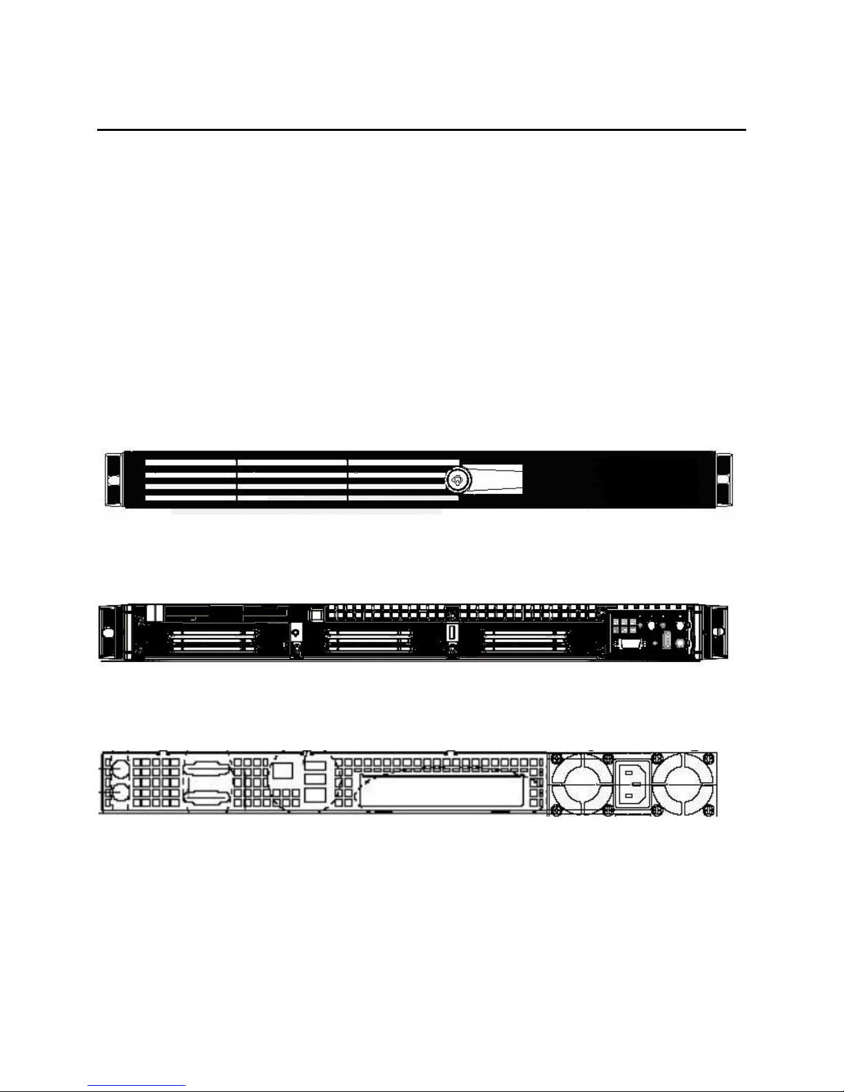
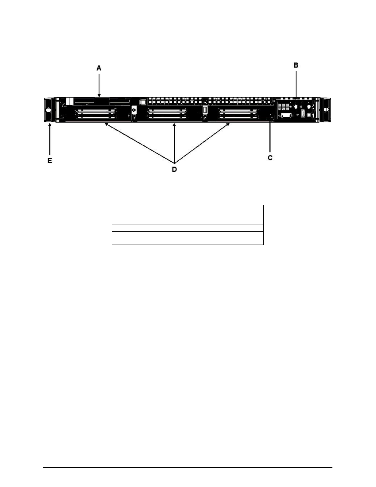
1.1 Chassis Views
Figure 1. Front Chassis View with Bezel
Figure 2. Front Chassis View without Bezel
Figure 3. Rear Chassis View
- 13 -
Page 14
Intel® Server Chassis SR1475 / Intel® Server System SR1475NH1-E
1.2 Chassis Dimensions
Table 1. Chassis Dimensions
Height 43.25 mm 1.703”
Width 430 mm 16.930”
Depth 672 mm 26.457”
Max. Weight 14.1 kg 31 LBS
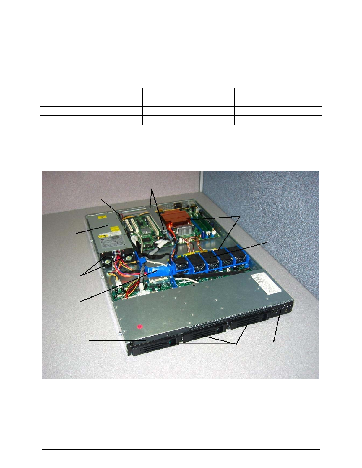
1.3 Intel® Server Chassis SR1475 System Components
C
A
J
I
H
B
G
D
E
F
Revision 1.0 - 14 -
Figure 4. Major Chassis Components
Page 15
Intel® Server Chassis SR1475 / Intel® Server System SR1475NH1-E
Table 2. Major Chassis Components
A Power Supply F Control Panel
B Chassis Intrusion Switch G Hard Drive Bays
C PCI Riser Card Assembly Placement H Slim-line Drive Bay
D CPU Air Duct Placement I PS / Electronics Bay Isolation Air Baffle
E System Fan Module J Power Supply Fans
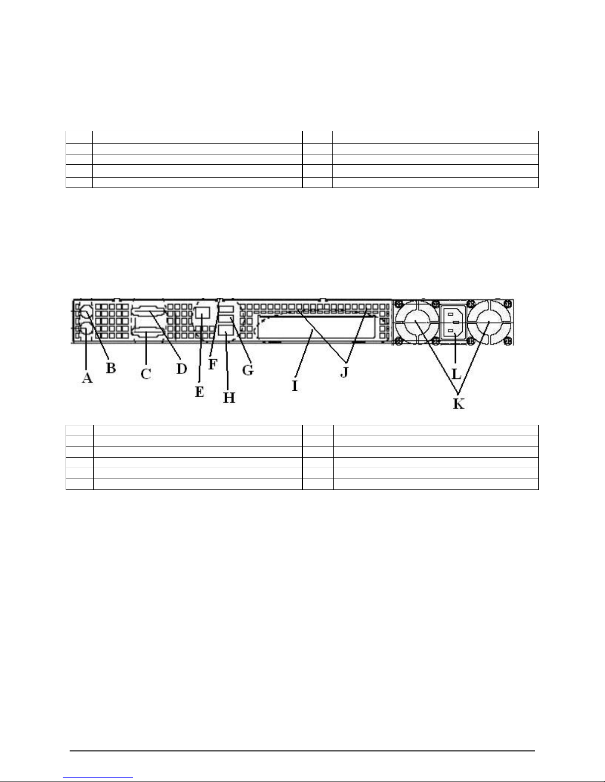
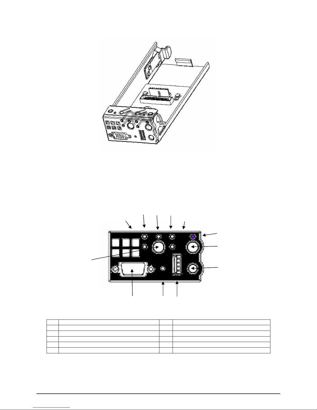
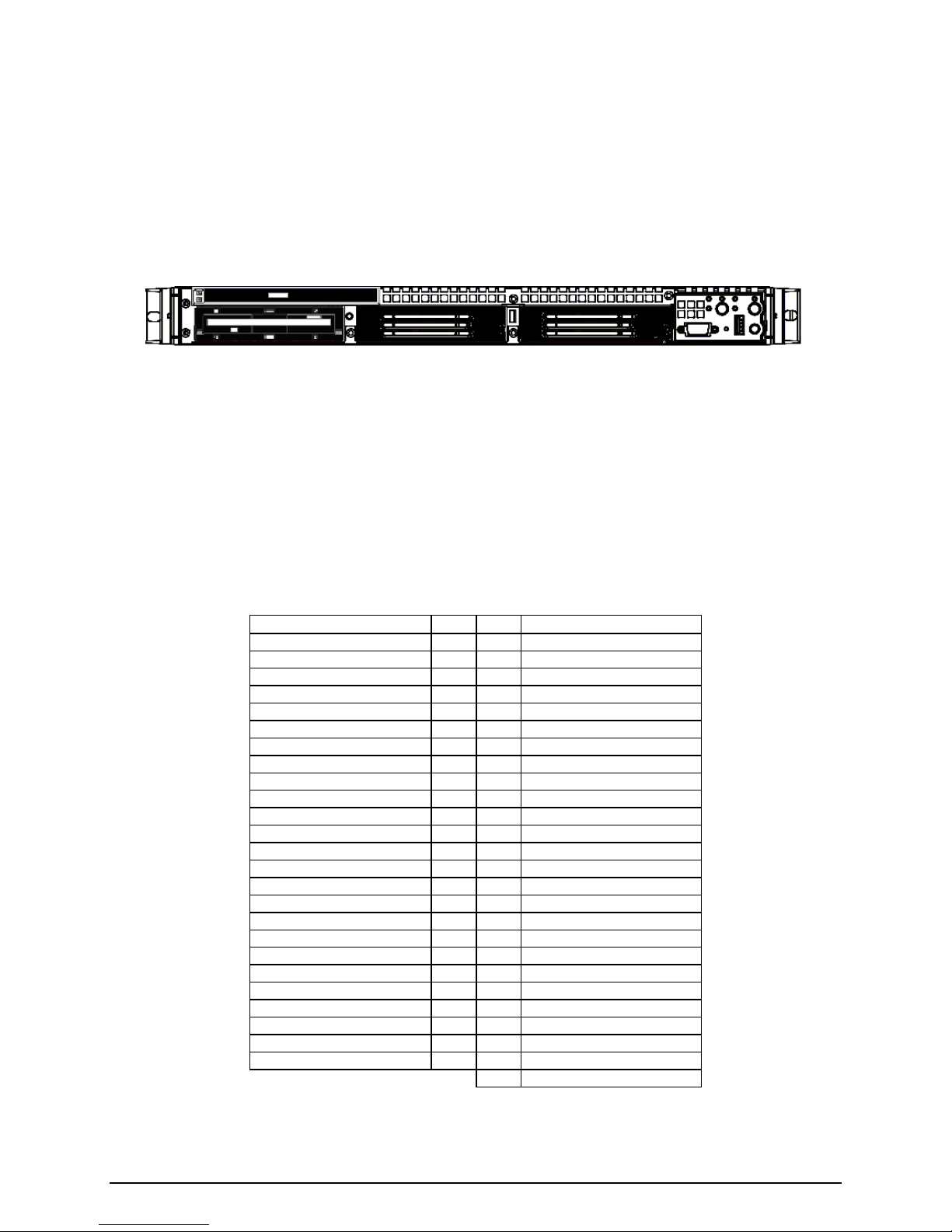
1.4 Rear Panel Components
On the back of the chassis are cutouts for all external I/O connectors found on the server board.
The I/O connector locations are pre-cut, so the use of an I/O shield is not required.
A PS2 keyboard connector G USB 2 connector
B PS2 mouse connector H NIC 1 connector (RJ45)
C Serial port A connector (DB9) I PCI card bracket (full-height)
D Video connector J Rear chassis venting holes
E NIC 2 connector (RJ45) K Power Supply fans
F USB 1 connector L AC Power Receptacle
Figure 5. Back Panel Feature Overview
1.5 Hard Drive and Peripheral Bays
The server chassis is designed to support several different hard drive and peripheral
configurations. The hard drive bay is designed to support up to three fixed SATA or SCSI
drives, or three hot-swappable SATA or SCSI drives. SATA and SCSI hot-swap configurations
require an orderable accessory kit which includes the necessary cables, drive trays and
backplane. Reference the Intel
detailed accessory information.
The slim-line peripheral bay is capable of supporting any of the following slim-line devices: CDROM drive, DVD Drive, DVD/CDR Drive, or floppy drive. If both a CD-ROM or DVD/CDR and
floppy drive are required, an optional kit is available to convert the first 1” hard drive bay to a
floppy drive bay. The kit includes the necessary cables and slim-line floppy drive mounting tray.
®
Server Chassis SR1400 Spares/Parts and Configuration List for
Revision 1.0 - 15 -
Page 16
Intel® Server Chassis SR1475 / Intel® Server System SR1475NH1-E
Figure 6. Front Panel Feature Overview
A Slim-line drive bay (CD-ROM or DVD/CDR or
Floppy)
B Control Panel
C Hard Drive Fault/Activity LED
D 1” Hard Drive Bays
E Chassis Handle
1.6 Control Panel
The server chassis control panel assembly is pre-assembled and modular in design. The entire
module assembly slides into a predefined slot in the front of the chassis.
Revision 1.0 - 16 -
Page 17
Intel® Server Chassis SR1475 / Intel® Server System SR1475NH1-E
Figure 7. Control Panel Module
The control panel supports several push buttons and status LEDs, and includes USB and video
ports to centralize system control, monitoring, and accessibility to within a common compact
design. The following diagram overviews the layout and functions of the control panel.
C D E
B
F
G
H
A
I
L
Figure 8. Standard Control Panel Overview
K
J
A Power / Sleep Button G System Identification LED
B NIC #2 Activity LED H System Identification Button
C NIC #1 Activity LED I System Reset Button
D Power / Sleep LED J USB 2.0 Connector
E Not Used K Recessed NMI Button (Tool Required)
F Hard Drive Activity LED L Video connector (not supported on SR1475)
Revision 1.0 - 17 -
Page 18

Intel® Server Chassis SR1475 / Intel® Server System SR1475NH1-E
1.7 Power Sub-system
The power sub-system of the server chassis consists of a single non-redundant 350 W power
supply (PS) and provides several integrated management features including:
• Status LED
• Over-temperature protection circuitry
• Over-voltage protection circuitry
The power supply operates within the following voltage ranges and ratings: 100-127VAC (V) ∼
at 50/60 Hertz (Hz), 6 Ampere (A) maximum (max); 200-240VAC∼ at 50/60 Hz, 3 A maximum.
1.8 System Cooling
The server chassis provides non-redundant system fans and dual non-redundant power supply
fans to provide sufficient air flow for fixed and hot-swap drive configurations, processors,
memory, and an add-in card, when external ambient temperatures remain within specified limits.
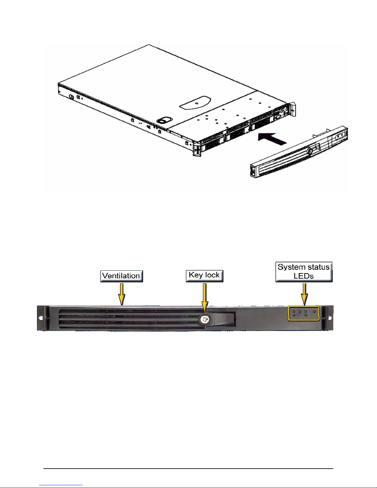
1.9 Chassis Security
The server chassis provides support for several system security features including a lockable
front bezel, chassis intrusion switch, and a Kensington* style lock attach point.
1.10 Rack and Cabinet Mounting Options
The server chassis was designed to support 19” wide by up to 24”-30” deep server cabinets.
The chassis can be configured to support either a relay rack / cabinet mount kit that can be
configured to support both 2-post racks and 4-post cabinets; or a tool-less sliding rail kit that is
used to mount the chassis into a standard (19” by up to 30” deep) EIA-310D compatible server
cabinet.
1.11 Front Bezels
The optional front bezel is made of molded plastic and uses a snap-on design. When installed,
its design allows for maximum airflow.
Revision 1.0 - 18 -
Page 19
Intel® Server Chassis SR1475 / Intel® Server System SR1475NH1-E
Figure 9. Optional Front Bezel
Light pipes in the front bezel supporting the standard control panel allow the system status
LEDs to be monitored with the bezel installed
Figure 10. Front Bezel Options
Revision 1.0 - 19 -
Page 20
Intel® Server Chassis SR1475/ Intel® Server System SR1475NH1-E
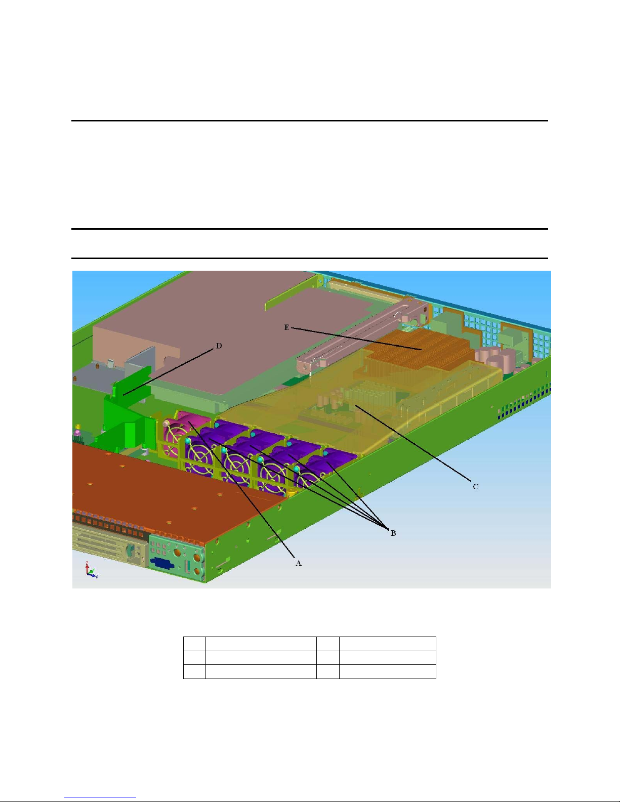
2. Cooling Sub-System
The cooling sub-system on the server chassis is compromised of four 40x40x56mm dual rotor
fans, one 40x40x28mm single rotor fan, two 40x40x28mm power supply fans, a CPU/memory
air duct, and a PS/electronics bay isolation air baffle, to provide the necessary cooling and
airflow to the system. A fan on the processor heat sink is not necessary in this chassis. In
order to maintain the necessary airflow within the system, the air baffle, CPU/memory air duct,
and the top cover need to be properly installed.
Note: The Intel
®
Server Chassis SR1475 does not support redundant cooling. Should a fan fail,
the system should be brought down as soon as possible to replace the failed fan.
Figure 11. Intel® Server Chassis SR1475 Cooling Subsystem
A System Fan #4 D Air Baffle
B Fans 5, 6, 7, 8 E Processor Heat Sink
C CPU / Memory Air Duct
- 20 -
Page 21
Intel® Server Chassis SR1475 / Intel® Server System SR1475NH1-E
2.1 System Fans
The server chassis system fans consist of four 40x40x56mm dual rotor and one 40x40x28mm
single rotor multi-speed fans, which provide the primary airflow for the system. The four dual
rotor fans provide the primary cooling for the processor, GMCH, and memory components on
the Intel
PCI add-in card, the ICH7R, and the PXH chipset components.
Removal and insertion of individual fans is a tool-less operation, and provides for ease of
installation and serviceability of the server chassis cooling subsystem. The individual fans are
not hot-swappable. The server must be turned off and power removed from the system before
any of the fans can safely be replaced.
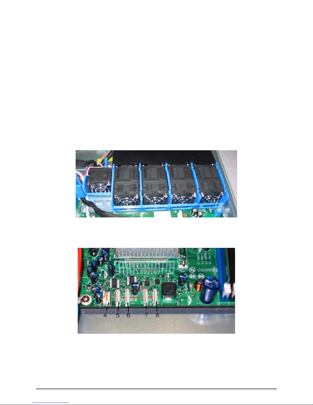
Each dual rotor fan has an 8-pin wire harness which connects to the system fan headers 5, 6, 7
and 8 on the server board. These are shown, from left to right, in the following figure. Each fan
harness provides power and tachometer lines allowing the fans to be monitored independently
by server management software.
®
Server Board SE7230NH1-E. The single rotor fan provides the primary cooling for a
Figure 12. Intel® Server Chassis SR1475 System Fans 4, 5, 6, 7, 8
Figure 13. Intel
®
Server System SE7230NH1-E System Fan Headers 4, 5, 6, 7, 8
Revision 1.0 - 21 -
Page 22
Intel® Server Chassis SR1475 / Intel® Server System SR1475NH1-E
The following table provides the pin-outs for each dual rotor fan header.
Table 3. Individual Fan Assembly Pin-out (J5J1, J4J1, J4J3, J4J2)
Pin Signal Name Description
1 FAN_SPEED_CNTL2 Control the fan speed
2 FAN_FAIL FAN_TACH signal
3 GND Power Supply Ground
4 Reserved Reserved
5 GND Power Supply Ground
6 GND Power Supply Ground
7 FAN_FAIL FAN_TACH signal
8 Fan speed control Variable Speed Fan Power
The single rotor fan has a standard 3 or 4-pin SSI fan header that connects directly to the server
board system fan header #4 (J5J2).
Each fan within the module is capable of supporting multiple speeds. If the internal ambient
temperature of the system exceeds the value programmed into the fan control via BIOS, the
system will automatically increase the rotational speed for all the fans within fan module.
Note: There is no fan redundancy. Should a fan fail, the system should be shut down as soon
as possible to have the fan replaced. The system fans are not hot-swapable.
2.2 Power Supply Fans
The power supply supports two non-redundant 40mm fans. They are responsible for the cooling
of the power supply and drive bay 1 (the far left hard drive as viewed from the front of the
chassis).
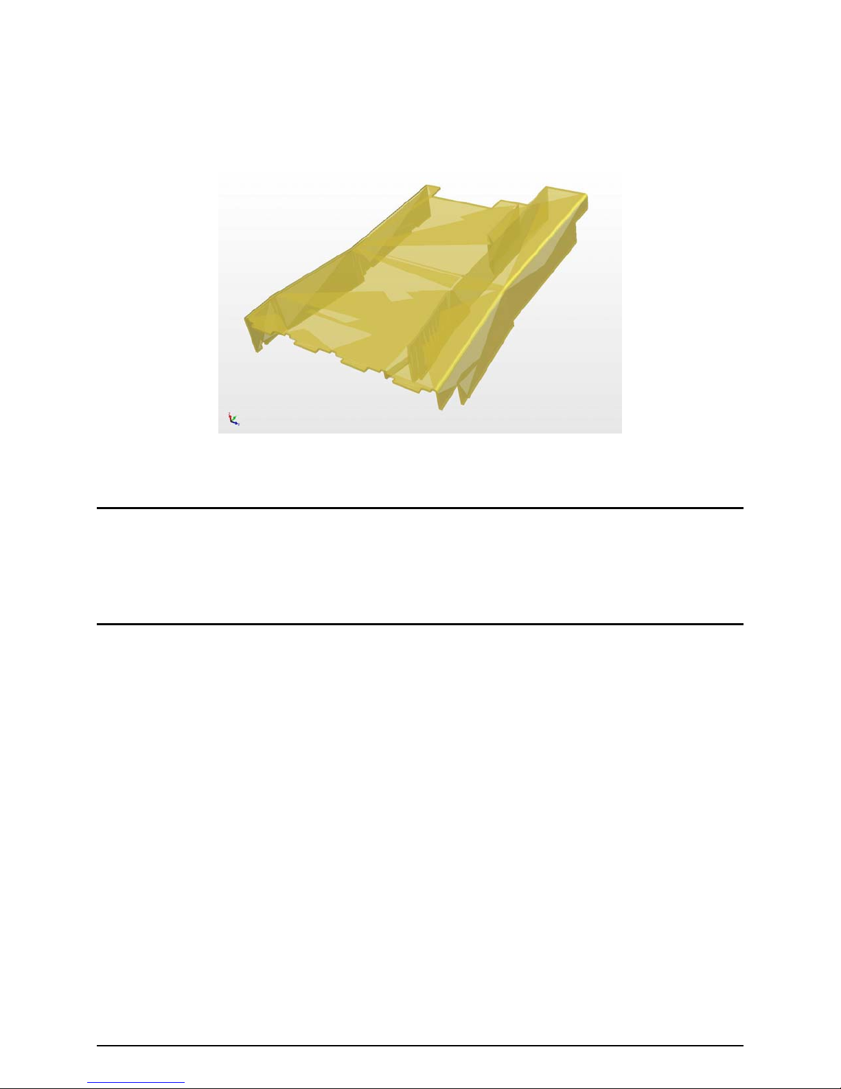
2.3 CPU/Memory Air Duct and Side Air Baffle
The chassis requires the use of a CPU/memory air duct and power supply / electronics bay
isolation air baffle to direct airflow and sustain appropriate air pressure.
An air baffle is used to isolate the airflow of the two power supply fans from that of the system
fan module. The baffle is mounted into three stand-offs with one end fitting under the back
edge of the hard drive bay
Revision 1.0 - 22 -
Figure 14. Air Baffle
Page 23
Intel® Server Chassis SR1475 / Intel® Server System SR1475NH1-E
The CPU/memory air duct must be properly installed to direct airflow through the processor
heatsink and the memory area of the system.
Figure 15. CPU/Memory Air Duct
Notes:
1. If the CPU/memory air duct is removed, the system will not meet the thermal cooling
requirements of the processor, which will most likely result in degraded performance as a result
of throttling or thermal shutdown of the system.
2. Once the air dam is removed from the CPU air duct, it cannot be reinstalled.
Revision 1.0 - 23 -
Page 24
Intel® Server Chassis SR1475/ Intel® Server System SR1475NH1-E
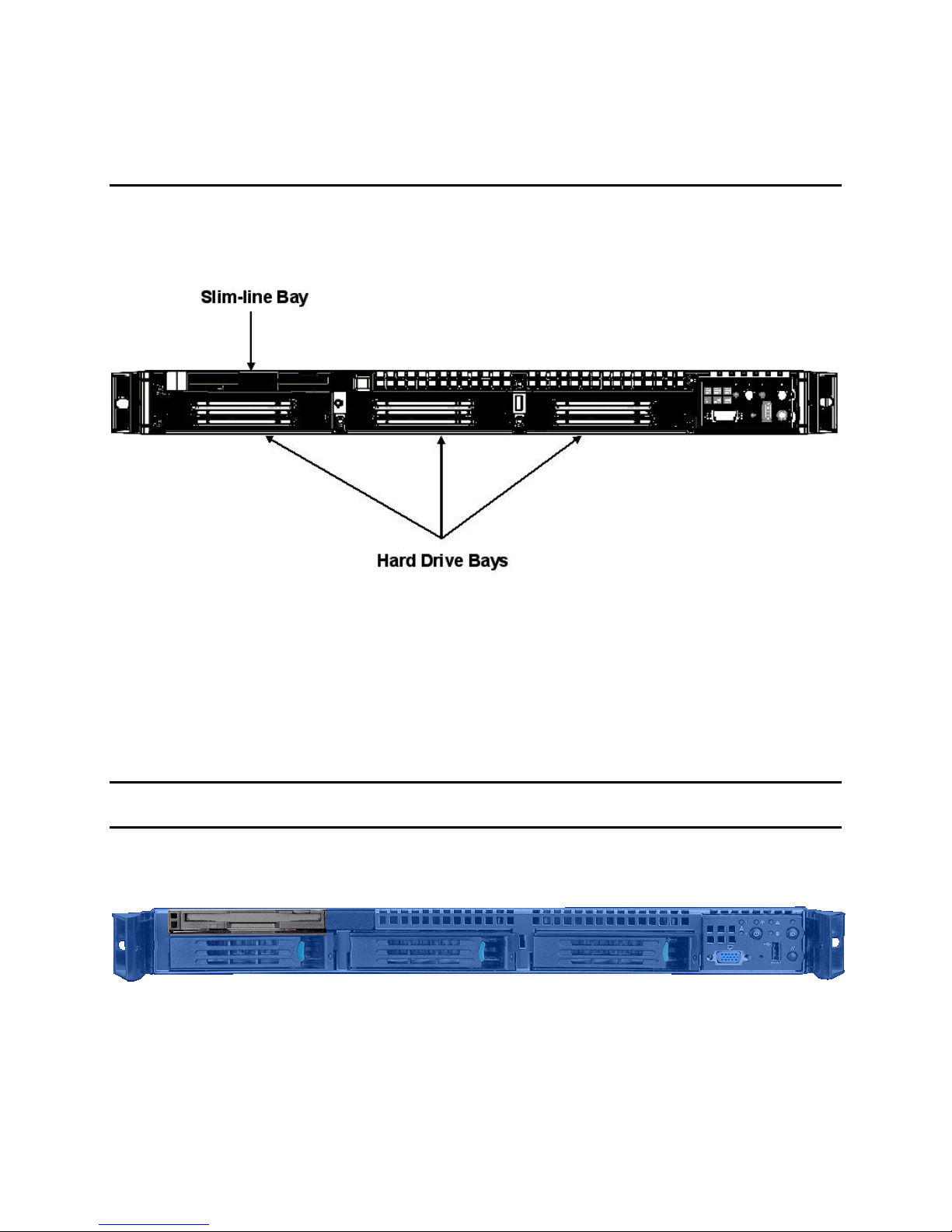
3. Peripheral and Hard Drive Support
The server chassis provides three hard drive bays and one slim-line peripheral drive bay at the
front of the chassis. The drive bays are designed to support both fixed and hot-swap SCSI and
SATA drive configurations.
Figure 16. Intel® Server Chassis SR1475 Peripheral Bay Configuration Options
3.1 Slim-line Drive Bay
The chassis provides a slim-line drive bay that can be configured for either CD-ROM,
DVD/CDRW, or floppy drives, with or without the presence of a backplane. Regardless of
whether a SATA or SCSI backplane is present, all slim-line devices attach directly to the Intel
Server Board SE7230NH1-E.
Note: The 100-pin connector on the SATA and SCSI backplane is not used in the Intel
®
Chassis SR1475 and the Intel® Server Board SE7230NH1-E.
Drives are mounted on a tool-less tray which allows for easy installation into and removal from
the chassis. The slim-line devices are not hot-swappable.
Figure 17. View of Slim-line Drive Bay
®
Server
- 24 -
Page 25
Intel® Server Chassis SR1475 / Intel® Server System SR1475NH1-E
3.1.1 Floppy Drive Support With or Without Backplane Present
The floppy drive is mated with an interposer card which provides the power and IO
interconnects between the drive, power supply, and the server board.
Note: The 100-pin connector on the backplane is not used with the Intel
®
Server Board
SE7230NH1-E.
The interposer card has three connectors. The first connector has 28 pins and is cabled directly
to the drive. The second connector has 4 pins and is cabled to the 2x3 pin power lead from the
power supply; this connector has the following pin-out.
Table 4. 4-pin Floppy Power Connector Pin-out (J3)
Pin Name
1 P12V
2 GND
3 GND
4 P5V
The power cable for the floppy drive is provided via a slim-line Y cable which comes with the
®
Intel
Server Chassis SR1475. The third connector has 34 pins and is cabled to the legacy
floppy connector on the server board; this connector has the following pin-out.
Table 5. 34-pin Floppy Connector Pin-out (J2)
Name Pin Pin Name
GND 1 2 FD_DENSEL0
GND 3 4 2M_MEDIA
GND 5 6 FD_DRATE0_L
GND 7 8 FD_INDEX_L
GND 9 10 FD_MTR0_L
GND 11 12 FD_DS1_L
GND 13 14 FD_DS0_L
GND 15 16 FD_MTR1_L
Unused 17 18 FD_DIR_L
GND 19 20 FD_STEP_L
GND 21 22 FD_WDATA_L
GND 23 24 FD_WGATE_L
GND 25 26 FD_TRK0_L
Unused 27 28 FD_WP_L
GND_FDD 29 30 FD_RDATA_L
GND 31 32 FD_HDSEL_L
MSEN0 33 34 FD_DSKCHG_L
Revision 1.0 - 25 -
Page 26
Intel® Server Chassis SR1475 / Intel® Server System SR1475NH1-E
3.1.2 Optional Floppy Drive Configuration
For system configurations that require a CD-ROM or DVD-CDR and floppy drive, where using a
USB floppy or USB CD-ROM is not desired, an accessory kit which consists of a slim-line floppy
drive tray and face plate can be used to install a floppy drive into the hard drive bay directly
beneath the slim-line drive bay a shown in the following diagram.
Figure 18. Optional Floppy Drive Configuration
3.1.3 CD-ROM or DVD-CDR Drive Use With or Without Backplane Present
The slim-line CD-ROM or DVD-CDR drive is mated with an interposer card which provides the
power and IO interconnects between the drive, power supply and the server board. The
interposer card has three connectors. The first connector has 50 pins and is plugged directly
into the drive connector; the connector has the following pin-out.
Table 6. 50-pin CD-ROM Connector Pin-out (J6)
Name Pin Pin Name
RSV_LCM 1 2 RSV_RCM
RSV_GND 3 4 GND
RST_IDE_S_L 5 6 IDE_SDD<8>
IDE_SDD<7> 7 8 IDE_SDD<9>
IDE_SDD<6> 9 10 IDE_SDD<10>
IDE_SDD<5> 11 12 IDE_SDD<11>
IDE_SDD<4> 13 14 IDE_SDD<12>
IDE_SDD<3> 15 16 IDE_SDD<13>
IDE_SDD<2> 17 18 IDE_SDD<14>
IDE_SDD<1> 19 20 IDE_SDD<15>
IDE_SDD<0> 21 22 IDE_SDDREQ
GND 23 24 IDE_SDIOR_L
IDE_SDIOW_L 25 26 GND
IDE_SIORDY 27 28 IDE_SDDACK_L
IRQ_IDE_S 29 30 NC_IDEIO16_L
IDE_SDA<1> 31 32 NC_CBL_DET_S
IDE_SDA<0> 33 34 IDE_SDA<2>
IDE_SDCS0_L 35 36 IDE_SDCS1_L
IDE_SEC_HD_ACT_L 37 38 P5V
P5V 39 40 P5V
P5V 41 42 P5V
GND 43 44 GND
GND 45 46 GND
IDEP_ALE_H 47 48 GND
49 50
52 Unused (50 pin or 52 pin)
Revision 1.0 - 26 -
Page 27
Intel® Server Chassis SR1475 / Intel® Server System SR1475NH1-E
The second connector has 4 pins and is cabled to the 2x3 pin power lead from the power
supply. The power cable for the drive is included in the Intel
®
Server Chassis SR1475 in the
form of a Y power cable. Both ends of the Y cable are necessary when a slim-line CD/DVD is
used in conjunction with a floppy installed in the hard drive bay. Both ends of this cable are
identical and have the following pin-out.
Table 7. 4-pin CD-ROM Power Connector Pin-out (J5)
Pin Name
1 P12V
2 GND
3 GND
4 P5V
The third connector has 40 pins and is cabled to the legacy IDE connector on the server board.
This connector has the following pin-out.
Table 8. 40-pin CD-ROM Connector Pin-out (J1)
Name Pin Pin Name
RST_IDE_S_L 1 2 GND
IDE_SDD<7> 3 4 IDE_SDD<8>
IDE_SDD<6> 5 6 IDE_SDD<9>
IDE_SDD<5> 7 8 IDE_SDD<10>
IDE_SDD<4> 9 10 IDE_SDD<11>
IDE_SDD<3> 11 12 IDE_SDD<12>
IDE_SDD<2> 13 14 IDE_SDD<13>
IDE_SDD<1> 15 16 IDE_SDD<14>
IDE_SDD<0> 17 18 IDE_SDD<15>
GND 19 20 Unused
IDE_SDDREQ 21 22 GND
IDE_SDIOW_L 23 24 GND
IDE_SDIOR_L 25 26 GND
IDE_SIORDY 27 28 IDEP_ALE_H
IDE_SDDACK_L 29 30 GND
IDE_IDE_S 31 32 NC_IDEIO16_L
IDE_SDA<1> 33 34 IDE_CBL_DET_S
IDE_SDA<0> 35 36 IDE_SDA<2>
IDE_SDCS0_L 37 38 IDE_SDCS1_L
IDE_SEC_HD_ACT_L 39 40 GND
Revision 1.0 - 27 -
Page 28

Intel® Server Chassis SR1475 / Intel® Server System SR1475NH1-E
3.2 Hard Disk Drive Bays
The server chassis can be configured to support either fixed or hot-swap SCSI or SATA hard
drive configurations. For hot-swap drive configurations, 3.5” x 1” hard disk drives are mounted to
hot-swap drive trays for easy insertion to or extraction from the drive bay. For fixed drive
configurations, the hard disk drives are mounted to a drive tray which is only removable from
inside the chassis.
Note: All hard drive bays must be populated to maintain system thermals. Drive trays should
either have a hard drive or drive blank inserted.
Figure 19. Hard Disk Drive Bay
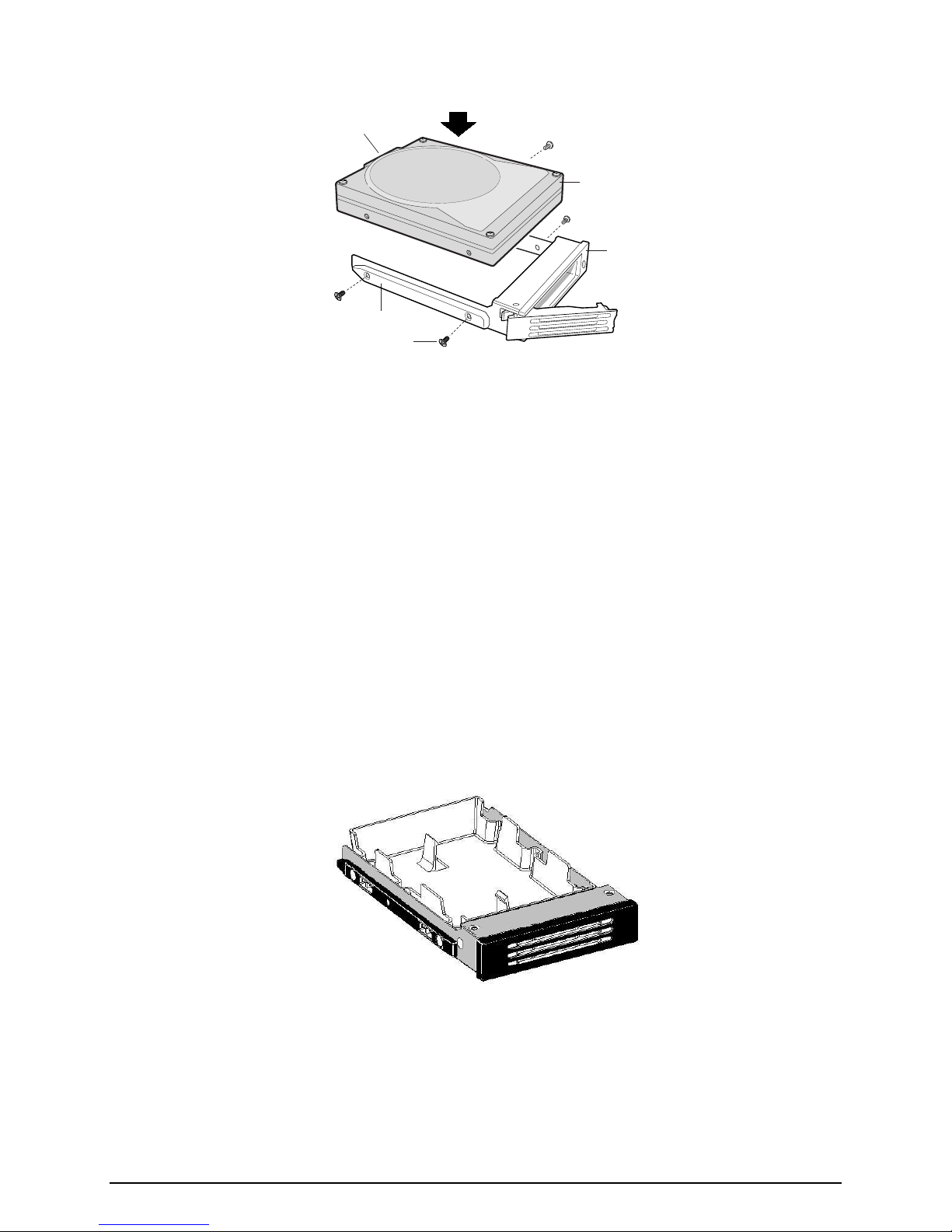
3.2.1 Hot-Swap Hard Disk Drive Trays
In a hot-swap configuration, each hard drive must be mounted to a hot-swap drive tray, making
insertion and extraction of the drive from the chassis very simple. Each drive tray has its own
dual purpose latching mechanism which is used to both insert and extract drives from the
chassis and lock the tray in place. Each drive tray supports a light pipe providing a drive status
indicator, located on the backplane, that is viewable from the front of the chassis.
Note: Depending on the controller used, SATA hard disk drives may not report errors using the
drive’s status indicator.
Revision 1.0 - 28 -
Page 29
Intel® Server Chassis SR1475 / Intel® Server System SR1475NH1-E
E
A
C
D
OM11684
Figure 20. Hard Drive Tray Assembly
A. Hard Drive
B. Drive Carrier
C. Side Rail
D. Mounting Screw
E. Hard Drive Connector
B
3.2.2 Fixed Drive Trays
In a fixed drive configuration, each SATA/SCSI hard drive must be mounted to a non-hot-swap
drive tray. The tray is designed to slide into the drive bay and lock into place. To remove the
drive, the chassis top cover must be removed to disengage the drive tray latch from the bay.
3.2.3 Drive Blanks
Drive blanks must be used when no drive is used in a hard drive bay. Drive blanks simulate the
spatial volume of a hard disk which is required to maintain proper air pressure limits necessary
to cool the system.
Revision 1.0 - 29 -
Figure 21. Drive Tray with Drive Blank
Page 30
Intel® Server Chassis SR1475 / Intel® Server System SR1475NH1-E
3.3 Hot-Swap SCSI Backplane
The Intel® Server Chassis SR1475 SCSI hot-swap backplane (HSBP) supports the following
feature set:
QLogic* GEM359 enclosure management controller
o External non-volatile Flash ROM
2
C interface
o I
o Low Voltage Differential (LVD) SCSI Interface
o SCSI-3 compatible
o Compliance with SCSI Accessed Fault Tolerant Enclosures (SAF-TE) specification,
version 1.00 and addendum
Support for up to three U320 LVD SCSI Drives
o Onboard LVD SCSI Termination – SPI-4 compatible
Hard drive status LEDs
One 2x3-pin power connector
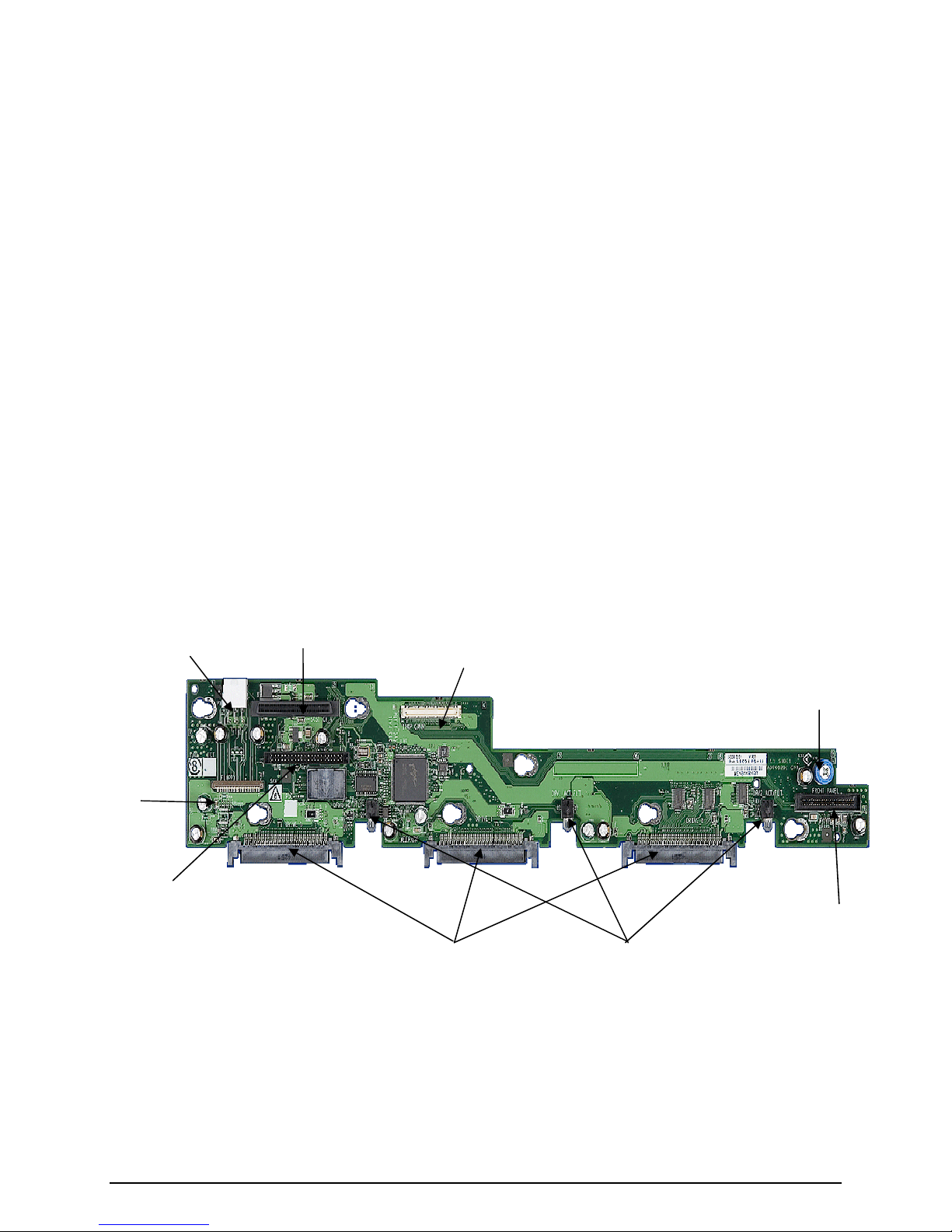
3.3.1 SCSI Backplane Board Layout
The following diagram shows the layout of the major components and connectors on the board.
Floppy drive
connector
(not used in
®
Server
Intel
Chassis
SR1475)
IDE connector
(not used in Intel®
Server Chassis
SR1475)
Power
connector
SCSI connector
to SCSI add-in
card
100-pin
connector
used in Intel
Server Chassis
SR1475)
SCA2 SCSI
hard drive
connectors
(not
®
Drive status
LEDs
Thumb
screw
Control panel
connector
used in Intel
Server Chassis
SR1475)
(not
®
Revision 1.0 - 30 -
Figure 22. SCSI Backplane Layout
Page 31
Intel® Server Chassis SR1475 / Intel® Server System SR1475NH1-E
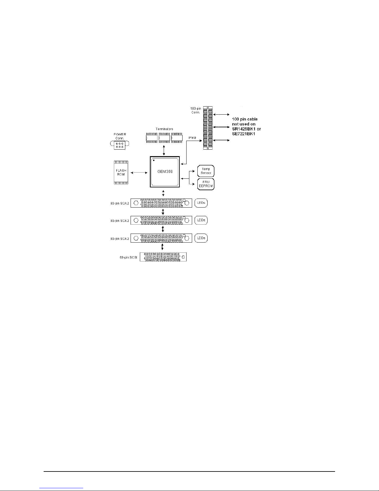
3.3.2 SCSI Backplane Functional Architecture
This section provides a high-level description of the functionality distributed between the
architectural blocks of the SCSI backplane. The following figure shows the functional blocks of
the SCSI backplane.
Figure 23. SCSI Backplane Functional Diagram
3.3.2.1 Enclosure Management Controller
The SCSI backplane utilizes the features of the QLogic* GEM359 for enclosure management
which monitors various aspects of a storage enclosure. The chip provides in-band SAF-TE and
SES management through the SCSI interface. Also supported is the I2C connection to the
server board.
The GEM359 comes in a 144-pin low profile Quad Flat Pack package and operates from 3.3V
and an input clock frequency of 10MHz. It has general input and output pins that allow
customization, some of which are used for drive detection and power controller enable/disable
functionality.
Revision 1.0 - 31 -
Page 32

Intel® Server Chassis SR1475 / Intel® Server System SR1475NH1-E
3.3.2.2 SCSI Interface
The GEM359 supports LVD SCSI operation through 8-bit asynchronous SCSI data transfers.
The following SCSI command set is supported:
Inquiry
Read Buffer
Write Buffer
Test Unit Ready
Request Sense
Send Diagnostic
Receive Diagnostic
The GEM359 supports the following SAF-TE command set:
Read Enclosure Configuration
Read Enclosure Status
Red Device Slot Status
Read Global Flags
Write Device Slot Status
Perform Slot Operation
3.3.2.3 I2C Serial Bus Interface
The GEM359 supports two independent I2C interface ports with bus speeds of up to 400Kbits.
The I2C core incorporates 8-bit FIFOs for data transfer buffering. The Intelligent Platform
Management Bus (IPMB) is supported through I2C port 1.
The following figure provides a block diagram of the I2C bus connection implemented on the
SCSI backplane.
Revision 1.0 - 32 -
Page 33

Intel® Server Chassis SR1475 / Intel® Server System SR1475NH1-E
Figure 24. Intel® Server Chassis SR1475 SCSI HSBP I2C Bus Connection Diagram
3.3.2.4 External Memory Device
The SCSI backplane contains a non-volatile 16K top boot block, 4Mbit Flash memory device
that stores the configuration data and operating firmware executed by the GEM359’s internal
CPU.
The Flash memory operates off the 3.3V rail and is housed in a 48-pin TSOP type 1 package.
3.3.2.5 LED Support
The SCSI backplane contains a green activity LED and a yellow fault LED for each of the three
hard drive connectors. The SCSI HDD drives the activity LED whenever the drive is accessed.
The GEM359 controller drives the fault LED whenever an error condition is detected.
Revision 1.0 - 33 -
Page 34

Intel® Server Chassis SR1475 / Intel® Server System SR1475NH1-E
3.3.3 SCSI Backplane Connector Definitions
As a multi-functional board, several connectors can be found on the SCSI backplane. This
section defines the purpose and pin-out associated with each connector.
3.3.3.1 Power Connector (Backplane to Power Supply Harness)
The SCSI backplane provides power to the three drive bays, supporting up to three hard disk
drives, and the slim-line drive bay, supporting one floppy drive or CD-ROM drive. A 6-pin power
cable is routed from the power distribution board and plugs into a 2 x 3 shrouded plastic PC
power connector on the SCSI backplane. The following table shows the power connector pinout.
Table 9. SCSI Backplane Power Connector Pin-out (J1)
Pin Name Pin Name
1 GND 4 P12V
2 GND 5 P12V
3 P5V 6 P5V_STBY
3.3.3.2 SCSI Connector (Backplane to SCSI Add-in Card)
A 68-pin SCSI cable is used to interface the SCSI backplane with an add-in PCI SCSI controller
installed on the PCI riser card.
Figure 25. 68-Pin SCSI Cable Connector
Revision 1.0 - 34 -
Page 35

Intel® Server Chassis SR1475 / Intel® Server System SR1475NH1-E
Table 10. UltraWide (SE) and Ultra2 (LVD) Ultra320 SCSI Connector Pin-out (J8)
Name Pin Pin Name
BP_SCSI_D12P A1 B1 BP_SCSI_D12N
BP_SCSI_D13P A2 B2 BP_SCSI_D13N
BP_SCSI_D14P A3 B3 BP_SCSI_D14N
BP_SCSI_D15P A4 B4 BP_SCSI_D15N
BP_SCSI_DP1P A5 B5 BP_SCSI_DP1N
BP_SCSI_D0P A6 B6 BP_SCSI_D0N
BP_SCSI_D1P A7 B7 BP_SCSI_D1N
BP_SCSI_D2P A8 B8 BP_SCSI_D2N
BP_SCSI_D3P A9 B9 BP_SCSI_D3N
BP_SCSI_D4P A10 B10 BP_SCSI_D4N
BP_SCSI_D5P A11 B11 BP_SCSI_D5N
BP_SCSI_D6P A12 B12 BP_SCSI_D6N
BP_SCSI_D7P A13 B13 BP_SCSI_D7N
BP_SCSI_DP0P A14 B14 BP_SCSI_DP0N
GND A15 B15 GND
BP_SCSI_DIFSNS A16 B16 GND
TERMI_PWR A17 B17 TERMI_PWR
TERMI_PWR A18 B18 TERMI_PWR
Unused A19 B19 Unused
GND A20 B20 GND
BP_SCSI_ATNP A21 B21 BP_SCSI_ATNN
GND A22 B22 GND
BP_SCSI_BSYP A23 B23 BP_SCSI_BSYN
BP_SCSI_ACKP A24 B24 BP_SCSI_ACKN
BP_SCSI_RSTP A25 B25 BP_SCSI_RSTN
BP_SCSI_MSGP A26 B26 BP_SCSI_MSGN
BP_SCSI_SELP A27 B27 BP_SCSI_SELN
BP_SCSI_CDP A28 B28 BP_SCSI_CDN
BP_SCSI_REQP A29 B29 BP_SCSI_REQN
BP_SCSI_IOP A30 B30 BP_SCSI_ION
BP_SCSI_D8P A31 B31 BP_SCSI_D8N
BP_SCSI_D9P A32 B32 BP_SCSI_D9N
BP_SCSI_D10P A33 B33 BP_SCSI_D10N
BP_SCSI_D11P A34 B34 BP_SCSI_D11N
Revision 1.0 - 35 -
Page 36

Intel® Server Chassis SR1475 / Intel® Server System SR1475NH1-E
3.3.3.3 SCA2 Hot-Swap SCSI Drive Connectors
The SCSI backplane provides three hot-swap SCA2 connectors, which provide power and SCSI
signals using a single connector. Each SCA drive attaches to the backplane using one of these
connectors.
Figure 26. 80-pin SCA2 SCSI Interface
Table 11. 80-pin SCA2 SCSI Interface Pin-out
Signal Name Pin Pin Signal Name
GND 41 1 P12V
GND 42 2 P12V
GND 43 3 P12V
SCSI_MATED 44 4 P12V
NC_3V_CHG 45 5 NC_3V_1
BP_SCSI_DIFSNS 46 6 NC_3V_2
BP_SCSI_D11P 47 7 BP_SCSI_D11N
BP_SCSI_D10P 48 8 BP_SCSI_D10N
BP_SCSI_D9P 49 9 BP_SCSI_D9N
BP_SCSI_D8P 50 10 BP_SCSI_D8N
BP_SCSI_IOP 51 11 BP_SCSI_ION
BP_SCSI_REQP 52 12 BP_SCSI_REQN
BP_SCSI_CDP 53 13 BP_SCSI_CDN
BP_SCSI_SELP 54 14 BP_SCSI_SELN
BP_SCSI_MSGP 55 15 BP_SCSI_MSGN
BP_SCSI_RSTP 56 16 BP_SCSI_RSTN
BP_SCSI_ACKP 57 17 BP_SCSI_ACKN
BP_SCSI_BSYP 58 18 BP_SCSI_BSYN
BP_SCSI_ATNP 59 19 BP_SCSI_ATNN
BP_SCSI_DP0P 60 20 BP_SCSI_DP0N
BP_SCSI_D7P 61 21 BP_SCSI_D7N
BP_SCSI_D6P 62 22 BP_SCSI_D6N
BP_SCSI_D5P 63 23 BP_SCSI_D5N
BP_SCSI_D4P 64 24 BP_SCSI_D4N
BP_SCSI_D3P 65 25 BP_SCSI_D3N
BP_SCSI_D2P 66 26 BP_SCSI_D2N
BP_SCSI_D1P 67 27 BP_SCSI_D1N
BP_SCSI_D0P 68 28 BP_SCSI_D0N
BP_SCSI_DP1P 69 29 BP_SCSI_DP1N
BP_SCSI_D15P 70 30 BP_SCSI_D15N
Revision 1.0 - 36 -
Page 37

Intel® Server Chassis SR1475 / Intel® Server System SR1475NH1-E
Signal Name Pin Pin Signal Name
BP_SCSI_D14P 71 31 BP_SCSI_D14N
BP_SCSI_D13P 72 32 BP_SCSI_D13N
BP_SCSI_D12P 73 33 BP_SCSI_D12N
SCSI_MATED 74 34 P5V
GND 75 35 P5V
GND 76 36 P5V
HD_ACT_LED_L 77 37 Unused
Unused 78 38 GND
Unused 79 39 Unused
Unused 80 40 Unused
GND B2 B1 GND
3.4 Hot-Swap SATA Backplane
The Intel® Server Chassis SR1475 SATA hot-swap backplane (HSBP) supports the following
feature set:
QLogic* GEM424 enclosure management controller
o External non-volatile SEEPROMs
o SATA and SATA-II extension compatible
o Compliance with SATA Accessed Fault Tolerant Enclosures (SAF-TE) specification,
version 1.00 and addendum
o Compliance with Intelligent Platform Management Interface 1.5 (IPMI)
Support for up to three SATA drives
Hot-Swap drive support
One 2 x 3-pin power connector
IDE Connector provided for slim-line CD-ROM or DVD support
Drive Status LEDs
Revision 1.0 - 37 -
Page 38

Intel® Server Chassis SR1475 / Intel® Server System SR1475NH1-E
3.4.1 SATA Backplane Layout
The SATA backplane is located on the backside of the hot-swap drive bays on the inside of the
chassis. Stand-offs on the chassis and a single thumb screw make for easy tool-less
installation. The following diagram shows the layout of the major components and connectors of
the board.
Floppy drive
connector (not used in
®
Intel
Server Chassis
SR1475)
SATA drive
connectors
Power connector IDE connector
used in Intel
®
Server
Figure 27. SATA Backplane Layout
Drive status LEDs
Figure 28. SATA Backplane Layout
(not
100-pin connector (not
used in Intel
Chassis SR1475)
®
Server
SATA connectors
Control panel
connector (not used in
®
Intel
Server Chassis
SR1475)
Revision 1.0 - 38 -
Page 39

Intel® Server Chassis SR1475 / Intel® Server System SR1475NH1-E
3.4.2 SATA Backplane Functional Architecture
This section provides a high-level description of the functionality distributed between the
architectural blocks of the SATA backplane. The following figure shows the functional blocks of
the SATA backplane.
Figure 29. SATA Backplane Functional Block Diagram
3.4.2.1 Enclosure Management Controller
The SATA backplane utilizes the features and functionality of the QLogic* GEM424 enclosure
management controller, which is capable of monitoring various aspects of a storage enclosure.
The chip provides in-band SAF-TE management through the SATA Host I2C interface.
The GEM424 comes in an 80-pin Thin Quad Flat Pack (TQFP) package and operates from 3.3V
and an input clock frequency of 20MHz. It has general input and output pins that are used for
hardware drive detection and driving fault and activity LEDs.
Revision 1.0 - 39 -
Page 40

Intel® Server Chassis SR1475 / Intel® Server System SR1475NH1-E
3.4.2.2 SATA Interface
The GEM424 implements SAF-TE over the HBA I2C interface. The GEM424 supports the
following SAF-TE command set:
Read Enclosure Configuration
Read Enclosure Status
Read Device Slot Status
Read Global Flags
Write Device Slot Status
Perform Slot Operation
3.4.2.2.1 I2C Serial Bus Interface
The GEM424 supports two independent I2C interface ports with bus speeds of up to 400Kbits.
The I2C core incorporates 8-bit FIFOs for data transfer buffering. The Intelligent Platform
Management Bus (IPMB) is supported through I2C port 0.
The figure below provides a block diagram of I2C bus connection implemented on SATA
backplane.
Figure 30. Intel® Server Chassis SR1475 SATA HSBP I2C Bus Connection Diagram
Revision 1.0 - 40 -
Page 41

Intel® Server Chassis SR1475 / Intel® Server System SR1475NH1-E
3.4.2.3 External Memory Device
The SATA backplane contains non-volatile 32K and 64K serial EEPROM devices for boot and
run-time/configuration code storage respectively. These devices reside on the GEM424’s
private I2C bus.
The SEEPROMs operate off the 5.0V rail and are housed in 8-pin SOIC packages.
3.4.2.4 LED Support
The SATA backplane contains a green activity LED and an amber fault LED for each of the
three hard drive connectors. The activity LED is driven by the GEM424 or, for drives that
support the feature, by the SATA HDD whenever the drive is accessed. The fault LED is driven
by the GEM424 controller whenever an error condition is detected, as defined by the firmware.
Activity and fault LED functions are only available when a SATA host controller that supports the
SAF-TE protocol over I2C is connected to the SATA backplane via the SATA Host I2C
connector, J2A3.
Table 12. LED Function
Status LED Definition
Green ON HDD Activity
Amber ON HDD Fail
Amber Blinking Rebuild in progress
3.4.3 SATA Backplane Connector Definitions
3.4.3.1 Power Connector
The SATA backplane provides power for up to three SATA drives, and one floppy drive or CDROM drive. A 6-pin power cable from the power supply harness is routed to the backplane and
plugs into a 2x3 shrouded plastic PC power connector. The following table provides the
connector pin-out.
Table 13. SATA Backplane Power Connector Pin-out
Pin Name Pin Name
1 GND 4 P12V
2 GND 5 P12V
3 P5V 6 P5V_STBY
Revision 1.0 - 41 -
Page 42
Intel® Server Chassis SR1475 / Intel® Server System SR1475NH1-E
3.4.3.2 SATA Connectors (Backplane to Server Board)
The SATA backplane has three 7-pin SATA connectors (Drive0, Drive1 and Drive2). These
connectors correspond to the SATA connectors on the Intel
®
Server Board SE7230NH1-E
(SATA1, SATA2 and SATA3). The backplane connectors relay SATA signals from the server
board to the SATA drives. Each connector is used for a separate SATA channel and is
configured as a bus master. The following table provides the connector pin-out.
Table 14. 7-Pin SATA Connector Pin-out (J2, J3, J4, J5, J6)
Pin Name
1 GND
2 DRV_RX_P
3 DRV_RX_N
4 GND
5 DRV_TX_P
6 DRV_TX_N
7 GND
8 GND
9 GND
3.4.3.3 Hot-Swap SATA Drive Connectors
The SATA drive interface combines both SATA and power signals into a single connector. The
pin-out of the drive interface connector is the same as a standard SATA and power connector.
The following table provides the pin-out.
Table 15. 22-Pin SATA Connector Pin-out
Name Pin Pin Name
GND 1 13 GND
DRV_RX_P 2 14 SCSI+5V
DRV_RX_N 3 15 SCSI+5V
GND 4 16 SCSI+5V
DRV_TX_P 5 17 GND
DRV_TX_N 6 18 Unused
GND 7 19 GND
P3V3 8 20 SCSI+12V
P3V3 9 21 SCSI+12V
P3V3 10 22 SCSI+12V
GND 11 23 GND
GND 12 24 GND
3.4.3.4 Slim-line Floppy Drive Connector
With a slim-line floppy drive installed into either the slim-line drive bay or in one of the hard drive
bays (using the optionally installed floppy drive kit), the floppy cable from the drive is routed to
the legacy floppy connector on the server board.
Revision 1.0 - 42 -
Page 43

Intel® Server Chassis SR1475 / Intel® Server System SR1475NH1-E
3.4.3.5 Slim-line CD-ROM / DVD Interface Assembly
When a CD-ROM or DVD drive is installed into the slim-line peripheral bay, the drive cable is
routed from a connector on the drive interposer card, to the server board legacy IDE connector.
Revision 1.0 - 43 -
Page 44

Intel® Server Chassis SR1475 / Intel® Server System SR1475NH1-E
4. Standard Control Panel
The standard control panel supports several push buttons and status LEDs, along with USB and
video ports to centralize system control, monitoring, and accessibility to within a common
compact design.
The control panel assembly comes pre-assembled and is modular in design. The control panel
assembly module slides into a predefined slot on the front of the chassis. Once installed,
communication to the server board can be achieved by either attaching a 50-pin cable to a hotswap backplane, or if fixed drives are used, can be connected directly to the server board. In
addition, a USB cable is routed to the USB port on the server board.
Figure 31. Standard Control Panel Assembly Module
4.1 Standard Control Panel Buttons
The standard control panel assembly houses several system control buttons. Each of their
functions is listed in the table below.
Figure 32. Standard Control Panel Buttons
Revision 1.0 - 44 -
Page 45

Intel® Server Chassis SR1475 / Intel® Server System SR1475NH1-E
y
y
Table 16. Standard Control Panel Button Functions
Reference Feature Function
A Power /
Sleep Button
B ID Button Toggles the front panel ID LED and the baseboard ID LED on/off. The
C Reset Button Reboots and initializes the system.
D NMI Button Pressing the recessed button with a paper clip or pin puts the server in a
Toggles the system power on/off. This button also functions as a Sleep
Button if enabled by an ACPI-compliant operating system.
baseboard ID LED is visible through the rear of the chassis and allows you
to locate the server you’re working on from behind a rack of servers.
halt state for diagnostic purposes and allows you to issue a non-maskable
interrupt. After issuing the interrupt, a memory download can be performed
to determine the cause of the problem.
4.2 Standard Control Panel LED Indicators
The standard control panel houses six LEDs, which are viewable with or without the front bezel
to display the system’s operating state.
NIC1 and NIC2
LEDs
Activit
Figure 33. Control Panel LEDs
Power and
Sleep LED
Not Used
LED
Hard Drive
LED
Activit
System
Identify LED
Revision 1.0 - 45 -
Page 46
Intel® Server Chassis SR1475 / Intel® Server System SR1475NH1-E
The following table identifies each LED and describes their functionality.
Table 17. Standard Control Panel LED Functions
LED Color State Description
Green On NIC Link NIC1 / NIC2
Activity
Power / Sleep
(on standby power)
Disk Activity
System Identification
Notes:
1. Blink rate is ~1 Hz with at 50% duty cycle.
2. The amber status takes precedence over the green status. When the amber LED is on or blinking, the green
LED is off.
3. Also off when the system is powered off (S4/S5) or in a sleep state (S1).
4. The power LED sleep indication is maintained on standby by the chipset. If the system is powered down
without going through BIOS, the LED state in effect at the time of power off will be restored when the system
is powered on until the BIOS clears it. If the system is not powered down normally, it is possible that the
Power LED will be blinking at the same time that the system status LED is off due to a failure or
configuration change that prevents the BIOS from running.
Green Blink NIC Activity
On Legacy power on / ACPI S0 state Green
1,4
Blink
Off Off Power Off / ACPI S4 or S5 state
Green Random
blink
Off Off
Blue Blink Identify active via command or button.
Off Off No Identification.
Sleep / ACPI S1 state
Provides an indicator for disk activity.
3
No hard disk activity
The current limiting resistors for the power LED and the NIC LEDs are located on the Intel
®
Server Board SE7230NH1-E.
4.2.1 Power / Sleep LED
Table 18. SSI Power LED Operation
State Power Mode LED Description
Power Off Non-ACPI Off System power is off, and the BIOS has not initialized the chipset.
Power On Non-ACPI On System power is on, but the BIOS has not yet initialized the chipset.
S5 ACPI Off Mechanical is off, and the operating system has not saved any context
to the hard disk.
S4 ACPI Off Mechanical is off. The operating system has saved context to the hard
disk.
S3-S1 ACPI Slow blink 1 DC power is still on. The operating system has saved context and
gone into a level of low-power state.
S0 ACPI Steady on System and the operating system are up and running.
Notes:
1. Blink rate is ~ 1Hz with at 50% duty cycle.
4.2.2 Drive Activity LED
The drive activity LED on the front panel indicates drive activity from the onboard hard disk
controllers. The server board also provides a header giving access to this LED for add-in
controllers.
Revision 1.0 - 46 -
Page 47
Intel® Server Chassis SR1475 / Intel® Server System SR1475NH1-E
4.2.3 System Identification LED
The blue system identification LED is used to help identify a system for servicing. This is
especially useful when the system is installed in a high density rack or cabinet that is populated
with several similar systems. The system ID LED will blink when the System ID button on the
control panel is pressed, or it can be illuminated remotely through server management software.
4.3 Control Panel Connectors
The control panel has one external I/O connector:
• One USB port
The following tables provide the pin-outs for the connector.
Table 19. External USB Connector (J2)
Pin # Description
1 PWR_FP_USB2
2 USB_DN2_FP_R
3 USB_DP2_FP_R
4 GND
5 GND
6 GND
7 GND
4.4 Internal Control Panel Assembly Headers
The control panel interface board has two internal headers.
• A 50-pin header provides control and status information to and from the server board.
Using a 50-pin flat cable, the header is connected to a matching SSI connector on the
server board.
• A 10-pin header is used to provide USB support to the control panel. The round 10-pin
cable is routed from the control panel assembly to a matching connector on the server
board.
Revision 1.0 - 47 -
Page 48

Intel® Server Chassis SR1475 / Intel® Server System SR1475NH1-E
The following tables provide the pin-outs for both types of connectors.
Table 20. 50-pin Control Panel Connector (J3)
Description Pin # Pin # Description
PWR_LCD_5VSB 2 1 PWR_LCD_5VSB
HDD_LED_ACT_R_L 4 3 Unused
RST_P6_PWRGOOD 6 5 FP_SYS_FLT_LED1_R_L
P5V_STBY 8 7 FP_SYS_FLT_LED2_R_L
FP_PWR_LED_R_L 10 9 P5V_STBY
IPMB_5VSB_SDA 12 11 P3V3
IPMB_5VSB_SCL 14 13 GND
FP_PWR_BTN_L 16 15 FP_ID_LED_R_L
HDD_FAULT_LED_R_L 18 17 NIC2_LINK_LED_R_L
FP_RST_BTN_L 20 19 NIC2_ACT_LED_L
GND 22 21 BP_I2C_5V_SDA
FP_ID_SW_L 24 23 BP_I2C_5V_SCL
NIC1_ACT_LED_L 26 25 FP_CHASSIS_L
FP_NMI_BTN_L 28 27 NIC1_LINK_LED_R_L
EMP_DSR2_L 30 29 GND
EMP_SIN2 32 31 EMP_INUSE_L
EMP_RTS2_L 34 33 EMP_SOUT2
EMP_DTR2_L 36 35 EMP_CTS2_L
VGA_INUSE_L 38 37 EMP_DCD2_L
VGA_VSYNC_FP_L 40 39 1_WIRE_BUS
VGA_HSYNC_FP_L 42 41 GND
VGA_BLUE_FP 44 43 GND
VGA_GREEN_FP 46 45 GND
VGA_RED_FP 48 47 GND
50 49 GND
Table 21. Internal USB Header (J9F2)
Pin # Description
1 PWR_FP_USB2
2 PWR_FP_USB3
3 USB_DP2_FP
4 USB_DN2_FP
5 USB_DP3_FP
6 USB_DN3_FP
7 GND
8 GND
9 TP_USB0_P9
10 TP_USB0_P10
Revision 1.0 - 48 -
Page 49

Intel® Server Chassis SR1475 / Intel® Server System SR1475NH1-E
5. PCI Riser Cards and Assembly
The Intel® Server Board SE7230NH1-E provides one PCI riser slot (Intel® Adaptive Slot),
supporting full height/full length add-in card risers. The riser slot is capable of supporting risers
that follow either the PCI-X* or PCI Express* specifications. The riser assembly for the server
chassis consists of a single bracket with three threaded mounting holes: two on the long arm of
the bracket secure the riser card to the bracket; a third is used to secure the add-in card to the
riser. Tabs on the rear of the riser bracket allow the riser card to safely mate with the chassis
even when no riser card is installed.
Note: Ensure the riser bracket is seated securely in the chassis before applying power as
damage to the server board may occur if the metal bracket comes in contact with components.
Figure 34. PCI Riser Bracket and Optional PCI-X* and PCI Express* Risers
Revision 1.0 - 49 -
Page 50

Intel® Server Chassis SR1475 / Intel® Server System SR1475NH1-E
5.1 Riser Card Options
There are two different riser card options offered for use in the Intel® Server Chassis SR1475.
• PCI-X* – capable of supporting a single full height/full length PCI-X* 66/100 MHz add-in
card.
• PCI Express* – capable of supporting a single full height/full length x8 PCI Express*
add-in card.
Figure 35. 1U Full Height PCI-X* Riser Card Mechanical Drawing
Figure 36. 1U Full Height PCI Express* Riser Card Mechanical Drawing
Revision 1.0 - 50 -
Page 51

Intel® Server Chassis SR1475 / Intel® Server System SR1475NH1-E
6. Power Sub-system
The power sub-system of the server chassis consists of a single non-redundant 350 W power
supply with 7 outputs; 3.3V, 5V, 12V1, 12V2, 12V3, -12V and 5VSB. The form factor fits into a
1U system and provides a wire harness output to the system. An IEC connector is provided on
the external face for AC input to the power supply. The power supply provides two nonredundant 40mm fans for self cooling. The power supply fans also provide additional airflow for
parts of the system.
6.1 Mechanical Specifications
The 1U 350 W power supply is designed specifically for use in the Intel® Server Chassis
SR1475. The physical size of the power supply enclosure is intended to accommodate power
ranges from 350 W. The power supply size is 40mm x 106mm x 300mm and has a wire
harness for the DC outputs. The AC input plugs directly into the external face of the power
supply; refer to the following figure.
Figure 37. Power Supply Enclosure Drawing
Notes:
1. All dimensions are in mm.
2. The tolerance of the 40mm height dimension (marked with letter C) pertains to the metal case
only.
Revision 1.0 - 51 -
Page 52

Intel® Server Chassis SR1475 / Intel® Server System SR1475NH1-E
6.2 Airflow Requirements
The power supply shall incorporate two 40mm fans for self-cooling and system cooling. The
fans will provide no less than 8 CFM airflow through the power supply when installed in the
system. The cooling air will enter the power supply module from the non-AC side.
System Flow Impedance - 1U
0.7
0.6
O)
2
0.5
0.4
0.3
0.2
System Pressure (in H
0.1
0.0
0 2 4 6 8 10 12 14 16 18
Power Su pply Airflow (CFM )
Figure 38. Airflow Characteristics
6.3 Acoustics
The power supply shall incorporate two variable speed fans. The fans speed shall vary linearly
based on output loading and ambient temperature. The declared sound power levels (LwAd) of
the power supply unit (PSU) must meet the requirements shown in the following table. Sound
power must be measured according to ECMA 74 (www.ecma-international.org
according to ISO 9296.
The acoustic measurement of the PSU shall be performed with the PSU fan operating at the
RPM corresponding to the operating conditions shown in the following table. The PSU acoustic
test report shall include the PSU dimension, photo, fan model and size, fan voltage (or duty
cycle), RPM and PSU sound power level at each operating condition. The proper RPM
thermally sustainable shall be determined through PSU thermal testing, and shall be submitted
as an appendix to the acoustic test report.
) and reported
The declared sound power level of the power supply module shall not exceed the levels
specified in the following table.
Revision 1.0 - 52 -
Page 53

Intel® Server Chassis SR1475 / Intel® Server System SR1475NH1-E
Table 22. Acoustic Requirements
Operating Conditions Inlet Temperature
Condition
Maximum
Operating
Idle
Standby (main outputs off)
45ºC 100% 6.5
28°C
28°C
28°C
% of Maximum Loading
Condition
60% 5.6
40% 5.4
5Vsb/2A < 5.4
LwAd (BA)
6.4 Temperature
The power supply shall operate within all specified limits over the Top temperature range. The
average air temperature difference (ΔTps ) from the inlet to the outlet of the power supply shall
not exceed 20°C. All airflow shall pass through the power supply and not over the exterior
surfaces of the power supply.
Table 23. Environmental Requirements
ITEM DESCRIPTION MIN MAX UNITS
Top
T
non-op
Altitude
The power supply must meet UL enclosure requirements for temperature rise limits. All sides of
the power supply with exception to the air exhaust side must be classified as “handle, knobs,
grips, etc. held for short periods of time only”.
Operating temperature range. 0 45
Non-operating temperature range. -40 70
Maximum operating altitude. 1500 m
°C
°C
6.5 Output Connectors
Listed or recognized component appliance wiring material (AVLV2), CN, rated min 80°C,
300VDC shall be used for all output wiring.
Table 24. Cable Lengths
From
Power Supply cover exit hole 400 P1 20 Baseboard Power Connector
Power Supply cover exit hole 665 P2 8 Processor Power Connector
Power Supply cover exit hole 160 P3 6 HD Power Connector
Power Supply cover exit hole 140 P4 4 Slim-line Power Connector
Length
(mm)
To
connector
#
No of
pins
Description
Revision 1.0 - 53 -
Page 54

Intel® Server Chassis SR1475 / Intel® Server System SR1475NH1-E
6.5.1 P1 Main power connector
Connector housing: 20-Pin Molex* Mini-Fit Jr. 39-01-2200 or equivalent.
Contact: Molex Mini-Fit, HCS, female, crimp 44476 or Molex 5556 as the alternative, or
equivalent approved by Intel.
Table 25. P1 Main Power Connector
Pin Signal 18 AWG Color Pin Signal 18 AWG Color
1 +3.3VDC
3.3V RS Orange/White (24AWG) 12 -12VDC Blue
2 +3.3VDC Orange 13 COM Black
3 COM Black 14 PSON# Green (24AWG)
4 +5VDC Red 15 COM
5 COM Black COMRS Black (24AWG)
6 +5VDC Red 16 COM Black
7 COM Black 17 COM Black
8 PWR OK Gray (24AWG) 18 Reserved N.C.
9 5 VSB Purple 19 +5VDC Red
10 +12V Yellow 20 +5VDC Red
12VRS Yellow/White (24AWG) 5VRS Red/White (24AWG)
Notes:
Orange 11 +3.3VDC Orange
1. Remote Sense wire double crimped.
2. P1 add cable bend requirement at P1.
Black
6.5.2 P2 Processor Power Connector
Connector housing: 8-Pin Molex* 39-01-2085 or equivalent.
Contact: Molex
44476-1111 or Molex 5556 as the alternative, or equivalent approved by Intel.
Pin Signal 18 AWG color Pin Signal 18 AWG Color
1 COM Black 5 +12V Yellow
2 COM Black 6 +12V Yellow
3 N.C. 7 N.C.
4 N.C. 8 N.C.
Revision 1.0 - 54 -
Table 26. P2 Processor Power Connector
Page 55

Intel® Server Chassis SR1475 / Intel® Server System SR1475NH1-E
6.5.3 HD Power Connector (P3)
Connector housing: 6-pin Molex* 39-01-2065 or equivalent.
Contacts: Molex Mini-Fit, (HCS or standard), female, crimp or equivalent.
Table 27. HD Power Connector
Pin Signal 18 AWG Color
1 COM Black
2 COM Black
3 +5VDC
4 +12VDC Yellow
5 +12VDC
6 +5Vsb Purple
6.5.4 Slim-line Power Connector (P4)
Connector housing: 4-pin Molex* 39-01-3042 or equivalent.
Contact: Molex
44476-1111 or Molex 5556 as the alternative, or equivalent approved by Intel.
Red
Yellow
Table 28. Slim-line Power Connector
PIN SIGNAL 18 AWG COLOR PIN SIGNAL 18 AWG COLOR
1 +12V Yellow 3 +5V Red
2 COM Black 4 COM Black
6.6 AC Inlet Connector
The AC input connector shall be an IEC 320 C-14 power inlet. This inlet is rated for 10A /
250VAC.
6.7 Marking and Identification
The power supply module marking supports the following requirements: safety agency
requirements, government requirements (if required, e.g. point of manufacturing), power supply
vendor requirements, and Intel manufacturing and field support requirements.
Revision 1.0 - 55 -
Page 56

Intel® Server Chassis SR1475 / Intel® Server System SR1475NH1-E
6.8 AC Input Voltage
The power supply must operate within all specified limits over the following input voltage range,
shown in table below. Harmonic distortion of up to 10% of the rated line voltage must not
cause the power supply to go out of specified limits. The power supply shall power off if the AC
input is less than 75VAC +/-5VAC range. The power supply shall start up if the AC input is
greater than 85VAC +/-4VAC. Application of an input voltage below 85VAC shall not cause
damage to the power supply, including a fuse blow.
Table 29. AC Input Rating
I
6 A
3 A
1, 3
2, 3
MAX
PARAMETER MIN RATED V
Voltage (110) 90 V
Voltage (220) 180 V
Frequency 47 Hz 50/60 63 Hz
Notes:
1. Maximum input current at low input voltage range shall be measured at 90VAC, at max load.
2. Maximum input current at high input voltage range shall be measured at 180VAC, at max load.
3. This requirement is not to be used for determining agency input current markings.
100-127 V
rms
200-240 V
rms
140 V
rms
264 V
rms
MAX
rms
rms
Start up
VAC
85VAC +/4VAC
Power Off
VAC
75VAC +/5VAC
6.9 AC Line Transient Specification
AC line transient conditions shall be defined as “sag” and “surge” conditions. “Sag” conditions
are also commonly referred to as “brownout”; these conditions will be defined as the AC line
voltage dropping below nominal voltage conditions. “Surge” will be defined to refer to conditions
when the AC line voltage rises above nominal voltage.
The power supply shall meet the requirements under the following AC line sag and surge
conditions.
Table 30. AC Line Sag Transient Performance
AC Line Sag
Duration Sag Operating AC Voltage Line
Frequency
Continuous 10% Nominal AC Voltage ranges 50/60Hz No loss of function or performance
0 to 1 AC
cycle
> 1 AC cycle >30% Nominal AC Voltage ranges 50/60Hz Loss of function acceptable, self
95% Nominal AC Voltage ranges 50/60Hz No loss of function or performance
recoverable
Performance Criteria
Revision 1.0 - 56 -
Page 57

Intel® Server Chassis SR1475 / Intel® Server System SR1475NH1-E
Table 31. AC Line Surge Transient Performance
AC Line Surge
Duration Surge Operating AC Voltage Line
Frequency
Continuous 10% Nominal AC Voltages 50/60Hz No loss of function or performance
0 to ½ AC
cycle
30% Mid-point of nominal AC
Voltages
50/60Hz No loss of function or performance
Performance Criteria
6.10 Susceptibility
The power supply meets the following electrical immunity requirements when connected to a
cage with an external EMI filter which meets the criteria defined in the SSI document EPS
Power Supply Specification. For further information on Intel standards please request a copy of
the Intel Environmental Standards Handbook.
Table 32. Performance Criteria
Level Description
A The apparatus continues to operate as intended. No degradation of performance.
B The apparatus continues to operate as intended. No degradation of performance beyond
spec limits.
C Temporary loss of function is allowed provided the function is self-recoverable or can be
restored by the operation of the controls.
6.10.1 Electrostatic Discharge Susceptibility
The power supply complies with the limits defined in EN 55024: 1998 using the IEC 61000-42:1995 test standard and performance criteria B defined in Annex B of CISPR 24.
6.10.2 Fast Transient/Burst
The power supply complies with the limits defined in EN55024: 1998 using the IEC 61000-44:1995 test standard and performance criteria B defined in Annex B of CISPR 24.
6.10.3 Radiated Immunity
The power supply complies with the limits defined in EN55024: 1998 using the IEC 61000-43:1995 test standard and performance criteria A defined in Annex B of CISPR 24.
6.10.4 Surge Immunity
The power supply was tested with the system for immunity to AC ringwave and AC
unidirectional wave, both up to 2kV, per EN 55024:1998, EN 61000-4-5:1995 and ANSI C62.45:
1992. The pass criteria includes: no unsafe operation exists under any condition; all power
supply output voltage levels remain within proper spec levels; no change in operating state or
loss of data was detected during and after the test profile; no component damage occurred
under any condition.
Revision 1.0 - 57 -
Page 58
Intel® Server Chassis SR1475 / Intel® Server System SR1475NH1-E
The power supply complies with the limits defined in EN55024: 1998 using the IEC 61000-45:1995 test standard and performance criteria B defined in Annex B of CISPR 24.
6.11 AC Line Fast Transient (EFT) Specification
The power supply meets the EN61000-4-5 directive and any additional requirements in
IEC1000-4-5:1995 and the level 3 requirements for surge-withstand capability, with the following
conditions and exceptions:
• These input transients do not cause any out-of-regulation conditions, such as overshoot
and undershoot, nor any nuisance trips of any of the power supply protection circuits.
• The surge-withstand does not produce damage to the power supply.
The supply meets surge-withstand test conditions under maximum and minimum DC-output
load conditions.
6.12 AC Line Dropout / Holdup
An AC line dropout is defined to be when the AC input drops to 0VAC at any phase of the AC
line for any length of time. During an AC dropout the power supply must meet dynamic voltage
regulation requirements. An AC line dropout of any duration shall not cause tripping of control
signals or protection circuits. If the AC dropout lasts longer than the hold up time, the power
supply should recover and meet all turn on requirements. The power supply shall meet the AC
dropout requirement over rated AC voltages (100-240VAC) and frequencies. A dropout of the
AC line for any duration shall not cause damage to the power supply.
Table 33. Dropout Criteria
Loading Dropout time
350W (100%) 15msec
260W (75%) 20msec
6.12.1 AC Line 5VSB Holdup
The 5VSB output voltage should stay in regulation under its full load (static or dynamic) during
an AC dropout of 70ms / min (=5VSB holdup time) whether the power supply is in the ON or
OFF state (PSON asserted or de-asserted).
6.13 Power Recovery
The power supply shall recover automatically after an AC power failure. AC power failure is
defined to be any loss of AC power that exceeds the dropout criteria.
Revision 1.0 - 58 -
Page 59

Intel® Server Chassis SR1475 / Intel® Server System SR1475NH1-E
6.13.1 Voltage Brown Out
The power supply shall comply with the limits defined in EN55024: 1998 using the IEC 61000-411:1995 test standard and performance criteria C defined in Annex B of CISPR 24.
In addition the power supply shall meet the following Intel requirements:
A continuous input voltage below the nominal input range shall not damage the power supply or
cause overstress to any power supply component. The power supply must be able to return to
normal power up state after a brownout condition. Maximum input current under a continuous
brownout shall not blow the fuse. The power supply shall be tested with a 3 min ramp from
90VAC voltage to 0VAC after the components have reached a steady state condition.
6.13.2 Voltage Interruptions
The power supply shall comply with the limits defined in EN55024: 1998 using the IEC 61000-411:1995 and the level 3 requirements test standard and performance criteria C defined in Annex
B of CISPR 24.
6.14 AC Line Inrush
AC line inrush current shall not exceed 55 A peak, cold start at 20°C and no component
damaged at hot start for up to one-quarter of the AC cycle, after which, the input current should
be no more than the specified maximum input current. AC line inrush current may exceed 55 A
peak during hot start at 45°C. The peak inrush current shall be less than the ratings of its
critical components (including input fuse, bulk rectifiers, and surge limiting device).
The power supply must meet the inrush requirements for any rated AC voltage, during turn on at
any phase of AC voltage, during a single cycle AC dropout condition as well as upon recovery
after AC dropout of any duration, and over the specified temperature range (T
).
op
6.15 AC Line Isolation Requirements
The power supply shall meet all safety agency requirements for dielectric strength. Additionally,
the power supply vendor must provide Intel with written confirmation of the dielectric withstand
test which includes: voltage level, duration of test and identification detailing how each power
supply is marked to indicate the dielectric withstand test had been completed successfully.
Transformers’ isolation between primary and secondary windings must comply with the
3000Vac (4242Vdc) dielectric strength criteria. If the working voltage between primary and
secondary dictates a higher dielectric strength test voltage, the highest test voltage should be
used. In addition the insulation system must comply with reinforced insulation per safety
standard IEC 950. Separation between the primary and secondary circuits, and primary to
ground circuits, must comply with the IEC 950 spacing requirements.
6.16 AC Line Leakage Current
The maximum leakage current to ground for each power supply shall be 3.5 mA when tested at
240VAC.
Revision 1.0 - 59 -
Page 60

Intel® Server Chassis SR1475 / Intel® Server System SR1475NH1-E
6.17 AC Line Fuse
The power supply shall have one line fused in the single line fuse on the line (Hot) wire of the
AC input. The line fusing shall be acceptable for all safety agency requirements. The input fuse
shall be a slow blow type. AC inrush current shall not cause the AC line fuse to blow under any
conditions. All protection circuits in the power supply shall not cause the AC fuse to blow unless
a component in the power supply has failed. This includes DC output load short conditions.
6.18 Power Factor Correction
The power supply shall incorporate a Power Factor Correction circuit.
The power supply shall be tested as described in EN 61000-3-2: Electromagnetic Compatibility
(EMC) Part 3: Limits- Section 2: Limits for harmonic current emissions, and shall meet the
harmonic current emissions limits specified for ITE equipment.
The power supply shall be tested as described in JEIDA MITI Guideline for Suppression of High
Harmonics in Appliances and General-Use Equipment and shall meet the harmonic current
emissions limits specified for ITE equipment.
6.19 Efficiency
The power supply shall have a recommended efficiency of 70% at maximum load and over the
specified AC voltage.
6.20 Grounding
The output ground of the pins of the power supply provides the output power return path. The
output connector ground pins shall be connected to the safety ground (power supply enclosure).
This grounding should be well designed to ensure passing the max allowed common mode
noise levels.
The power supply shall be provided with a reliable protective earth ground. All secondary
circuits shall be connected to protective earth ground. Resistance of the ground returns to
chassis shall not exceed 1.0 mΩ. This path may be used to carry DC current.
6.21 Remote Sense
The power supply has remote sense return (ReturnS) to regulate out ground drops for all output
voltages: +3.3V, +5V, +12V, -12V, and 5VSB. The power supply uses remote sense to regulate
out drops in the system for the +3.3V, +5V, and 12V outputs. The power supply must operate
within specification over the full range of voltage drops from the power supply’s output
connector to the remote sense points.
Revision 1.0 - 60 -
Page 61
Intel® Server Chassis SR1475 / Intel® Server System SR1475NH1-E
6.22 Output Power / Currents
The following tables define two power and current ratings for this 350 W power supply. The
combined output power of all outputs shall not exceed the rated output power. The power
supply must meet both static and dynamic voltage regulation requirements for the minimum
loading conditions.
Table 34. Load Ratings
Voltage
4
+3.3V
4
+5V
+12V 1.5 A 24 A 28 A
-12V 0 A 0.3 A
+5VSB 0.1 A 2.0 A 2.5 A
Notes:
1. Maximum continuous total DC output power should not exceed 350W.
2. Peak total DC output power should not exceed 400W.
3. Peak power and peak current loading shall be supported for a minimum of 12 seconds.
4. Combined 3.3V/5V power shall not exceed 100W.
Minimum
Continuous Load
1.5 A 14 A
1.0 A 18 A
Maximum
Continuous Load
1, 3
Peak Load
2, 3
6.22.1 Standby Outputs
The 5VSB output shall be present when an AC input greater than the power supply turn on
voltage is applied.
6.22.2 Fan Operation in Stand-By Mode
The power supply fans shall continue to operate at their lowest speed when in stand-by mode.
6.23 Voltage Regulation
The power supply output voltages must stay within the following voltage limits when operating at
steady state and dynamic loading conditions. These limits include the peak-peak ripple/noise.
All outputs are measured with reference to the return remote sense signal (ReturnS).
PARAMETER TOLERANCE MIN NOM MAX UNITS
+3.3V - 5% / +5% +3.14 +3.30 +3.46 V
+5V - 5% / +5% +4.75 +5.00 +5.25 V
+12V1 - 5% / +5% +11.40 +12.00 +12.60 V
- 12V - 10% / +10% - 13.20 -12.00 -10.80 V
+5VSB - 5% / +5% +4.75 +5.00 +5.25 V
Revision 1.0 - 61 -
Table 35. Voltage Regulation Limits
rms
rms
rms
rms
rms
Page 62
Intel® Server Chassis SR1475 / Intel® Server System SR1475NH1-E
6.23.1 Dynamic Loading
The output voltages shall remain within specified limits for the step loading and capacitive
loading specified below. The load transient repetition rate shall be tested between 50 Hz and 5
kHz at duty cycles ranging from 10%-90%. The load transient repetition rate is only a test
specification. The Δ step load may occur anywhere within the MIN load to the MAX load.
Table 36. Transient Load Requirements
Output
+3.3V 5.0A
+5V 6.0A
+12V 11.0A
+5VSB 0.5A
Notes:
1. Step loads on each 12V output may happen simultaneously and it shall be tested that way.
Δ Step Load Size
(See note)
Load Slew Rate Test capacitive Load
0.25 A/μsec 250 μF
0.25 A/μsec 400 μF
0.25 A/μsec 500 μF
0.25 A/μsec 20 μF
6.24 Capacitive Loading
The power supply shall be stable and meet all requirements with the following capacitive
loading ranges.
Table 37. Capacitve Loading Conditions
Output MIN MAX Units
+3.3V 250 2200
+5V 400 2200
+12V 500 2200
-12V 1 350
+5VSB 20 350
μF
μF
μF
μF
μF
6.25 Closed loop stability
The power supply shall be unconditionally stable under all line/load/transient load conditions
including capacitive load ranges. A minimum of: 45 degrees phase margin and -10dB-gain
margin is required. The power supply manufacturer shall provide proof of the unit’s closed-loop
stability with local sensing through the submission of Bode plots. Closed-loop stability must be
ensured at the maximum and minimum loads as applicable.
Revision 1.0 - 62 -
Page 63
Intel® Server Chassis SR1475 / Intel® Server System SR1475NH1-E
6.26 Common Mode Noise
The common mode noise on any output shall not exceed 350 mV pk-pk over the frequency
band of 10 Hz to 20 MHz.
1. The measurement shall be made across a 100 Ω resistor between each of the
DC outputs, including ground at the DC power connector and chassis ground
(power subsystem enclosure).
2. The test set-up shall use a FET probe such as Tektronix* model P6046 or
equivalent.
6.27 Ripple / Noise
The maximum allowed ripple/noise output of the power supply is defined in the table below.
This is measured over a bandwidth of 10 Hz to 20 MHz at the power supply output connectors.
A 10 μF tantalum capacitor in parallel with a 0.1 μF ceramic capacitor is placed at the point of
measurement.
Table 38. Ripple and Noise
+3.3V +5V +12V -12V +5VSB
50mVp-p 50mVp-p 120mVp-p 120mVp-p 50mVp-p
6.28 Soft Starting
The power supply shall contain a control circuit which provides a monotonic soft start for its
outputs without overstress of the AC line or any power supply components at any specified AC
line or load conditions.
6.29 Zero Load Stability Requirements
When the power sub-system operates in a no load condition, it does not need to meet the
output regulation specification, but it must operate without any tripping of over-voltage or other
fault circuitry. When the power sub-system is subsequently loaded, it must begin to regulate
and source current without fault.
6.30 Timing Requirements
These are the timing requirements for the power supply operation. The output voltages must
rise from 10% to within regulation limits (Tvout_rise) within 5 to 70 ms, except for 5VSB; it is
allowed to rise from 1.0 to 25 ms. The +3.3V, +5V and +12V output voltages should start to rise
approximately at the same time. All outputs must rise monotonically. The 5V output needs to
be greater than the 3.3 V output during any point of the voltage rise condition. The +5V output
must never be greater than the +3.3V output by more than 2.25V. Each output voltage shall
reach regulation within 50 ms (Tvout_on) of each other during turn on of the power supply.
Each output voltage shall fall out of regulation within 400 ms (Tvout_off) of each other during
Revision 1.0 - 63 -
Page 64

Intel® Server Chassis SR1475 / Intel® Server System SR1475NH1-E
turn off. The table below shows the timing requirements for the power supply being turned on
and off via the AC input, with PSON held low and with the AC input applied.
Table 39. Output Voltage Timing
Item Description MIN MAX UNITS
T
Output voltage rise time from each main output. 5.0 * 70 * msec
vout_rise
T
All main outputs must be within regulation of each
vout_on
T
vout_off
Note: The 5VSB output voltage rise time shall be from 1.0ms to 25.0ms
other within this time.
All main outputs must leave regulation within this
time.
50 msec
400 msec
Vout
V1
10%
Vout
V2
V3
T
vout rise
T
vout_on
T
vout_off
Revision 1.0 - 64 -
Figure 39. Output Voltage Timing
Page 65

Intel® Server Chassis SR1475 / Intel® Server System SR1475NH1-E
Table 40. Turn On/Off Timing
Item Description MIN MAX UNITS
T
sb_on_delay
T
ac_on_delay
T
vout_holdup
T
pwok_holdup
T
pson_on_delay
T
pson_pwok
T
T
T
pwok_low
T
T
5VSB_holdup
Delay from AC being applied to 5VSB being
within regulation.
Delay from AC being applied to all output
voltages being within regulation.
Time all output voltages stay within regulation
after loss of AC.
Delay from loss of AC to de-assertion of PWOK
Delay from PSON# active to output voltages
within regulation limits.
Delay from PSON# deactivate to PWOK being
de-asserted.
Delay from output voltages within regulation
pwok_on
limits to PWOK asserted at turn on.
Delay from PWOK de-asserted to output
pwok_off
voltages (3.3V, 5V, 12V, -12V) dropping out of
regulation limits.
Duration of PWOK being in the de-asserted
state during an off/on cycle using AC or the
PSON signal.
Delay from 5VSB being in regulation to O/Ps
sb_vout
being in regulation at AC turn on.
Time the 5VSB output voltage stays within
regulation after loss of AC.
1500
2500
21
20
5 400
50
100 1000
1
100
50 1000
70
ms
ms
ms
ms
ms
ms
ms
ms
ms
ms
msec
Revision 1.0 - 65 -
Page 66

Intel® Server Chassis SR1475 / Intel® Server System SR1475NH1-E
AC Input
T
vout_holdup
Vout
T
PWOK
sb_on_delay
T
AC_on_delay
T
T
T
pwok_on
T
pwok_holdup
pwok_off
pwok_low
T
sb_on_delay
5VSB
T
sb_vout
T
5VSB_holdup
PSON
AC turn on/off cycl e
Figure 40. Turn On/Off Timing (Power Supply Signals)
T
pwok_on
T
PSON turn on/off cycle
pson_on_delay
T
pwok_off
T
pson_pwok
6.31 Residual Voltage Immunity in Standby mode
The power supply should be immune to any residual voltage placed on its outputs (typically a
leakage voltage through the system from standby output) up to 500 mV. There shall be no
additional heat generated, nor stress of any internal components with this voltage applied to any
individual output, and all outputs simultaneously. It also should not trip the protection circuits
during turn on.
The residual voltage at the power supply outputs for no load condition shall not exceed 100 mV
when AC voltage is applied.
6.32 Protection Circuits
Protection circuits inside the power supply shall cause only the power supply’s main outputs to
shutdown. If the power supply latches off due to a protection circuit tripping, an AC cycle OFF
for 15 sec and a PSON
#
cycle HIGH for 1 sec shall be able to reset the power supply.
Revision 1.0 - 66 -
Page 67

Intel® Server Chassis SR1475 / Intel® Server System SR1475NH1-E
6.33 Over-Current Limit (OCP)
The power supply shall have current limits to prevent the +3.3V, +5V, and +12V outputs from
exceeding the values shown in the table below. If the current limits are exceeded, the power
supply shall shutdown and latch off. The latch will be cleared by toggling the PSON
by an AC power interruption. The power supply shall not be damaged from repeated power
cycling in this condition. -12V and 5VSB shall be protected under over-current or shorted
conditions so that no damage can occur to the power supply. 5Vsb will be auto-recovered after
removing the OCP limit.
Table 41. Over Current Protection (OCP)
VOLTAGE OVER CURRENT LIMIT
MIN MAX
+3.3V 15A 21A
+5V 20A 27A
+12V 30A 40A
-12V 0.625A 2A
5VSB N/A 4A
#
signal or
6.34 Over-Voltage Protection (OVP)
The power supply over-voltage protection shall be locally sensed. The power supply shall
shutdown and latch off after an over-voltage condition occurs. This latch shall be cleared by
toggling the PSON
voltage limits. The values are measured at the output of the power supply’s pins. The voltage
shall never exceed the maximum levels when measured at the power pins of the power supply
connector during any single point of fail. The voltage shall never trip any lower than the
minimum levels when measured at the power pins of the power supply connector. 5Vsb will be
auto-recovered after removing the OVP limit.
Exception: +5VSB rail should be able recover after its over-voltage condition occurs.
#
signal or by an AC power interruption. The table below contains the over-
Table 42. Over-Voltage Protection (OVP) Limits
Output Voltage MIN (V) MAX (V)
+3.3V 3.9 4.5
+5V 5.7 6.5
+12V 13.3 14.5
-12V -13.3 -16
+5VSB 5.7 6.5
Revision 1.0 - 67 -
Page 68

Intel® Server Chassis SR1475 / Intel® Server System SR1475NH1-E
6.35 Over-Temperature Protection (OTP)
The power supply will be protected against over-temperature conditions caused by loss of fan
cooling or excessive ambient temperature. In an OTP condition the power supply will shutdown.
When the power supply temperature drops to within specified limits, the power supply shall
restore power automatically, while the 5VSB remains always on. The OTP circuit must have
built in hysteresis such that the power supply will not oscillate on and off due to temperature
recovering condition. The OTP trip level shall have a minimum of 4°C of ambient temperature
hysteresis.
6.36 Control and Indicator Functions
The following sections define the input and output signals from the power supply. Signals that
can be defined as low true use the following convention: Signal
#
= low true.
6.37 PSON
#
Input Signal
The PSON# signal is required to remotely turn on/off the power supply. PSON# is an active low
signal that turns on the +3.3V, +5V, +12V, and -12V power rails. When this signal is not pulled
low by the system, or left open, the outputs (except the +5VSB) turn off. This signal is pulled to
a standby voltage by a pull-up resistor internal to the power supply.
Table 43. PSON# Signal Characteristic
Signal Type
PSON# = Low
PSON# = High or Open
Logic level low (power supply ON)
Logic level high (power supply OFF)
Source current, Vpson = low
Power up delay: T
PWOK delay: T
pson_on_delay
pson_pwok
Accepts an open collector/drain input from the system.
Pull-up to VSB located in power supply.
ON
OFF
MIN MAX
0V 1.0V
2.0V 5.25V
4mA
5msec 400msec
50msec
Revision 1.0 - 68 -
Page 69

Intel® Server Chassis SR1475 / Intel® Server System SR1475NH1-E
Disabled
0.3V ≤ Hysteresis ≤ 1.0V
in 1.0-2.0V input voltage range is required
≤ 1.0 V PS is
enabled
Enabled
0V
1.0V
2.0V
≥ 2.0 V PS is
disabled
5.25V
Figure 41. PSON# Required Signal Characteristic.
6.38 PWOK (Power OK) Output Signal
PWOK is a power OK signal and will be pulled HIGH by the power supply to indicate that all the
outputs are within the regulation limits of the power supply. When any output voltage falls below
regulation limits or when AC power has been removed for a time sufficiently long so that power
supply operation is no longer guaranteed, PWOK will be de-asserted to a LOW state. The start
of the PWOK delay time shall inhibited as long as any power supply output is in current limit.
Table 44. PWOK Signal Characteristics
Signal Type
PWOK = High Power OK
PWOK = Low Power Not OK
Logic level low voltage, Isink=4mA 0V 0.4V
Logic level high voltage, Isource=200μA
Sink current, PWOK = low 4mA
Source current, PWOK = high 2mA
PWOK delay: T
PWOK rise and fall time
Power down delay: T
100ms 1000ms
pwok_on
1ms 200msec
pwok_off
Open collector/drain output from power supply. Pull-up
to VSB located in system.
MIN MAX
2.4V 5.25V
100μsec
Revision 1.0 - 69 -
Page 70

Intel® Server Chassis SR1475 / Intel® Server System SR1475NH1-E
6.39 Environmental Requirements
6.39.1 Temperature
Operating Ambient, normal mode (inlet air): +0°C min / +45°C max at 5000 feet above sea
level.
(At full load, with a maximum rate of change of 5°C/10 minutes, but no more than 10°C/hr)
Operating Ambient, stand-by mode (inlet air): +0°C min / +45°C max at 5000 feet above sea
level.
Non-operating Ambient: -40°C to +70°C (Maximum rate of change of 20°C/hour)
6.39.2 Humidity
Operating: To 85% relative humidity (non-condensing)
Non-Operating: To 95% relative humidity (non-condensing)
Note: 95% relative humidity is achieved with a dry bulb temperature of 55°C and a wet bulb temperature of
54°C.
6.39.3 Altitude
Operating: to 5000 ft
Non-operating: to 50,000 ft
6.39.4 Mechanical Shock
Non-operating: 50 G Trapezoidal Wave, Velocity change = 170 in. / sec.
Three drops in each of six directions are applied to each of the samples.
6.39.5 Random Vibration
Non-operating
• Sine sweep:
5Hz to 500Hz @ 0.5gRMS at 0.5 octave/min; dwell 15 min at each of 3 resonant points;
• Random profile:
5Hz @ 0.01g²/Hz to 20Hz @ 0.02g²/Hz (slope up); 20Hz to 500Hz @ 0.02g²/Hz (flat);
Input acceleration = 3.13gRMS; 10 min. per axis for 3 axis on all samples
6.39.6 Thermal Shock (Shipping)
Non-operating: -40°C to +70°C, 50 cycles, 30°C/min. ≥ transition time ≥ 15°C/min., duration of
exposure to temperature extremes for each half cycle shall be 30 minutes.
6.39.7 Ecological Requirements
Cadmium shall not be used in painting or plating.
Cadmium shall not be used in any of the cabling and wiring.
No Quaternary salt electrolytic capacitors shall be used. Example of prohibited caps: United
Chemi-Con type: LXF, LXY, and LXZ.
6.39.8 Catastrophic Failure
The power supply shall be designed to fail without startling noise or excessive smoke.
Revision 1.0 - 70 -
Page 71

Intel® Server Chassis SR1475 / Intel® Server System SR1475NH1-E
7. Electromagnetic Compatibility
7.1 EMI
The power supply shall comply with FCC Part 15, CISPR 22 and EN55022; Class A for both
conducted and radiated emissions with a 10dB margin. Tests shall be conducted using a
shielded DC output cable to a shielded load. The load shall be adjusted as follows for three
tests: no load on each output; 50% load on each output; and 75% load on each output. Tests
will be performed at 100VAC 50Hz, 120 VAC 60 Hz, and 230 VAC 50 Hz power.
Margin at 100% loading shall be 3-4dB from the class A limit.
The power supply shall comply with EN55024.
The power supply when installed in the system must meet all the immunity requirements when
integrated into the end Intel system.
7.2 Input Line Current Harmonic Content (PFC)
The power supply shall meet the requirements of EN61000-3-2 Class A and the Guidelines for
the Suppression of Harmonics in Appliances and General Use Equipment Class A for harmonic
line current content at full rated power.
Table 45. Harmonic Limits, Class A equipment
Per: EN 61000-3-2 Per: JEIDA MITI
Harmonic Order
n
Odd harmonics
3
5
7
9
11
13
≤ n ≤39
15
Even harmonics
2
4
6
≤ n ≤40
8
Maximum permissible
Harmonic current at
230Vac/50Hz in Amps
2.3
1.14
0.77
0.4
0.33
0.21
0.15x (15/n)
1.08
0.43
0.3
0.23x (8/n)
Maximum permissible
Harmonic current at
100Vac/50Hz in Amps
5.29
2.622
1.771
0.92
0.759
0.483
0.345x (15/n)
2.484
0.989
0.69
0.529x (8/n)
Revision 1.0 - 71 -
Page 72

Intel® Server Chassis SR1475 / Intel® Server System SR1475NH1-E
7.3 Magnetic Leakage Fields
The PFC choke magnetic leakage field shall not cause any interference with a high resolution
computer monitor placed next to or on top of the end use chassis. Final acceptable leakage
field strength will be determined by the end system vendor during system level testing in the end
use chassis.
7.4 Voltage Fluctuations and Flicker
The power supply shall meet the specified limits of EN61000-3-3, for voltage fluctuations and
flicker for equipment <
16 amps connected to low voltage distribution systems.
7.5 Reliability / Warranty / Service
7.5.1 Component De-rating
The following component de-rating guidelines shall be followed:
• Semiconductor junction temperatures shall not exceed 110
Any exceptions are subject to final approval.
• Transformer temperature shall not exceed 110
exceptions are subject to final approval.
• Inductor case temperature shall not exceed 85% of rated temperature in
• Capacitor case temperature shall not exceed 85% of rated temperature in
• Resistor wattage de-rating shall be > 30%.
• Component voltage and current de-rating shall be > 15% at operating temperature.
During abnormal conditions ( such as a short circuit and the like) no de-rating is allowed
as long as each component max rating is not exceeded. Any exceptions are subject to
final approval.
°C with an ambient of 45°C. Any
°C with an ambient of 45°C.
°C.
°C.
7.5.2 Component Life requirement
All components’ life expectancy requirement is 3 years minimum, calculated for: 75% of max
continues load at 40
°C ambient temperature and at 100VAC line voltage.
7.6 Mean Time Between Failures (MTBF)
The power supply shall have a minimum MTBF at continuous operation of:
• 100,000 hours at 75% load and 40°C, as calculated by Bellcore RPP, or
• 250,000 hours demonstrated at 75% load and 40°C.
7.6.1 Warranty Period
Three (3) years.
Revision 1.0 - 72 -
Page 73

Intel® Server Chassis SR1475 / Intel® Server System SR1475NH1-E
7.6.2 Serviceability
No troubleshooting by maintenance personnel is to be performed. Only unit replacement will be
done in the field.
7.7 Power Supply Returned for Repair
Power supplies returned to the vendor for repair, are returned for full credit.
Power supplies returned from vendor repair will be accepted by Intel only after the vendor has
performed an additional burn-in of 4 hours min. at 45°C ± 5°C at maximum load and has retested the power supply following the burn-in.
The vendor shall supply failure analysis, and final test results on all repaired units reshipped to
Intel.
7.8 Modifications / Change Control
Following the qualification of the power supply, any changes in parts, materials, or processes
used in power supply manufacturer which affect form, fit, function, safety, reliability (type one
changes), or documentation of the power supplies delivered to Intel (type two changes) must be
approved by Intel prior to the incorporation of the changes.
Significant changes as determined by Intel will require re-qualification of the power supply as
per Qualification Inspection/Test Procedure.
Intel reserves the right to negate type one (form, fit, safety, function, or reliability) changes within
30 days. All type one changes must be submitted to Intel for review and must be approved in
writing.
Modification to certification records shall be provided to Intel upon completion.
7.9 Power Supply Compliance Overview
The power supply must comply with all regulatory requirements for its’ intended geographical
market. Depending on the chosen market, regulatory requirements may vary. Although a power
supply can be designed for worldwide compliance, there may be cost factors that drive different
versions of supplies for different geographically targeted markets.
Revision 1.0 - 73 -
Page 74
Intel® Server Chassis SR1475 / Intel® Server System SR1475NH1-E
7.10 Power Supplies Compliance Information
Australia / New Zealand AS/NZS 3562 (CB deviation)
Canada / USA UL60 950 – CSA60 950
China (CNCA) GB4943
Europe (CE) / Germany EN60 950 – 73/23/EEC
International IEC 60 950
Nordics EMKO-TSE (74-SEC) 207/94 (CB deviation)
Notes:
1. Certifications shall be to the most recent accepted Edition of each standard.
2. The above certifications are the minimum requirements that enable end system products to obtain
International certifications. To support ALPHA or BETA development shipment of engineering sample
type shipments, other 3rd party certifications such as (NEMKO, CSA) are acceptable.
3. Power Supply Vendor shall provide the following power supply certification documentation to Intel.
Documents should be provided electronically if possible.
4. UL Report & Approval Letter that covers UL Recognition for both USA & Canada Bauart License
(Germany).
5. CB Report & CB Certificate – CB Report must include all national deviations so power supply report can
be used in any CB member country. CB Report to also cover all EMKO-TSE (74-SEC) 207/94.
7.11 EMC Compliance Information
Australia / New Zealand AS/NZS 3548 (Based on CISPR 22) – Class B
Canada ICES-003 - Class A
China (CNCA) GB9254
Europe (CE) - 89/336/EEC EN55022 – Class A
International CISPR 22 – Class A
Taiwan (BSMI DOC) BSMI CNS13438 – Class A
USA (FCC) Title 47 CFR, Part 15 – Class A
Revision 1.0 - 74 -
Page 75
Intel® Server Chassis SR1475 / Intel® Server System SR1475NH1-E
7.12 Immunity Compliance Information
Europe (CE) - 89/336/EEC EN55024
China (CNCA) N/A – Not Required
International CISPR 24
Notes: For immunity, the power supply shall comply with the following particular standards.
1. EN 61000-4-2 – Electrostatic Discharge
2. EN 61000-4-3– Radiated RFI Immunity
3. EN 61000-4-4– Electrical Fast Transients.
4. EN 61000-4-5 – Electrical Surge
5. EN 61000-4-6 – RF Conducted
6. EN 61000-4-8 – Power Frequency Magnetic Fields
7. EN 61000-4-11 – Voltage Dips and Interruptions
7.13 Harmonics & Voltage Flicker Compliance Information
The following requirements apply for AC type power supplies.
Europe (CE) - 89/336/EEC EN61000-3-2 & EN61000-3-3
China (CNCA) GB17625
International IEC61000-3-2 & IEC61000-3-3
Japan JEIDA
7.14 Environmental / Ecology Compliance Information
For Europe, compliance to 91/338/EEC (Cadmium restrictions) is a legal requirement. All power
supplies shall not have the use of cadmium.
The Blue Angel, Green PC and TCO requirements are all considered voluntary and are not
required by law. However it is strongly encourage to comply with these requirements, as
customers, especially governmental type, typically require compliance to these ecology
schemes.
Germany
Europe 91/338/EEC (Cadmium restrictions)
Japan Green PC eco-label
Sweden TCO eco-label
Materials used in the power supply shall comply with Intel’s Environmental Product content
Specification located at http://supplier.intel.com/ehs/environmental.htm
Blue Angel eco-label
.
If the power supply is an external power supply rated less than 75 W, the power supply shall
comply with the European Commission’s “Code of Conduct for External Power Supplies.”
Current requirements are found at:
http://quality.intel.com/CPR/ecology/positions/powersupply.doc
Revision 1.0 - 75 -
.
Page 76

Intel® Server Chassis SR1475 / Intel® Server System SR1475NH1-E
Examples of Blue Angel, TCO, and Green PC eco-labels require that plastic parts > 25g meet
the following:
• Are marked according to ISO 11469 (requires identification of plastic, e.g. >PC/ABS<)
• Does not contain halogenated flame retardant (e.g. brominated flame retardants)
7.15 Other Safety Requirement Notations
7.15.1 Certification Conditions
Safety certifications shall not be contingent to any unusual or difficult conditions of acceptability
such as mandatory additional cooling or power de-rating.
7.15.2 Isolation Between Primary - Secondary
Reinforced insulation must be used between primary and secondary circuits.
7.15.3 Creepage & Clearance Requirements
Creepage and Clearance distances must comply to those specified by safety standards.
7.15.4 Leakage Current Maximums
Maximum leakage current to ground shall be less than 3.5mA.
7.15.5 Max Surface Temperatures
The temperature of the power supply chassis shall not exceed 70 °C under all circumstances.
Otherwise, a UL international HOT SURFACE label is required. If this HOT SURFACE label is
required, it shall be placed in such a manner that when the power supply is extracted from the
system, the label shall be visible before the operator has a chance to touch the hot surface of
the power supply.
7.15.6 Date Coded Serial Numbers
The power supply shall be marked with a date-coded number for traceability purposes and to
comply with CSA 950 marking requirements.
7.15.7 Power Input Electrical Ratings
Power supply shall be tested to allow Nominal AC input operating voltages (100-127 VAC and
200-240 VAC) and current rating. 127V is required for countries such as Mexico.
The earth safety conductor shall be color-coded green/yellow and suitably sized for the max
current of the power supply.
7.15.8 Maximum Allowable Temperatures on Inlet Receptacles
The inlet receptacle shall be suitably rated for the maximum operating temperature to the power
supply, when installed in a rack environment.
7.15.9 Maximum Allowable Temperatures on Power Cords
The exhaust air of the power supply shall not impose temperatures that will exceed the
maximum allowable temperature of the power cord.
Revision 1.0 - 76 -
Page 77

Intel® Server Chassis SR1475 / Intel® Server System SR1475NH1-E
8. Supported Intel® Server Boards
The Intel® Server Chassis SR1475 is mechanically and functionally designed to support the
®
Intel
Server Board SE7230NH1-E.
8.1 Intel® Server Board SE7230NH1-E Feature Set
• Processor and Front Side Bus (FSB) support
®
Supports Intel
processor, Intel
the Intel
®
Supports Intel
Supports Hyper-Threading Technology
Supports Intel
®
• Intel
E7230 Chipset components
®
Intel
Intel
Intel
E7230 MCH Memory Controller Hub
®
ICH7R I/O Controller
®
6702 PXH-V-V PCI-X* Hub
12-deep In-order Queue
• Memory System
Four DIMM sockets supporting 400/533/667MHz DDR2 DIMMs
Data bandwidth per channel of 4.2GB/s or 8.4GB/s in dual channel when using
DDR2 667MHz
Support for up to two DDR2 channels for a total of four DIMMs (2 DIMMs /
Channel) providing up to 8GB max memory capacity.
Support for 256MB, 512MB, 1GB and 2GB DRAM modules
®
• Intel
Adaptive Slot supporting one x8 PCI Express* or one PCI-X* 64/100MHz full
length adapter via riser card.
• Serial ATA host controller
• Four independent SATA ports support data transfer rates up to 1.5 Gb/s (150MB/s) per
port
• One IDE controller supporting a maximum of two ATA-100* compatible devices
• Universal Serial Bus 2.0 (USB)
• Two external USB ports with an additional internal header providing two optional USB
ports for front panel support.
• Supports wake-up from sleeping states S1-S4 (S3 not supported)
• Supports Legacy Keyboard/Mouse connections when using PS2-USB dongle
• LPC (Low Pin Count) bus segment with Super I/O controller chips providing all PC-
compatible I/O (floppy, serial, keyboard, mouse, serial com port ) and integrated
hardware monitoring
• SSI-compliant connectors for SSI interface support
• Standard Intel 34pin SSI front panel and 2x12 and 2x4 power connectors
Pentium® processor Extreme Edition, Intel® Pentium® D
®
Pentium® 4 processor, and the Intel® Celeron® D processor in
LGA775 package
®
Dual Core Architecture
®
Extended Memory System 64 Technology (Intel® EM64T)
Revision 1.0 - 77 -
Page 78
Intel® Server Chassis SR1475 / Intel® Server System SR1475NH1-E
• Fan Support
Two general purpose 3-pin fans
Two general purpose 4-pin fans
One 4-pin processor fan (active heatsink required)
Four 8-pin dual rotor fans for Intel high density applications (Intel
Chassis SR1475 and Intel
®
Server System SR1475NH1-E).
• Diagnostic LEDs to display POST code indicators during boot
®
Server
The following image shows the board layout of the Intel
®
Server Board SE7230NH1-E. Each
connector and major component is identified by number and is identified in Table 46.
E
A
C
B
D
G
F
H
K
I
J
L
VV
UU
TT
SS
RR
QQ
M
N
O
P
PP
OO
MM
KK
LL
NN
Revision 1.0 - 78 -
JJ
GG
II
HH
Figure 42. SE7230NH1-E (LX) Board Layout
FF
EE
DD
CC
BB
AA
X
Z
Y
W
V
T
U
R
S
Q
Page 79
Intel® Server Chassis SR1475 / Intel® Server System SR1475NH1-E
Table 46: Baseboard Layout Reference
Ref Description Ref Description Ref Description
A Chassis Intrusion Header Q Memory Slot DIMM 2B GG Floppy Connector
B PCI (32bit/33MHz) Slot 1 R Memory Slot DIMM 1B HH SCSI LED Connector (moved)
C PCI (32bit/33MHz) Slot 2 S Memory Slot DIMM 2A II National* PC8374L0IBU SIO
D ATI ES1000 Video Controller T Memory Slot DIMM 1A JJ SATA Port 3
E PCI Express* x4 (x1 Lane) Slot 3 U 775 Land (LGA) CPU Socket KK SATA Port 2
F PCI Express* x8 (x4 Lane) Slot 4 V Intel® 7230 MCH LL Intel® 82802 ICH7R
G Intel® 82541PI LAN Controller W SysFan8 MM Clear CMOS Jumper
H PCI-X* (64bit/133MHz) Slot 5 X SysFan7 NN Maintenance Mode Jumper
I LAN SPI Flash Y Hardware Management Controller OO Front Panel Connector
J Intel® 82573E/V LAN Controller Z SysFan6 PP SATA Port 1
K Intel® Adaptive Slot, Slot 6 AA SysFan5 QQ SATA Port 0
L Back Panel Connectors BB SysFan4 RR External USB Connector
M SysFan1 CC Hardware Management Controller SS BIOS SPI Flash
N SysFan2 DD 2 x 12 Power Connector TT Intel® 6702 PXH-V-V
Controller
O 2 x 4 Power Connector EE SysFan3 UU I2C Connector
P CPU Fan FF PATA IDE Connector VV RMC Connector
WW NIC1 FW Enable
Revision 1.0 - 79 -
Page 80

Intel® Server Chassis SR1475 / Intel® Server System SR1475NH1-E
9. Regulatory, Environmentals, and Specifications
9.1 Product Regulatory Compliance
9.1.1 Product Safety Compliance
The Intel® Server Chassis SR1475 complies with the following safety requirements:
• UL 1950 - CSA 950 (US/Canada)
• EN 60 950 (European Union)
• IEC60 950 (International)
• CE – Low Voltage Directive (73/23/EEC) (European Union)
• EMKO-TSE (74-SEC) 207/94 (Nordics)
9.1.2 Product EMC Compliance
The Intel® Server Chassis SR1475 has been tested and verified to comply with the following
electromagnetic compatibility (EMC) regulations when installed a compatible Intel host system.
For information on compatible host system(s) refer to Intel’s Server Builder website or contact
your local Intel representative.
• FCC (Class A Verification) – Radiated & Conducted Emissions (USA)
• ICES-003 (Class A) – Radiated & Conducted Emissions (Canada)
• CISPR 22 (Class A) – Radiated & Conducted Emissions (International)
• EN55022 (Class A) – Radiated & Conducted Emissions (European Union)
• EN55024 (Immunity) (European Union)
• EN61000-3-2 & -3 (Power Harmonics & Fluctuation and Flicker)
• CE – EMC Directive (89/336/EEC) (European Union)
• VCCI (Class A) – Radiated & Conducted Emissions (Japan)
• AS/NZS 3548 (Class A) – Radiated & Conducted Emissions (Australia / New
Zealand)
• RRL (Class A) Radiated & Conducted Emissions (Korea)
• BSMI (Class A) Radiated & Conducted Emissions (Taiwan)
Revision 1.0 - 80 -
Page 81

Intel® Server Chassis SR1475 / Intel® Server System SR1475NH1-E
9.1.3 Product Regulatory Compliance Markings
This product is provided with the following Product Certification Markings.
• UL / cUL Listing Mark
• CE Mark
• German GS Mark
• FCC, Class A Verification Marking
• ICES-003 (Canada EMC Compliance Marking)
• VCCI, Class A Mark
• Australian C-Tick Mark
• Russian GOST Mark
• Taiwan BSMI Certification Number and Class A Warning
9.2 Electromagnetic Compatibility Notices
9.2.1 USA
This device complies with Part 15 of the FCC Rules. Operation is subject to the following two
conditions: (1) this device may not cause harmful interference, and (2) this device must accept
any interference received, including interference that may cause undesired operation.
For questions related to the EMC performance of this product, contact:
Intel Corporation
5200 N.E. Elam Young Parkway
Hillsboro, OR 97124
1-800-628-8686
This equipment has been tested and found to comply with the limits for a Class A digital device,
pursuant to Part 15 of the FCC Rules. These limits are designed to provide reasonable
protection against harmful interference in a residential installation. This equipment generates,
uses, and can radiate radio frequency energy and, if not installed and used in accordance with
the instructions, may cause harmful interference to radio communications. However, there is no
guarantee that interference will not occur in a particular installation. If this equipment does
cause harmful interference to radio or television reception, which can be determined by turning
the equipment off and on, the user is encouraged to try to correct the interference by one or
more of the following measures:
• Reorient or relocate the receiving antenna.
• Increase the separation between the equipment and the receiver.
• Connect the equipment to an outlet on a circuit other than the one to which the
receiver is connected.
• Consult the dealer or an experienced radio/TV technician for help.
Revision 1.0 - 81 -
Page 82

Intel® Server Chassis SR1475 / Intel® Server System SR1475NH1-E
Any changes or modifications not expressly approved by the grantee of this device could void
the user’s authority to operate the equipment. The customer is responsible for ensuring
compliance of the modified product.
Only peripherals (computer input/output devices, terminals, printers, etc.) that comply with FCC
Class B limits may be attached to this computer product. Operation with noncompliant
peripherals is likely to result in interference to radio and TV reception.
All cables used to connect to peripherals must be shielded and grounded. Operation with
cables, connected to peripherals that are not shielded and grounded may result in interference
to radio and TV reception.
9.2.2 FCC Verification Statement
Product Type: SR1475; SE7230NH1-E
This device complies with Part 15 of the FCC Rules. Operation is subject to the following two
conditions: (1) This device may not cause harmful interference, and (2) this device must accept
any interference received, including interference that may cause undesired operation.
For questions related to the EMC performance of this product, contact:
Intel Corporation
5200 N.E. Elam Young Parkway
Hillsboro, OR 97124-6497
Phone: 1 (800)-INTEL4U or 1 (800) 628-8686
9.2.3 ICES-003 (Canada)
Cet appareil numérique respecte les limites bruits radioélectriques applicables aux appareils
numériques de Classe A prescrites dans la norme sur le matériel brouilleur: “Appareils
Numériques”, NMB-003 édictée par le Ministre Canadian des Communications.
(English translation of the notice above) This digital apparatus does not exceed the Class A
limits for radio noise emissions from digital apparatus set out in the interference-causing
equipment standard entitled “Digital Apparatus,” ICES-003 of the Canadian Department of
Communications.
9.2.4 Europe (CE Declaration of Conformity)
This product has been tested in accordance too, and complies with the Low Voltage Directive
(73/23/EEC) and EMC Directive (89/336/EEC). The product has been marked with the CE Mark
to illustrate its compliance.
Revision 1.0 - 82 -
Page 83

Intel® Server Chassis SR1475 / Intel® Server System SR1475NH1-E
9.2.5 Japan EMC Compatibility
Electromagnetic Compatibility Notices (International)
English translation of the notice above:
This is a Class A product based on the standard of the Voluntary Control Council For
Interference (VCCI) from Information Technology Equipment. If this is used near a radio or
television receiver in a domestic environment, it may cause radio interference. Install and use
the equipment according to the instruction manual.
9.2.6 BSMI (Taiwan)
The BSMI Certification number and the following warning is located on the product safety label
which is located on the bottom side (pedestal orientation) or side (rack mount configuration).
Revision 1.0 - 83 -
Page 84

Intel® Server Chassis SR1475 / Intel® Server System SR1475NH1-E
9.3 Replacing the Back up Battery
The lithium battery on the server board powers the real time clock (RTC) for up to 10 years in
the absence of power. When the battery starts to weaken, it loses voltage, and the server
settings stored in CMOS RAM in the RTC (for example, the date and time) may be wrong.
Contact your customer service representative or dealer for a list of approved devices.
WARNING
Danger of explosion if battery is incorrectly replaced. Replace only with the
same or equivalent type recommended by the equipment manufacturer.
Discard used batteries according to manufacturer’s instructions.
ADVARSEL!
Lithiumbatteri - Eksplosionsfare ved fejlagtig håndtering. Udskiftning må kun
ske med batteri af samme fabrikat og type. Levér det brugte batteri tilbage til
leverandøren.
ADVARSEL
Lithiumbatteri - Eksplosjonsfare. Ved utskifting benyttes kun batteri som
anbefalt av apparatfabrikanten. Brukt batteri returneres apparatleverandøren.
VARNING
Explosionsfara vid felaktigt batteribyte. Använd samma batterityp eller en
ekvivalent typ som rekommenderas av apparattillverkaren. Kassera använt
batteri enligt fabrikantens instruktion.
VAROITUS
Paristo voi räjähtää, jos se on virheellisesti asennettu. Vaihda paristo
ainoastaan laitevalmistajan suosittelemaan tyyppiin. Hävitä käytetty paristo
valmistajan ohjeiden mukaisesti.
Revision 1.0 - 84 -
Page 85

Intel® Server Chassis SR1475 / Intel® Server System SR1475NH1-E
9.4 System Level Environmental Limits
The table below defines the system level operating and non-operating environmental limits
(office or computer room environment).
Table 47. System Office Environment Summary
Parameter Limits
Operating Temperature
Non-Operating
Temperature
Non-Operating Humidity
Acoustic noise Sound Pressure: 55 dBA (Rackmount) in an idle state at typical office ambient
Shock, operating Half sine, 2 g peak, 11 mSec
Shock, unpackaged
Shock, packaged
Vibration, unpackaged 5 Hz to 500 Hz, 2.20 g RMS random
Shock, operating Half sine, 2 g peak, 11 mSec
ESD +/-15kV except I/O port +/-8KV per Intel Environmental test specification
System Cooling
Requirement in BTU/Hr
+10°C to +35°C with the maximum rate of change not to exceed 10°C per hour
-40°C to +70°C
50%- 90%, non-condensing with a maximum wet bulb of 28°C
temperature. (23°C +/- 2°C) Sound Power: 7.0 BA in an idle state at typical office
ambient temperature. (23 +/- 2 degrees C)
Trapezoidal, 25 g, velocity change 136 inches/sec (≧40 lbs to > 80 lbs)
Non-palletized free fall in height 24 inches (≧40 lbs to > 80 lbs)
1826 BTU/hour
9.5 Serviceability
The system is designed to be serviced by qualified technical personnel only. Power must be
removed from the system prior to opening the chassis for service.
The desired Mean Time To Repair (MTTR) of the system is 30 minutes including diagnosis of
the system problem. To meet this goal, the system enclosure and hardware have been
designed to minimize the MTTR.
Following are the maximum times that a trained field service technician should take to perform
the listed system maintenance procedures, after diagnosis of the system.
Revision 1.0 - 85 -
Page 86

Intel® Server Chassis SR1475 / Intel® Server System SR1475NH1-E
Table 48. Mean Time To Repair Estimate
Activity Time Estimate
Remove cover 10 sec
Remove and replace hard disk drive
Remove and replace power supply module 2 min
Remove and replace system fan 2 min
Remove and replace backplane board 5 min
Remove and replace front panel board 5 min
Remove and replace server board 10 min
3 min1
1
Includes swapping drive from drive tray
Revision 1.0 - 86 -
Page 87

Page 88

Intel® Server Chassis SR1475/ Intel® Server System SR1475NH1-E
Appendix A: Intel® Server Chassis SR1475 Integration
and Usage Tips
This section provides a list of useful information that is unique to the Intel® Server Chassis
SR1475 and should be kept in mind while integrating and configuring the Intel
®
Server Board
SE7230NH1-E.
• The server chassis does not contain internal hot-swappable components. Power must
be removed from the system prior to opening the chassis for service.
• Only low-profile (1.2 in or 30.48 mm) DIMMs can be used in the server chassis.
• Processor fans are not supported and are not needed in the server chassis. The fan
pack, power supply fans and passive processor heatsink provide the necessary cooling
needed for the system. Using a processor fan in this chassis may cause server
management to incorrectly monitor the system fans.
• When the floppy drive or CD-ROM drive is used, it is NOT hot-swappable. The system
must be powered down before the module is inserted or removed.
• The CPU/memory air duct must be in place during all system operation.
• System fans are not hot-swappable.
• Use of the shipping screw found on the front edge of the top cover is optional.
• To improve system EMI levels, shielded LAN cables must be used.
- 3 -
Page 89

Intel® Server Chassis SR1475 / Intel® Server System SR1475NH1-E Glossary
Glossary
Word / Acronym Definition
ACA Australian Communication Authority
ANSI American National Standards Institute
BMC Baseboard Management Controller
CMOS Complementary Metal Oxide Silicon
D2D DC-to-DC
EMP Emergency Management Port
FP Front Panel
FRB Fault Resilient Boot
FRU Field Replaceable Unit
LPC Low-Pin Count
MTBF Mean Time Between Failure
MTTR Mean Time to Repair
OTP Over Temperature Protection
OVP Over Voltage Protection
PFC Power Factor Correction
PMC Platform Management Controller
PSU Power Supply Unit
PWT Processor Wind Tunnel
RI Ring Indicate
SCA Single Connector Attachment
SDR Sensor Data Record
SE Single-Ended
UART Universal Asynchronous Receiver Transmitter
USB Universal Serial Bus
VCCI Voluntary Control Council for Interference
Revision 1.0 - 4 -
Intel order number D54566-001
 Loading...