


PS/ValuePoint
Hardware
Maintenance
Manual
September 1993
We Want Your Comments!
(Please see page 120)
S61G-1423-01


PS/ValuePoint
Hardware
Maintenance
Manual
September 1993
We Want Your Comments!
(Please see page 120)
S61G-1423-01

Note
Before using this information and the products it
supports, be sure to read the general information
under “Notices” on page 125.
Third Edition (September 1993)
The following paragraph does not apply to the United
Kingdom or any country where such provisions are
inconsistent with local law: INTERNATIONAL
BUSINESS MACHINES CORPORATION PROVIDES THIS
PUBLICATION “AS IS” WITHOUT WARRANTY OF ANY
KIND, EITHER EXPRESS OR IMPLIED, INCLUDING, BUT
NOT LIMITED TO, THE IMPLIED WARRANTIES OF
MERCHANTABILITY OR FITNESS FOR A PARTICULAR
PURPOSE. Some states do not allow disclaimer of
express or implied warranties in certain transactions,
therefore, this statement may not apply to you.
This publication could include technical inaccuracies or
typographical errors. Changes are periodically made to
the information herein; these changes will be incorporated
in new editions of the publication. IBM may make
improvements and/or changes in the product(s) and/or the
program(s) described in this publication at any time.
It is possible that this publication may contain reference to,
or information about, IBM products (machines and
programs), programming, or services that are not
announced in your country. Such references or
information must not be construed to mean that IBM
intends to announce such IBM products, programming, or
services in your country.
Requests for technical information about IBM products
should be made to your IBM Authorized Dealer or your
IBM Marketing Representative.
Copyright International Business Machines
Corporation 1992, 1993. All rights reserved.
Note to U.S. Government users–Documentation related to
Restricted rights–Use, duplication, or disclosure is subject
to restrictions set forth in GSA ADP Schedule Contract
with IBM Corp.
ii PS/ValuePoint HMM

Contents
About This Book ................. v
Hardware Maintenance Service ......... 1
General Checkout . . . . . . . . . . . . . . . . . 2
Undetermined Problem . . . . . . . . . . . . . . 5
Power Supply . . . . . . . . . . . . . . . . . . . 6
Display . . . . . . . . . . . . . . . . . . . . . . 7
Installed Devices List ............... 8
Keyboard . . . . . . . . . . . . . . . . . . . . . 9
Printer . . . . . . . . . . . . . . . . . . . . . . 9
Memory . . . . . . . . . . . . . . . . . . . . . 10
Symptom-to-FRU Index . . . . . . . . . . . . . . 12
Type 6381, 6382 /S Parts ............. 18
Type 6384, 6384 /D, 6384 P60/D Parts ....... 19
Type 6387 /T Parts ................ 20
Special Tools . . . . . . . . . . . . . . . . . 26
Hardware Maintenance Reference ........ 27
Moving the Computer ............... 27
6382/S, 6384/D, 6387/T System Boards ...... 27
Safety Information . . . . . . . . . . . . . . . . 28
General Safety . . . . . . . . . . . . . . . . 28
Safety Inspection Guide ............ 29
Changing the Battery ............. 30
Handling Electrostatic Discharge (ESD) Sensitive
Devices . . . . . . . . . . . . . . . . . . . 30
Electrical Safety . . . . . . . . . . . . . . . . 31
Product Description . . . . . . . . . . . . . . . . 33
Specifications (6381) . . . . . . . . . . . . . . . 38
Specifications (6382) . . . . . . . . . . . . . . . 39
Specifications (6384) . . . . . . . . . . . . . . . 40
Specifications (6387) . . . . . . . . . . . . . . . 41
Hard Disk Drive Specifications ........... 42
Hardware Compatibility . . . . . . . . . . . . . . 43
Power-On Password . . . . . . . . . . . . . . . 44
Configuration Utility Program ........... 46
Computer Memory . . . . . . . . . . . . . . . . 49
6381 Memory Module Strategy .......... 50
Diagnostics and Test Information (6381, 6382, 6384,
6387) . . . . . . . . . . . . . . . . . . . . . . 51
Power-On Self Test .............. 51
Diagnostics Diskette . . . . . . . . . . . . . . 52
Diagnostic Menus . . . . . . . . . . . . . . . 53
Error Log . . . . . . . . . . . . . . . . . . . 59
Diagnostics and Test Information (6384 P60/D) . . 61
Running All Tests ............... 62
Running Selected Tests ............ 62
Hard Disk Drive Jumper Settings .......... 68
Computer Exploded View (6381) .......... 70
Computer Exploded View (6382) .......... 71
Computer Exploded View (6384) .......... 72
Copyright IBM Corp. 1993 iii

Computer Exploded View (6387) .......... 73
System Board Layouts .............. 74
6381 SX System Board ............ 74
6381 DX or DX2 System Board ......... 76
6382 325T/S System Board .......... 78
6382 /S System Board (Type 1) ........ 80
6382 /S System Board (Type 2) ........ 82
6384 325T System Board ........... 84
6384 425SX System Board ........... 86
6384 433DX or 466DX2 System Board ..... 88
6384 /D System Board (Type 1) ........ 90
6384 /D System Board (Type 2) ........ 92
6384 P60/D Pentium System Board ....... 94
6387 /T System Board (Type 1) ........ 96
6387 /T System Board (Type 2) ........ 98
System Board Connector Assignments ...... 100
PS/VP Computer Features ........... 116
Acronyms, Abbreviations and Terms ....... 118
We Want Your Comments! ........... 120
Do You Need Technical References? ...... 121
Problem Determination Tips ........... 122
Phone Numbers, U.S. and Canada ........ 123
Notices . . . . . . . . . . . . . . . . . . . . 125
Trademarks and Service Marks ......... 125
iv PS/ValuePoint HMM

About This Book
The IBM PS/ValuePoint (PS/VP) Hardware Maintenance
Manual contains
IBM PS/ValuePoint computers.
The service section of this manual includes
procedures for isolating problems to a FRU, a
Symptom-to-FRU Index, and a parts listing.
The reference section of this manual includes safety
information, general information, product description,
and information about the diagnostic tests.
The manual should be used with the diagnostic tests
(found on the Diagnostics diskette) to effectively
troubleshoot problems.
Important
This manual is intended for trained servicers who
are familiar with PS/ValuePoint products.
Before servicing a PS/ValuePoint product, review
“Safety Information” on page 28.
Refer to the following table to use the correct
“Advanced Diagnostics” diskette for the computer
you are servicing.
Diskette Type PS/ValuePoint Model
Type 1 6384 and 6382 325T /S
Type 2 6382 /S, 6384 /D, 6387 /T
Type 3 6381
Type 4 6384 P60/D
both
service and reference information for
The four diskettes are not interchangeable.
The term “Diagnostics diskette” used in this book
applies to any of the four diskettes.
Copyright IBM Corp. 1993 v

vi PS/ValuePoint HMM

Hardware Maintenance Service
This section contains a general checkout and diagnostic
test procedure, a Symptom-to-FRU Index, procedures for
isolating problems to a FRU, and a parts catalog for IBM
PS/ValuePoint* (PS/VP) computers.
The diagnostic tests in this manual are intended to test
only
PS/ValuePoint products. Non-PS/ValuePoint
products, prototype cards, or modified options can give
false errors and invalid computer responses.
Warning: The drives in the computer you are servicing
might have been rearranged or the drive startup sequence
changed. Be extremely careful during write operations
such as copying, saving, or formatting. Data or programs
can be overwritten if you select an incorrect drive.
How to Diagnose Combined FRUs: If an
adapter or device consists of more than one FRU, an error
code might be caused by any of the FRUs. Before
replacing the adapter or device, remove the FRUs, one by
one, to see if the symptoms change.
Notes:
1. If you are instructed to replace the system board and
that does not correct the problem, replace the riser
card and reinstall the original system board.
2. If you are instructed to replace any other FRU and
that does not correct the problem, reinstall that FRU
before you continue.
*
How to Use Error Messages: Use the error
messages displayed on the screen to diagnose failures. If
more than one error message is displayed, diagnose the
first error message. The cause of the first error message
can cause false error messages to be displayed. If you
did not receive any error messages, see if the error
symptom is listed in the “Symptom-to-FRU Index” on
page 12.
The general checkout procedure starts on the next page.
*
Trademark of the IBM Corporation.
Copyright IBM Corp. 1993 1

General Checkout
001
– Power-off the computer and all external devices.
– Check all cables and power cords.
– Make sure there are no diskettes in the drives.
– Power-on all external devices.
– Power-on the computer.
– Watch the screen for a POST error message.
DID YOU RECEIVE A POST ERROR MESSAGE?
Yes No
002
Go to Step 008.
003
IS THE ERROR 162?
Yes No
004
Go to “Symptom-to-FRU Index” on page 12. If that
does not solve the problem, go to Step 008.
005
HAS THE CONFIGURATION BEEN INTENTIONALLY
CHANGED?
Yes No
006
Go to Step 008.
007
Press Enter to run the Configuration Utility program and
verify that the error is no longer present. If you return to
this point again, go to Step 008.
008
If you are servicing a 6384 P60/D, go to “Diagnostics and
Test Information (6384 P60/D)” on page 61.
– Insert your diagnostics diskette.
– Press Ctrl+Alt+Del.
DID THE COMPUTER BOOT FROM THE DIAGNOSTIC
DISKETTE AND DID THE IBM LOGO SCREEN
APPEAR?
Yes No
009
(Step 009 continues)
2 PS/ValuePoint HMM

009 (continued)
Go to “Symptom-to-FRU Index” on page 12.
010
– Press Enter.
– Select Test the system.
– Press Enter.
Note: If you need to create a blank formatted diskette
for this test, select FORMAT DISKETTE from the
following screen.
– Press Enter, then go to Step 011.
011
DID THE “SELECT AN OPTION” MENU APPEAR?
Yes No
012
DID YOU RECEIVE A POST ERROR?
Yes No
013
Go to “Symptom-to-FRU Index” on page 12.
014
– Press Esc.
DID THE “SELECT AN OPTION” MENU APPEAR?
Yes No
015
Go to “Symptom-to-FRU Index” on page 12.
016
Go to Step 017.
017
Select SYSTEM CHECKOUT.
IS THE INSTALLED DEVICES LIST CORRECT?
Yes No
018
Go to “Installed Devices List” on page 8. If that
does not resolve the problem, continue with Step
020 on page 4.
019
(Step 019 continues)
Hardware Maintenance Service 3

019 (continued)
– Run the diagnostics tests.
If the test stops and you cannot continue, replace
the last device tested.
If the computer has incorrect keyboard responses,
go to “Keyboard” on page 9.
If the printer has incorrect responses, go to
“Printer” on page 9.
If the display has problems such as jittering, rolling,
shifting, or being out-of-focus, go to “Display” on
page 7.
DID THE TESTS IDENTIFY A FAILURE?
Note: If the test stops and you cannot continue, replace
the last device tested.
Yes No
020
Check the “Symptom-to-FRU Index” on page 12 for
any POST error or other error symptom you might
have. If your error symptom is not listed, go to
“Undetermined Problem” on page 5. If you cannot
find a problem, it might be intermittent:
Check for damaged cables and connectors.
Reseat all adapters, drives, and modules.
Check the system unit fan for proper operation.
Start an error log and run the tests multiple
times. (Use a DOS-formatted diskette.)
(CONTINUED)
021
Follow the instructions on the display. If that does not
correct the problem, go to “Symptom-to-FRU Index” on
page 12.
4 PS/ValuePoint HMM

Undetermined Problem
Check the power supply voltages (see “Power Supply” on
page 6). If the voltages are correct, return here and
continue with the following steps:
1. Power-off the computer.
2. Remove or disconnect the following, one at a time:
a. Non-IBM devices
b. External devices (modem, printer, or mouse)
c. Snap-in fan (6384 P60/D)
d. Math coprocessor
e. Overdrive processor
f. Any adapters
g. Riser card
h. Memory module kits
i. Hard disk drive
j. Diskette drive
3. Power-on the computer.
4. Repeat steps 1 through 3 until you find the failing
device or adapter.
If all devices and adapters have been removed, and the
problem continues, replace the system board.
Hardware Maintenance Service
5

Power Supply
If the power-on indicator is not on or if the power-supply
fan is not running, check the power cord for proper
installation and continuity. Verify that the voltage-selector
switch is set for the correct voltage.
If these are correct, check the voltages listed below.
Note: These voltages must be checked with the power
supply cables connected to the system board.
5.25 V dc
+ 4.75 to
– 4.5 to 5 .5 V d c
GND
– 10. 8 to 1 3.2 V d c
+ 11.4 to 12.6 V dc
+ 4.75 to 5.25 V dc
PWR GOOD
REAR
If the voltages are not correct, and the power cord is good,
replace the power supply.
6 PS/ValuePoint HMM

Display
If the screen is rolling, replace the display assembly. If
that does not correct the problem, replace the system
board.
If the screen is not rolling, do the following to run the
display self-test:
1. Power-off the computer and display.
2. Disconnect the display signal cable.
3. Power-on the display.
4. Turn the brightness and contrast controls clockwise to
their maximum setting.
5. Check for the following conditions:
You should be able to vary the screen intensity
by adjusting the contrast and brightness controls.
The screen should be white or light gray, with a
black margin (test margin) on the screen.
Note: The location of the test margin varies
with the type of display. The test margin
might be on the top, bottom, or one or
both sides.
If you do not see any test margin on the screen,
replace the display. If there is a test margin on the
screen, replace the system board.
Note: During the first two or three seconds after the
display is powered on, the following might
occur while the display synchronizes with the
computer.
Unusual patterns or characters
Static, crackling, or clicking sounds
A “power-on hum” on larger displays
A noticeable odor might occur on new
displays or displays recently removed from
storage.
These sounds, display patterns, and odors are
normal; do not replace any parts.
If you are unable to correct the problem, go to
“Undetermined Problem” on page 5.
Hardware Maintenance Service
7

Installed Devices List
Warning: A customized setup configuration (other than
default settings) might exist on the computer you are
servicing. Running the Configuration Utility program might
alter those settings. Note the current configuration settings
and verify that the settings are in place when service is
complete.
If the number of diskette drives shown in the installed
devices list is not correct
1. Restart the computer.
2. Run the Configuration Utility program to correct the
drive information.
3. Run the diagnostic tests.
If you cannot correct the drive information, replace FRUs,
in the following order, until the problem goes away:
Diskette drive
Diskette-drive cable
System board
If the number of hard disk drives shown in the installed
devices list is not correct
1. Check the hard disk drive jumper settings (see “Hard
Disk Drive Jumper Settings” on page 68).
2. Check the voltages to the hard disk drives (see
“Power Supply” on page 6).
3. Restart the computer and check the configuration.
If the first drive is missing, replace the primary
drive.
If all drives are missing, replace the primary
drive.
If just the second drive is missing, replace that
drive.
If the problem remains, replace the drive cable. If
that does not fix the problem, replace the system
board.
If any other adapter or device is missing from the installed
devices list, run the Configuration Utility program. Check
to see if any adapter or device is set to a conflicting
address with any other adapter or device. Also be sure
that any adapter or device missing from the list is not set
to “disabled”
Note: If you cannot add a missing adapter or device to
.
the list, the diagnostic code for the missing adapter
or device is not on the diagnostic diskette. Run the
diagnostics provided with that device.
, do the following:
, do the following:
8 PS/ValuePoint HMM

Keyboard
Note: If a mouse or other pointing device is attached,
remove it to see if the error symptom goes away.
If the symptom goes away, the mouse or pointing
device is defective.
001
– Power-off the computer.
– Disconnect the keyboard cable from the system unit.
– Power-on the computer and check the keyboard cable
connector on the system unit for the voltages shown.
All voltages are ± 5%.
Pin
1
2
3
4
5
6
ARE THE VOLTAGES CORRECT?
Yes No
Voltage (Vdc)
+5.0
Not Used
Ground
+5.0
+5.0
Not Used
002
Replace the system board.
6
2
5
34
1
003
On keyboards with a detachable cable, replace the cable.
If the problem remains or if the cable is permanently
attached to the keyboard, replace the keyboard. If the
problem remains, replace the system board.
Printer
1. Make sure the printer is properly connected and
powered on.
2. Run the printer self-test.
If the printer self-test does not run correctly, the problem is
in the printer. Refer to the printer service manual.
If the printer self-test runs correctly, install a wrap plug in
the parallel port and run the diagnostic tests to determine
which FRU failed.
If the diagnostic tests (with the wrap plug installed) do not
detect a failure, replace the printer cable. If that does not
correct the problem, replace the system board or adapter
connected to the printer cable.
Hardware Maintenance Service
9

Memory
001
– Power-off the computer.
– Insert the diagnostics diskette into drive A.
– Power-on the computer.
– Make a note of any POST errors you receive. Disregard
164 errors (memory size).
DID YOU RECEIVE A XXXXXX XXXX 2XX POST
ERROR?
Yes No
002
DID THE COMPUTER BOOT FROM THE
DIAGNOSTIC DISKETTE AND DID THE IBM
LOGO SCREEN APPEAR?
Yes No
003
You might have to press Esc to continue.
– Run the memory tests. Use the RUN
TESTS ONE TIME option.
– Continue with the question in Step 004.
– or –
If the computer did not boot from the
diagnostic diskette with the IBM logo screen
displayed, go to “Symptom-to-FRU Index” on
page 12.
004
Press Enter to continue.
– Run the memory tests. Use the RUN TESTS
ONE TIME option.
DID THE MEMORY TESTS FINISH WITHOUT AN
ERROR?
Yes No
005
Follow the instructions on the display.
006
Your computer memory is now functioning correctly.
If you suspect an intermittent problem, start an error
log. (Use a DOS-formatted diskette.)
007
(Step 007 continues)
10 PS/ValuePoint HMM

007 (continued)
Press Esc to continue.
– Run the memory tests. Use the RUN TESTS ONE
TIME option. If you cannot run the memory test or the
test does not find a problem, replace the memory
module kits, one at a time, until the problem goes away.
Refer to “Computer Memory” on page 49. When the
problem goes away, replace the last kit removed. If that
does not fix the problem, replace the system board.
Hardware Maintenance Service 11

Symptom-to-FRU Index
The Symptom-to-FRU Index lists error symptoms and
possible causes. The most likely cause is listed first.
Always begin with “General Checkout” on page 2. This
index can also be used to help you decide which FRUs to
have available when servicing a computer. If you are
unable to correct the problem using this index, go to
“Undetermined Problem” on page 5.
Notes:
1. If you have both an error message and an incorrect
audio response, diagnose the error message first.
2. If you cannot run the diagnostic tests, but did receive
a POST error message, diagnose the POST error
message.
3. If you did not receive any error message, look for a
description of your error symptoms in the first part of
this index.
4. Check all power supply voltages before you replace
the system board. (See “Power Supply” on page 6.)
5. Check the hard disk drive jumper settings before you
replace a hard disk drive. (See “Hard Disk Drive
Jumper Settings Checkout” on page 51.)
Important
For the 6381, some errors are indicated with a
series of beep codes (see “Model 6381 Beep
Code Index” on page 17).
The 6384 P60/D uses the same POST error
codes as other PS/ValuePoint computers;
however, it uses unique diagnostic numeric error
codes. In the following Symptom-to-FRU Index,
all 6384 P60/D diagnostic numeric error codes
include the message “(6384 P60/D only).”
For the 6384 /D, if a SoundBlaster card is
installed, beeps operate through the
SoundBlaster card. If a “No Beep” error occurs,
remove the SoundBlaster card and power-on the
computer. If normal beeps occur, replace the
SoundBlaster card.
12 PS/ValuePoint HMM

In the following index, an “X” in an error message can
represent any number.
Symptom/Error FRU/Action
No power, or fan not
running
No beep during POST but
computer works correctly
No beep during POST See “Undetermined
One long and two short
beeps during POST
Three short beeps during
POST
Continuous beep System Board
Repeating short beeps Keyboard (stuck key?)
Changing colors Display
Intensity or color varies from
left to right of characters
and color bars
Other display problem not
listed above (including blank
or illegible display)
Power-on indicator or hard
disk drive in-use light
not on, but computer
works correctly
Diskette drive in-use light
remains on or does not light
when drive is active
The “Insert a Diskette” icon
appears with a known-good
diagnostics diskette in the
first 3.5-inch diskette drive
Program loads from the
hard disk with a
known-good diagnostics
diskette in the first 3.5-inch
diskette drive
A nonsystem disk or disk
error-type message
with a known-good
diagnostic diskette
See “Power Supply” on
page 6.
System Board
Problem” on page 5.
System Board
Memory Module Kit
Any Adapter or Device
Riser Card
Power Cord
Power Supply
System Board
See “Memory” on
page 10.
System Board
Keyboard Cable
System Board
Display
System Board
See “Display” on page 7.
System Board
Display
Power Supply
System Board
Diskette Drive
System Board
Diskette Drive Cable
Diskette Drive
System Board
Diskette Drive Cable
Network Adapter
Check Configuration
Utility
Diskette Drive
System Board
Power Supply
Diskette Drive
System Board
Diskette Drive Cable
Hardware Maintenance Service 13

Symptom/Error FRU/Action
Cannot read a 5.25-inch
diskette
Incorrect memory size
during POST
Printer problems See “Printer” on page 9.
Serial or parallel port device
failure (system board port)
Serial or parallel port device
failure (adapter port)
Some or all keys on the
keyboard do not work
Clock Battery inaccurate Clock Battery
XXXX ROM Error Any Adapter
000XXXXX
(6384 P60/D only)
002XXXXX
(6384 P60/D only)
003XXXXX
(6384 P60/D only)
004XXXXX
(6384 P60/D only)
005XXXXX
(6384 P60/D only)
007XXXXX
(6384 P60/D only)
008XXXXX
(6384 P60/D only)
009XXXXX
(6384 P60/D only)
011XXXXX
(6384 P60/D only)
015XXXXX
(6384 P60/D only)
01EXXXXX
(6384 P60/D only)
The button on the PS/VP
5.25-inch diskette drive
bezel must be pressed
after inserting a diskette.
See “Memory” on
page 10.
System Board
Device Self-Test OK?
Device
Cable
System Board
Device Self-Test OK?
Device
Cable
Alternate Adapter
System Board
Riser Card
Keyboard
Keyboard Cable
System Board
System Board
Diagnostic Diskette
Keyboard
Diskette Drive
System Board
Memory Module Kit
(Remove memory module
kits one at a time. When
the problem goes away,
replace the last memory
module kit removed.)
Real Time Clock
Hard Disk Drive
System Board
System Board
(Serial port)
System Board
(Parallel port)
System Board
(DMA)
Miscellaneous
(Replace FRU indicated by
text message on screen)
System Board
(Pentium Processor)
14 PS/ValuePoint HMM

Symptom/Error FRU/Action
02BXXXXX
(6384 P60/D only)
02CXXXXX
(6384 P60/D only)
029XXXXX
(6384 P60/D only)
110 Follow screen instructions
161 Run Configuration Utility
162
(and unable to run
diagnostics)
162 Run Configuration Utility
163 Time and Date Set?
164 Run Configuration Utility
199 See “Installed Devices
1XX
(not listed above)
225 Unsupported Memory
2XX or
XXXXXX XXXX 2XX
305
(The system-board
nonreplaceable fuse can be
blown by a defective
keyboard or mouse. If you
suspect one of these FRUs,
replace it when you replace
the system board.)
3XX
(not listed above)
604 or 662 Wrong diskette drive type
663 Wrong media type
6XX
(not listed above)
System Board
(Video controller)
System Board
(FLASH EEPROM)
System Board
(Video controller)
Memory Module Kit
System Board
Clock Battery
System Board
Diskette Drive
System Board
Diskette Drive Cable
Clock Battery
System Board
Clock Battery
System Board
See “Memory” on page 10.
System Board
List” on page 8.
System Board
See “Memory” on
page 10.
Memory Module Kit
System Board
System Board
Keyboard
Keyboard Cable
Mouse
Keyboard
Keyboard Cable
System Board
Diskette Drive
System Board
External Drive Adapter
Diskette Drive Cable
Power Supply
Hardware Maintenance Service 15

Symptom/Error FRU/Action
7XX Math Coprocessor
9XX System Board
1047 16-bit AT SCSI Fast
10XX
(not listed above)
11XX System Board
12XX Alternate Serial Adapter
13XX
(A properly functioning
joystick or paddle must be
attached)
14XX See “Printer” on page 9.
15XX SDLC Communications
17XX See “Power Supply” on
209X Diskette Drive
20XX
(not listed above)
21XX SCSI Device
2401, 2402 System Board
2409 Display
2410 System Board
30XX PC Network Adapter
31XX Alternate PC Network
86XX Mouse
System Board
Adapter
Alternate Parallel Adapter
Riser Card
Riser Card
Game Control Adapter
Riser Card
Adapter
Riser Card
page 6.
Hard Disk Drive
System Board
Hard Disk Cable
Power Supply
Diskette Cable
16-bit AT SCSI Fast
Adapter
BSC Adapter
Riser Card
16-bit AT SCSI Fast
Adapter
Alternate BSC Adapter
Riser Card
Display
LF Translator
Cable Problem?
Riser Card
Adapter
LF Translator
Cable Problem?
Riser Card
System Board
16 PS/ValuePoint HMM

Symptom/Error FRU/Action
12902 Run Diagnostics
12904 Run Diagnostics
I9990301
(Hard disk reset failure)
I9990305
(No startable device found)
I999XXXX (not listed
above)
(There is an optional SCSI
adapter installed)
System Board
L2 Cache Adapter
Possible hard
disk drive problem
Restart computer from
diskette or check for valid
startup sequence
System Board
SCSI Hard Disk Drive
SCSI Adapter
SCSI Cable
Model 6381 Beep Code Index
Important
In the following Beep Code Index, the numbers
indicate the sequence and number of beeps. For
instance, a “2-3-2” error symptom (a burst of two
beeps, three beeps, then a burst of two beeps)
indicates a memory module kit problem. (See
“Symptom-to-FRU Index” on page 12 for other
beep/no-beep symptoms.)
Beep Code FRU/Action
1-3-1, 1-3-2 Memory Module Kit
1-4-4 Keyboard
2-1-1, 2-1-2 Run Setup
2-2-2 Video Card
2-3-2 Memory Module Kit
2-4-3, 2-4-4 Run Setup
All other beep code
sequences
System Board
System Board
System Board
System Board
System Board
Memory Module Kit
System Board
System Board
Hardware Maintenance Service 17

Type 6381, 6382 /S Parts
12
1
11
10
9
2
3
4
8
7
5
6
18 PS/ValuePoint HMM

Type 6384, 6384 /D, 6384 P60/D Parts
1
12
11
10
9
2
3
4
8
7
5
6
Hardware Maintenance Service 19

Type 6387 /T Parts
14
17
4
7
13
3
15
2
10
16
1
8
9
11
12
5
20 PS/ValuePoint HMM

Parts Listing
Note: Not all parts in this listing apply to all countries.
Index System Unit
1 Top Cover Assembly (6381, 6382 /S) 92F0414
1 Top Cover Assembly (6384, 6384 P60/D) 52G8740
1 Top Cover Assembly (6384 /D) 92F0410
1 Top Cover Assembly (6387 /T) 61G2169
Logo 52G8743
Power Button (6381, 6384 P60/D) 61G3204
Power Button (6387 /T) 61G3205
Front Bezel w/ labels (6381, 6382 /S) 92F0417
Front Bezel w/ labels (6384) 52G8742
Front Bezel w/ labels (6384 /D, 6384 P60/D) 92F0413
Front Bezel w/ labels (6387 /T) 61G2170
Foot (4) 93F2386
2 Riser Card (6381) 52G7065
2 Riser Card (6382 /S) 92F0391
2 Riser Card (6382 (386SLC only)) 93F2393
2 Riser Card (6384) 93F2396
2 Riser Card (6384 /D) 92F0392
2 Riser Card (6384 P60/D) 71G2782
2 Riser Card (6387 /T) 92F0393
Riser Card Support Clip (6387 /T) 61G2365
Power Graph X-24 Adapter 60G9697
3 System Boards (6381) (no memory)
425SX/Si (486SX 25MHz) 52G7023
433SX/Si (486SX 33MHz) 52G7022
433DX/Si (486DX 33MHz) 52G7017
450DX2/Si (486DX2 25/50MHz) 65G8626
466DX2/Si (486DX2 33/66MHz) 52G7016
3 System Boards (6382 /S) (no memory)
325T/S (386SLC 25MHz, 2MB) 52G8751
425SX/S (486SX 25MHz) (Type 1) 92F0394
425SX/S (486SX 25MHz) (Type 2) 61G3215
433SX/S (486SX 33MHz) (Type 1) 92F0388
433SX/S (486SX 33MHz) (Type 2) 61G2205
433DX/S (486DX 33MHz) (Type 1) 92F0396
433DX/S (486DX 33MHz) (Type 2) 71G3154
466DX2/S (486DX2 33/66MHz) 71G3161
3 System Boards (6384) (no memory)
325T (386SLC 25MHz, 2MB) 52G8751
425SX (486SX 25MHz) 60G9713
433DX (486DX 33MHz) 60G9712
466DX2 (486DX2 33/66MHz) 60G9711
3 System Boards (6384 /D) (no memory)
425SX/D (486SX 25MHz) (Type 1) 92F0394
425SX/D (486SX 25MHz) (Type 2) 61G3215
433SX/D (486SX 33MHz) (Type 1) 92F0388
433SX/D (486SX 33MHz) (Type 2) 61G2205
433DX/D (486DX 33MHz) (Type 1) 92F0396
433DX/D (486DX 33MHz) (Type 2) 71G3154
450DX2/D (486DX2 25/50MHz) 71G6462
466DX2/D (486DX2 33/66MHz) 71G3161
P60/D (Pentium 60MHz) 71G3232
3 System Boards (6387 /T) (no memory)
433DX/T (486DX 33MHz) (Type 1) 92F0396
433DX/T (486DX 33MHz) (Type 2) 71G3154
450DX2/T (486DX2 25/50MHz) 71G6462
466DX2/T (486DX2 33/66MHz) 61G3181
(Models WXX only)
Hardware Maintenance Service 21

Index System Unit
Snap-in Fan Assembly (6384 P60/D) 71G6619
Lithium Battery - CR2032 33F8354
Lithium Battery (6384 P60/D) 71G6630
L2 Cache 128KB 92F0397
L2 Cache 128KB (6381, 6384 P60/D) 73G3139
L2 Cache 128KB (6387 /T) 92F0399
L2 Cache 256KB 92F0398
L2 Cache 256KB (6381, 6384 P60/D) 73G3231
L2 Cache 256KB (6387 /T) 92F0400
Video DRAM, 512KB (6381) 73G3138
Video DRAM, 1MB (6384 P60/D) 73G3236
Video DRAM, 1MB (All other models) 60G2951
Jumper, 2 position - 4 pack 93F0067
EMC Clips - 6 pack 92F0420
4 100 W Power Supply (6382 /S) 92F0415
4 145 W Power Supply (6384) 52G8741
4 200 W Pwr Supply (6381, 6384 /D, 6387 /T) 92F0411
5 Diskette Drive Cable (6381, 6384) 52G8748
5 Diskette Drive Cable (6382 /S, 6384 /D, 6387) 92F0423
5 Hard Dsk Drv Cable (6381, 6382 /S, 6384 /D) 92F0424
5 Hard Disk Drive Cable (6384) 52G8749
5 Hard Disk Drive Cable (6387 /T) 92F0424
7 Base Frame Assembly (6381, 6382 /S) (R) 92F0416
7 Base Frame Assembly (6384) (R) 52G8750
7 Base Frame Assembly (6384 /D) (R) 92F0412
7 Base Frame Assembly (6387 /T) 92F0422
Adapter Card Guides (2) 52G8746
Adapter Card Guide (6384 P60/D) 82G1745
Speaker 92F0421
8 LED and Cable, Power 93F2389
9 LED and Cable, Hard Disk Drive 93F2388
10 30-Pin Memory Module, 1MB 93F0058
30-Pin Memory Module, 4MB 96F9289
72-Pin Memory Module, 1MB (80 ns) 90X8624
72-Pin Memory Module, 2MB (70 ns) 92F0102
72-Pin Memory Module, 2MB (70 ns) (6381) 73G3232
72-Pin Memory Module, 2MB (80 ns) 92F0103
72-Pin Memory Module, 4MB (70 ns) 92F0105
72-Pin Memory Module, 4MB (6384 P60/D) 73G3233
72-Pin Memory Module, 4MB (80 ns) 92F3337
72-Pin Memory Module, 8MB (70 ns) 64F3606
72-Pin Memory Module, 8MB (70 ns) (6381) 73G3234
72-Pin Memory Module, 8MB (80 ns) 64F3607
72-Pin Memory Module, 8MB (6384 P60/D) 73G3234
72-Pin Memory Module, 16MB (80 ns) 60G2950
72-Pin Memory Module, 32MB (6384 P60/D) 73G3235
Cover Lock w/ pawl 52G8744
13 Cover Lock w/ pawl (6387 /T) 61G2177
14 Riser Card Support Clip (6387 /T) 61G2365
15 Base Stand (6387 /T) 61G2174
16 Adapter Card Guide (6387 /T) 61G2173
22 PS/ValuePoint HMM

Index DASD
6 5.25-in. 1.2MB Diskette Drive (optional) 93F2362
11 3.5-in. 1.44MB Diskette Drive 93F2361
3.5-in. Blank Drive Bezel 92F0419
3.5-in. Diskette Drive Bezel (6387 /T) 61G2172
3.5-in. Tray / Riser Support (6381, 6382 /S) 61G2175
3.5-in. Tray / Riser Support
(6384, 6384 /D, 6384 P60/D) 71G6112
3.5-in. Tray and Riser Support (6387 /T) 93F2387
Mounting Screws (4) 93F0041
12 5.25-in. Blank Bezel 52G8745
12 Blank Drive Bezel (6387 /T) 61G2171
5.25-in. Tray (6381, 6382/S) 71G6111
5.25-in. Tray (6384, 6384/D, 6384 P60/D) 71G6113
5.25-in. Tray (6387 /T) 61G3207
5.25-in. to 3.5-in. Tray Conversion Kit 70G8165
17 80MB Hard Disk Drive 95F4721
17 120MB Hard Disk Drive 92F0256
17 170MB Hard Disk Drive 95F4728
17 170MB Hard Disk Drive
(6381, 6382 /S, 6384 /D, 6387 /T) 71G4958
17 212MB Hard Disk Drive 93F0118
17 212MB Hard Disk Drive (6381, 6384 P60/D) 71G4874
17 245MB Hard Disk Drive 92F0403
17 340MB Hard Disk Drive 92F0404
17 420MB Hard Disk Drive (6384 P60/D) 71G4930
17 527MB Hard Disk Drive 82G3300
16-Bit AT SCSI Fast Adapter (option) 92F0330
Multimedia
SoundBlaster 16 Card 71G2924
SoundBlaster 16 Audio/Data Cable 71G2925
CD ROM Drive 61G4109
Low Cost CD ROM Drive 61G1901
Internal Adapter 61G4110
Data Cable 61G4111
Audio Cable 61G4112
3.5-in Enhanced Rewritable Optical Drive 92F0167
Mounting Bracket and Screws 32G2963
Drive Bezel 92F0268
Hardware Maintenance Service 23

Communication Adapters
Ethernet Adapter (twisted pair) 92F0386
Ethernet Adapter (coaxial) 92F0387
Token Ring Adapter 03F0212
Keyboard Cable and Mouse
Keyboard Cable Assembly 0.9 m (3 ft.) 61X8898
Keyboard Parts Kit 33F8174
Mouse 33G5420
Mouse (6381, 6384 P60/D) 96F9258
— Mouse Ball and Pop-Off Retainer 33F8461
— Mouse Ball and Twist-Off Retainer 33F8462
— Mouse Ball and Clip (6381, 6384 P60/D) 96F9279
Keyboards
Arabic 1391490
Belgian 1391414
Belgian/French 1391526
Brazil (6381, 6384 P60/D) 61G3976
Bulgarian 1399583
Canadian French 1392022
Canadian French (attached cable) 92F0334
Czechoslovakian 1399570
Cyrillic 1393866
Danish 1391407
Dutch 1391511
Finnish/Swedish 1391411
French 1391402
German 1391403
Greek 1399046
Hebrew 1391408
Hungarian 1399581
Italian 1393395
Latin-American Spanish 1392025
Latin-American Spanish (attached cable) 92F0333
Latin-American Spanish (6381, 6384 P60/D) 61G3976
Norwegian 1391409
Polish 1399580
Portuguese 1391410
Portuguese (6381, 6384 P60/D) 61G3976
Romanian 1399582
Russian/Cyrillic 1399579
Serbian/Cyrillic 1399578
Slovakian 1399571
Spanish 1391405
Swedish/Finnish 1391411
Swiss 1391412
Swiss/French 1395881
Swiss/German 1395882
Turkish 1393286
U.K. English 1391406
U.S. English 1392090
U.S. English (attached cable) 92F0332
U.S. English (E/ME/A only) 1396790
Yugoslavian 1393669
24 PS/ValuePoint HMM

Displays
6312 Color Display
90/137 V ac (U.S. and Canada) 39G3321
180/264 V ac (Northern Hemisphere) 39G3322
180/264 V ac (Equatorial) 39G3323
180/264 V ac (Southern Hemisphere) 39G3494
Tilt/Swivel Stand 39G3496
6314 Color Display
98/264 V ac (U.S. and Canada) 39G3352
98/264 V ac (Northern Hemisphere) 39G3353
98/264 V ac (Equatorial) 39G3454
98/264 V ac (Southern Hemisphere) 39G3498
Tilt/Swivel Stand 39G3502
Signal Cable 39G3331
6317 Color Display
98/264 V ac (U.S. and Canada) 39G3359
98/264 V ac (Northern Hemisphere) 39G3360
98/264 V ac (Southern Hemisphere) 39G3361
6319 Color Display
98/264 V ac (U.S. and Canada) 39G3385
98/264 V ac (Northern Hemisphere) 39G3386
98/264 V ac (Equatorial) 39G3387
98/264 V ac (Southern Hemisphere) 39G3500
Tilt/Swivel Stand 39G3503
Signal Cable 39G3331
6324 Color Display
98/264 V ac (U.S. and Canada) 68G1356
ITC Assembly for 68G1356 68G1419
Card Tray Assembly for 68G1356 39G6257
6325 Color Display
98/264 V ac (U.S. and Canada) 68G1443
ITC Assembly for 68G1443 39G6292
Card Tray Assembly for 68G1443 68G1321
6327 Color Display
98/264 V ac (U.S. and Canada) 39G3362
ITC Assembly for 39G3362 72G8486
Card Tray Assembly for 39G3362 72G8489
Hardware Maintenance Service 25

Power Cords
Arabic Countries 14F0033
Australia 93F2365
Belgium 13F9979
Bulgaria 13F9979
Canada 93F2364
Czechoslovakia 13F9979
Denmark 13F9997
Finland 13F9979
France 13F9979
Germany 13F9979
Hungary 13F9979
Israel 14F0087
Italy 14F0069
Latin-America 93F2366
Netherlands 13F9979
New Zealand 93F2365
Norway 13F9979
Poland 13F9979
Portugal 13F9979
Serbia 13F9979
Slovakia 13F9979
South Africa 14F0015
Spain 13F9979
Switzerland 13F9979
Switzerland (French, German) 14F0051
U.S. 93F2364
UK, Ireland 14F0033
Yugoslavia 13F9979
Display Power Cord 38F3908
Special Tools
The following special tools are required to service these
computers:
**
A meter similar to the Triplett
(IBM P/N 9900167)
Wrap Plug, IBM P/N 72X8546
**
Trademark of the Triplett Corporation
26 PS/ValuePoint HMM
Model 310

Hardware Maintenance Reference
This section contains general product and diagnostic
information and covers the following:
Moving the Computer ............... 27
6382/S, 6384/D, 6387/T System Boards ...... 27
Safety Information . . . . . . . . . . . . . . . . 28
Product Description . . . . . . . . . . . . . . . . 33
Specifications (6381) . . . . . . . . . . . . . . . 38
Specifications (6382) . . . . . . . . . . . . . . . 39
Specifications (6384) . . . . . . . . . . . . . . . 40
Specifications (6387) . . . . . . . . . . . . . . . 41
Hard Disk Drive Specifications ........... 42
Hardware Compatibility . . . . . . . . . . . . . . 43
Power-On Password . . . . . . . . . . . . . . . 44
Configuration Utility Program ........... 46
Computer Memory . . . . . . . . . . . . . . . . 49
6381 Memory Module Strategy .......... 50
Diagnostics and Test Information (6381, 6382, 6384,
6387) . . . . . . . . . . . . . . . . . . . . . . 51
Diagnostics and Test Information (6384 P60/D) . . 61
Hard Disk Drive Jumper Settings .......... 68
Computer Exploded View (6381) .......... 70
Computer Exploded View (6382) .......... 71
Computer Exploded View (6384) .......... 72
Computer Exploded View (6387) .......... 73
System Board Layouts .............. 74
System Board Connector Assignments ...... 100
PS/VP Computer Features ........... 116
Acronyms, Abbreviations and Terms ....... 118
We Want Your Comments! ........... 120
Do You Need Technical References? ...... 121
Problem Determination Tips ........... 122
Phone Numbers, U.S. and Canada ........ 123
Moving the Computer
The PS/ValuePoint computer top-cover assembly slides
onto the base frame and is held in place by the
cover-release latch (or latches) and cover lock. Before
moving the computer, make sure that the cover is latched
and the cover lock is in the locked position.
6382/S, 6384/D, 6387/T System Boards
Important
6382 /S, 6384 /D, and 6387 /T Type 2 system boards
are longer than type 1 system boards. When
replacing a system board, replace type 1 only with
type 1 and type 2 only with type 2.
Copyright IBM Corp. 1993 27

Safety Information
The following section contains the safety information
required to service a PS/ValuePoint computer. Familiarize
yourself with this information before servicing a
PS/ValuePoint computer.
General Safety
Use these rules to ensure general safety:
Observe good housekeeping in the area of the
machines during maintenance and after completing it.
When lifting any heavy object:
1. Ensure you can stand safely without slipping.
2. Distribute the weight of the object equally
between your feet.
3. Use a slow lifting force. Never move suddenly
or twist when you attempt to lift.
4. Lift by standing or by pushing up with your leg
muscles; this action removes the strain from the
muscles in your back.
objects that weigh more than 16 kg (35 lb) or
objects that you think are too heavy for you.
Do not perform any action that causes hazards to the
customer or that makes the equipment unsafe.
Before you start the machine, ensure that other
service representatives and the customer's personnel
are not in a hazardous position.
Put removed covers and other parts in a safe place,
away from all personnel, while you are servicing the
machine.
Keep your tool case away from walk areas so that
other people will not trip over it; for example, put it
under a desk or table.
Do not wear loose clothing that can be trapped in the
moving parts of a machine. Ensure that your sleeves
are fastened or rolled up above your elbows. If your
hair is long, fasten it.
Insert the ends of your necktie or scarf inside other
clothing or fasten the necktie with a clip, preferably
nonconductive, approximately 8 cm (3 in.) from the
end.
Do not wear jewelry, chains, metal-frame eyeglasses,
or metal fasteners for your clothing.
Remember: Metal objects are excellent conductors.
Wear safety glasses when you are:
– Using a hammer to drive pins or similar parts
– Drilling with a power hand-drill
– Using spring hooks or attaching springs
– Soldering parts
– Cutting wire or removing steel bands
– Cleaning parts with solvents, chemicals, or
cleaning fluids
Do not attempt to lift any
28 PS/ValuePoint HMM

– Working in any other conditions that might be
hazardous to your eyes.
After maintenance, reinstall all safety devices such as
shields, guards, labels, and ground wires. Exchange
any safety device that is worn or defective for a new
one.
Remember: Safety devices protect personnel from
hazards. You destroy the purpose of the devices if
you do not reinstall them before completing your
service call.
Reinstall all covers correctly before returning the
machine to the customer.
Safety Inspection Guide
The intent of this inspection guide is to assist you in
identifying potentially unsafe conditions on these products.
Each machine, as it was designed and built, had required
safety items installed to protect users and service
personnel from injury. This guide addresses only those
items. However, good judgment should be used to identify
potential safety hazards due to attachment of non-IBM
features or options not covered by this inspection guide.
If any unsafe conditions are present, you must determine
how serious the apparent hazard could be and whether
you can continue without first correcting the problem.
Consider these conditions and the safety hazards they
present:
Electrical hazards, especially primary power: primary
voltage on the frame can cause serious or fatal
electrical shock.
Explosive hazards, such as a damaged CRT face or
bulging capacitor, can cause serious injury.
Mechanical hazards, such as loose or missing
hardware, can cause serious injury.
The guide consists of a series of steps presented in a
checklist. Begin the checks with the power-off and the
power cord removed from the power receptacle.
Checklist:
1. Check exterior covers for damage (loose, broken, or
sharp edges).
2. Power-off the computer. Disconnect the power cord
from the electrical outlet.
3. Check the power cord for:
a. A third-wire ground connector in good condition.
Use a meter to measure third-wire ground
continuity for 0.1 ohm or less between the
external ground pin and frame ground.
b. Insulation must not be frayed or worn.
4. Remove the cover.
Hardware Maintenance Reference
29

5. Check for any obvious non-IBM alterations. Use
good judgment as to the safety of any non-IBM
alterations.
6. Check inside the unit for any obvious unsafe
conditions, such as metal filings, contamination, water
or other liquids, or signs of fire or smoke damage.
7. Check for worn, frayed, or pinched cables.
8. Check that the power-supply cover fasteners (screws
or rivets) have not been removed or tampered with.
Changing the Battery
Follow any special handling and installation instructions
supplied with the replacement battery.
CAUTION:
A danger of explosion exists if battery is incorrectly
replaced.
Replace with only the same or equivalent type
recommended by the manufacturer. Dispose of used
batteries according to the manufacturer's instructions.
Handling Electrostatic Discharge (ESD)
Sensitive Devices
Any computer part containing transistors or integrated
circuits (ICs) should be considered sensitive to electrostatic
discharge (ESD). ESD damage can occur when there is a
difference in charge between objects. Protect against ESD
damage by equalizing the charge so that the machine, the
part, the work mat, and the person handling the part are all
at the same charge.
Notes:
1. Use product-specific ESD procedures when they
exceed the requirements noted here.
2. Make sure that the ESD protective devices you use
have been certified (ISO 9000) as fully effective.
When handling ESD-sensitive parts:
Keep the parts in protective packages until they are
inserted into the product.
Avoid contact with other people.
Wear a grounded wrist strap against your skin to
eliminate static on your body.
Prevent the part from touching your clothing. Most
clothing is insulative and retains a charge even when
you are wearing a wrist strap.
Use the black side of a grounded work mat to provide
a static-free work surface. The mat is especially
useful when handling ESD-sensitive devices.
Select a grounding system, such as those listed
below, to provide protection that meets the specific
service requirement.
30 PS/ValuePoint HMM

Note: The use of a grounding system is desirable
but not required to protect against ESD
damage.
– Attach the ESD ground clip to any frame ground,
ground braid, or green-wire ground.
– Use an ESD common ground or reference point
when working on a double-insulated or
battery-operated computer. You can use coax or
connector-outside shells on these computers.
– Use the round ground-prong of the AC plug on
AC-operated computer.
Electrical Safety
Observe the following rules when working on electrical
equipment:
Find the room emergency power-off (EPO) switch or
disconnecting switch. If an electrical accident occurs,
you can then operate the switch quickly.
Do not work alone under hazardous conditions or
near equipment that has hazardous voltages.
Disconnect all power:
– Before doing a mechanical inspection
– Before working near power supplies
– Before removing or installing main units
Before you start to work on the machine, unplug its
power cable. If you cannot unplug the cable, ask the
customer to switch off the wall box that supplies
power to the machine and to lock the wall box in the
off position.
If you need to work on a machine that has
electrical circuits, observe the following precautions:
– Ensure that another person, familiar with the
power-off controls, is near you.
Remember: Another person must be there to
switch off the power, if necessary.
CAUTION:
Some hand tools have handles covered with
a soft material that does not insulate you
when working with live electrical currents.
Use only approved tools and testers.
– Use only one hand when working with powered
on electrical equipment; keep the other hand in
your pocket or behind your back.
Remember: There must be a complete circuit to
cause electrical shock. By observing the above
rule, you might prevent a current from passing
through your body.
– When using testers, set the controls correctly
and use the approved probe leads and
accessories for that tester.
exposed
Hardware Maintenance Reference
31

CAUTION:
Many customers have, near their equipment,
rubber floor mats that contain small
conductive fibers to decrease electrostatic
discharges. Do not use this type of mat to
protect yourself from electrical shock.
– Stand on suitable rubber mats (obtained locally,
if necessary) to insulate you from grounds such
as metal floor strips and machine frames.
Observe the special safety precautions when you
work with very high voltages; these instructions are in
the safety sections of maintenance information. Use
extreme care when measuring high voltages.
Regularly inspect and maintain your electrical hand
tools for safe operational condition.
Do not use worn or broken tools and testers.
Never assume
from a circuit. First,
that power has been disconnected
check
that it has been switched
off.
Always look carefully for possible hazards in your
work area. Examples of these hazards are moist
floors, nongrounded power extension cables, power
surges, and missing safety grounds.
Do not touch live electrical circuits with the reflective
surface of a plastic dental mirror. The surface is
conductive; such touching can cause personal injury
and machine damage.
Do not service the following parts
with the power on
when they are removed from their normal operating
places in a machine:
– Power supply units
– Pumps
– Blowers and fans
– Motor generators
and similar units. (This practice ensures correct
grounding of the units.)
If an electrical accident occurs:
– Use caution; do not become a victim
yourself.
– Switch off power.
– Send another person to get medical aid.
32 PS/ValuePoint HMM

Product Description
PS/ValuePoint Type 6381 and 6382 /S computers contain
three drive bays and three I/O adapter card slots.
PS/ValuePoint Type 6384, 6384 /D, and 6384 P60/D
computers contain five drive bays and five I/O adapter card
slots. Type 6387 /T computers contain six drive bays and
eight I/O adapter card slots.
Security
– Power-on password
System Board (Type 6381 SX)
– 8KB internal cache, no external cache
– 4MB RAM pre-installed on the system board.
RAM is installed directly onto the system board
using industry standard, 72-pin, 70 ns parity
memory modules. There are four sockets to
allow a maximum of 64MB (2MB, 4MB, 8MB,
and 16MB memory modules are supported).
Refer to “Computer Memory” on page 49.
– 512KB of video memory (DRAM) is standard on
the system board. Four video DRAM sockets
allow a maximum of 1MB of video DRAM
– Ports include: two serial, one parallel, one
keyboard, one mouse, and one video
– Connectors for AT riser card (120-pin), input
power (12-pin), AT diskette drives (34-pin), AT
hard disk drives (40-pin), power LED (2-pin),
hard disk LED (2-pin), beeper (2-pin), and video
feature (26-pin)
– Lithium battery
System Board (Type 6381 DX and DX2)
– 8KB internal cache
– Field upgradeable to 128KB or 256KB external
cache
– Built-in math coprocessor
– 4MB RAM pre-installed on the system board.
RAM is installed directly onto the system board
using industry standard, 72-pin, 70 ns parity
memory modules. There are four sockets to
allow a maximum of 64MB (2MB, 4MB, 8MB,
and 16MB memory modules are supported).
Refer to “Computer Memory” on page 49.
– 512KB of video memory (DRAM) is standard on
the system board. Four video DRAM sockets
allow a maximum of 1MB of video DRAM
– Ports include: two serial, one parallel, one
keyboard, one mouse, and one video
– Connectors for AT riser card (120-pin), input
power (12-pin), AT diskette drives (34-pin), AT
hard disk drives (40-pin), power LED (2-pin),
hard disk LED (2-pin), beeper (2-pin), and video
feature (26-pin)
– Lithium battery
Hardware Maintenance Reference
33

System Board (Type 6382 /S and 6384 /D)
Models 425SX /S, 425SX /D, 433SX /S, 433SX /D,
433DX /S, 433DX /D, 466DX2 /S, and 466DX2 /D:
– DX and DX2 models have a built-in math
coprocessor
– Supports 8KB internal cache and 128KB or
256KB external cache. (External cache is
standard on
466DX2 /S and 466DX2 /D, and field
upgradeable on 425SX /S, 425SX /D, 433SX /S,
433SX /D, 433DX /S, and 433DX /D)
– RAM is installed directly onto the system board
using industry standard, 72-pin, 70 to 85 ns
memory modules. There are four sockets to
allow a maximum of 64 MB (2MB, 4MB, 8MB,
and 16MB memory modules are supported).
Refer to “Computer Memory” on page 49.
– 1 MB of Video memory (DRAM) is soldered on
the system board. Two video DRAM sockets
allow a maximum of 2MB of video DRAM
– Ports include: two serial, one parallel, one
keyboard, one mouse, and one video
– Connectors for AT riser card (120-pin with a
112-pin local bus extension), input power
(12-pin), AT diskette drives (34-pin), AT hard
disk drives (40-pin), power LED (2-pin), hard disk
LED (2-pin), speaker (2-pin), and video feature
(26-pin)
– Lithium battery
System Board (Type 6384)
Model 325T:
– 2MB computer memory and 1MB video memory
(DRAM) soldered on system board
– Math coprocessor socket
– Two 72-pin computer memory sockets (accepts
70 to 85 ns). Maximum Memory = 16MB. Refer
to “Computer Memory” on page 49.
– Ports include: one serial, one parallel, one
keyboard, one mouse, and one video
– Connectors for AT* riser card (120-pin), input
power (12-pin), AT diskette drives (34-pin), AT
hard disk drives (40-pin), power LED (2-pin),
hard disk LED (2-pin), and video feature (26-pin)
– Lithium battery
Model 425SX:
– Math coprocessor socket
– Supports 8KB internal cache. (External cache
not supported)
*
Trademark of the IBM Corporation.
34 PS/ValuePoint HMM

– RAM is installed directly onto the system board
using industry-standard, 30-pin, 70 or 80 ns
memory modules. There are two banks of four
sockets to allow a maximum of 32MB. 1MB and
4MB memory modules are supported. Refer to
“System Board Layouts” on page 74. Bank 0 or
bank 1 must be filled with the same size memory
modules to work properly. Refer to “Computer
Memory” on page 49.
– 1MB Video memory (DRAM) soldered on the
system board
– Ports include: two serial, one parallel, one
keyboard, one mouse, and one video
– Connectors for AT riser card (120-pin), input
power (12-pin), AT diskette drives (34-pin), AT
hard disk drives (40-pin), power LED (2-pin),
hard disk LED (2-pin), and video feature (26-pin)
– Lithium battery
Model 433DX (built-in math coprocessor):
– Supports 8KB internal cache and 128KB external
cache. (Not field upgradeable)
– RAM is installed directly onto the system board
using industry-standard, 30-pin, 70 or 80 ns
memory modules. There are two banks of four
sockets to allow a maximum of 32 MB (1MB and
4MB memory modules are supported). One or
both banks must be filled with the same size
memory modules to work properly. Refer to
“Computer Memory” on page 49.
– 1 MB of Video memory (DRAM) soldered on the
system board
– Ports include: two serial, one parallel, one
keyboard, one mouse, and one video
– Connectors for AT riser card (120-pin), input
power (12-pin), AT diskette drives (34-pin), AT
hard disk drives (40-pin), power LED (2-pin),
hard disk LED (2-pin), and video feature (26-pin)
– Lithium battery
Model 466DX2 (built-in math coprocessor):
– Supports 8KB internal cache and 128KB external
cache. (Not field upgradeable)
– RAM is installed directly onto the system board
using industry-standard, 30-pin, 70 or 80 ns
memory modules. There are two banks of four
sockets to allow a maximum of 32 MB (1MB and
4MB memory modules are supported). One or
both banks must be filled with the same size
memory modules to work properly. Refer to
“Computer Memory” on page 49.
– 1 MB of Video memory (DRAM) soldered on the
system board
– Ports include: two serial, one parallel, one
keyboard, one mouse, and one video
Hardware Maintenance Reference
35

– Connectors for AT riser card (120-pin), input
power (12-pin), AT diskette drives (34-pin), AT
hard disk drives (40-pin), power LED (2-pin),
hard disk LED (2-pin), and video feature (26-pin)
– Lithium battery
System Board (Type 6384 P60/D)
Model Pentium
– Pentium models have a built-in math
coprocessor
– Supports 16KB internal cache and 256KB
external cache (standard)
– RAM is installed directly onto the system board
using industry standard, 72-pin, 70 ns memory
modules. There are four sockets to allow a
maximum of 128 MB (4MB, 8MB, 16MB, and
32MB memory modules are supported). Refer to
“Computer Memory” on page 49.
– 1 MB of Video memory (DRAM) is soldered on
the system board. Two video DRAM sockets
allow a maximum of 2MB of video DRAM
– Ports include: two serial, one parallel, one
keyboard, one mouse, and one video
– Connectors for AT riser card (120-pin without a
local bus extension), input power (12-pin), AT
diskette drives (34-pin), AT hard disk drives
(40-pin), power LED (2-pin), hard disk LED
(2-pin), speaker (2-pin), and video feature
(26-pin)
– Lithium battery
System Board (Type 6387 /T)
Models 433DX /T and 466DX2 /T:
– DX and DX2 models have a built-in math
coprocessor
– Supports 8KB internal cache and 128KB or
256KB external cache. (466DX2 /T has 128KB
external cache standard and is field upgradeable
to 256KB. 433DX /T has no standard external
cache, but is field upgradeable to 128KB or
256KB external cache.)
– RAM is installed directly onto the system board
using industry standard, 72-pin, 70 to 85 ns
memory modules. There are four sockets to
allow a maximum of 64 MB (2MB, 4MB, 8MB,
and 16MB memory modules are supported).
Refer to “Computer Memory” on page 49.
– 1 MB of Video memory (DRAM) is soldered on
the system board. Two video DRAM sockets
allow a maximum of 2MB of video DRAM
– Ports include: two serial, one parallel, one
keyboard, one mouse, and one video
– Connectors for AT riser card (120-pin with a
112-pin local bus extension), input power
(12-pin), AT diskette drives (34-pin), AT hard
36 PS/ValuePoint HMM

disk drives (40-pin), power LED (2-pin), hard disk
LED (2-pin), speaker (2-pin), and video feature
(26-pin)
– Lithium battery
Power Supplies (with CPU power switch)
– PS/ValuePoint computers have either a 100-W,
145-W, or 200-W universal voltage power supply
with a fan and a connector for a detachable
grounded 3-wire power cord. The power cable
has five DASD connectors (one 3.5-inch diskette
drive minipower connector, and four standard
4-pin power connectors).
When the computer is powered off for 10
seconds or more and then powered on, the
power supply generates a “power good” signal
that resets the computer logic.
Cables
– One signal cable for hard disk drives and one
signal cable for diskette drives
Diskette Drives
– 3.5-inch 1.44MB Slimline diskette drive in all
models
– 5.25-inch 1.2MB diskette drive (optional)
Hard Disk Drives
Hard disks are 3.5-inch Slimline AT drives with
18 ms average access time.
– 80MB with 32KB of “look-ahead” cache
– 120MB with 64KB of “look-ahead” cache
– 170MB with 32/64KB of “look-ahead” cache
– 212MB with 64KB of “look-ahead” cache
– 245MB with 64KB of “look-ahead” cache
– 340MB with 96KB of “look-ahead” cache
– 420MB with 64KB of “look-ahead” cache
– 527MB with 256KB of “look-ahead” cache
Keyboard
– Enhanced 101- or 102-key keyboard
with 1.8 m (6 ft.) cable
Mouse with 1.8 m (6 ft.) cable
Hardware Maintenance Reference
37

Specifications (6381)
(Minimum configuration)
System Unit Size:
Width: 360 mm (14.2 in.)
Depth: 420 mm (16.5 in.)
Height: 122 mm (4.8 in.)
System Unit Weight:
8.1 kg (17.8 lb)
Environment:
Temperature (System Unit and Display)
– Power on: 10 to 35 degrees C (50 to 95
degrees F)
– Power off: 10 to 43 degrees C (50 to 110
degrees F)
Humidity (System Unit and Display)
– Power on: 8% to 80%
– Power off: 8% to 80%
Maximum altitude: 2134 m (7000 ft.)
Heat output:
120 BTU/hr
Electrical:
Input voltage (sinewave input is required)
– Low Range
- Minimum: 90 V ac
- Maximum: 137 V ac
– High Range
- Minimum: 180 V ac
- Maximum: 265 V ac
38 PS/ValuePoint HMM

Specifications (6382)
(Minimum configuration)
System Unit Size:
Width: 360 mm (14.2 in.)
Depth: 420 mm (16.5 in.)
Height: 122 mm (4.8 in.)
System Unit Weight:
8.1 kg (17.8 lb)
Environment:
Temperature (System Unit and Display)
– Power on: 10 to 35 degrees C (50 to 95
degrees F)
– Power off: 10 to 43 degrees C (50 to 110
degrees F)
Humidity (System Unit and Display)
– Power on: 8% to 80%
– Power off: 8% to 80%
Maximum altitude: 2134 m (7000 ft.)
Heat output:
120 BTU/hr
Electrical:
Input voltage (sinewave input is required)
– Low Range
- Minimum: 90 V ac
- Maximum: 137 V ac
– High Range
- Minimum: 180 V ac
- Maximum: 265 V ac
Hardware Maintenance Reference
39

Specifications (6384)
(Minimum configuration)
System Unit Size:
Width: 404 mm (15.9 in.)
Depth: 420 mm (16.5 in.)
Height: 147 mm (5.8 in.)
System Unit Weight:
9.7 kg (21.4 lb)
Environment:
Temperature (System Unit and Display)
– Power on: 10 to 35 degrees C (50 to 95
degrees F)
– Power off: 10 to 43 degrees C (50 to 110
degrees F)
Humidity (System Unit and Display)
– Power on: 8% to 80%
– Power off: 8% to 80%
Maximum altitude: 2134 m (7000 ft.)
Heat output:
120 BTU/hr
Electrical:
Input voltage (sinewave input is required)
– Low Range
- Minimum: 90 V ac
- Maximum: 137 V ac
– High Range
- Minimum: 180 V ac
- Maximum: 265 V ac
40 PS/ValuePoint HMM

Specifications (6387)
(Minimum configuration)
System Unit Size:
Width: 187 mm (7.4 in.)
Depth: 429 mm (16.9 in.)
Height: 413 mm (16.3 in.)
System Unit Weight:
11.4 kg (25 lb)
Environment:
Temperature, System Unit and Display
– Power on: 10 to 32 degrees C (50 to 95
degrees F)
– Power off: 10 to 43 degrees C (50 to 110
degrees F)
Humidity, System Unit and Display
– Power on: 8% to 80%
– Power off: 8% to 80%
Maximum altitude: 2134 m (7000 ft.)
Heat output:
934 Btu/hr (maximum configuration)
Electrical:
Input voltage (sinewave input is required)
– Low Range
- Minimum: 90 V ac
- Maximum: 137 V ac
– High Range
- Minimum: 180 V ac
- Maximum: 265 V ac
Hardware Maintenance Reference
41

Hard Disk Drive Specifications
Size (MB) 80 120 170 212 212
Bytes/Sector
Sectors/Track
Cylinders
Heads
Rotational Speed
(RPM)
Transfer Rate
(Mb/sec)
Seek Time (ms):
Track-to-Track
Average
Maximum
Interleave Factor 1:1 1:1 1:1 1:1 1:1
Recording
Method
dc Power:
+5 V Tolerance
+12 V
Tolerance
Power (W):
Idle (typical)
Seek (typical)
Startup (typical)
512
512
17
984
10
3.0
15.0
27.0
1,
7
RLL
±5%
±8%
1.8
4.8
10.0
512
34
984
10
3551
9.0
5.0
18.5
32.5
1,
7
RLL
±5%
±8%
3.2/ 3.7
3.5/ 3.9
8.3/10.0
17
936
16
3600 3524 3600/
13.3 6.0 13.3/
5.0
18.5
32.5
1,
7
RLL
±5%
±8%
2.9
3.2
6.0
512
38
682
16
3551 3314
22-14 17-30/
4.0
15.0
30.0
1,
7
RLL
±5%
±8%
3.7
3.9
10.0
512
35
989
12
19-26
4.5
14.0
29.0
1,
7
RLL
±5%
±8%
2.0
3.0
12.0
Size (MB) 245 340 420 527
Bytes/Sector
Sectors/Track
Cylinders
Heads
Rotational Speed
(RPM)
Transfer Rate
(Mb/sec)
Seek Time (ms):
Track-to-Track
Average
Maximum
Interleave Factor 1:1 1:1 1:1
Recording Method 1, 7
dc Power:
+5 V Tolerance
+12 V Tolerance
Power (W):
Idle (typical)
Seek, R/W (typical)
Startup (typical)
512
31
967
16
3551 3322/
22-14 17-30/
3.0
15.0
27.0
RLL
±5%
±8%
3.2
3.3
8.0
512
55/48
1010/
872
6/16
3600
19-26
4.5
14.0
29.0
1, 7
RLL
±5%
±8%
2.0
3.0
12.0
512
56
989
15
3314 6300
17-30/
19-26
4.5
14.0
29.0
1, 7
RLL
±5%
±8%
2.0
3.0
12.0
512
63
1024
16
24-44
2.0
9.0
20.0
1, 7
RLL
±5%
±8%
7.0
11.0
30.5
42 PS/ValuePoint HMM

Hardware Compatibility
PS/ValuePoint computers are designed to maintain
compatibility with adapters, devices, and drives which fully
support the following interfaces and physically fit into the
computer.
Item Interface
Hard Disk
Drives
I/O Adapter
Cards
Diskette Drives AT Interface
Math
Coprocessor
Processor
Upgrade
Video Displays:
Serial 9-pin connector with RS232D electrical
Parallel Bi-directional
Pointing Device IBM PS/2-compatible mouse
Keyboard
Device
AT Interface
Adapters that are IBM AT compatible
and operate at 8MHz
Intel**
Intel
VGA or SVGA (operations at VGA
or higher frequencies)
Physical interface compatible with
the IBM PS/2* VGA interface
512KB RAM VGA modes (dependent on
computer Video DRAM):
– 640x480 (256 colors) standard
resolution
– 800x600 (256 colors)
medium-high resolution
– 1024x768 (16 colors) high
resolution
1MB RAM VGA modes (dependent on
computer Video DRAM):
– 640x480 (256 colors) standard
resolution
– 800x600 (256 colors)
medium-high resolution
– 1024x768 (256 colors) high
resolution
– 1280x1024 (16 colors) high
resolution
interface
IBM PS/2-compatible enhanced
keyboard
** Trademark of the Intel Corporation.
* Trademark of the IBM Corporation.
Hardware Maintenance Reference 43

Power-On Password
A power-on password denies access to the computer by
an unauthorized user when the computer is powered on.
When a power-on password is active, the password
prompt appears on the screen each time the computer is
powered on. The computer starts after the proper
password is entered.
Removing a Power-on Password: To service a
computer with an active and unknown power-on password,
power-off the computer and do the following:
Note: Remind the user to enter a new password when
service is complete.
Type 6381 Computers
1. Remove the battery for 10 minutes.
2. Reinstall the battery.
3. Power-on the computer. The password is
erased from memory.
Type 6384 Computers
– Model 325T:
1. Move the jumper on J8 so that it connects
the center pin and the pin on the opposite
end of the connector.
2. Power-on the computer. The password is
erased from memory. (Leave the jumper in
that position until the next time you reset
the password.)
– Models 425SX, 433DX, and 466DX2:
1. Move the jumper on JP8 so that it connects
pins 2 and 3.
2. Apply a momentary short across the two
ends of capacitor C17.
3. Move the jumper on JP8 back to pins 1 and
2. The password is erased from memory.
4. While holding down both mouse buttons,
power-on the computer. Release the
mouse buttons when the cursor appears.
5. When you are finished servicing the
machine, run the Configuration Utility
program to restore the configuration
settings.
44 PS/ValuePoint HMM

Type 6382 /S, 6384 /D, and 6387 /T Computers
– Models 425SX /S, 425SX /D, 433SX /S,
433SX /D, 433DX /S, 433DX /D, 466DX2 /S,
433DX /T, 466DX2 /T, and 466DX2 /D:
Note:
1. Move the jumper on J9 (type 1 system
board) or J15 (type 2 system board), so
that it connects the center pin and the pin
on the opposite end of the connector.
2. Power-on the computer. The password is
erased from memory. (Leave the jumper in
that position until the next time you reset
the password.)
Type 6384 P60/D Computers
1. Remove the battery for 10 minutes.
2. Reinstall the battery.
3. Power-on the computer. The password is
erased from memory.
Hardware Maintenance Reference
45

Configuration Utility Program
The Configuration Utility program lets you view and change
important hardware configuration information. Use the
Configuration Utility program to:
Restore a customized configuration when service is
complete.
Check the computer configuration when you get an
error code and description.
Check the computer hardware features, such as the
amount of memory.
Verify or make a change when you add a
option
, such as a diskette drive, memory module, or
math coprocessor.
Verify a hardware change when you remove a
hardware option.
Change the computer serial and parallel port settings.
Set up or change the computer password protection.
Configuration Utility Screen: The Configuration
Utility screen has two functions:
View
information about how the computer hardware is
set up (
hardware configuration
Change
information about certain hardware options in
your computer.
The PS/ValuePoint computer displays hardware
information automatically. The information you can change
is enclosed in brackets: [ ].
The configuration for the following features can be
changed on the screen:
Shadow BIOS in RAM
The Basic Input/Output System
language that runs the computer. The BIOS is stored in
read-only memory
option increases the computer’s performance by copying
BIOS into
computer accesses RAM faster than it accesses ROM,
programs run faster.
Diskette Drive (A: or B:)
This option displays an entry for each diskette drive in the
computer. If you add or change a diskette drive, you must
select the correct diskette drive type on the Configuration
Utility screen.
Power-On Password
A
password must be entered each time the computer is
powered on.
A password can be up to seven characters long (letters,
numbers, or a combination of the two). After you create a
random-access memory
power-on password
(ROM). The Shadow BIOS in RAM
restricts use of the computer. The
).
(BIOS)
(RAM). Because the
hardware
is the machine
46 PS/ValuePoint HMM

password,
place
be sure to write it down and put it in a secure
.
Startup Sequence
When the computer starts, it looks for operating system
files on a diskette and then on the hard disk. If there is a
diskette in the diskette drive that does not contain the
operating system files, most computers send an error
message and stop operating.
The PS/ValuePoint computer, however, has a
smart
startup sequence that automatically looks for operating
system files on the hard disk if the files are not found on a
diskette.
Note: On some models, selectable boot can be selected
directly from the configuration utility screen.
Serial Port
The computer has either one or two serial ports. Each
serial port has a special
address
(identifying location)
assigned to it. If you add adapter cards to the computer
that have additional serial ports, you must ensure that
each serial port has a different address.
The Serial Port option lets you change the serial port
addresses. If you change serial port addresses on the
Configuration Utility screen, you also might need to make
changes to the software. For instructions on changing the
software, see the user’s guide or online information that
came with the software.
Parallel Port
The computer has one parallel port with a special
address
(identifying location) assigned to it. If you add adapter
cards to the computer that have additional parallel ports,
you must ensure that each parallel port has a different
address.
The Parallel Port option lets you change the parallel port
addresses. If you change parallel port addresses on the
Configuration Utility screen, you also might need to make
changes to the software. For instructions on changing the
software, see the user’s guide or online information that
came with the software.
Date and Time
You can change the date and time on the computer using
the Date and Time options. The changes take effect
immediately.
Type the date in the format displayed on the screen. Type
the time in 24-hour format. For example:
12 midnight is ðð:ðð
12 noon is 12:ðð
1 p.m. is 13:ðð
Hardware Maintenance Reference
47

Starting the Configuration Utility Program:
There are two ways to start the Configuration Utility
program:
1. When the computer detects an error, a
window
displays an error code and description. Press
Enter to get the Configuration Utility screen.
2. When you power-on the computer, this symbol
appears in the upper-right corner of the display:
Press F1 while this symbol is displayed to get the
Configuration Utility screen.
The actual Configuration Utility screen might look slightly
different from the following picture, but it functions the
same.
Indicates that
this option has
been changed
Options
pop-up
Indicates
current
page
Brackets
Press
Page Down
key for
next screen
Use these
keys
Restoring the Default Configuration: To set
the computer configuration to the default (original) settings:
For Type 6381, 6382 /S, 6384 /D, 6384 P60/D, and
6387 /T, press F5 from any Configuration Utility
screen.
For Type 6384 and Type 6382 325T /S, press and
hold both mouse buttons, then power-on the
computer. (If a mouse is not available, follow “2”
above to manually set the default configuration.
Press Esc to save the configuration.)
Restoring a Customized Configuration: To
restore a customized configuration, follow “2” above.
When all selections have been made, press Esc to save
the configuration.
48 PS/ValuePoint HMM

Computer Memory
Type 6381 Computers
Four 72-pin sockets are available to add memory
modules. Memory modules supported are 2MB, 4MB,
8MB, and 16MB. Memory module speeds supported
are 70 and 80 ns.
Type 6384 Computers
Model 325T has 2MB of RAM soldered on the board.
Two 72-pin sockets are available to add memory
modules. Memory modules supported are 1MB, 2MB,
4MB, and 8MB. Memory module speed is from 70 ns
to 85 ns. Sockets can accept either size and speed.
A POST error code 225, “Unsupported SIMM” might
appear on the display when an installed memory
module is the wrong value.
Models 425SX, 433DX, and 466DX2 have all
computer memory socketed with memory modules.
30-pin 70 or 80 ns memory modules are installed in
banks of four each. 1MB and 4MB memory modules
are supported. One or both banks must be occupied
with four memory modules. Each bank must contain
memory modules of the same size. Memory modules
must be 9 bits wide. No POST error is displayed
when a memory module of the wrong value is
installed.
Type 6382 /S, 6384 /D, and 6387 /T Computers
(All these models use the same system board
identifiable by the riser card extension.) Four 72-pin
sockets are available to add memory modules.
Memory modules supported are 2MB, 4MB, 8MB, and
16MB. Memory module speed supported is from 70
ns to 85 ns. Sockets can accept either size and
speed. A POST error code 225, “Unsupported SIMM”
might appear on the display when an installed
memory module is the wrong value.
Type 6384 P60/D Computers
Four 72-pin sockets are available to add memory
modules. Memory modules supported are 4MB, 8MB,
16MB, and 32MB with a maximum of 128MB.
Memory module speed supported is 70 ns.
Hardware Maintenance Reference
49

6381 Memory Module Strategy
Memory modules in the Model 6381 must be installed
according to the arrangement shown in the following table.
Table 1. 6381 Computer Memory Table
Total
Memory
4MB 1MB 1MB 2MB –
4MB 2MB 2MB – –
4MB 4MB – – –
6MB 1MB 1MB 4MB –
6MB 2MB 4MB – –
8MB 1MB 1MB 2MB 4MB
8MB 2MB 2MB 4MB –
8MB 4MB 4MB – –
8MB 8MB – – –
10MB 1MB 1MB 4MB 4MB
12MB 2MB 2MB 4MB 4MB
12MB 4MB 4MB 4MB –
16MB 4MB 4MB 4MB 4MB
16MB 8MB 8MB – –
16MB 16MB – – –
18MB 1MB 1MB 16MB –
18MB 2MB 16MB – –
20MB 2MB 2MB 16MB –
20MB 4MB 16MB – –
24MB 2MB 2MB 4MB 16MB
24MB 4MB 4MB 16MB –
24MB 8MB 8MB 8MB –
32MB 8MB 8MB 8MB 8MB
32MB 16MB 16MB – –
36MB 2MB 2MB 16MB 16MB
36MB 4MB 16MB 16MB –
40MB 4MB 4MB 16MB 16MB
48MB 16MB 16MB 16MB –
64MB 16MB 16MB 16MB 16MB
MEM
1
MEM
2
MEM
3
MEM
4
50 PS/ValuePoint HMM

Diagnostics and Test Information
(6381, 6382, 6384, 6387)
The following information is helpful when diagnosing
computer problems on types 6381, 6382, 6384, and 6387.
For Model 6384 P60/D, see “Diagnostics and Test
Information (6384 P60/D)” on page 61.
Power-On Self Test
Each time you power-on the computer, the power-on self
test (POST) is initiated. The POST takes up to 90
seconds to complete, depending on the options installed.
The POST checks the following:
System board
Memory
Video
Hard disk drive(s)
Diskette drive(s)
Keyboard
Mouse
Parallel port
Serial port(s)
To start the POST, power-on the display and the
computer. The following happens:
1. The following icon
appears at the upper-right corner of the display.
Pressing F1 at this time causes the Configuration
Utility menu to appear after the POST has completed.
2. A count of the computer memory appears at the
upper-left corner of the display.
3. If an error is detected, an error code appears under
the computer memory count.
Note: Memory errors appear as XXXXXX XXXX 201
in the upper-left corner of the display
(X can be a number or letter).
4. Successful completion of POST is attained when
there are no errors detected in the computer.
5. The computer attempts to load the operating system.
If an operating system is not found, a graphic
message (icon) is displayed requesting the user to
insert a diskette into drive A and press the F1 key to
resume operation.
6. If a critical error is encountered, the POST is halted.
Hardware Maintenance Reference
51

Diagnostics Diskette
Refer to the following table to use the correct “Advanced
Diagnostics” diskette for the computer you are servicing.
Diskette Type PS/ValuePoint Model
Type 1 6384 and 6382 325T /S
Type 2 6382 /S, 6384 /D, 6387 /T
Type 3 6381
Type 4 6384 P60/D
The four diskettes are not interchangeable.
The term “Diagnostics diskette” used in this book applies
to any of the four diskettes.
The Diagnostics program is intended to test only
PS/ValuePoint products. Non-PS/ValuePoint products,
prototype cards, or modified options can give false errors
and invalid computer responses.
To load the diagnostics diskette:
1. Power-off the computer.
2. Install the Diagnostics diskette in Drive A.
3. Power-on the computer.
4. Do not press F1 when the icon appears.
5. If any POST error(s) appear after POST, make a note
of the error(s) and press the Esc key.
Note: If an IBM logo screen appears, do the following:
1. Press Enter.
2. Select “Test the system.”
3. Press Enter twice to continue.
To access diagnostic tests from the Select
An Option Menu:
1. Select 0 (SYSTEM CHECKOUT) option.
2. At the Installed Devices menu, press (Y), then Enter.
3. The SYSTEM CHECKOUT menu is displayed.
4. Select 0 or 1 from the SYSTEM CHECKOUT menu.
5. Select the device to be tested.
52 PS/ValuePoint HMM

Diagnostic Menus
The following menus are available in the advanced
diagnostics tests.
Select an Option Menu: This menu appears if the
computer options are correctly set.
à ð
SELECT AN OPTION
ð - SYSTEM CHECKOUT
1 - FORMAT DISKETTE
2 - COPY DISKETTE
3 - SETUP
9 - END DIAGNOSTICS
á
0 - SYSTEM CHECKOUT: Starts the computer checkout
procedure.
1 - FORMAT DISKETTE: Formats a scratch diskette for
diagnostic use only.
2 - COPY DISKETTE: Copies the Diagnostics diskette to
another diskette. (On some Diagnostics diskettes, this
option is called “BACKUP THE DISKETTE” and is found
on the main menu.)
3 - SETUP: Allows you to check or change the computer
configuration. (This option is not available on all
Diagnostics diskettes.)
9 - END DIAGNOSTICS: Ends the diagnostic tests and
gives the option to restart the computer.
ñ
Hardware Maintenance Reference
53

Diskette Drive Menu: This menu allows you to test
the diskette drives and the control logic on the system
board.
à ð
TESTING X DISKETTE DRIVE(S)
DISKETTE DIAGNOSTIC MENU
----------------------------OPTION
1 - SEEK TEST
2 - WRITE, READ, COMPARE TEST
3 - VERIFY DISKETTE TEST
4 - SPEED TEST
5 - DISKETTE CHANGE TEST
9 - RETURN TO CONTROL PROGRAM
For option 9, type (9) and press Enter.
For options 1 – 5,
type the option number, drive ID (1, A), and press Enter.
á
1 - SEEK TEST: Tests the basic diskette seek operations,
including sequential and random diskette drive head
positioning.
2 - WRITE, READ, COMPARE TEST: Tests the basic
diskette operations, including a series of random seeks.
Each seek is followed by a write, read, and comparison of
data.
3 - VERIFY DISKETTE TEST: Verifies data accessing and
each sector.
4 - SPEED TEST: Measures the time required for one
revolution of the diskette.
5 - DISKETTE CHANGE TEST: Tests the diskette change
signal and write-protect feature as you remove and insert a
diskette.
9 - RETURN TO CONTROL PROGRAM: Returns to the
System Checkout menu or continues with the next device
test.
ñ
54 PS/ValuePoint HMM

Hard Disk Diagnostic Menu: This menu allows
you to test the hard disk drive and the integrated controller.
à ð
HARD DISK DIAGNOSTIC MENU
------------------------- 1 - WRITE, READ, COMPARE (ON TEST CYLINDER)
2 - SEEK TEST
3 - HEAD SELECT
4 - ERROR DETECTION AND CORRECTION
5 - RUN ALL TESTS
6 - READ VERIFY
7 - FORMAT MENU
9 - RETURN TO CONTROL PROGRAM
For option 9, type 9 and press Enter.
For other options
type the option number, drive ID (1, C), and press Enter.
á
1 - WRITE, READ, COMPARE (ON TEST CYLINDER):
Tests the hard disk drive read and write operations.
2 - SEEK TEST: Sequentially moves the hard disk heads
inward one cylinder at a time until the last cylinder is
reached. The heads then reset to the first cylinder and a
random seek test is performed.
3 - HEAD SELECT: Data is written to the test cylinder by
each hard disk head; the data is then read and checked
for any errors.
4 - ERROR DETECTION AND CORRECTION: Tests the
hard disk error checking and correction circuits by reading
data, altering the data, and writing the data on the test
cylinder. A comparison test is made to detect any errors.
5 - RUN ALL TESTS: Runs tests 1, 2, 3, and 4; also
reads track 0.
6 - READ VERIFY: A read operation is performed on the
entire hard disk drive; any tracks that cannot be read are
reported with existing defects.
7 - FORMAT MENU: Selects the Format Selection menu
for the hard disk drives.
9 - RETURN TO CONTROL PROGRAM: Returns to the
System Checkout menu or continues with the next device
test.
ñ
Hardware Maintenance Reference
55

Formatting a Hard Disk Drive: Hard disk drives
normally contain tracks in excess of their stated capacity to
allow for defective tracks. The user is notified by a
diagnostic message when the defect limit has been
reached and service is recommended.
The Diagnostics Format program is different from the
operating system format program. Before the customer
can transfer information from the backup diskettes to the
hard disk drive, the hard disk drive must be formatted
using the operating system format program. Have the
customer refer to the operating system manual for a
description of the hard disk preparation commands.
Note: The Diagnostics Format program on this diskette
might damage non-IBM hard disk drives. Refer to
the documentation that came with the drive for
low-level formatting information.
Warning: All data on the selected hard disk drive is
destroyed during a format operation or surface analysis.
Format Menu
à ð
FORMAT SELECTION MENU
--------------------- 1 - CONDITIONAL FORMAT
2 - UNCONDITIONAL FORMAT
3 - SURFACE ANALYSIS
9 - RETURN TO HARD DISK MENU
á
1 - CONDITIONAL FORMAT: The hard disk drive is
scanned for any defective tracks, then formatted (except
for any known defective tracks).
2 - UNCONDITIONAL FORMAT: The hard disk drive is
formatted, except for any defective tracks that you specify.
3 - SURFACE ANALYSIS: Scans the hard disk drive by
writing, reading, and comparing a unique data pattern to
detect any defective tracks.
9 - RETURN TO HARD DISK MENU: Returns to the Hard
Disk Diagnostic menu.
56 PS/ValuePoint HMM
ñ

Warning: Formatting results in a complete loss of data on
the hard disk drive, including system programs. If you are
directed to or elect to format the hard disk drive, you must
do the following:
1. Prior to formatting, have the customer back up all
information, if possible.
2. Prior to returning the computer to the customer, you
must reinstall the system programs on the hard disk.
Formatting Procedure: Before replacing a failing
hard disk drive, try to format it as follows:
1. Power-off the computer. Check that the hard disk
drive cable is tightly connected.
2. Insert the Diagnostics diskette into drive A.
3. Power-on the computer.
4. Press 0 (SYSTEM CHECKOUT), then press Enter.
5. Depending on the options installed in the computer,
questions about attached devices appears on the
screen. Answer as required, then press Enter.
6. If the list is incorrect, run the Configuration Utility
program. Check to see if any adapter or device is set
to a conflicting address with any other adapter or
device. Also be sure that any adapter or device
missing from the list is not set to “disabled”.
Press Y (IS THE LIST CORRECT (Y/N)?), then press
Enter.
7. Press 0 (RUN TESTS ONE TIME), then press Enter.
8. Select 17 (HARD DISK DRIVE), then press Enter.
9. Press 7 (FORMAT MENU), then press Enter.
10. Press 1, C, then press Enter.
11. Press Y (DO YOU WANT TO CONTINUE (Y/N)?),
then press Enter.
12. Press Y or N (ALL DEFECTS WILL BE SHOWN ON
THE DISPLAY, THEY CAN ALSO BE PRINTED ON
LPT1. IS A HARD COPY NEEDED?), then press
Enter.
13. If you were instructed to perform an
UNCONDITIONAL FORMAT, follow the instructions
on the screen.
Hardware Maintenance Reference
57

Video Graphics Display Menu: This menu
allows you to test the VGA and SVGA displays and control
logic on the system board.
à ð
VIDEO GRAPHICS DISPLAY
1 - VGA TEST
2 - DISPLAY ATTRIBUTES
3 - CHARACTER TESTS
4 - GRAPHICS TESTS
5 - SCREEN PAGING
6 - RUN TESTS 1 THROUGH 5
7 - SYNC TEST
9 - RETURN TO CONTROL PROGRAM
á
1 - VGA TEST: Verifies the video portion of the system
board.
2 - DISPLAY ATTRIBUTES: Shows the following
character attributes: normal and high intensity, reverse
video, blinking, non-display, and 16 colors.
3 - CHARACTER TESTS: Shows the following character
modes: 40 x 25, 80 x 25, 80 x 30, and 256 ASCII characters.
4 - GRAPHICS TESTS: Displays various patterns to test
the display graphics modes.
5 - SCREEN PAGING: Tests the video-addressing
circuitry.
6 - RUN TESTS 1 THROUGH 5: Performs tests 1 through
5 on a VGA or 63XX PS/ValuePoint display.
7 - SYNC TEST: Provides a test signal to allow voltage
measurement at the video connector. (This option is not
available on all Diagnostics diskettes.)
9 - RETURN TO CONTROL PROGRAM: Returns to the
System Checkout menu or continues with the next device
test.
ñ
58 PS/ValuePoint HMM

Error Log
Use the following steps to create an error log, run the
diagnostic tests, and automatically record any error
messages in an error log. This procedure is normally used
to diagnose an intermittent problem.
Note: The errors must be logged to a diskette drive or to
a printer. If recording errors on a diskette, use a
copy of the Diagnostics diskette that is not
write-protected. Do not run any diskette test
when logging to a diskette drive.
Creating the Error Log
1. Load the Diagnostics diskette from drive A.
2. Press 0 (SYSTEM CHECKOUT), then press Enter.
3. Depending on the options installed in the computer,
questions about attached devices might appear on
the screen. Answer as required, then press Enter.
4. Press Y or N (IS THE LIST CORRECT (Y/N)?), then
press Enter.
5. Press 2 (LOG UTILITIES), then press Enter.
6. Press 0 (START ERROR LOG), then press Enter.
7. Press 0 (LOG TO DISKETTE, OR PRINTER (0/1)?),
then press Enter.
8. If you are logging to diskette, press A or B (ENTER
THE DRIVE ID FOR ERROR LOG?), then press
Enter.
9. Press 9 (END LOG UTILITIES), then press Enter.
Starting the Test
1. Press 1 (RUN TESTS MULTIPLE TIMES), then press
Enter.
2. Select the device you suspect has a failure, then
press Enter.
3. Select the number of times the test is to be run, then
press Enter.
4. Press N (WAIT EACH TIME AN ERROR OCCURS
(Y/N)?), then press Enter.
5. Follow any instructions on the screen and select all
available tests.
Note: Do not press any keys during the keyboard
test.
6. To end (RUN TEST CONTINUOUSLY), press
Ctrl+Break. The computer completes testing and
returns to the Installed Devices menu.
Hardware Maintenance Reference
59

Display the Error Log
1. Depending on the options installed in the computer,
questions about attached devices appear on the
screen. Answer as required, then press Enter.
2. Press Y or N (IS THE LIST CORRECT (Y/N)?), then
press Enter.
3. Press 2 (LOG UTILITIES), then press Enter.
4. Press 2 (DISPLAY LOG), then press Enter.
5. Press A or B (ENTER THE DRIVE ID FOR ERROR
LOG?), then press Enter.
6. If no errors occurred, the Log Utilities menu appears.
If errors are displayed, go to “Hardware Maintenance
Service” on page 1.
60 PS/ValuePoint HMM

Diagnostics and Test Information
(6384 P60/D)
This section describes how to run the 6384 P60/D
diagnostics tests.
To start the diagnostics tests:
1. Power-off the computer.
2. Insert the Diagnostics Diskette Type 4 into the
primary 3.5-inch diskette drive.
3. Power-on the display and all external devices.
4. Power-on the computer. (An IBM PS/ValuePoint logo
screen appears once or twice during POST.)
5. When the IBM PS/ValuePoint System Diagnostics
logo screen appears, press Enter.
6. Select Test the system from the Main Menu, then
press Enter. The following System Diagnostics
screen appears.
à ð
┌──────────────────────────────────────────────────────────────────────────────┐
│ TEST ERRORS OPTIONS HELP QUIT │
└──────────────────────────────────────────────────────────────────────────────┘
┌──────────────────┐
│ 1 SYSTEM_BOARD │
│ 2 PROCESSOR │
│ 3 SYSTEM_MEMORY │
│ 4 EXTERNAL_CACHE │
│ 5 KEYBOARD │
│ 6 MOUSE │
│ 7 VIDEO │
│ 8 SPEAKER │
│ 9 I/O_PORTS │
│1ð DISKETTE_DRIVE │
│11 HARD_FILE │
└──────────────────┘
<ENTER> Run tests <ESCAPE> Exit <F1> Help <F2> Run all tests <TAB> More
á
IBM PS/ValuePoint - System Diagnostics
Figure 1. System Diagnostics Screen
The System Diagnostics screen contains a menu bar near
the top of the screen, and instructions at the bottom of the
screen. Use the left and right arrow keys on the keyboard
to select a menu item. For some items, when you make a
selection, another menu appears. Use the up and down
arrow keys to make selections on that menu, then press
Enter.
If the IBM PS/ValuePoint System Diagnostics logo screen,
Main Menu, or IBM PS/ValuePoint System Diagnostics
screens do not appear go to “Symptom-to-FRU Index” on
page 12.
To run all the component tests, go to the next section,
“Running All Tests” on page 62.
To run tests on selected components, go to “Running
Selected Tests” on page 62.
ñ
Hardware Maintenance Reference
61

Running All Tests
Note: If the computer hangs during testing, replace the
last FRU being tested. If that does not solve the
problem, go to “Undetermined Problem” on page 5.
To test all the FRUs in the computer:
1. Select Test from the menu bar.
2. Press Alt+F4, then answer the questions that appear
on the screen. Press Enter after answering each
question. After the last question, the following
message appears.
Enable tests: complete. (press any key ...)
3. Press Alt+F2. The following message appears.
Run all tests: how many times? [<cr> = no limit]:
4. Enter the number of times for the tests to run, then
press Enter.
Note: If you press Enter without specifying a
number, the tests run continuously until you
press Ctrl+C or Ctrl+Break.
If a test is successful, a message appears indicating the
test completed successfully. When all the tests have
completed, the following message appears:
Test complete (press any key...)
Press any key to return to the Test menu.
If a test is not successful, an error message indicates the
failure. (The error message is placed in an error log for
later review.) Also, the Errors text in the menu bar blinks
and the following message appears:
Test complete (press any key...)
Press any key to return to the Test menu. To end testing
at any time, press Ctrl+C or Ctrl+Break.
Running Selected Tests
To test selected FRUs in the computer:
1. Select Test from the menu bar.
2. Press Alt+F3 to disable all FRU tests, then press any
key.
3. Use the up and down arrow keys to select the FRU(s)
you want to test.
4. Press F4 to enable the FRU test.
5. If any questions appear, press Y or N, then press
Enter.
6. Press any key to enable the test.
7. Press Enter, enter the number of times to run the
test, then press Enter to start the test.
Note: If a sub-menu appears, press F4 to enable
any test in the sub-menu, then press Enter to
start that test. (F3 disables any of the
enabled tests.)
62 PS/ValuePoint HMM

Diagnostics Screen Function Keys
This section contains information about the function keys
used in the 6384 P60/D Diagnostics tests.
Key Description
F1 Help. Displays general help information at any
time for a highlighted item.
F2 Run selected tests. The following message
appears.
Run tests how many times? [<cr> = no limit]
Note: If you press Enter without specifying a
number, the tests run continuously until you
press Ctrl+C or Ctrl+Break.
F3 Disable selected tests. The following message
appears (in this case, for the microprocessor):
PROCESSOR tests disabled (press any key...)
F4 Enable selected tests. For interactive, destructive,
or external hardware tests, questions must be
answered before they can be run, then the
following message appears.
Enable tests complete (press any key...)
If all the tests associated with a component are not
enabled, the following message appears.
Enable tests: complete, not all tests enabled.
(press any key ...)
F7 View error messages in the error message file.
Alt+F2
Run all enabled tests sequentially. The following
message appears.
Run tests how many times? [<cr> = no limit]
Note: If you press Enter without specifying a
number, the tests run continuously until you
press Ctrl+C or Ctrl+Break.
Alt+F3
Disable all tests. The following message appears.
All tests disabled (press any key...)
You cannot run a disabled test.
Alt+F4
Enable all tests. For interactive, destructive, or
external hardware tests, questions must be
answered before they can be run, then the
following message appears.
All Enable tests complete (press any key...)
Hardware Maintenance Reference 63

Diagnostics Screen Menus
This section contains descriptions of the menus at the top
of the System Diagnostics screen.
Test Menu
When you select a Test menu item, the screen displays
the test name and asks how many times to run the test.
For example, if you select the system board test
(SYSTEM_BOARD), the following message appears.
Run SYSTEM_BOARD: how many times? [<cr> = no limit]
Note: If you press Enter without specifying a number, the
tests run continuously until you press Ctrl+C or
Ctrl+Break.
The screen displays more selections for some tests. For
each item, Press Y, then press Enter. For example, if you
select the mouse test (MOUSE), the screen displays two
additional test selections: PORT and MOUSE. (A
disabled test appears in subdued color in the menu. To
enable a test, highlight it, then press either the Spacebar
or F4.
Do one of the following:
To run the highlighted test, press Enter.
To run all the tests associated with the highlighted
test, press F2.
During the tests, a window continuously displays the test
results. Some tests use the entire screen, others use a
window on the screen.
To end a test at any time, press Ctrl+C or Ctrl+Break.
If a test is successful, a message appears indicating the
test has passed. When tests have been completed, the
following message appears.
Test complete (press any key...)
When you press any key, the program returns to the Test
menu.
If a test fails:
1. An error message is displayed, followed by a
message that the test failed.
2. The error message is added to an error log.
3. The Errors text in the menu bar blinks.
4. The following message appears.
Test complete (press any key...)
Pressing any key returns you to the Test menu.
64 PS/ValuePoint HMM

Errors Menu
From the Errors menu, you can view, clear or save error
messages. The following are the Errors menu items.
Item Description
View errors
The screen displays an error code and a brief
explanation for each error found during the
diagnostics tests. The following are two
examples of error messages:
\\\ ERROR in VID_ATI.8514.128ðx1ð24x4
Standard Error Code = ð29ðBðð3
(Error logged at ð8-ð5-93 16:23:57)
\\\ ERROR HARD_FILE.HARD_FILE_ð
Generic medium capacity drive Fixed Disk Drive ð
Buffers do not compare at byte offset ðx. ð
Write Buffer:
ðððð: C2 2C 25 68 E6 ðA 25 52 49 FA F1 C6 2C 5C EC 56
Read Buffer:
ðððð: A2 6B 9E ð8 FE 22 8F 16 B2 64 ðE ð6 82 ð1 5D 39
Standard Error Code = ðð7ð4ð23
(Error logged at ð8-ð5-93 16:38:5ð)
The error messages are placed in a temporary
file named TEST.OUT. The information in this
file is lost if not saved in a permanent file before
the computer is powered off or restarted. Select
Save errors from this menu to save the error
messages.
Clear errors
The following message appears.
Clear? (y/[n])
To erase all error messages, press y, then press
Enter. To keep the error messages, press n,
then press Enter.
Save errors
The following message appears.
Enter filename [test.out]:
To save the error messages to a file, type a path
and file name or use the default file name,
TEST.OUT, then press Enter. Press Esc to
return to the Errors menu without saving the
error messages.
Hardware Maintenance Reference 65

Options Menu
The following are the Options menu items.
Item Description
Line Printer
When you select this option, the following
message appears.
Line printer: Enable? (y/[n])
Press y, then press Enter to enable the printer.
If you
do not
want to enable a printer, press n,
then press Enter or Esc.
Enabling a printer redirects the test results to the
printer instead of a file.
Halt on error
When you select this option, the following
message appears.
Halt on error: Enable? (y/[n])
To halt program operation when an error is
detected, press y, then press Enter.
If you
do not
want to halt program operation when
an error is detected, press n, then Enter or Esc.
Prompt on error
When you select this option, the following
message appears.
Prompt on error: Enable? (y/[n])
To receive a prompt when an error is detected,
press y, then press Enter.
If you
do not
want to receive a prompt when an
error is detected, press n, then press Enter or
Esc.
Continue after prompt
When you select this option, the following
message appears.
Enter number of seconds to wait [no limit]:
Enter the number of seconds for an interactive test
to wait for a keyboard response before it
continues. If no keyboard response is received in
the specified time, the test continues or the next
test begins. If you do not enter a value, the
program waits for a response indefinitely.
66 PS/ValuePoint HMM

Redirect to file
Sends the results of your testing to a file. When
you select this option, the following message
appears.
Enter filename [test.out]:
Type a path and file name or use the default file
name, TEST.OUT; then press Enter.
Run all tests
Allows you to run all enabled diagnostics tests
sequentially. To disable any tests, highlight the
test; then press F3. The disabled test changes to
a subdued color on the Test menu. To enable a
test, press F4, answer any questions, then press
Enter after each question. An enabled test
changes to normal color on the Test menu.
When you select Run all tests, the following
message appears.
Run tests how many times? [<cr> = no limit]
Enter the number of times for the tests to run, then
press Enter.
Note: If you press Enter without specifying a
number, the tests run continuously until you
press Ctrl+C or Ctrl+Break.
Help Menu
The Help menu selections contain detailed information on
menus, function keys, windows, starting and stopping
tests, and test parameters.
Quit
To end the diagnostics tests, select “Quit.” To return to
the main menu, press Enter, then press Y. Follow the
directions at the bottom of the Main Menu screen to exit or
to restart your computer. If testing does not find a
problem, but you still have one, go to “Symptom-to-FRU
Index” on page 12, and look for the problem symptom.
Hardware Maintenance Reference 67

Hard Disk Drive Jumper Settings
Hard disk drives for PS/ValuePoint computers use jumpers
or tabs to set the drives as primary or secondary. Match
your hard disk drive to one of the following figures. Set
the first drive as the primary (master) drive .1/. If a
second drive is installed, set it as the secondary (slave)
drive .2/.
Note:
80MB and 170MB AT Drives with Tabs
120MB AT Drive with Jumpers
120MB AT Drive with Jumpers
=Tab= Jumper,
68 PS/ValuePoint HMM

170MB, 212MB, and 245MB AT Drives with Jumpers
120MB, 170MB, 245MB, and 340MB AT Drives with
Tabs
120MB, 170MB, 245MB, and 340MB AT Drives with
Tabs
170MB, 212MB, 245MB, 340MB, and 420MB AT Drives
with Tabs
527MB AT Drive with Jumpers
Hardware Maintenance Reference 69

Computer Exploded View (6381)
70 PS/ValuePoint HMM

Computer Exploded View (6382)
Hardware Maintenance Reference 71

Computer Exploded View (6384)
72 PS/ValuePoint HMM

Computer Exploded View (6387)
Hardware Maintenance Reference 73

System Board Layouts
6381 SX System Board
12
2526
U37
J19
J14
U35
U34
J17
J5
U16
J16
J6
U36
J18
J13
J4
J23
60 120
J2
J11
J10
U18
J1
12
J9
4039
BT1
1
12
J7
33 34
J15
J8
21
J3
Comm AComm B
61
1
J12
Figure 2. 6381 SX
J21
J22
U44
U52
U46
J20
74 PS/ValuePoint HMM

6381 SX System Board
BT1 Battery
J1 Keyboard Connector
J2 Mouse Port
J3 Serial Port (Comm B)
J4 Serial Port (Comm A)
J5 Parallel Port
J6 Video Port
J7 Hard Disk Connector
J8 Power Supply Connector
J9 Diskette Connector
J10 Mouse Disable
J11 Flash Memory
J12 Riser Card Connector
J13 Video Enable
J14 Video Feature Connector
J15 Write Protect
J16 Memory-Module Socket, MEM 1
J17 Memory-Module Socket, MEM 2
J18 Memory-Module Socket, MEM 3
J19 Memory-Module Socket, MEM 4
J20 Hard Disk and Power-On LEDs
J21 Speaker Connector
J22 Speaker Enable
J23 Video Interrupt Enable
U34 Video Memory Connector
U35 Video Memory Connector
U36 Video Memory Connector
U37 Video Memory Connector
U46 Processor Upgrade Socket
Note: Jumpers are shown in the default position.
Hardware Maintenance Reference 75

6381 DX or DX2 System Board
J2
J3
Comm AComm B
61
J12
J11
12
2526
U45
J23
J13
U43
U42
J21
J5
U18
J14
J20
J6
U44
J22
J17
J4
1
J16
60 120
U17
J10
J1
12
J9
4039
BT1
1
12
J7
33 34
J15
J8
21
J26
J27
Figure 3. 6381 DX or DX2
J25
J24
U53
U72
U67
J19
U66
U65
U64
U71
U55
U63
U62
U61
J18
U60
76 PS/ValuePoint HMM

6381 DX or DX2 System Board
BT1 Battery
J1 Keyboard Connector
J2 Mouse Port
J3 Serial Port (Comm B)
J4 Serial Port (Comm A)
J5 Parallel Port
J6 Video Port
J7 Hard Disk Connector
J8 Power Supply Connector
J9 Diskette Connector
J10 Flash Memory
J11 Mouse Disable
J12 Riser Card Connector
J13 Video Feature Connector
J14 Video Interrupt Enable
J15 Write Protect
J16 Video Enable
J17 Video Enable
J18 Hard Disk and Power-On LEDs
J19 Cache (Rear = 0 or 128K, Front = 256K)
J20 Memory-Module Socket, MEM 1
J21 Memory-Module Socket, MEM 2
J22 Memory-Module Socket, MEM 3
J23 Memory-Module Socket, MEM 4
J24 Speaker Enable
J25 Speaker Connector
J26 Cache (Rear = 0 or 128K, Front = 256K)
J27 Cache (Rear = 0 or 128K, Front = 256K)
U42 Video Memory Connector
U43 Video Memory Connector
U44 Video Memory Connector
U45 Video Memory Connector
U55 486DX/DX2 (and Upgrade) Processor Socket
U60 External Cache Connector
U61 External Cache Connector
U62 External Cache Connector
U63 External Cache Connector
U64 External Cache Connector
U65 External Cache Connector
U66 External Cache Connector
U67 External Cache Connector
U71 External Cache Enable Connector
U72 External Cache Enable Connector
Note: Jumpers are shown in the default position.
Hardware Maintenance Reference 77

6382 325T/S System Board
J5 J7 J9 J10J4
J17
J16
21
161
1
J15
J3
25
26
U33 U32
1122
U23
U24
J1 J2
71 717272
Figure 4. 6382 325T/S
60 120
J6
U20
B1
1
3J8J11
14
39 40
U5
U8
U6
U9
12
112 2
J14
3433
4
J13
1
J12
78 PS/ValuePoint HMM

6382 325T/S System Board
B1 Battery
J1 Memory-Module Socket 1
J2 Memory-Module Socket 0
J3 Video Feature Connector
J4 Video Port
J5 Parallel Port
J6 Riser Connector
J7 Serial Port
J8 Password Bypass
J9 Mouse Port
J10 Keyboard Port
J11 Hard Disk Connector
J12 Beeper Bypass
J13 Pins 1 and 2—Power-On LED
Pins 3 and 4—Hard Disk LED
J14 Diskette Connector
J15 Power Connector
J16 IRQ9
J17 VGA Enable
U5 512K X 9 System Memory
U6 512K X 9 System Memory
U8 512K X 9 System Memory
U9 512K X 9 System Memory
U20 BIOS
U23 Math Coprocessor
U24 386SLC Processor
U32 256K X 16 Video Memory
U33 256K X 16 Video Memory
Hardware Maintenance Reference 79

6382 /S System Board (Type 1)
(425SX, 433SX, 433DX, or 466DX2)
J14 J7J12J15
161
J8
J13
J4
BT1
1
J1
J47J48
J26
J18
J21J20J19
J25
J16
J17
J24 J23
Figure 5. 6382 /S (Type 1)
60 120
U25
J10 J11
J9
U13
12
J5
21
J3
J2
4039
33 34
J6
U9
U10
80 PS/ValuePoint HMM

6382 /S System Board (Type 1)
(425SX, 433SX, 433DX, or 466DX2)
BT1 Battery
J1 Power Connector
J2 Diskette Connector
J3 Hard Disk Connector
J4 Keyboard Connector
J5 BootBlock (not used: do not change)
J6 Write Disable
J7 Serial Port (Comm A)
J8 Mouse Port
J9 Password Bypass
J10 Processor Upgrade
J11 Processor Upgrade
J12 Serial Port (Comm B)
J13 Riser Connector
J14 Parallel Port
J15 Video Port
J16 Monochrome Adapter
J17 System Board Video Enable
J18 Memory-Module Socket, MEM 1
J19 Memory-Module Socket, MEM 2
J20 Memory-Module Socket, MEM 3
J21 Memory-Module Socket, MEM 4
J23 Power-On LED
J24 Hard Disk LED
J25 Speaker
J26 Video Feature Connector
J47 Video Memory Connector
J48 Video Memory Connector
U9 486SX Processor
U10 486DX or 486DX2 Processor Upgrade Socket
U13 Cache Socket
U25 Riser Connector Extension
Note: Jumpers should be set as shown.
Hardware Maintenance Reference 81

6382 /S System Board (Type 2)
(425SX, 433SX, 433DX, or 466DX2)
J6
J5
J4
61
1
J11
J2
J3
J1
BT1
1
J8
VEM1
J14
J22 J21 J20 J19
VEM2
J13
Figure 6. 6382 /S (Type 2)
J12
60 120
J26
J25
U49
U56
J24
J15
J17
J18
J10
J16
2
1
21
J9
J7
4039
3334
U53
U58
82 PS/ValuePoint HMM

6382 /S System Board (Type 2)
(425SX, 433SX, 433DX, or 466DX2)
BT1 Battery
J1 Keyboard Connector
J2 Mouse Port
J3 Serial Port (Comm A)
J4 Serial Port (Comm B)
J5 Parallel Port
J6 Video Port
J7 Hard Disk Connector
J8 Power Connector
J9 Diskette Connector
J10 BootBlock (not used: do not change)
J11 Riser Connector
J12 Monochrome Adapter
J13 System Board Video Enable
J14 Video Feature Connector
J15 Password Bypass
J16 Write Disable
J17 Processor Upgrade
J18 Processor Upgrade
J19 Memory-Module Socket, MEM 1
J20 Memory-Module Socket, MEM 2
J21 Memory-Module Socket, MEM 3
J22 Memory-Module Socket, MEM 4
J24 Power-On LED
J25 Hard Disk LED
J26 Speaker
U49 Riser Connector Extension
U53 486SX Processor
U56 Cache Socket
U58 486DX or 486DX2 Processor Upgrade Socket
VEM1 Video Memory Connector
VEM2 Video Memory Connector
Note: Jumpers should be set as shown.
Hardware Maintenance Reference 83
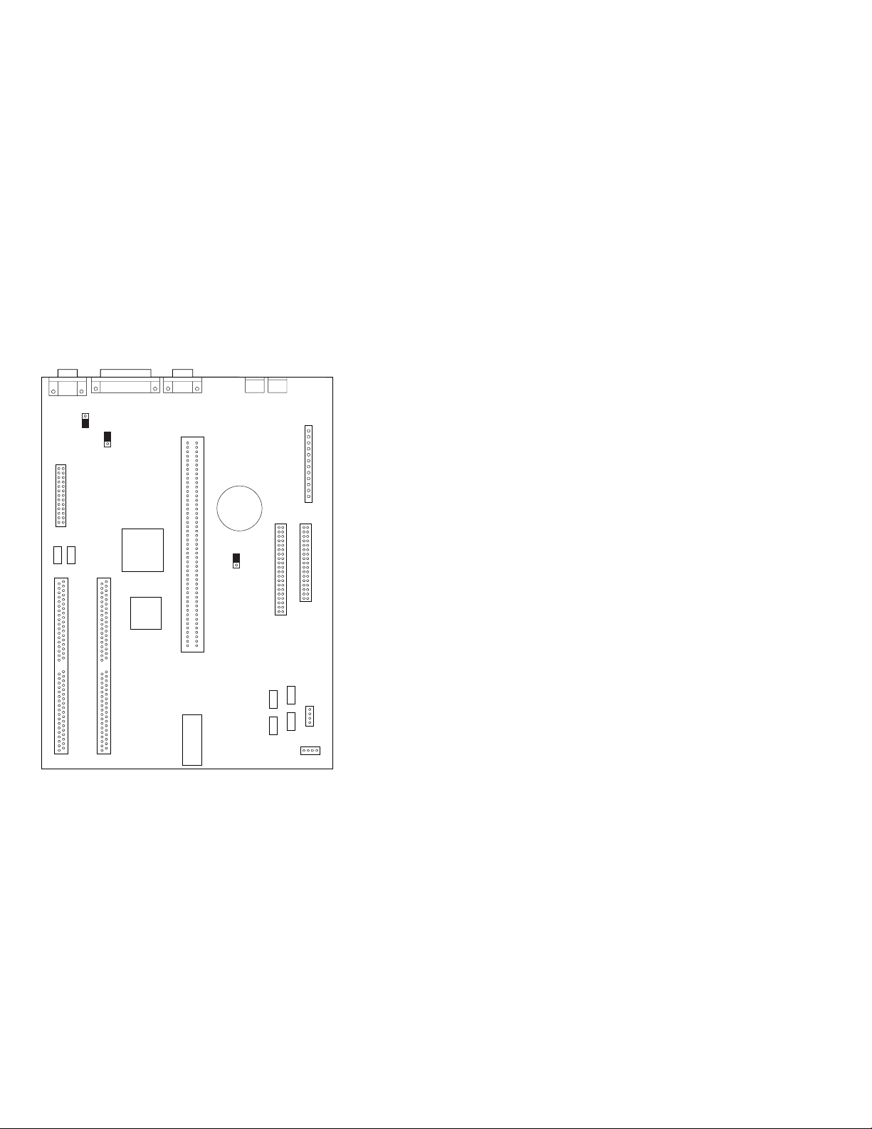
6384 325T System Board
J5 J7 J9 J10J4
J17
J16
21
161
1
J15
J3
25
26
U33 U32
1122
J1 J2
71 717272
Figure 7. 6384 325T
U23
U24
60 120
J6
U20
B1
1
3J8J11
14
39 40
U5
U8
U6
U9
12
112 2
J14
3433
4
J13
1
J12
84 PS/ValuePoint HMM

6384 325T System Board
B1 Battery
J1 Memory-Module Socket 1
J2 Memory-Module Socket 0
J3 Video Feature Connector
J4 Video Port
J5 Parallel Port
J6 Riser Connector
J7 Serial Port
J8 Password Bypass
J9 Mouse Port
J10 Keyboard Port
J11 Hard Disk Connector
J12 Beeper Bypass
J13 Pins 1 and 2—Power-On LED
Pins 3 and 4—Hard Disk LED
J14 Diskette Connector
J15 Power Connector
J16 IRQ9
J17 VGA Enable
U5 512K X 9 System Memory
U6 512K X 9 System Memory
U8 512K X 9 System Memory
U9 512K X 9 System Memory
U20 BIOS
U23 Math Coprocessor
U24 386SLC Processor
U32 256K X 16 Video Memory
U33 256K X 16 Video Memory
Hardware Maintenance Reference 85

6384 425SX System Board
J7 J4J5J16
12
J15
2526
J46
J45
J48
J52
J51
J50
J49
J47
1
5
J11
Figure 8. 6384 425SX
JP17
JP26
JP10
U215
Comm AComm B
161
60 120
J12
JP21JP22
1
1
BT1
J2
JP8
3
4
1
J3
JP24
C17
JP1
U214
12
J8
1221
33 34
4039
J6
86 PS/ValuePoint HMM

6384 425SX System Board
BT1 Battery
C17 Capacitor (Used with JP8 to erase password.)
J2 External Battery
J3 Power Connector
J4 Serial Port (Comm A)
J5 Serial Port (Comm B)
J6 Diskette Connector
J7 Parallel Port
J8 Hard Disk Connector
J11 Hard Disk LED (pin 4 and 5)
J12 Riser Connector
J15 Video Feature Connector
J16 Video Port
J45 Memory-Module Socket Bank 0, 0
J46 Memory-Module Socket Bank 0, 1
J47 Memory-Module Socket Bank 0, 2
J48 Memory-Module Socket Bank 0, 3
J49 Memory-Module Socket Bank 1, 0
J50 Memory-Module Socket Bank 1, 1
J51 Memory-Module Socket Bank 1, 2
J52 Memory-Module Socket Bank 1, 3
JP1 IRQ9
JP8 Battery Select
JP10 VGA Enable
JP17 VGA Enable
JP21 Keyboard Port
JP22 Mouse Port
JP24 Mouse Enable
JP26 Beeper Enable
U214 487SX or 486DX2
U215 486SX Processor
Power-On LED (pin 1 and 2)
Hardware Maintenance Reference 87

6384 433DX or 466DX2 System Board
J9
J7 J4J5J16
161
JP305
JP10
JP17
JP4
12
J15
2526
J10
Comm AComm B
J12
JP209
BT1
1
C17
12
J8
1221
1
JP8
3
1
4
J3
J6
J2
JP207 JP 200 JP201
J52
J51
J50
J49
J48
1
J47
JP206
J46
J45
5
J11
60 120
JP20
Figure 9. 6384 433DX or 466DX2
U300
33 34
4039
U300
88 PS/ValuePoint HMM

6384 433DX or 466DX2 System Board
BT1 Battery
C17 Capacitor (Used with JP8 to erase password.)
J2 External Battery
J3 Power Connector
J4 Serial Port (Comm A)
J5 Serial Port (Comm B)
J6 Diskette Connector
J7 Parallel Port
J8 Hard Disk Connector
J9 Keyboard Connector
J10 Mouse Port
J11 Hard Disk LED (pin 4 and 5)
J12 Riser Connector
J15 Video Feature Connector
J16 Video Port
J45 Memory-Module Socket Bank 0, 0
J46 Memory-Module Socket Bank 0, 1
J47 Memory-Module Socket Bank 0, 2
J48 Memory-Module Socket Bank 0, 3
J49 Memory-Module Socket Bank 1, 0
J50 Memory-Module Socket Bank 1, 1
J51 Memory-Module Socket Bank 1, 2
J52 Memory-Module Socket Bank 1, 3
JP4 BIOS Select
JP8 Battery Select
JP10 VGA Enable
JP17 VGA Enable
JP20 Beeper Enable
JP200 Cache Configuration
JP201 Cache Configuration
JP206 Cache Configuration
JP207 Cache Configuration
JP209 Mouse Enable
JP305 IRQ9
U300 486DX or 486DX2 Processor
Note: Jumpers should be set as shown.
Power-On LED (pin 1 and 2)
Hardware Maintenance Reference 89

6384 /D System Board (Type 1)
(425SX, 433SX, 433DX, or 466DX2)
J14 J7J12J15
161
J8
J13
J4
BT1
1
J1
J47J48
J26
J18
J21J20J19
J25
J16
J17
J24 J23
Figure 10. 6384 /D (Type 1)
60 120
U25
J10 J11
J9
U13
12
J5
21
J3
J2
4039
33 34
J6
U9
U10
90 PS/ValuePoint HMM

6384 /D System Board (Type 1)
(425SX, 433SX, 433DX, or 466DX2)
BT1 Battery
J1 Power Connector
J2 Diskette Connector
J3 Hard Disk Connector
J4 Keyboard Connector
J5 BootBlock (not used: do not change)
J6 Write Disable
J7 Serial Port (Comm A)
J8 Mouse Port
J9 Password Bypass
J10 Processor Upgrade
J11 Processor Upgrade
J12 Serial Port (Comm B)
J13 Riser Connector
J14 Parallel Port
J15 Video Port
J16 Monochrome Adapter
J17 System Board Video Enable
J18 Memory-Module Socket, MEM 1
J19 Memory-Module Socket, MEM 2
J20 Memory-Module Socket, MEM 3
J21 Memory-Module Socket, MEM 4
J23 Power-On LED
J24 Hard Disk LED
J25 Speaker
J26 Video Feature Connector
J47 Video Memory Connector
J48 Video Memory Connector
U9 486SX Processor
U10 486DX or 486DX2 Processor Upgrade Socket
U13 Cache Socket
U25 Riser Connector Extension
Note: Jumpers should be set as shown.
Hardware Maintenance Reference 91

6384 /D System Board (Type 2)
(425SX, 433SX, 433DX, or 466DX2)
J6
J5
J4
61
1
J11
J2
J3
J1
BT1
1
J8
VEM1
J14
J22 J21 J20 J19
VEM2
J13
Figure 11. 6384 /D (Type 2)
J12
60 120
J26
J25
U49
U56
J24
J15
J17
J18
J10
J16
2
1
21
J9
J7
4039
3334
U53
U58
92 PS/ValuePoint HMM
 Loading...