


Intel PM945GC-478 Mainboard
User’s Manual
Rev: EG1.0
Date: 2008.1

CONTENTS
CHAPTER 1 INTRODUCTION·······································2
1.1 Chipset Introduction············································2
1.2 Specification··················································2
1.3 Mainboard Introduction·········································2
CHAPTER 2 PACKAGE CONTENTS··································3
CHAPTER 3 MAINBOARD LOCATIONS······························4
CHAPTER 4 INSTALLATIONS·······································5
4.1 Jumper Setting and Slot···········································5
CHAPTER 5 BIOS SETUP···········································6
5.1 Main menu·····················································7
5.2 Standard CMOS Features·········································8
5.3 Advanced BIOS Features·········································9
5.4 Advanced Chipset Features·······································10
5.5 Integrated Peripherals···········································11
5.6 Power Management Setup········································13
5.7 Set Supervisor Password & Set User Password·······················14
5.8 Save Exit & Without Save Exit Setup·······························14
1

Chapter 1 Introduction
1.1 Chipset Introduction
Intel 945GC Chipset
The Intel 945GC chipset supports the latest PC technologies such as Socket 478
CPU, dual-channel DDRII memory architecture and PCI Express x16 graphics
card interface. Intel Graphics Media Accelerator 950 provides a significant
increase in graphics performance. 6 high-speed USB 2.0 ports.
Dual-channel DDRII
This Intel 945GC chipset motherboard supports TWO DDRII DIMM interfaces
that can make you have more use room. Dual-channel can give you the fastest
frequency.
1.2 Specification
INTEL 945GC
·Intel 945GC + ICH6;
·Supports Socket 478 CPU
·Supports 533/800 MHz HOST BUS Frequency;
·Intel Graphics Media Accelerator 950 VGA;
·Dual channel Mode DDRII 400/533MHz;
·Supports 1 PCI Express x16 Slot;
·Supports 2 PCI Slots;
·Supports 6 channel sound input;
·Supports 6 USB2.0 ports;
1.3 Mainboard Introduction
Key Features:
-Chipset:
Intel 945GC + ICH6
-CPU:
Supports Intel Socket 478 CPU
- Supports 533/800MHz HOST BUS Frequency
-Memory:
Supports DDRII 400/533MHz Memory
2

-Built-in Powerful Integrated Graphics
Integrated display function technologies without extend VGA card
Integrated 2D/3D Graphics Controller
-Provides one channel connecting two IDE drives
Supports Ultra ATA66/100/133synchronous DMA modes
-Provides 2 channel connecting 2 SATA drives with speed up to 150MB/S
-I/O:
1 floppy port support format 360K/720K/1.2M/1.44M/2.88M disk
1 serial port
1 parallel port supports EPP/ECP/SPP transfers
6 USB2.0 ports
1 PS/2 port
2 SATA ports
1 10/100M Network Adapter
-Onboard AC’97 2.3 specification compliant
Supports six channel sound input (example Realtek ALC653)
-Expansion slot:
One PCIE_X16 slot
Two 32-bit PCI slots 2.2 specification compliant
-Dimension
MICROATX
Chapter 2 Package Contents
Your mainboard package contains the following items:
1 x Intel 945GC mainboard
1 x 40-pin Ultra DMA 66/100/133 IDE ribbon cable
1 x SATA cable
1 x Driver installed CD
1 x 0ne user’s manual
1 x bracket
3
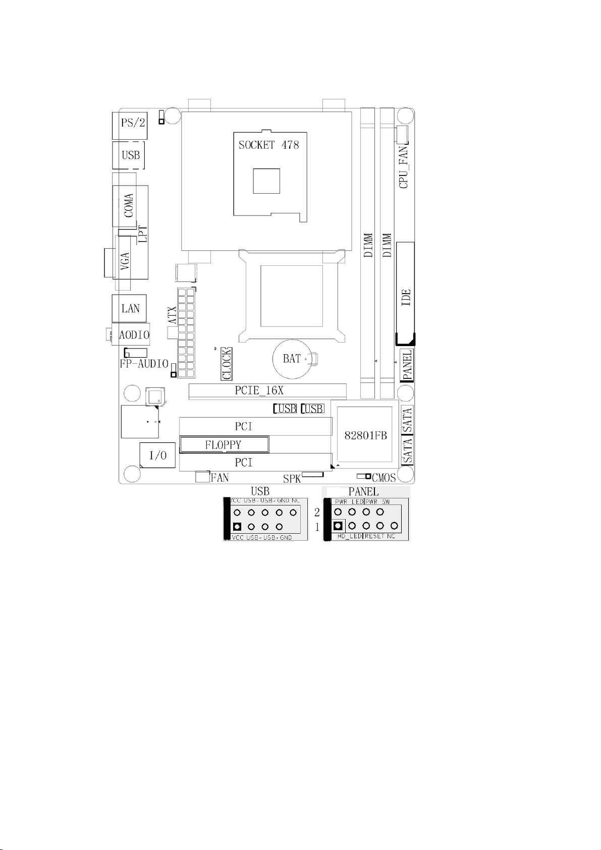
Chapter 3 Mainboard Locations
82945GC
4

Chapter 4 Installations
4.1 Jumper Setting and Slot
Clear CMOS Jumper setting
1-2 (Default) Normal
2-3 Clear CMOS
Audio: Front panel Jumper setting
PIN Function PIN Function
1 MIC+ 2 Ground
3 Vbias 4 AuD_Vcc(AVCC)
5 AuD_R_Out 6 R_Out Back
7 N.C. 8 Key
9 AuD_L_Out 10 L_Out Back
SATA: PIN Jumper setting
PIN SATA1 Function PIN SATA2 Function
1 Ground 1 Ground
2 RSATA_RXP1 2 RSATA_RXP2
3 RSATA_RXN1 3 RSATA_RXN2
4 Ground 4 Ground
5 RSATA_TXN1 5 RSATA_TXN2
6 RSATA_TXP1 6 RSATA_TXP2
7 Ground 7 Ground
Expansion slot
DIMM1/DIMM2 240 PIN DDRII MEMORY SLOT
PCI1/PCI2 120 PIN PCI BUS expansion slots
PCIE_X16 Intel PCI Express X16 expansion slots
USB: Expansion Connector
PIN Function PIN Function
1 VCC: Power 2 VCC: Power
3 D-:Data- Signal 4 D-: Data- Signal
5 D+: Data- Signal 6 D+: Data- Signal
7 GND: Ground 8 GND: Ground
9 KEY 10 NC
5

Connectors
PS/2(Bottom) PS/2 Keyboard(Purple)
PS/2(TOP) PS/2 Mouse Header(Green)
R_USB1 USB1/2 Connector Port
F_USB2 USB3/4 Connector Port
F_USB3 USB5/6 Connector Port
LPT Printer Connector Port
COM1 Serial Port COM1 Connector port
VGA On-board VGA connector
LINE OUT/
Audio Output/Audio Input/Microphone
LINE IN/MIC
IDE Primary/Secondary IDE port
SATA1/SATA2 SATA Port
FDD Floppy Disk Drive Connector Port
ATX/ATX_12V Power Supply Connector
ATX/ATX_12V
port
CPU_FAN/PWR_FAN CPU/System FAN Port
Function Port Panel
Pin2: Power Supply Anode;
Power Supply LED
Pin4: Ground
HHD LED
Pin1: Power supply Anode
Pin3: LED Signal
Power Supply Switch
Reset Switch
Pin6、8:Switch Signal
Pin5、7:Reset Switch
Chapter 5 BIOS Setup
The BIOS setup Utility record settings and information of your computer,
such as date and time, the type of hardware installed, and various configuration
settings. Your computer applies those information to initialize all the
components when booting up and basic function of coordination between system
components.
If the Setup Utility configuration is incorrect, it may cause the system to
malfunction. It can even stop you computer booting properly. If it happens, you
can use the clear CMOS jumper to clear the CMOS memory which has stored
the configuration information; or you can hold down the Page
Up Key while rebooting your computer. Holding down the Page Up key also
clears the setup information.
6

5.1 Main menu
You can use cursor arrow keys to highlight anyone of options on the main menu
page. Press Enter to select the highlighted option. Press the Escape key to leave
the setup utility. Press the F9 key to go back to menu in BIOS. Some options on
the main menu page lead to tables of items with installed value that you can use
cursor arrow keys to highlight on item, and press page
Up and page Down keys to cycle through alternative values of that item. The
other options on the main menu page lead to dialog boxes that require your
answer Yes or No by hitting the Y or N keys. If you have already changed the
setup utility, press F10 to save those changes and exit the utility.
Standard CMOS Features
Setup date、time、floppy type
Advanced BIOS Features
Setup BIOS provides function, for example virus、boot-strap induct
Advanced Chipset Features
Setup mainboard chipset parameter, for example DRAM Timing
Integrated Peripherals
Setup include mainboard all peripherals drive
Power Management Setup
Setup CPU、Hard disk、Monitor drive power save mode
PnP/PCI Configurations
Setup PnP and PCI interface parameter
PC Health Status
Frequency/Voltage Control
Load Fail-Safe Defaults
Setup the default values in system
Load Optimized Defaults
7

Setup the best performance values in system
Set Supervisor Password
Setup supervisor password in system
Set User Password
Setup user password in system
Save & Exit Setup
Setup save and exit, press Y to save and exit
Exit Without Save Setup
Exit without Save and exit, press N to without save and exit
5.2 Standard CMOS Features
Date(mm:dd:yyyy)
These items set up system date
Time(hh:mm:ss)
These items set up system time
Primary/Secondary Master/Slave
These items configure devices connected to the Primary and Secondary IDE
channels. To configure an IDE hard disk drive, Choose Auto. If the Auto
setting fails to find a hard disk drive, set it to User , and then fill in
the hard disk characteristics manually. If you have a CD-ROM drive, select
the setting CD-ROM. If you have an ATAPI device with removable media,
select Floptical.
Drive A/B
Video
Halt on
Base Memory
Expanded Memory
8

Tot al Me mo ry
5.3 Advanced BIOS Features
CPU Feature Default: Press Enter
Delay Prior to Thermal Default: 16Min
Thermal Management Default: Thermal Monitor1
Limit CPUID MaxVal Default: Disabled
C1E Function Default: Auto
Execute Disable Bit Default: Enabled
Removable Device Priority Default: Press Enter
Floppy Disks
Hard Disk Boot Priority Default: Press Enter
Virus Warning Default: Disabled
CPU L1&L2 Cache Default: Enabled
Leave these items enabled since all the processors that can be installed on
this board have internal L2 cache memory.
Hyper–Threading Technology Default: Enabled
Quick Power On Self Test Default: Enabled
USB Flash Disk Type Default: Floppy
First Boot Device Default: Removable
When system boot-strap first time detect device.
Second Boot Device Default: CDROM
When system boot-strap first time detect device.
Third Boot Device Default: Hard Disk
When system boot-strap first time detect device.
Boot Other Device Default: Enabled
If you enable this item, the system will also search for other boot devices if it
fails an operating system from the first two locations.
Swap Floppy Drive Default: Disabled
If you have two diskette drives installed and you enable this item, drive A
9
becomes drive B and drive B becomes drive A.
Boot Up Floppy Seek Default: Enabled
Boot Up NumLock Status Default: On
Gate A20 Option Default: Normal
Typematic Rate Setting Default: Disabled
Typematic Rate (chars/sec) Default: 6
Typematic Delay (Msec) Default: 250
Security Option Default: Setup
ACPI Mode Default: Enabled
MPS Version Control For OS Default: 1.4
OS Select For DRAM>64MB Default: NON-OS2
Report No FDD For WIN 95 Default: No
Full screen Logo show Default: Enabled
Small Logo (EPA) show Default: Enabled
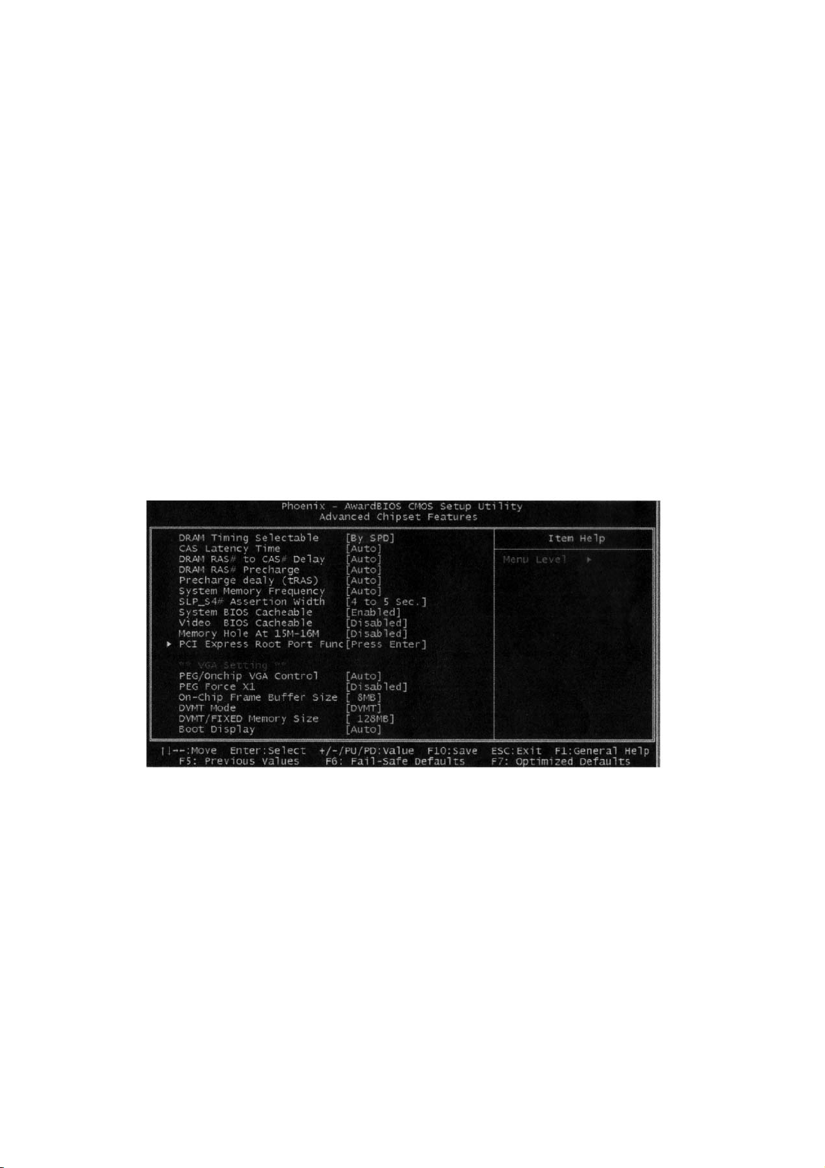
5.4 Advanced Chipset Features
DRAM Timing Selectable Default: By SPD
X CAS Latency Time Default: Auto
X DRAM RAS# to CAS# Delay Default: Auto
X DRAM RAS# Precharge Default: Auto
X Precharge dealy (tRAS) Default: Auto
X System Memory Frequency Default: Auto
SLP-S4# Assertion Width Default: 4 to 5 sec
System BIOS Cacheable Default: Enabled
Video BIOS Cacheable Default: Disabled
Memory Hole At 15M-16M Default: Disabled
PCI Express port 1 Default: Auto
PCI Express port 2 Default: Auto
10

PCI Express port 3 Default: Auto
PCI Express port 4 Default: Auto
PCI Express port 5 Default: Auto
PCI Express port 6 Default: Auto
PCI-E Compliancy Mose Default: vl.oa
**VGA Setting**
PEG/Onchip VGA Contro1 Default: Auto
On-chip Frame Buffer Size Default: 8MB
DVMT Mode Default: DVMT
FIXED Memory Size Default: 128MB
DVMT Memory Size Default: 128MB
Boot Display Default: Auto
5. 5 Integrated Peripherals
OnChip IDE Device Default: Press Enter
IDE HDD Block Mode Default: Enabled
IDE DMA Transfer access Default: Enabled
On-Chip Primary/ Secondary PCI IDE Default: Enabled
Chipset inside the first/second channel of PCI IDE interface
IDE Primary/ Secondary Master/Slave PIO Default: Auto
The first/second IDE Primary Master/ Primary slave control PIO mode
IDE Primary/ Secondary Master/Slave UDMA Default: Auto
***On-Chip Serial ATA Setting***
X SATA Mode Default: IDE
On-Chip Serial ATA Default: Auto
X SATA PORT Speed Settings Default: Disabled
PATA IDE Mode Default: Primary
SATA Port Default: pl,p3 IS Secondary
11

Onboard Device Default: Press Enter
USB Controller Default: Enabled
USB 2.0 Controller Default: Enabled
USB Keyboard Support Default: Disabled
USB Mouse Support Default: Disabled
Azalia/AC97 Audio select Default: Auto
Onboard LAN controller Default: Enabled
BIOS ROM Write Protect Default: Enabled
Onboard Lan PXE ROM Default: Enabled
Super IO Device Default: Press Enter
KBC input clock Default: 8 MHz
POWER ON Function Default: BUTTON ONLY
X KB Power ON Password Default: Enter
X Hot Key Power ON Default: Ctrl-F1
Onboard FDC Controller Default: Enabled
Setup onboard FDC controller
Onboard Serial port1/2 Default: 3F8/IRQ4; 2F8/IRQ4
Setup onboard serial port1/2
UART Mode Select Default: Normal
12
Setup UART mode select
UR2 Duplex Mode Default: Half
Onboard Parallel port Default: 378/IRQ7
Setup select parallel port
Parallel Port Mode Default: SPP
Setup parallel port mode
ECP Mode USE DMA Default: 3
PWRON After PWR=Fail Default: off
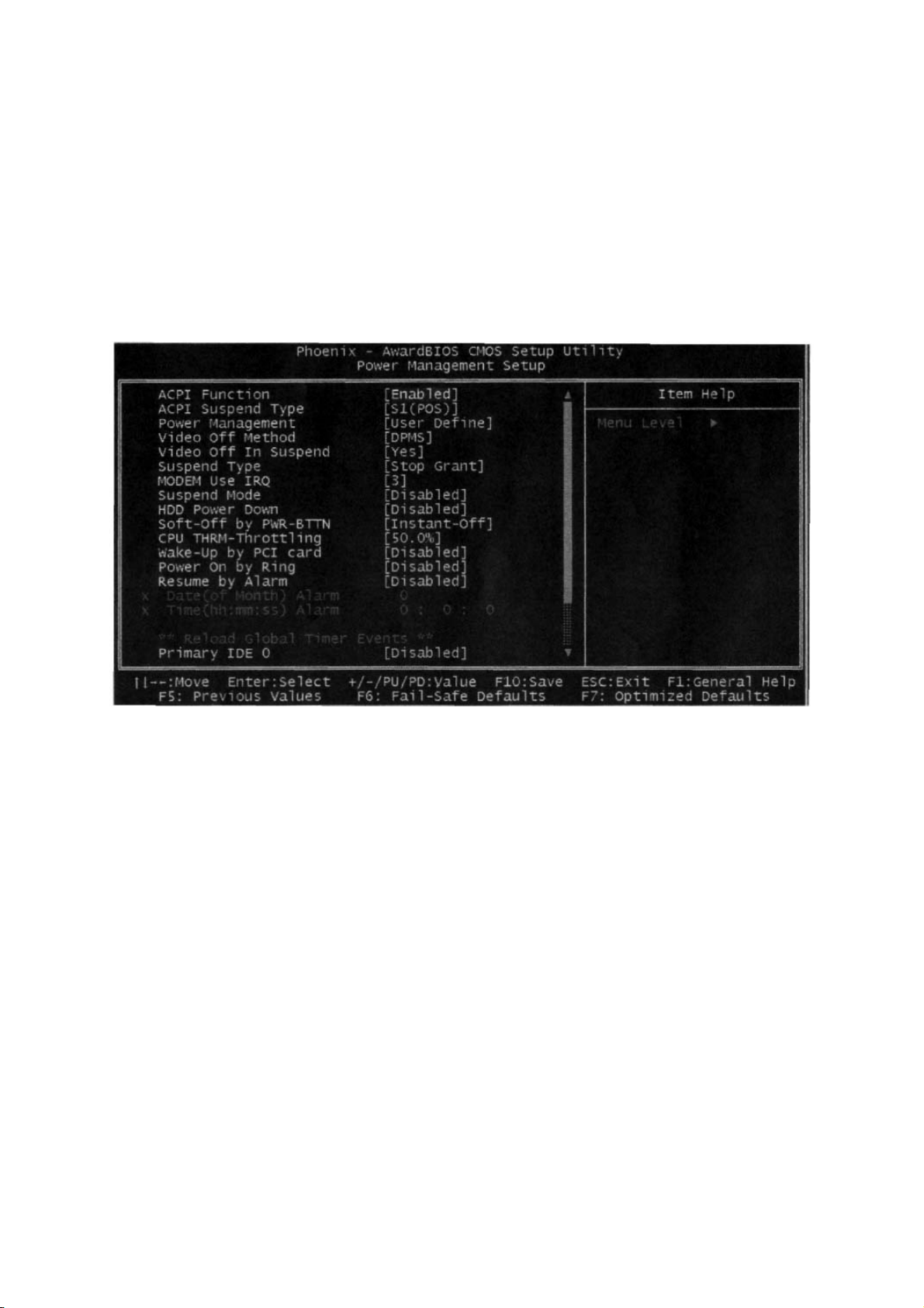
5.6 Power Management Setup
ACPI Function Default: Enabled
Setup if use ACPI function
ACPI Suspend Type Default: S1 (POS)
Power Management Default: User Define
Video off Method Default: DPMS
Video off In Suspend Default: Yes
Suspend Type Default: Stop Grant
MODEM Use IRQ Default: 3
Suspend Mode Default: Disabled
HDD Power Down Default: Disabled
Soft-Off by PWR-BTTN Default: Instant-Off
Wake-up by PCI card Default: Disabled
Power On by Ring Default: Disabled
Resume by Alarm Default: Disabled
Date (of Month) Alarm Default: 0
Time (hh:mm:ss) Alarm Default: 0
** Reload Global Timer Events **
Primary/Secondary IDE 0/1 Default: Disabled
13

FDD,COM,LPT Port Default: Disabled
PCI PIRQ[A-D]# Default: Disabled
5.7 Set Supervisor Password & Set User Password
If you highlight this item and press Enter, a dialog box appears that you can
enter a supervisor password. You can enter no more than six letters or
numbers. Press Enter after you have typed in the password. There will be the
second dialog box asking you to retype the password for confirmation. Press
Enter after you have retyped it correctly. Then the password is required for
the access to the setup utility or for it at start-up ,depending on the setting of
the password check item in advanced setup.
5.8 Save Exit & Without Save Exit Setup
Highlight this item and press Enter to save the changes that you have made in
the setup utility configuration and exit the program. When the save and exit
dialog box appears. Press Y to save and exit; or press N to exit without saving.
14
 Loading...