

Page 1

EX-98211
Fanless Intel Celeron/Pentium M
Box PC
Quick Installation Guide
Version 1.0
Page 2

Chapter1 1 General Information
1.1 Introduction
The EX-98211 Box PC is targeted at many different application fields. By adopting it, you can pinpoint
specific markets, such as Thin Client, KIOSK, information booth, GSM Server, environment-critical and
space-critical applications.
All-In-One Platform
The CPU, DRAM and even software are integrated to provide a plugand- play machine.
Compact-sized
The kernel of EX-98211 is EX-90212, which is a non-standard form factor embedded board. The whole
system consumes only a few space.
Fanless and Modular CPU Board
By using a low power processor, the system does not have to rely on fans, which are often unreliable, and
cause dust to circulate inside the equipment. The modular design facilitates maintenance or possible
upgrades on the CPU board. Modular Box PC can be easily modified to fit many different applications
according to customers' requests.
Powerful Communication Capability
The EX-98211 provides serial ports, parallel port, Ethernet, USB, Mini Card slot, LPT, DVI and Digital
I/O expansion slot.
CRT SVGA
EX-98211 supports super 2D video performance and consumes minimal power.
Advanced storage solution
EX-98211 comes with Compact Flash, which offers a better, faster and more cost-effective
expansibilities for various applications.
Trustworthy
The onboard Watchdog Timer can invoke an NMI or system RESET when your application loses control
over the system.
Windows OS Support:
offers platform support for Windows CE 5.0, Windows CE 6.0, Windows XP, Windows XPe, Linux .
The optional Windows CE operating system specifically for the EX-98211 is available for Windows CE
application program builders.
Page 3
1.2 Packing List
After opening the package, carefully inspect the contents. If any of items is missing or
appears damaged, please contact with your local dealer or distributor. The package
should contain the following items:
1 x EX-98211 Box PC
2 x EPE FOAM
1 x Accessory Box (CD/Quick Installation Guide/Screw/Cable)
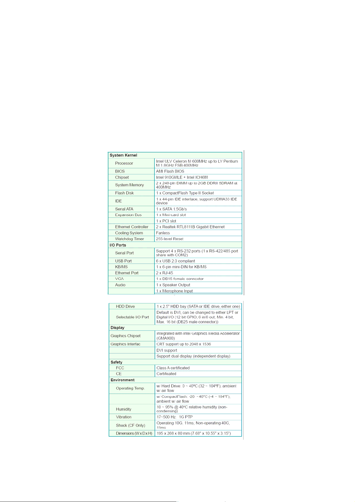
1.3 System
Page 4
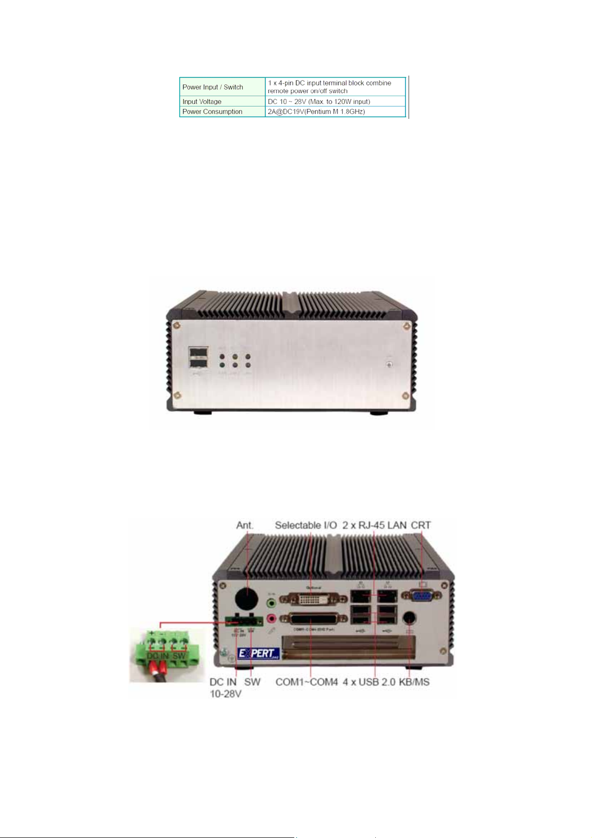
1.4 Power Information
1.5 I/O Ports Arrangement
The EX-98211 has 4 serial ports, 6 USB (Host) ports, and 2 RJ-45 LAN ports. The
arrangement of these ports is shown in Figure 1.1 & Figure 1.2
1.5.1 Front View
1.5.2 Back View
Figure 1.1: Front View of EX-98211
Figure 1.2: Back View of EX-98211
Page 5
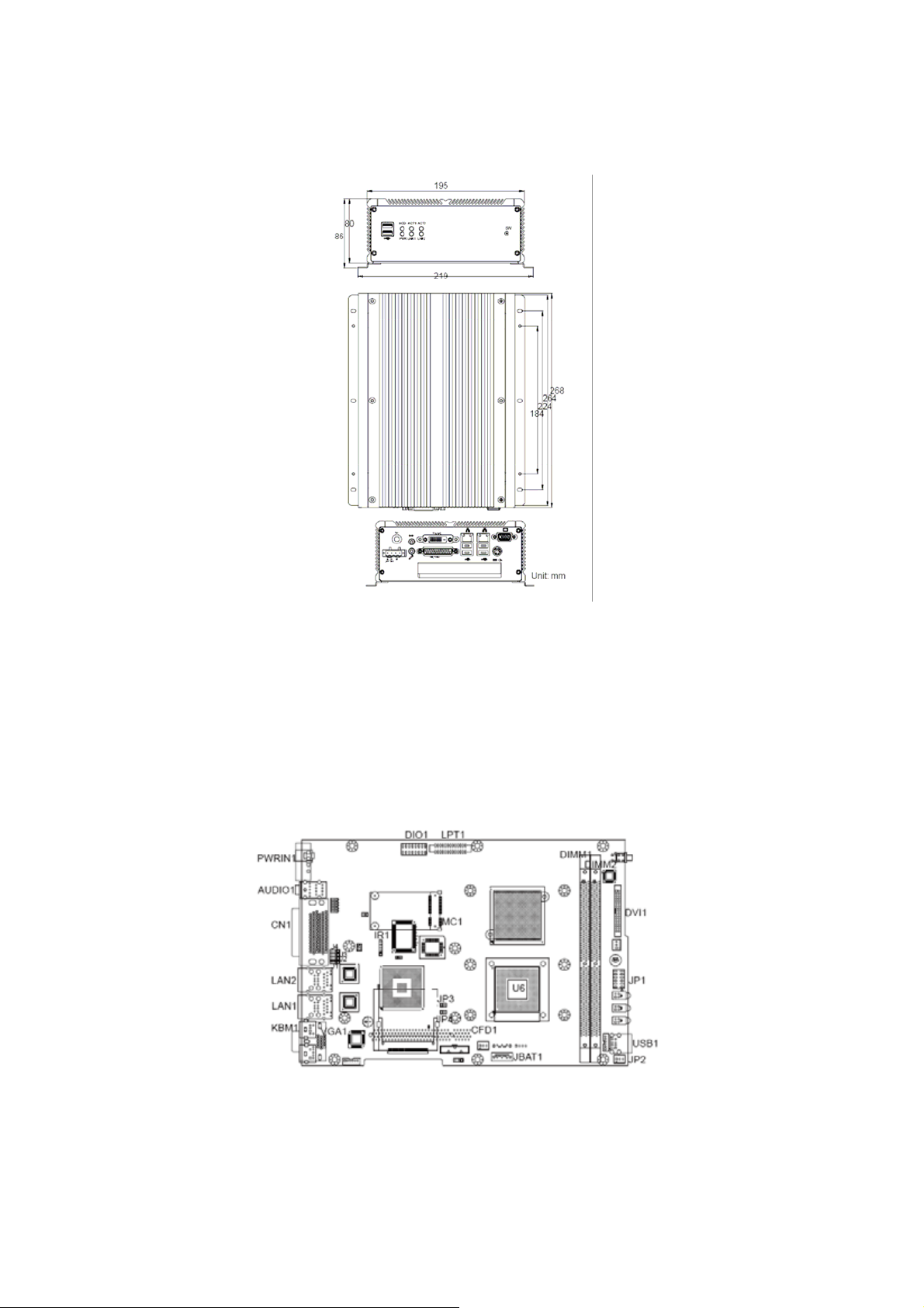
1.6 Dimensions
‧ Dimension (W x H x D): 195 x 268 x 80 mm (7.68" x 10.55" x 3.15")
Figure 1.3: Dimensions
Chapter2 The Engine of EX-98211
2.1 Introduction
The engine of EX-98211 is constructed by the combination of one PCBA board. Such a combination
makes system customization feasible.
Figure 2.1: EX-98211 Main Board Top View
Page 6
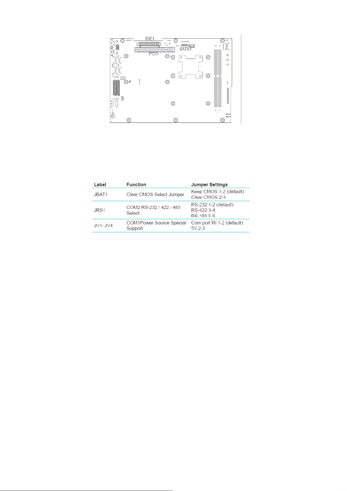
Figure 2.2: EX-98211 Main Board Bottom View
2.2 Jumpers and Connectors
EX-98211 Main Board Jumper Setting
Page 7

EX-98211 Main Board Connector Setting
Page 8

JRS1 RS-232/422/485 Selection
JP1 LAN LED Connector
Page 9

IDE1: Primary IDE Connector
Connector type: One onboard 44-pin box headers, primary IDE
Page 10

CFD1: Compact Flash Disk (Share IDE1)
Connector type: 50-pin compact flash type I/II
LPT1: Parallel Port Connector
Connector type: D-Sub 25-pin female.
SATA1~2: S-ATA1 Connector
Page 11

LAN1/LAN2 Connector (USB Port 1, 2 ~ USB Port 3, 4)
Connector: This connector supports USB 2.0 x 4.
Type: USB 2.0 x 4
USB1 Connector (USB Port 5, 6)
VGA1: CRT Connector
Connector type: D-Sub 15-pin female.
DVI1: DVI Connector
Page 12

CN1: (COM1~4 +GPIO 2 In/2 Out Option RS422/485 output)
IR1: Infrared (IR) Connector
KBM1: PS/2 Keyboard & Mouse
Connector type: external 6-pin Mini DIN connector on bracket
AUDIO1: Audio Interface Port
PWRIN1: DC Adapter Power Input
Page 13

RS-422/485, GPIO Function Jumper
Chapter 3 Maintenance
Hardware Installation
The EX-98211 is designed to be modular, slim and lightweight for easier
maintenance. The following section describes simple hardware installations.
3.1 Remove Top Cover
1. Locate 6 screws which secure the top cover.
2. Use screw driver to remove the top cover screws. Keep the screws safelyfor later use.
3. Pull the top cover slightly upward.
3.2 Installing CPU
1. Locate 6 screws which secure the Thermal Lump.
2. Use screw driver to remove the 6 screws. Keep the screws safely for later
use.
Page 14

3. The processor socket comes with a screw to secure the CPU. As showing
in the picture bellow, loose the screw first before inserting the CPU.
4. Place the CPU into the socket by making sure the notch on the corner
of the CPU corresponding with the notch on the inside of the socket. Once
the CPU has slid into the socket, lock the screw.
5. The contact area and gap between the processor and the heatsink
require a thermal pad or thermal paste. Make sure that heatsink of the
CPU top surface is in complete contact to avoid the CPU overheating
problem. If not, it would cause your system or CPU to be hanged,
unstable, or damaged.
Page 15

3.3 Installing Memory Module
1. Locate the 240-pin LONG DIMM sockets.
2. Align the LONG DIMM on the socket and let the notch on the LONG DIMM meet the break on socket.
3. Firmly insert the LONG DIMM into the socket.
3.4 Installing CF Card
1. Locate 2 screws which secure the Thermal Lump of South Bridge.
2. Use screw driver to remove the 2 screws. Keep the screws safely for later
use.
Page 16

3. Remove the Thermal Lump of South Bridge.
4. To install a Compact Flash Memory Card into the Main Board, align the
notch on the card with the Compact Flash socket in the Main Board. Then
firmly insert the card into the socket until it is completely seated.
3.5 Remove Bottom Cover
1. Unscrew 6 screws which secure the bottom cover.
2. Use screw driver to remove the bottom cover screws. Keep the screws
safely for later use.
Page 17

3.6 Installing Hard Disk Drive
1. Upside down the Box PC. Remove the Bottom Cover.
2. Locate the 4 screws on the HDD Holder Bracket.
3. Use screw drvier to remove the screws. Keep the screws safely for later
use.
4. Put the HDD into the HDD Holder Bracket and screw it on.
Page 18

5. Connect the SATA cable between the HDD and the Main Board.
3.7 Installing Riser Card
1. Insert PCI card into the PCI slot.
2. Locate the screw on the slot bracket.
3. Use screw driver to remove the screw. Keep the screw safely for later use.
Page 19

3.8 Installing Wall-mount Bracket
1. Upside down the Box PC. Please locate the 8 screw holes on the bottom
cover.
2. Match the screws on the wall-mount kit and screws onto the main unit.
 Loading...