

Page 1
Boxed Intel® Pentium® II Xeon™ Processor Installation Notes
Failure to properly install and integrate the processor may void your
warranty coverage.
Integration Issues and Information
Before you install the processor(s) into a system, integration issues need to be considered. See document number 24544, “Integration Notes for the boxed Intel® Pentium® II
Xeon™ Processor” on the World Wide Web at: http://support.intel.com.
Ensure proper cooling and adequate airflow for the processor(s) by referring to document number 24545 “Thermal Management Notes for the Intel Pentium II Xeon
processor” on the World Wide Web at http://support.intel.com.
Intel Pentium II Xeon processor specifications can be found on the on the World Wide
Web at http://developer.intel.com. Refer to the “Intel Pentium II Xeon Processor
Datasheet” Order number 2437701.
Install the retention mechanism(s) onto the motherboard using the motherboard
manufacturer’s instructions. The illustrations shown in this manual correspond with
the retention mechanisms that are supplied with the boxed Intel MS440GX workstation motherboard.
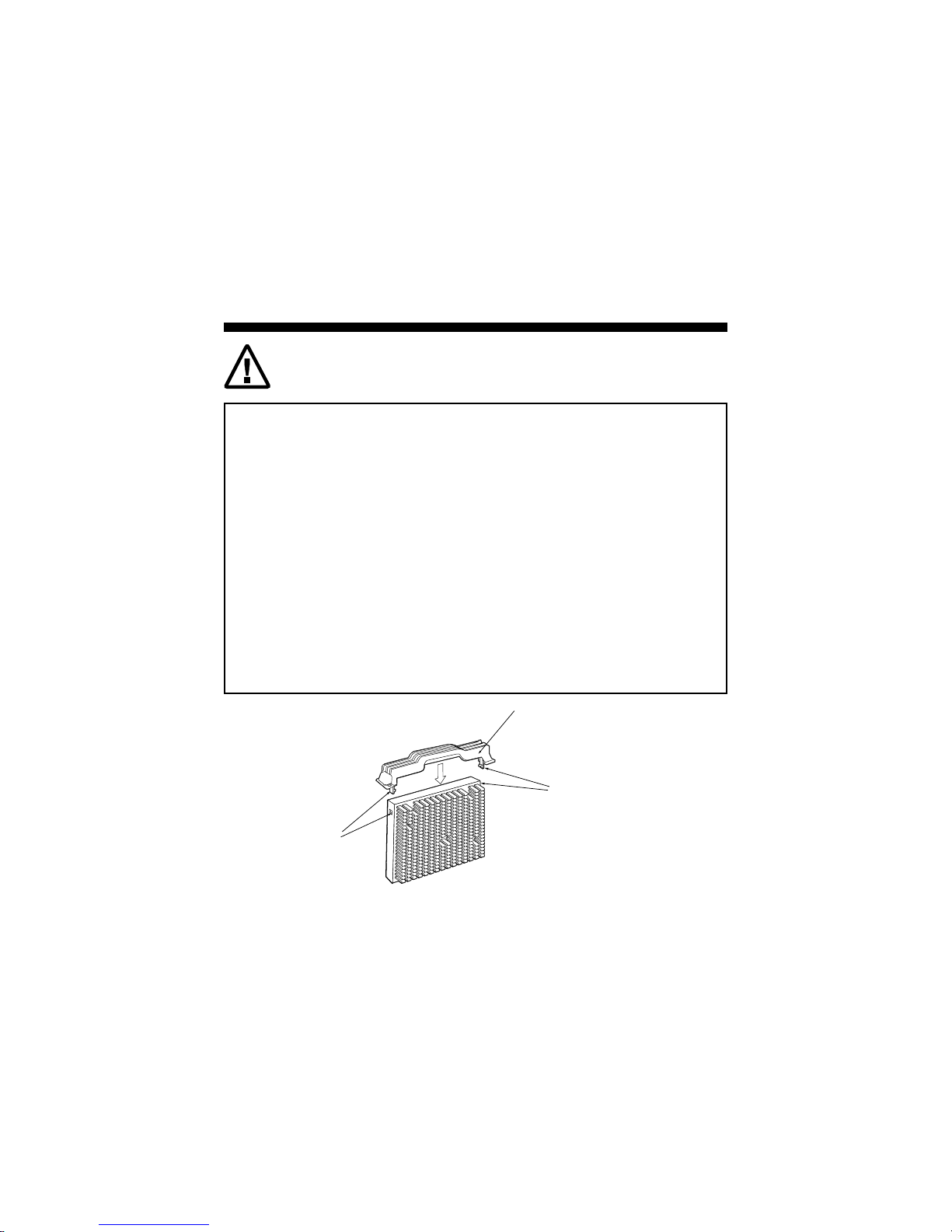
D
Attach the Dual Retention Mechanism (DRM) top (D) to the processor by snapping the
clips (H1, H2) into the two recesses on the sides of the processor.
H1
H2
OM08281
1
Page 2
C
C
A
B
D
E
DIMM Slots
E
OM08285X
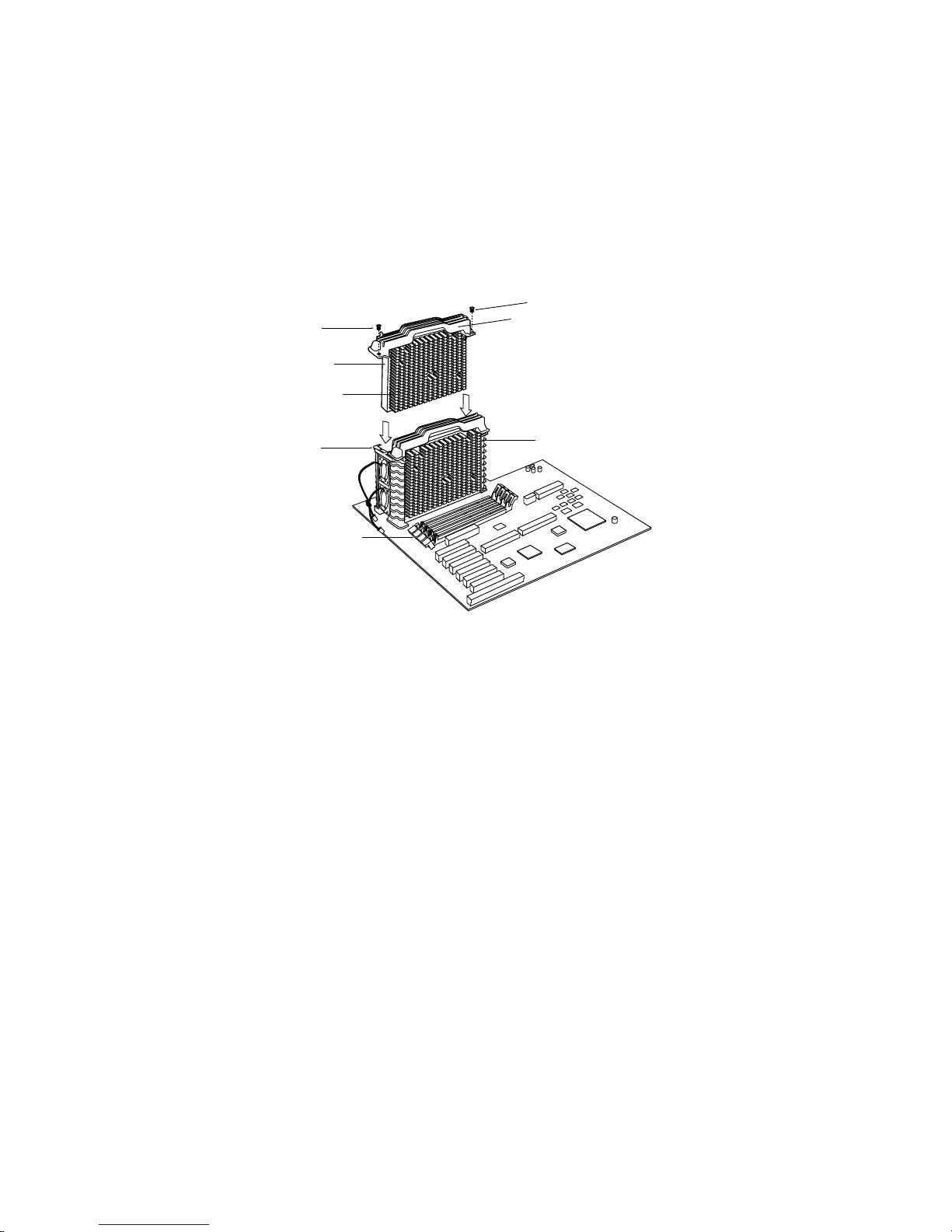
Orient the processor (A) so that the heatsink (B) faces the DIMM slots. Slide the
processor into the retention mechanism (E) ensuring that the Dual Retention
Mechanism (DRM) top screw holes align with the retention mechanism screw holes.
Press down firmly until the processor is seated in the processor connector (G). Secure
the DRM top (D) to the retention mechanism (E) using the appropriate screws (C). If
this is a single processor system, install the termination card in the connector labeled P1
(L). Once the termination card is installed in the connector labeled P1 (L), secure the
DRM top (D) to the retention mechanism using the appropriate screws (C).
2
Page 3

C
D
A
B
E
P0 connector
DIMM Slots
P1
connector
L
G
E
OM08284X
To install a second processor, remove any termination card located in the processor
connector labeled P1. Orient the second processor (A) so that the heat sink (B) faces
the DIMM slots. Slide the processor into the processor retention mechanism (E).
Press down firmly until it is seated in the processor connector labeled P1. Secure the
DRM top (D) to the retention mechanism (E) using the appropriate screws (C).
Part Number 724352-001
Second Edition September 1998
3
Page 4

Place the Intel Inside® logo label on the front of the chassis as shown. Please do not
place the label on the monitor, keyboard, disk drive, or other peripheral equipment.
Copyright Ó Intel Corporation 1998. Third-party brands and names are the property of their respective
owners.
Information in this document is provided in connection with Intel products. No license, express or
implied, by estoppel or otherwise, to any intellectual property rights is granted by this document.
Except as provided in Intel's Terms and Conditions of Sale for such products, Intel assumes no
liability whatsoever, and Intel disclaims any express or implied warranty, relating to sale and/or use
of Intel products including liability or warranties relating to fitness for a particular purpose,
merchantability, or infringement of any patent, copyright or other intellectual property right. Intel
products are not intended for use in medical, life saving, or life sustaining applications. Intel may
make changes to specifications and product descriptions at any time, without notice.
Designers must not rely on the absence or characteristics of any features or instructions marked
“reserved" or "undefined." Intel reserves these for future definition and shall have no responsibility
whatsoever for conflicts or incompatibilities arising from future changes to them.
®
The Intel
may cause the product to deviate from published specifications. Current characterized errata are
available on request or on the World Wide Web at http://developer.intel.com.
Pentium® II Xeon™ processor may contain design defects or errors known as errata which
4
 Loading...