

Compact Board PCM - 6892 Rev.B
PCM-6892 Rev.B
Intel® ULV Celeron®
400 / 650 MHz Processor
Compact Board
With LCD, Ethernet, TV-Out,
Mini PCI, Speaker out
PCM-6892 Rev. B Manual 4th Ed.
May 2005

Compact Board PCM - 6892 Rev.B
Copyright Notice
This document is copyrighted, 2005. All rights are reserved. The original
manufacturer reserves the right to make improvements to the products
described in this manual at any time without notice.
No part of this manual may be reproduced, copied, translated, or
transmitted in any form or by any means without the prior written
permission of the original manufacturer. Information provided in this
manual is intended to be accurate and reliable. However, the original
manufacturer assumes no responsibility for its use, or for any infringements upon the rights of third parties that may result from its use.
The material in this document is for product information only and is
subject to change without notice. While reasonable efforts have been
made in the preparation of this document to assure its accuracy,
AAEON assumes no liabilities resulting from errors or omissions in this
document, or from the use of the information contained herein.
AAEON reserves the right to make changes in the product design
without notice to its users.
i

Compact Board PCM - 6892 Rev.B
Acknowledgments
All other products’ name or trademarks are properties of their respective
owners.
l Award is a trademark of Award Software International, Inc.
l CompactFlash™ is a trademark of the Compact Flash Association.
l Intel®, Pentium® and Celeron® are trademarks of Intel® Corporation.
l Microsoft Windows® is a registered trademark of Microsoft Corp.
l ITE is a trademark of Integrated Technology Express, Inc.
l IBM, PC/AT, PS/2, and VGA are trademarks of International Business
Machines Corporation.
l SoundBlaster is a trademark of Creative Labs, Inc.
ii

Compact Board PCM - 6892 Rev.B
Packing List
Before you begin installing your card, please make sure that the
following materials have been shipped:
• 1 PCM-6892 Rev. B CPU Card
• 1 Jumper cap
• 1 Quick Installation Guide
• 1 CD-ROM for manual (in PDF format) and drivers
If any of these items should be missing or damaged, please contact your
distributor or sales representative immediately.
iii

Compact Board PCM - 6892 Rev.B
Contents
Chapter 1 General Information
1.1 Introduction............................................................................ 1-2
1.2 Features................................................................................... 1-4
1.3 Specifications...........................................................................1-5
Chapter 2 Quick Installation Guide
2.1 Safety Precautions...................................................................2-2
2.2 Location of Connectors and Jumpers..................................... 2-3
2.3 Mechanical Drawing............................................................... 2-5
2.4 List of Jumpers........................................................................2-7
2.5 List of Connectors.................................................................. 2-8
2.6 Setting Jumpers......................................................................2-10
2.7 Audio Out Selection (JP1).....................................................2-11
iv
2.8 LCD Voltage Selection (JP2).................................................2-11
2.9 TTL_LCD Clock Selection (JP3)...........................................2-11
2.10 Clear CMOS (JP4)................................................................2-12
2.11 COM2 Ring / +5V / +12V Selection (JP5)........................2-12
2.12 TV-Out Connector (CN1)...................................................2-12
2.13 TTL_LCD Connector (CN2)..............................................2-13
2.14 VGA Display Connector (CN4)..........................................2-14
2.15 ATX Power Connector (CN5).............................................2-14
2.16 TTL_LCD Connector (CN6)..............................................2-15
2.17 LVDS Connector (CN7)......................................................2-16

Compact Board PCM - 6892 Rev.B
2.18 LAN1 LED Connector (CN8).............................................2-16
2.19 LAN2 LED Connector (CN9).............................................2-17
2.20 Audio Connector (CN10)....................................................2-17
2.21 COM1~4 Connector (CN11)..............................................2-18
2.22 USB Connector (CN12).......................................................2-19
2.23 USB Connector (CN13).......................................................2-19
2.24 IrDA Connector (CN14).....................................................2-19
2.25 Fan Connector (CN15)........................................................2-20
2.26 PS/2 Keyboard & Mouse Connector (CN16).....................2-20
2.27 Front Panel Connector (CN17)...........................................2-20
Chapter 3 Award BIOS Setup
3.1 System Test and Initialization.................................................3-2
3.2 Award BIOS Setup.................................................................. 3-3
3.3 Standard CMOS Features.......................................................3-5
3.4 Advanced BIOS Features........................................................3-5
3.5 Advanced Chipset Features....................................................3-5
3.6 Integrated Peripherals.............................................................3-6
3.7 Power management Setup.......................................................3-7
3.8 PnP/PCI configuration...........................................................3-7
3.9 PC Health Status..................................................................... 3-7
3.10 Frequency / Voltage control.................................................3-7
3.11 Load Fail-Safe Defaults.........................................................3-7
3.12 Load Optimized Defaults.....................................................3-7
3.13 Set Supervisor / User Password ...........................................3-8
3.14 Save & Exit Setup................................................................. 3-8
v

Compact Board PCM - 6892 Rev.B
3.15 Exit without saving............................................................... 3-8
Chapter 4 Driver Installation
4.1 Step 1 – Install VIA 4 in 1 Driver........................................... 4-3
4.2 Step 2 – Install Graphic Driver...............................................4-3
4.3 Step 3 – Install Audio Driver..................................................4-3
4.4 Step 4 – Install Ethernet Driver.............................................. 4-4
4.5 Step 5 – Install PCMCIA Driver (Win 98 only)..................... 4-4
Appendix A I/O Information
A.1 I/O Address Map...................................................................A-2
A.2 1st MB Memory Address Map................................................A-2
A.3 IRQ Mapping Chart...............................................................A-3
A.4 DMA Channel Assignments..................................................A-3
Appendix B Programming The Watchdog Timer
vi
B.1 Programming the Watchdog Timer.......................................B-2

Compact Board PCM - 6892 Rev.B
Chapter
1
General
Information
Chapter 1 General Information 1 - 1

Compact Board PCM - 6892 Rev.B
1.1 Introduction
PCM-6892 Rev. B is the extension of PCM-6892 Rev. A. This model
possess all features in Rev. A but the only difference Intel® Ultra Low
Voltage Celeron® 400/650MHz processor was introduced into Rev. B. With
the processor, PCM-6892 Rev. B will own more excellent performance and
lower power consumption than PCM-6892 Rev. A.
More options for your extension
Compared with PCM-6892 Rev. A, the new PCM-6892 Rev. B owns Mini
PCI slot. Mini PCI has the excellent ability for extension in your application.
Therefore, Mini PCI can go with the extension devices such as Gigabit LAN,
USB 2.0 or IEEE 1394 to pander the diverse applications.
Marvelous Graphic Accelerator
VIA VT8606 built in 2D / 3D Graphic Accelerator can offer the
high-resolution display quality and support 18/36 bit TTL or LVDS LCD
Display, TV out. VIA VT8606 is a superior chipset with all kinds of
integrations. Besides, the model is also integrated few functions such as Dual
Ethernet, Audio, USB, Serial port, Parallel port and etc. Mentioned above is
sufficient for your application. With 2 slots PCMCIA and Mini PCI plug,
you can make a choice depend on your application and need.
High performance and Low power consumption
Overall, PCM-6892 Rev. B provides an operating environment with low
power consumption and multi-functions. The compact size and flexible
Chapter 1 General Information 1 - 2

Compact Board PCM - 6892 Rev.B
expand interface will be the best choice for the embedded application which
has the severe condition for the space and environment.
Chapter 1 General Information 1 - 3

Compact Board PCM - 6892 Rev.B
1.2 Features
• Intel® Ultra Low Voltage Celeron 400 / 650 CPU onboard
• Support 18 / 36 bit TTL/LVDS TFT Panel
• Mini PCI Slot
• Support Type II PCMCIA Slot (Optional)
• 4 COMs / 4USB / CFD
Chapter 1 General Information 1 - 4

Compact Board PCM - 6892 Rev.B
1.3 Specifications
System
l CPU: Onboard Intel
®
Ultra Low Voltage
Celeron® 400 /650MHz Processor
l Memory: Onboard one 168-pin DIMM socket
support up to 512MB SDRAM
l Chipset: VIA VT8606 / VT82C686B
l BIOS: Award 256KB Flash BIOS
l Enhanced IDE: Supports up to two IDE devices.
Support Ultra DMA100 mode with
transfer rate up to 100MB / sec.
l FDD Interface: Support up to two floppy disk
drives, 5.25 inch (360KB and 1.2
MB) and/or 3.5 inch (720KB,
1.44MB and 2.88MB)
l Parallel Port: One bi-directional parallel port.
Support SPP, ECP and EPP modes.
l Serial Port: Three RS-232 serial ports and one
RS-232 /422 / 485 serial ports.
Ports can be configured as COM1,
COM2, COM3, COM4 or disable
individually. (16C550 equivalent)
l IrDA port: Support one IrDA Tx /Rx header
l KB / Mouse connector:
Chapter 1 General Information 1 - 5

Compact Board PCM - 6892 Rev.B
A 7(4 x 2-1) pin header support
PC/AT keyboard and PS/2 mouse.
l USB connector: Support four USB 1.1 ports
l Battery: Lithium battery for data retention
l Watchdog timer: Can generate a system reset.
l Power Management: Support ATX or AT power supply.
Support power saving standby
modes.
Display
Support CRT and LCD simultaneous/Independent display
l Chipset VIA VT8606
l Memory size: Shared system memory up to 32 MB
l Resolutions: Up to 1600 X 1200 @ 16bpp for
CRT
l Display Type: Support 18 / 36 bit TTL / dual
channel LVDS TFT LCD. Can
display CRT and flat panel
simultaneously.
l TV-Out Interface: VIA 1621 support NTSC / PAL
composite outputs
Chapter 1 General Information 1 - 6

Compact Board PCM - 6892 Rev.B
I/O
l MIO: IDE (UDMA33) x 1, FDD x 1, KB
+ Mouse x 1, RS-232 x 3,
RS-232/422/485 x 1, Parallel x 1
l IrDA: One IrDA Tx/Rx header
l Audio: VIA VT82C686B with AC-97 2.0
compliant audio codec VT1612
l USB: Two 5x2 pin headers support 4 USB
1.1 ports
Chapter 1 General Information 1 - 7

Compact Board PCM-6892 Rev.B
Chapter
2
The Quick Installation Guide is derived from
ROM
Quick
Installation
Guide
Notice:
Chapter 2 of user manual. For other
chapters and further installation instructions,
please refer to the user manual CDthat came with the product.
Part No. 2007689222 Printed in Taiwan May 2005
Chapter 2 Quick Installation Guide 2 - 1
Compact Board PCM- 6892 Rev.B
2.1 Safety Precautions
Always completely disconnect the power cord from
your board whenever you are working on it. Do not
make connections while the power is on, because a
sudden rush of power can damage sensitive electronic
components.
Always ground yourself to remove any static charge
before touching the board. Modern electronic devices
are very sensitive to static electric charges. Use a
grounding wrist strap at all times. Place all electronic
components on a static-dissipative surface or in a
static-shielded bag when they are not in the chassis
Chapter 2 Quick Installation Guide 2 - 2
Compact Board PCM-6892 Rev.B
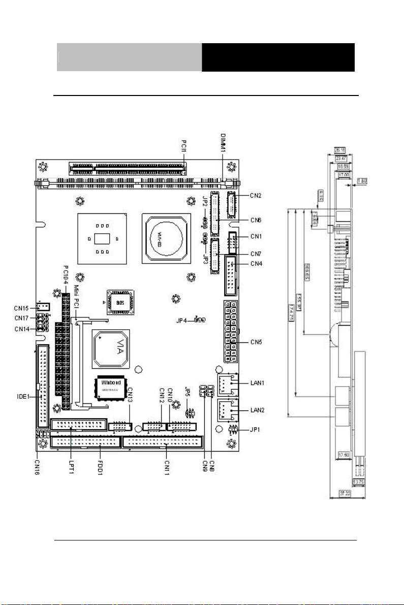
2.2 Location of Connectors and Jumpers
Component Side
Solder Side
Mini PCI
Chapter 2 Quick Installation Guide 2 - 3
Compact Board PCM- 6892 Rev.B
Chapter 2 Quick Installation Guide 2 - 4

Compact Board PCM-6892 Rev.B
2.3 Mechanical Drawing
Component Side
Chapter 2 Quick Installation Guide 2 - 5

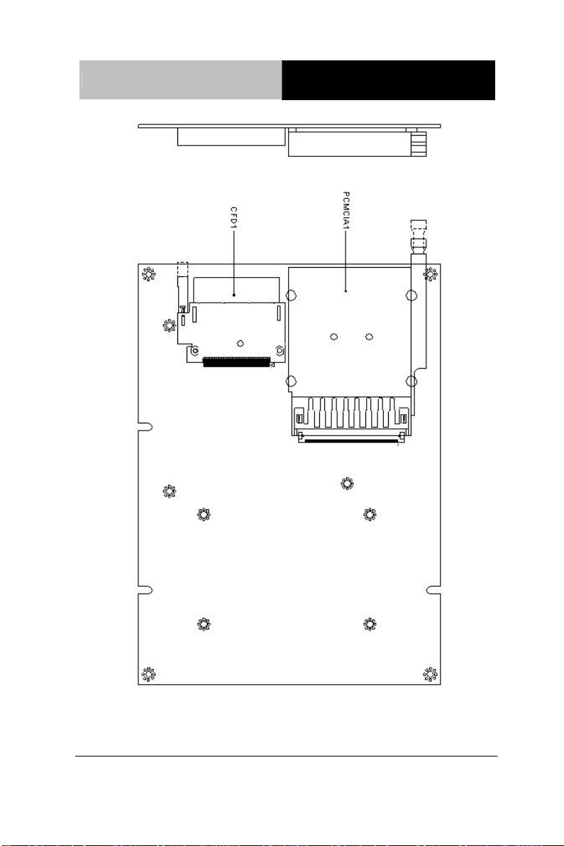
Compact Board PCM- 6892 Rev.B
Solder Side
Chapter 2 Quick Installation Guide 2 - 6

Compact Board PCM-6892 Rev.B
2.4 List of Jumpers
There are a number of jumpers in the board that allow you to configure your
system to suit your application.
The table below shows the function of each jumper in the board:
Jumpers
Label Function
JP1 Audio Out Selection
JP2 LCD Voltage Selection
JP3 TTL-LCD Clock Selection
JP4 Clear CMOS
JP5 COM2 Ring/+5V/+12V Selection
Chapter 2 Quick Installation Guide 2 - 7

Compact Board PCM- 6892 Rev.B
2.5 List of Connectors
There are a number of connectors in the board that allow you to configure
your system to suit your application. The table below shows the function of
each connector in the board:
Connectors
Label Function
CN1 TV_Out Connector
CN2 TTL_LCD Connector (DF-13 10 x 2)
CN4 VGA Display Connector
CN5 ATX Power Connector
CN6 TTL_LCD Connector (DF-13 20 x 2)
CN7 LVDS_LCD Connector (DF-13 15 x 2)
CN8 LAN1 LED Connector
CN9 LAN2 LED Connector
CN10 Audio Connector
CN11 COM1-4 Connector
CN12 USB0/1 Connector
CN13 USB2/3 Connector
CN14 IrDA Connector
CN15 Fan Connector
CN16 PS/2 Keyboard/Mouse Connector
CN17 Front Panel Connector
FDD-1 Floppy Connector
IDE1 EIDE Connector
Chapter 2 Quick Installation Guide 2 - 8

Compact Board PCM-6892 Rev.B
LPT1 LPT Port Connector
LAN1 10/100 or 100/1000Base-Tx Ethernet Connector
LAN2 10/100 or 100/1000Base-Tx Ethernet Connector
PCI1 PCI Slot
MPCI1 Mini PCI Slot
PCMCIA1 PCMCIA Slot
CFD1 CompactFlash Slot
P104-AB PC/104 Connector
P104-CD PC-104 Connector
DIMM1 DIMM Slot
Chapter 2 Quick Installation Guide 2 - 9

Compact Board PCM- 6892 Rev.B
3
2.6 Setting Jumpers
You configure your card to match the needs of your application by setting
jumpers. A jumper is the simplest kind of electric switch. It consists of two
metal pins and a small metal clip (often protected by a plastic cover) that
slides over the pins to connect them. To “close” a jumper you connect the
pins with the clip.
To “open” a jumper you remove the clip. Sometimes a jumper will have
three pins, labeled 1, 2 and 3. In this case you would connect either pins 1
and 2 or 2 and 3.
2
1
Open Closed Closed 2-3
A pair of needle-nose pliers may be helpful when working with jumpers.
If you have any doubts about the best hardware configuration for your
application, contact your local distributor or sales representative before you
make any change.
Generally, you simply need a standard cable to make most connections.
Chapter 2 Quick Installation Guide 2 - 10

Compact Board PCM-6892 Rev.B
2.7 Audio Out Selection (JP1)
JP1 Function
1-3, 2-4 W/O Amplifier
3-5, 4-6 W/ Amplifier (Default)
2.8 LCD Voltage Selection (JP2)
JP2 Function
1-2 +5V
2-3 +3.3V (Default)
2.9 TTL-LCD Clock Selection (JP3)
JP3 Function
1-2 CLK (Default)
2-3 Reverse CLK
Chapter 2 Quick Installation Guide 2 - 11

Compact Board PCM- 6892 Rev.B
2.10 Clear CMOS (JP4)
JP4 Function
1-2 Protected (Default)
2-3 Clear
2.11 COM2 Ring/+5V/+12V Selection (JP5)
JP5 Function
1-2 +12V
3-4 +5V
5-6 Ring (Default)
2.12 TV-Out Connector (CN1)
Pin Signal Pin Signal
1 Y 2 CVBS
3 GND 4 GND
5 C 6 N.C.
7 GND 8 N.C.
Chapter 2 Quick Installation Guide 2 - 12

Compact Board PCM-6892 Rev.B
2.13 TTL_LCD Connector (CN2)
Pin Signal Pin Signal
1 GND 2 GND
3 BLUE10 4 BLUE11
5 BLUE12 6 BLUE13
7 BLUE14 8 BLUE15
9 GREEN10 10 GREEN11
11 GREEN12 12 GREEN13
13 GREEN14 14 GREEN15
15 RED10 16 RED11
17 RED12 18 RED13
19 RED14 20 RED15
Chapter 2 Quick Installation Guide 2 - 13

Compact Board PCM- 6892 Rev.B
2.14 VGA Display Connector (CN4)
Pin Signal Pin Signal
1 RED 2 VGAVCC
3 GREEN 4 GND
5 BLUE 6 N.C.
7 N.C. 8 SDATA
9 GND 10 H
11 GND 12 V
13 GND 14 SCLK
15 GND 16 N.C.
2.15 ATX Power Connector (CN5)
Pin Signal Pin Signal
1 +3.3V 11 +3.3V
2 +3.3V 12 -12V
3 GND 13 GND
4 +5V 14 PS_ON
5 GND 15 GND
6 +5V 16 GND
7 GND 17 GND
8 POWER OK 18 -5V
9 +5VSB 19 +5V
10 +12V 20 +5V
Chapter 2 Quick Installation Guide 2 - 14

Compact Board PCM-6892 Rev.B
2.16 TTL_LCD Connector (CN6)
Pin Signal Pin Signal
1 +5V 2 +5V
3 GND 4 GND
5 +3.3V 6 +3.3V
7 ENBKL 8 GND
9 BLUE0 10 BLUE1
11 BLUE2 12 BLUE3
13 BLUE4 14 BLUE5
15 BLUE6 16 BLUE7
17 GREEN0 18 GREEN1
19 GREEN2 20 GREEN3
21 GREEN4 22 GREEN5
23 GREEN6 24 GREEN7
25 RED0 26 RED1
27 RED2 28 RED3
29 RED4 30 RED5
31 RED6 32 RED7
33 GND 34 GND
35 DOT_CLOCK 36 VSYNC
37 DE 38 HSYNC
39 N.C. 40 ENAEE
Chapter 2 Quick Installation Guide 2 - 15

Compact Board PCM- 6892 Rev.B
2.17 LVDS Connector (CN7)
Pin Signal Pin Signal
1 ENBKL 2 BKLCTL
3 PPVCC 4 GND
5 LVDS_CH1_TXCLK- 6 LVDS_CH1_TXCLK+
7 PPVCC 8 GND
9 LVDS_CH1_TX0- 10 LVDS_CH1_TX0+
11 LVDS_CH1_TX1- 12 LVDS_CH1_TX1+
13 LVDS_CH1_TX2- 14 LVDS_CH1_TX2+
15 N.C. 16 N.C.
17 I2C_DATA 18 I2C_CLK
19 LVDS_CH2_TX0- 20 LVDS_CH2_TX0+
21 LVDS_CH2_TX1- 22 LVDS_CH2_TX1+
23 LVDS_CH2_TX2- 24 LVDS_CH2_TX2+
25 N.C. 26 N.C.
27 PPVCC 28 GND
29 LVDS_CH2_TXCLK- 30 LVDS_CH2_TXCLK+
2.18 LAN1 LED Connector (CN8)
Pin Signal Pin Signal
1 RX LED 2 +3.3V
3 Link LED 4 +3.3V
5 TX LED 6 +3.3V
Chapter 2 Quick Installation Guide 2 - 16

Compact Board PCM-6892 Rev.B
2.19 LAN2 LED Connector (CN9)
Pin Signal Pin Signal
1 RX LED 2 +3.3V
3 Link LED 4 +3.3V
5 TX LED 6 +3.3V
2.20 Audio Connector (CN10)
Pin Signal Pin Signal
1 MIC_IN 2 MIC_+2.5V
3 LINE_IN_GND 4 CD_GND
5 LINE_IN_L 6 CD_IN_L
7 LINE_IN_R 8 CD_GND
9 LINE_IN_GND 10 CD_IN_R
11 LINE_OUT_L 12 LINE_OUT_R
13 LINE_OUT_GND 14 LINE_OUT_GND
Chapter 2 Quick Installation Guide 2 - 17

Compact Board PCM- 6892 Rev.B
2.21 COM1~4 Connector (CN11)
Pin Signal Pin Signal
1 DCD1 2 DSR1
3 RXD1 4 RTS1
5 TXD1 6 CTS1
7 DTR1 8 RI1
9 GND 10 N.C.
DCD2 (422TXD-/485DATA-)
11
12 DSR2
13 RXD2 (422RXD+) 14 RTS2
TXD2 (422TXD+/485DATA+)
15
16 CTS2
17 DTR2 (422RXD-) 18 RI2/+12V/+5V
19 GND 20 N.C.
21 DCD3 22 DSR3
23 RXD3 24 RTS3
25 TXD3 26 CTS3
27 DTR3 28 RI3
29 GND 30 N.C.
31 DCD4 32 DSR4
33 RXD4 34 RTS4
35 TXD4 36 CTS4
37 DTR4 38 RI4
39 GND 40 N.C.
Chapter 2 Quick Installation Guide 2 - 18

Compact Board PCM-6892 Rev.B
2.22 USB Connector (CN12)
Pin Signal Pin Signal
1 +5V 2 GND
3 USBD0- 4 GND
5 USBD0+ 6 USBD1+
7 GND 8 USBD19 GND 10 +5V
2.23 USB Connector (CN13)
Pin Signal Pin Signal
1 +5V 2 GND
3 USBD2- 4 GND
5 USBD2+ 6 USBD3+
7 GND 8 USBD39 GND 10 +5V
2.24 IrDA Connector (CN14)
Pin Signal
1 +5V
2 N.C.
3 IRRX
4 GND
5 IRTX
Chapter 2 Quick Installation Guide 2 - 19

Compact Board PCM- 6892 Rev.B
2.25 Fan Connector (CN15)
Pin Signal
1 Speed Sense
2 +5V
3 GND
2.26 PS/2 Keyboard & Mouse Connector (CN16)
Pin Signal Pin Signal
1 Keyboard DATA 2 Keyboard CLOCK
3 Keyboard GND 4 Keyboard VCC
5 Mouse DATA 6 Mouse CLOCK
7 N.C. 8 N.C.
2.27 Front Panel Connector (CN17)
Pin Signal Pin Signal
1 Power On Button (-) 2 Power On Button (+)
3 IDE LED (-) 4 IDE LED (+)
5 External Buzzer (-) 6 External Buzzer (+)
7 Power LED (-) 8 Power LED (+)
9 Reset Switch (-) 10 Reset Switch (+)
Chapter 2 Quick Installation Guide 2 - 20

Compact Board P C M - 6892 Rev.B
Chapter
3
Award
BIOS Setup
Chapter 3 Award BIOS Setup 3 - 1

Compact Board P C M - 6892 Rev.B
3.1 System test and initialization
These routines test and initialize board hardware. If the routines
encounter an error during the tests, you will either hear a few short
beeps or see an error message on the screen. There are two kinds of
errors: fatal and non-fatal. The system can usually continue the boot
up sequence with non-fatal errors. Non-fatal error messages usually
appear on the screen along with the following instructions:
Press <F1> to RESUME
Write down the message and press the F1 key to continue the boot
up sequence.
System configuration verification
These routines check the current system configuration against the
values stored in the CMOS memory. If they do not match, the
program outputs an error message. You will then need to run the
BIOS setup program to set the configuration information in
memory.
There are three situations in which you will need to change the
CMOS settings:
1. You are starting your system for the first time
2. You have changed the hardware attached to your system
3. The CMOS memory has lost power and the configuration
information has been erased.
The PCM-6892 REV.B CMOS memory has an integral lithium
battery backup for data retention. However, you will need to replace
the complete unit when it finally runs down.
Chapter 3 Award BIOS Setup 3 - 2

Compact Board P C M - 6892 Rev.B
3.2 Award BIOS Setup
Awards BIOS ROM has a built-in Setup program that allows users to
modify the basic system configuration. This type of information is
stored in battery-backed CMOS RAM so that it retains the Setup
information when the power is turned off.
Entering setup
Power on the computer and press <Del> immediately. This will
allow you to enter Setup.
Standard CMOS Features
Use this menu for basic system configuration. (Date, time, IDE, etc.)
Advanced BIOS Features
Use this menu to set the advanced features available on your system.
Advanced Chipset Features
Use this menu to change the values in the chipset registers and
optimize your system performance.
Integrated Peripherals
Use this menu to specify your settings for integrated peripherals.
(Primary slave, secondary slave, keyboard, mouse etc.)
Power Management Setup
Use this menu to specify your settings for power management.
(HDD power down, power on by ring etc.)
PnP/PCI Configurations
This entry appears if your system supports PnP/PCI.
PC Health Status
Chapter 3 Award BIOS Setup 3 - 3

Compact Board P C M - 6892 Rev.B
This menu shows you the status of PC.
Frequency/Voltage Control
This menu shows you the display of frequency/Voltage Control.
Load Fail-Safe Defaults
Use this menu to load the BIOS default values for the
minimal/stable performance for your system to operate.
Load Optimized Defaults
Use this menu to load the BIOS default values that are factory
settings for optimal performance system operations. While AWARD
has designated the custom BIOS to maximize performance, the
factory has the right to change these defaults to meet their needs.
Set Supervisor/User Password
Use this menu to set Supervisor/User Passwords.
Save and Exit Setup
Save CMOS value changes to CMOS and exit setup.
Exit Without Saving
Abandon all CMOS value changes and exit setup.
Chapter 3 Award BIOS Setup 3 - 4

Compact Board P C M - 6892 Rev.B
3.3 Standard CMOS Features
This standard Setup Menu allows users to configure system
components such as date, time, hard disk drive, floppy drive and
display. Once a field is highlighted, on-line help information is
displayed in the right box of the Menu screen.
3.4 Advanced BIOS Features
This sample screen contains the manufacturer’s default values for the
PCM-6892 REV.B
3.5 Advanced Chipset Features
This sample screen contains the manufacturer’s default values for the
PCM-6892 REV.B.
Chapter 3 Award BIOS Setup 3 - 5

Compact Board P C M - 6892 Rev.B
APM
ACPI
3.6 Integrated Peripherals
This sample screen contains the manufacturer’s default values for the
PCM-6892 REV.B.
PCMCIA Card Support Limitation List of PCM-6892 Rev.B
COM 3 and 4 need to be disable for supporting 16bit PCMCIA Card under Windows 98 SE
and Windows 2000 at both ACPI and APM mode
To disable COM3 and COM4 for supporting 16bit PCMCIA cards, please enable the
PCMCIA SERIQR option in CMOS setting.
Power mode OS COM 3, 4 16 bit PCMCIA 32 bit PCMCIA
Win 98
Win 2K
(5V only or AT)
Win XP
Win 98
Win 2K
(ATX)
Win XP
Enable F O
Disable O O
Enable F O
Disable O O
Enable O O
Disable O O
Enable F O
Disable O (*2) O (*2)
Enable F O
Disable O O
Enable O O
Disable O O
Remark:
*1. "F" means Failed to support. "O" means OK.
*2. Special AAEON driver is required for support PCMCIA Card under Windows 98 at
ACPI model (see chapter 4)
Chapter 3 Award BIOS Setup 3 - 6

Compact Board P C M - 6892 Rev.B
3.7 Power management Setup
This sample screen contains the manufacturer’s default values for the
PCM-6892 REV.B.
3.8 PnP/PCI configuration
This sample screen contains the manufacturer’s default values for the
PCM-6892 REV.B.
3.9 PC Health Status
This sample screen contains the manufacturer’s default values for the
PCM-6892 REV.B.
3.10 Frequency/Voltage control
This sample screen contains the manufacturer’s default values for
the PCM-6892 REV.B.
3.11 Load Fail-Safe Defaults
When you press <Enter> on this item you get a confirmation dialog
box with a message similar to:
Load Fail-Safe Default (Y/N)?
Pressing "Y" loads the BIOS default values for the most stable,
minimal performance system operations.
3.12 Load Optimized Defaults
When you press <Enter> on this item you get a confirmation dialog
box with a message similar to:
Load Optimized Defaults (Y/N)?
Pressing "Y" loads the default values that are manufacturer’s settings
for optimal performance system operations.
Chapter 3 Award BIOS Setup 3 - 7

Compact Board P C M - 6892 Rev.B
3.13 Set Supervisor/User Password
You can set either SUPERVISOR or USER PASSWORD, or both of
them. The difference between the two is that the supervisor password
allows unrestricted access to enter and change the options of the setup
menus, while the user password only allows entry to the program, but
not modify options.
To abort the process at any time, press Esc.
In the Security Option item in the BIOS Features Setup screen, select
System or Setup:
System Enter a password each time the system boots and when-
ever you enter Setup.
Setup Enter a password whenever you enter Setup.
NOTE: To clear the password, simply press Enter when asked to enter a
password. Then the password function is disabled.
3.14 Save & Exit Setup
If you select this option and press <Enter>, the values entered in the
setup utilities will be recorded in the chipset’s CMOS memory. The
microprocessor will check this every time you turn on your system and
compare this to what it finds as it checks the system. This record is
required for the system to operate.
3.15 Exit without saving
Selecting this option and pressing <Enter> allows you to exit the
Setup program without recording any new value or changing old one.
For more detailed information, you can refer to the "AAEON BIOS
Item Description.pdf" file in the CD for the meaning of each setting in this
chapter.
Chapter 3 Award BIOS Setup 3 - 8

Compact Board PCM- 6892 Rev.B
Chapter
4
Driver
Installation
Chapter 4 Driver Installation 4 - 1

Compact Board PCM- 6892 Rev.B
The PCM-6892 Rev.B comes with a CD-ROM that contains all
drivers and utilities that you need for setup the system.
Follow the sequence below to install the drivers:
Step 1 – Install VIA 4 in 1 driver
Step 2 – Install Graphic Driver
Step 3 – Install Audio Driver
Step 4 – Install Ethernet Driver
Step 5 – Install PCMCIA Driver (Win98 only)
Please read instructions below for further detailed installations.
Insert the PCM-6892 Rev.B CD-ROM into the CD-ROM Drive.
And install the drivers from Step 1 to Step 4 (5) in order.
Chapter 4 Driver Installation 4 - 2

Compact Board PCM- 6892 Rev.B
4.1 Step 1 – Install VIA 4 in 1 for Windows 98SE/2000/XP
1. Double click on the “executive file”.
2. Follow the instructions that the window will show you.
3. The system will help you install the driver automatically.
4.2 Step 2 – Install Graphic Driver for Windows 98SE/2000/XP
1. Choose the folder according to the OS you used and then double
click on the “Setup.exe” file.
2. Follow the instructions that the window will show you.
3. The system will help you install the driver automatically.
4. Please re-start your computer.
4.3 Step 3 – Install Audio Driver for Windows 98SE /2000/XP
1. Double click on the “Setup.exe” file.
2. Follow the instructions that the window will show you.
3. The system will help you install the driver automatically.
4. Please re-start your computer.
Chapter 4 Driver Installation 4 - 3

Compact Board PCM- 6892 Rev.B
4.4 Step 4 – Install Ethernet Driver for Windows 98SE /2000/XP
1. Double click on the “Setup.exe” file.
2. Follow the instructions that the window will show you.
3. The system will help you install the driver automatically.
4.5 Step 5 – Install AAEON PCMCIA Driver for Windows 98SE
1. Double click on the “TiSetup.exe” file.
2. Follow the instructions that the window will show you.
3. The system will help you install the driver automatically.
Chapter 4 Driver Installation 4 - 4

Compact Board PCM- 6892 Rev.B
Appendix
A
I/O Information
Appendix A I/O Information A - 1

Compact Board PCM- 6892 Rev.B
maskable
Monochrome Display and Printer Adapter
A.1 I/O Address Map
Address Description User Address
000-01F DMA Controller #1 000-000F
020-03F Interrupt Controller #1, Master 020-021
040-05F System Time 040-043
060-06F 8042 (Keyboard Controller) 060-064
070-07F
080-09F DMA Page Register 080-08F
0A0-0BF Interrupt Controller #2 0A0-0A1
0C0-0DF DMA Controller #2 0C0-0DF
0F0-0FF Math Coprpcessor 0F0-0FF
170-177 Secondary IDE Channel 170-177
1F0-1F7 Primary IDE Channel 1F0-1F7
278-27F Parallel Printer Port 2 (LPT3) 278-27F
2E8-2EF Serial Port 4 2E8-2EF
2F8-2FF Serial Port 2 2F8-2FF
378-37F Parallel Printer Port 1 (LPT2) 378-37F
Real time Clock, NMI (nonInterrupt) Mask
070-073
3B0-3BF
3D0-3DF EGA / VGA card 3D0-3DF
3E8-3EF Serial Port 3 3E8-3EF
3F0-3F7 Diskette Controller 3F2-3F7
3F8-3FF Serial Port 1 3F8-3FF
(LPT1)
A.2 1st MB Memory Address Map
Memory Address Description
00000-9FFFF System memory
A0000-BFFFF VGA buffer
C0000-CFFFF VGA BIOS
E0000-FFFFF System BIOS
Appendix A I/O Information A - 2
3B0-3BF

Compact Board PCM- 6892 Rev.B
A.3 IRQ Mapping Chart
IRQ0 System Timer IRQ8
IRQ1 Keyboard IRQ9
IRQ2 Cascade to IRQ Controller IRQ10 COM3
IRQ3 COM2 IRQ11 COM4
IRQ4 COM1 IRQ12 PS/2 mouse
IRQ5 Unused IRQ13 FPU
IRQ6 Floppy Disk Controller IRQ14 Primary IDE
IRQ7 Printer IRQ15 Secondary IDE
System CMOS / Real
time clock
Microsoft ACPI –
Compliant system
A.4 DMA Channel Assignments
DMA Channel Function
0 Available
1 Available
2 Standard Floppy Disk Controller
3 Available
4 Direct Memory Access Controller
5 Available
6 Available
7 Available
Appendix A I/O Information A - 3

Compact Board PCM - 6 892 Rev.B
Appendix
B
Programming the
Watchdog Timer
Appendix B Programming the Watchdog Timer B - 1

Compact Board PCM - 6 892 Rev.B
B.1 Programming the Watchdog Timer
PCM-6892 contains a watchdog timer reset pin. (GP16)
All reference material can be found on the following pages.
Appendix B Programming the Watchdog Timer B - 2

Compact Board PCM - 6 892 Rev.B
==================================================**
** Title : WatchDog Timer Setup Utility (for W83977 GP16) **
** Company : AAEON Technology Inc. **
** Compiler : Borland C ++ Version 3.0 **
**===================================================
===========*/
#include <dos.h>
#include <io.h>
#include <bios.h>
#include <stdio.h>
#include <stdlib.h>
#include <conio.h>
/* Set I/O Address : 370/371 or 3F0/3F1 */
#define IO_INDEX_PORT 0x370
#define IO_DATA_PORT 0x371
/* Set Watchdog reset pin : 12/13/16 */
#define watch_dog_output_GP 16
#define UNLOCK_DATA 0x87
#define LOCK_DATA 0xAA
#define DEVICE_REGISTER 0x07
void EnterConfigMode()
{
outportb(IO_INDEX_PORT, UNLOCK_DATA);
outportb(IO_INDEX_PORT, UNLOCK_DATA);
}
Appendix B Programming the Watchdog Timer B - 3

Compact Board PCM - 6 892 Rev.B
void ExitConfigMode()
{
outportb(IO_INDEX_PORT, LOCK_DATA);
}
void SelectDevice(unsigned char device)
{
outportb(IO_INDEX_PORT, DEVICE_REGISTER);
outportb(IO_DATA_PORT, device);
}
unsigned char ReadAData(short int reg)
{
outportb(IO_INDEX_PORT, reg);
return (inportb(IO_DATA_PORT));
}
void WriteAData(unsigned char reg, unsigned char data)
{
outportb(IO_INDEX_PORT, reg);
outportb(IO_DATA_PORT, data);
}
void SetWatchDogTime(unsigned char time_val)
{
EnterConfigMode();
SelectDevice(8);
WriteData(0x30, 0x01);
//Set Register F2
Appendix B Programming the Watchdog Timer B - 4

Compact Board PCM - 6 892 Rev.B
//Set Watch-Dog Timer 1~ 256
WriteAData(0xF2, time_val);
// set counter counts in second (or minute)
// Register F4 Bit 6 = 0/1 (minutes/seconds)
// For w83977EF only
WriteAData(0xF4, 0x40);
ExitConfigMode();
}
void init_w83977tf_aw_watchdog()
{
short int value;
//Enter W83977 Configure Mode
EnterConfigMode();
//Select Device 7
SelectDevice(7);
//Set Device Active
WriteAData(0x30, 0x01);
//caution:skip this step will be a mistake!!
if (watch_dog_output_GP==12)
{
//Set Register E2 to define GP12
WriteAData(0xE2, 0x0A);
}
else if(watch_dog_output_GP==13)
{
Appendix B Programming the Watchdog Timer B - 5

Compact Board PCM - 6 892 Rev.B
//Set Register E3 to define GP13
WriteAData(0xE3, 0x0A);
}
else if(watch_dog_output_GP==16)
{
//Set Register E6 to define GP16
WriteAData(0xE6, 0x0A);
}
//Select Device 8
SelectDevice(8);
WriteData(0x30, 0x01);
//Set Register F3
//keyboard and mouse interrupt reset Enable
//When Watch-Dog Time-out occurs,Enable POWER LED
output
WriteAData(0xF3, 0x0E);
//caution:skip this step will be a mistake!!
if (watch_dog_output_GP==12)
{
//Set Register 2A (PIN 57) Bit 7 = 0/1 (KBLOCK/GP12)
//set to GP12 for WD Rst
WriteAData(0x2A,ReadAData(0x2A)|0x80);
}
else if(watch_dog_output_GP==13)
{
Appendix B Programming the Watchdog Timer B - 6

Compact Board PCM - 6 892 Rev.B
//Set Register 2B (PIN 58) Bit 0 = 0/1 (KBLOCK/GP13)
//set to GP13 for WD Rst
WriteAData(0x2B,ReadAData(0x2B)|0x01);
}
else if(watch_dog_output_GP==16)
{
//Set Register 2C (PIN 119) Bit 5-4 = 01 (GP16)
//set to GP16 for WD Rst
WriteAData(0x2C,ReadAData(0x2C)|0x10);
}
//Exit W83977 Configure mode
ExitConfigMode();
}
void main(int argc, char* argv[])
{
int time_value=0;
char *ptr;
printf( inBond 83977 WatchDog Timer Setup Utility w
Version 1.0 \n" );
printf( copyright (c) 2000 AAEON Technology Inc.\n");C
printf( this version only for W83977 that using GP%d to T
Reset System.\n",watch_dog_output_GP);
if (argc == 1)
{
printf( n Syntax: WATCHDOG [time] \n" );\
Appendix B Programming the Watchdog Timer B - 7

Compact Board PCM - 6 892 Rev.B
printf(" time range : 1 ~ 256 \n\n" );
return ;
}
if (argc > 1)
{
ptr = argv[1];
time_value = atoi(ptr);
}
if (time_value > 0 && time_value < 256)
{
SetWatchDogTime((unsigned char) time_value);
init_w83977tf_aw_watchdog();
printf( atch Dog Timer set up : %d \n",time_value);W
}
}
Appendix B Programming the Watchdog Timer B - 8
 Loading...