

Page 1

Intel Express
10/100 Stackable Hub
User Guide
Page 2

This guide covers the following products:
Intel Express 10/100 Stackable Hub - 12-port TX hub. Product code EE110TX12.
Intel Express 10/100 Stackable Hub - 24-port TX hub. Product code EE110TX24.
Copyright © 1997, Intel Corporation. All rights reserved.
Intel Corporation, 5200 NE Elam Young Parkway, Hillsboro OR 97124-6497
Intel Corporation assumes no responsibility for errors or omissions in this manual. Nor does Intel make any commitment to
update the information contained herein.
* Other product and corporate names may be trademarks of other companies and are used only for explanation and to the
owners’ benefit, without intent to infringe.
First edition April 1997 662204-001
Page 3
Quick Start
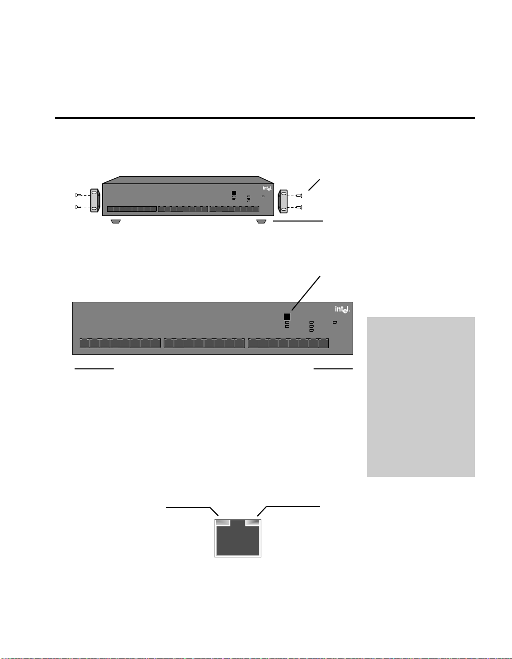
1. Install the Express 10/100 Stackable Hub in a rack or on a shelf or table,
plug it in, and turn the power on.
Rack: Use the four small screws to attach
the brackets to the hub. Use the four large
screws (not shown) to attach the hub to
the rack.
12
Intel Express
10/100 Stackable Hub
Change hub speed
Power
Collision
10
BASE-T
Managed
100
BASE-TX
Status
3
876
11
4
910
5
12
161514
13
17 18
19 24 2322
20
Green (left)
21
Link = solid
Activity = blink
Amber (right)
Wrong speed = blink
Disabled = solid
Shelf: Attach the four rubber feet to the
bottom before placing on a shelf or table.
2. Connect either 100BASE-TX devices or 10BASE-T devices to the ports.
The default hub speed is 100 Mbps. Press
Change Hub Speed to operate at 10 Mbps.
Intel Express
10/100 Stackable Hub
12
3
4
8
6
7
5
910
11
12
16
14
15
13
17 18
All ports operate at the same speed
For this connection Use this cable
Hub to server or workstation Straight-through TPE
Hub to print server Straight-through TPE
Hub to switch Crossover TPE
Hub to hub (10 Mbps only) Crossover TPE
3. Check the LEDs for links. You’re done.
Change hub speed
10
BASE-T
100
BASE-TX
19 24
22
20
21
Power
Collision
Managed
Status
Green (left)
23
Link = solid
Activity = blink
Amber (right)
Wrong speed = blink
Disabled = solid
Use Category 5 (CAT 5)
twisted-pair Ethernet
(TPE) cabling for 100
Mbps connections. Use
CAT 3, 4, or 5 TPE for
10 Mbps connections.
Cable distance can’t
exceed 100 meters
whether running at 10 or
100 Mbps.
Do not configure
attached devices for fullduplex. Hubs aren’t
capable of full-duplex.
On solid indicates a valid
link (may take up to 6
seconds). Blinking
indicates activity on the
port.
Green LED
(left side)
Amber LED
(right side)
Should normally be off. Blinking indicates a
speed mismatch. For example, the hub is
operating at 100 Mbps, but a 10 Mbps device
is connected to the port. See pages
10-11 for detailed descriptions.
Next steps (Optional)
Continue to the next page if you want to connect multiple hubs.
1
Page 4
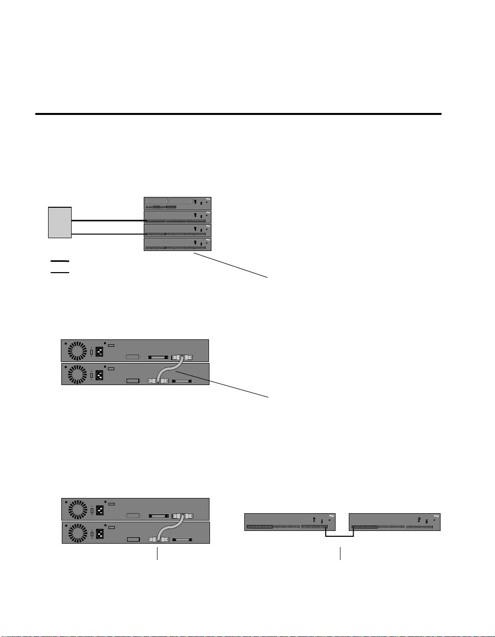
(Optional) Connecting multiple hubs
Connecting hubs running at 100 Mbps to hubs running at 10 Mbps
Use an Intel Cascade Cable to connect the hubs. Hubs running at 100 Mbps can talk to each other,
and hubs running at 10 Mbps can talk to each other. However, hubs running at 100 Mbps can’t talk
to hubs running at 10 Mbps without bridging equipment. See pages 5-7 for more information.
Optional bridging
equipment
876
3
910
12
4
5
876
3
910
12
4
5
876
3
910
12
4
5
876
3
910
12
4
5
Intel Express
10/100 Stackable Hub
Change hub speed
Collision
Power
10BASE-T
Managed
100BASE-TX
Status
Green (left)
11
12
Link = solid
Activity = blink
Amber (right)
Wrong speed = blink
Disabled = solid
11
12
161514
13
11
12
161514
13
11
12
161514
13
Intel Express
10/100 Stackable Hub
Change hub speed
Collision
10
BASE-T
Managed
100
BASE-TX
Status
Green (left)
19 24 2322
17 18
20
21
Link = solid
Activity = blink
Amber (right)
Wrong speed = blink
Disabled = solid
Intel Express
10/100 Stackable Hub
Change hub speed
Collision
10
BASE-T
Managed
100
BASE-TX
Status
Green (left)
19 24 2322
17 18
20
21
Link = solid
Activity = blink
Amber (right)
Wrong speed = blink
Disabled = solid
Intel Express
10/100 Stackable Hub
Change hub speed
Collision
10
BASE-T
Managed
100
BASE-TX
Status
Green (left)
19 24 2322
17 18
20
21
Link = solid
Activity = blink
Amber (right)
Wrong speed = blink
Disabled = solid
Hub 1 (100 Mbps)
Power
Hub 2 (100 Mbps)
Power
Hub 3 (10 Mbps)
Power
Hub 4 (10 Mbps)
Category 5 TPE (100m max.)
Category 3, 4, or 5 TPE (100m max.)
Connecting hubs running at 100 Mbps
Use an Intel Cascade Cable to connect the hubs. You can connect a maximum of eight hubs. See
page 4 for more information.
Hub 1
Hub 2
Hubs 1 and 2 are in one collision domain and
share 100 Mbps of bandwidth.
Hubs 3 and 4 are in a separate collision domain
from 1 and 2 and share 10 Mbps of bandwidth.
The optional bridging equipment allows hubs 1
and 2 to talk to hubs 3 and 4.
Connect hubs with an Intel Cascade Cable
(product code EE110CC)
Never connect hubs running at 100 Mbps
with TPE cable. Doing so violates the IEEE
802.3u Fast Ethernet standard for Class I
hubs.
Connect hubs with an Intel Cascade Cable
(product code EE110CC)
Connecting hubs running at 10 Mbps
Use an Intel Cascade Cable to stack the hubs or daisy-chain the hubs with TPE cable. All hubs in a
stack share 10 Mbps of bandwidth and count as one repeater hop. Hubs connected with TPE cable
count as two repeater hops. See page 4 for more information.
Hub 1
Hub 2
2
or
Connect hubs with an Intel Cascade Cable
(product code EE110CC)
3
876
12
11
910
4
12
5
13
Connect hubs with CAT 3, 4, or 5 TPE cable.
Limit distance to 100 meters.
Intel Express
10/100 Stackable Hub
Change hub speed
Power
Collision
10
BASE-T
Managed
100
BASE-TX
Status
161514
Green (left)
19 24 2322
17 18
20
21
Link = solid
Activity = blink
Amber (right)
Wrong speed = blink
Disabled = solid
3
876
12
11
910
4
12
5
Intel Express
10/100 Stackable Hub
Change hub speed
10
BASE-T
100
BASE-TX
161514
13
19 24 2322
17 18
20
21
Power
Collision
Managed
Status
Green (left)
Link = solid
Activity = blink
Amber (right)
Wrong speed = blink
Disabled = solid
Page 5

Contents
Overview ..................................................................................................................................................3
Connection Guidelines ............................................................................................................................. 4
Example Configurations .......................................................................................................................... 5
Mixed 10 Mbps and 100 Mbps environment ...................................................................................5
100 Mbps-only environment ............................................................................................................ 7
10 Mbps-only environment .............................................................................................................. 8
Understanding LEDs .............................................................................................................................. 10
Port LEDs........................................................................................................................................ 10
Unit LEDs .......................................................................................................................................11
Cabling Requirements ............................................................................................................................ 12
100BASE-TX requirements ............................................................................................................ 12
10BASE-T requirements ................................................................................................................ 12
100BASE-FX requirements ............................................................................................................ 12
Straight-through vs. crossover cables............................................................................................. 13
Troubleshooting .....................................................................................................................................14
Frequently Asked Questions .................................................................................................................. 15
Warranty ................................................................................................................................................. 17
Intel Automated Customer Support ....................................................................................................... 20
Overview
This guide covers both the 12- and 24-port versions of the Intel Express 10/100 Stackable Hub.
12
Intel Express
10/100 Stackable Hub
Change hub speed
Collision
Power
10BASE-T
Managed
100BASE-TX
3
4
5
Green (left)
876
11
910
12
Link = solid
Activity = blink
Amber (right)
Wrong speed = blink
Disabled = solid
Status
12
3
876
11
910
4
5
12
13
Intel Express
10/100 Stackable Hub
Change hub speed
Power
Collision
10
BASE-T
Managed
100
BASE-TX
Status
161514
19 24 2322
17 18
Green (left)
20
21
Link = solid
Activity = blink
Amber (right)
Wrong speed = blink
Disabled = solid
• Intel product code: EE110TX12 • Intel product code: EE110TX24
• 12 fixed TPE ports • 24 fixed TPE ports
• Stack eight hubs (mixed 12- or 24-port) • Stack eight hubs (mixed 12- or 24-port)
• Hub management through optional • Hub management requires a 12-port
Management Module (product code EE110MM) 10/100 Stackable Hub in same stack
• Bridging or full-duplex support through optional
Ethernet Module (product code EE110EM)
• 100BASE-FX support through optional
Fiber Module (product code EE110FX)
33
Page 6

OK
100 Mbps hubs
No!
Intel Express
10/100 Stackable Hub
Change hub speed
Power
Collision
10
BASE-T
Managed
100
BASE-TX
Status
Green (left)
11
8765910
3
1 2
12
4
161514
13
24 2322
19
17 18
20
21
3
11
12
87659 10
4
12
161514
13
Link = solid
Activity = blink
Amber (right)
Wrong speed = blink
Disabled = solid
17 18
100 Mbps hubs
OK
10 Mbps hubs
OK
Intel Express
10/100 Stackable Hub
Change hub speed
Power
Collision
10
BASE-T
Managed
100
BASE-TX
Status
Green (left)
11
8765910
3
1 2
12
4
161514
13
24 2322
19
17 18
20
21
3
11
12
87659 10
4
12
161514
13
Link = solid
Activity = blink
Amber (right)
Wrong speed = blink
Disabled = solid
10 Mbps hubs
NOTE
The acronym TPE (twisted-pair
Ethernet) refers to Category 3,
4, or 5 unshielded twisted-pair
(UTP) cabling or Category 5
shielded twisted-pair (STP)
cabling.
17 18
Connection Guidelines
Connecting 100BASE-TX devices
• Use Category 5 twisted-pair Ethernet (CAT 5 TPE) cable.
• Always limit the distance between devices connected with TPE
cable to 100 meters (the IEEE specification requires this).
• Use a crossover cable to connect the hub to a switch. Use a
straight-through cable to connect the hub to a server or
workstation. See pages 12-13 for more information on cabling.
• Never connect two hubs operating at 100 Mbps with TPE cabling
Intel Express
10/100 Stackable Hub
Change hub speed
Collision
10
BASE-T
Managed
100
BASE-TX
Status
24 2322
19
20
21
Intel Express
10/100 Stackable Hub
Change hub speed
Collision
10
BASE-T
Managed
100
BASE-TX
Status
Green (left)
24 2322
19
20
21
Link = solid
Activity = blink
Amber (right)
Wrong speed = blink
Disabled = solid
(this violates the IEEE 802.3u Fast Ethernet specification for
Power
Green (left)
Link = solid
Activity = blink
Amber (right)
Wrong speed = blink
Disabled = solid
Class I hubs). You must use an Intel Cascade Cable.
• Never connect a device to the hub at full-duplex. Only the
optional Ethernet Module or Fiber Module supports full-duplex.
Connecting 10BASE-T devices
• Use Category 3, 4, or 5 twisted-pair Ethernet (CAT 3, 4, or 5
TPE) cable.
• Use a crossover cable to connect a hub to another hub or a switch.
Use a straight-through cable to connect a hub to a server or
workstation. See pages 12-13 for more information on cabling.
• Follow the 5-4-3-2-1 general rule when daisy-chaining 10 Mbps
hubs. See page 9 for more information.
• Always limit the distance between devices connected with TPE
Power
cable to 100 meters (the IEEE specification requires this).
• Use an Intel Cascade Cable to connect hubs when:
- you want all hubs in the stack to count as a single repeater.
- you want to use a single Management Module to manage all
hubs in the stack.
• Never connect a device to the hub at full-duplex. Only the
optional Ethernet Module or Fiber Module supports full-duplex.
4
Page 7
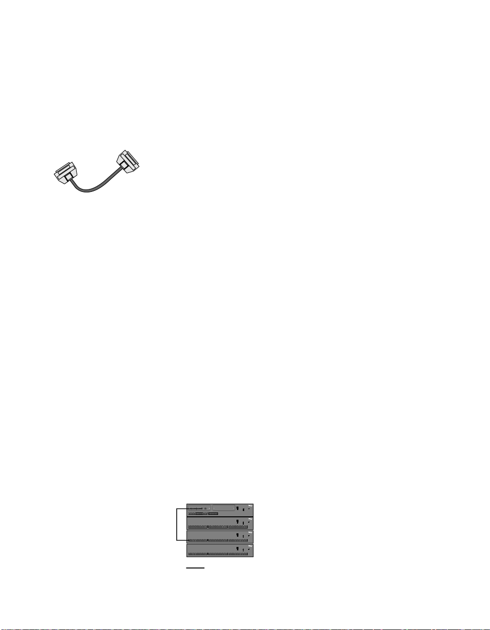
NOTE
You must use an Intel Cascade
Cable to connect hubs running
at 100 Mbps. Do not daisychain hubs with TPE crossover
cabling.
Intel Cascade Cable
(product code EE110CC)
NOTE
In a managed stack of hubs,
the optional Management Module can communicate with all
hubs, regardless of speed.
Example Configurations
Mixed 10 Mbps and 100 Mbps environment
A stack of Express 10/100 Stackable Hubs can contain hubs running
at both 10 and 100 Mbps. However, the hubs running at 10 Mbps and
the hubs running at 100 Mbps are on separate network segments.
These two segments can’t communicate with each other unless you
use another device to bridge them.
There are several ways to bridge the 10 Mbps and 100 Mbps
segments:
• Use the optional Intel Express Stackable Hub Ethernet Module
(product code EE110EM).
• Use a switch capable of both 10 Mbps and 100 Mbps operation,
such as the Intel Express 10/100 Fast Ethernet Switch (product
code ES101TX).
• Use a server with two 10/100 adapters installed.
• Use the Intel Express 10/100 Downlink (product code EC100DL).
• Use a router capable of both 10 Mbps and 100 Mbps operation
(not described here).
The Ethernet Module acts
as a switch port plugged
into a hub. It has the added
benefit of connecting to a
switch or server configured
at full-duplex.
This is the only time you can
connect an Express 10/100
Stackable Hub to a device
at full-duplex.
Bridging with the Intel Express Stackable Hub
Ethernet Module (sold separately)
The Ethernet Module plugs into the expansion slot of a 12-port hub
running at either 10 Mbps or 100 Mbps. Simply plug the module into
a hub running at one speed and connect to a hub running at the other
speed, and the Ethernet Module bridges the two collision domains.
Express 10/100
Stackable Hubs
Ethernet Module
Auto-negotiate
Auto-negotiate
Full-duplex
100 Mbps
Half-duplex
10 Mbps
Green (left)
876
11
3
910
12
12
4
5
Link = solid
Activity = blink
Amber (right)
Wrong speed = blink
Disabled = solid
876
11
3
910
12
12
4
5
161514
13
17 18
876
11
3
910
12
12
4
5
161514
13
17 18
876
11
3
910
12
12
4
5
161514
13
17 18
Category 3, 4, or 5 TPE
Intel Express
10/100 Stackable Hub
Change hub speed
Power
Collision
10BASE-T
Managed
100BASE-TX
Status
Hub 1 (100 Mbps)
Intel Express
10/100 Stackable Hub
Change hub speed
Power
Collision
10
BASE-T
Managed
100
BASE-TX
Status
Green (left)
Hub 2 (100 Mbps)
19 24 2322
20
21
Link = solid
Activity = blink
Amber (right)
Wrong speed = blink
Disabled = solid
Intel Express
10/100 Stackable Hub
Change hub speed
Power
Collision
10
BASE-T
Managed
100
BASE-TX
Status
Hub 3 (10 Mbps)
Green (left)
19 24 2322
20
21
Link = solid
Activity = blink
Amber (right)
Wrong speed = blink
Disabled = solid
Intel Express
10/100 Stackable Hub
Change hub speed
Power
Collision
10
BASE-T
Managed
100
BASE-TX
Status
Hub 4 (10 Mbps)
Green (left)
19 24 2322
20
21
Link = solid
Activity = blink
Amber (right)
Wrong speed = blink
Disabled = solid
If you plug the Ethernet Module
into a hub running at 100 Mbps,
connect it to a hub running at
10 Mbps with CAT 3, 4, or 5
TPE.
If you plug the Ethernet Module
into a hub running at 10 Mbps,
connect it to a hub running at
100 Mbps with CAT 5 TPE.
5
Page 8

The benefits of the switch
are its port density (eight
base ports expandable to
12), performance, and
manageability.
Bridging with the Express 10/100 Fast Ethernet
Switch
A switch with individual ports capable of operating at 10 or 100 Mbps
can bridge 10 Mbps and 100 Mbps segments. No configuration of
your network operating system is needed.
Hubs 1 and 2 are in one
collision domain and share
100 Mbps of bandwidth.
Hubs 3 and 4 are in a
separate collision domain
from 1 and 2 and share 10
Mbps of bandwidth.
The server handles the
bridging and allows hubs
1 and 2 to talk to hubs
3 and 4.
Express 10/100
Fast Ethernet Switch
MDI
MDI-X MDI-X MDI-X MDI-X MDI-X MDI-X MDI-X MDI-X
MDI
MDI-X MDI-X MDI-X MDI-X MDI-X MDI-X MDI-X MDI-X
Coll/
Coll/
Coll/
Coll/
Fdpx
Fdpx
Fdpx
Fdpx
Xmt
Link
Xmt Link
Xmt
Link
Xmt Link
Rcv100Flow
Rcv100Flow
Rcv100Flow
Rcv100Flow
Port 1
Port 2
Port 1
Port 2
Intel Express 10/100
Fast Ethernet Switch
Console
Console
Coll/
Coll/
Coll/
Coll/
Coll/
Coll/
Coll/
Coll/
Coll/
Coll/
Coll/
Coll/
Fdpx
Fdpx
Fdpx
Fdpx
Fdpx
Fdpx
Fdpx
Fdpx
Fdpx
Fdpx
Fdpx
Fdpx
Xmt Link
Xmt Link
Xmt Link
Xmt Link
Xmt Link
Rcv100Flow
Rcv100Flow
Port 3
Port 4
Port 3
Port 4
SNMP Power
Xmt Link
Xmt Link
Xmt Link
Xmt Link
SNMP Power
Xmt Link
Xmt Link
Xmt Link
Rcv100Flow
MgmtFault
Rcv100Flow
MgmtFault
Rcv100Flow
Rcv100Flow
Rcv100Flow
Rcv100Flow
Rcv100Flow
Rcv100Flow
Rcv100Flow
Rcv100Flow
9600-N-1
9600-N-1
Port 8
Port 5
Port 6
Port 7
Port 8
Port 5
Port 6
Port 7
Express 10/100
Stackable Hubs
Green (left)
876
11
3
910
12
12
4
5
Link = solid
Activity = blink
Amber (right)
Wrong speed = blink
Disabled = solid
876
11
3
910
12
12
4
5
161514
13
876
11
3
910
12
12
4
5
161514
13
876
11
3
910
12
12
4
5
161514
13
Intel Express
10/100 Stackable Hub
Change hub speed
Collision
10BASE-T
Managed
100BASE-TX
Status
Intel Express
10/100 Stackable Hub
Change hub speed
Collision
10
BASE-T
Managed
100
BASE-TX
Status
19 24 2322
17 18
20
21
Intel Express
10/100 Stackable Hub
Change hub speed
Collision
10
BASE-T
Managed
100
BASE-TX
Status
19 24 2322
17 18
20
21
Intel Express
10/100 Stackable Hub
Change hub speed
Collision
10
BASE-T
Managed
100
BASE-TX
Status
19 24 2322
17 18
20
21
Power
Hub 1 (100 Mbps)
Power
Green (left)
Hub 2 (100 Mbps)
Link = solid
Activity = blink
Amber (right)
Wrong speed = blink
Disabled = solid
Power
Hub 3 (10 Mbps)
Green (left)
Link = solid
Activity = blink
Amber (right)
Wrong speed = blink
Disabled = solid
Power
Hub 4 (10 Mbps)
Green (left)
Link = solid
Activity = blink
Amber (right)
Wrong speed = blink
Disabled = solid
Category 5 TPE (100m max.)
Category 3, 4, or 5 TPE (100m max.)
Bridging with a server equipped with two 10/100
adapters (requires NOS that supports multiprotocol routing)
If you’re using a NOS that supports multi-protocol routing, such as
Novell NetWare* or Windows NT*, an inexpensive way to bridge the
10 Mbps and 100 Mbps segments is to install two 10/100 adapters
(one running at 10 Mbps and the other at 100 Mbps) in your server
and let the server bridge the segments.
Check with your NOS manufacturer to verify support for multiprotocol routing.
Server equipped with
two 10/100 NICs
Category 5 TPE (100m max.)
Category 3, 4, or 5 TPE (100m max.)
Express 10/100
Stackable Hubs
Green (left)
876
11
3
910
12
12
4
5
Link = solid
Activity = blink
Amber (right)
Wrong speed = blink
Disabled = solid
876
11
3
910
12
12
4
5
161514
13
876
11
3
910
12
12
4
5
161514
13
876
11
3
910
12
12
4
5
161514
13
Intel Express
10/100 Stackable Hub
Change hub speed
Collision
10BASE-T
Managed
100BASE-TX
Status
Intel Express
10/100 Stackable Hub
Change hub speed
Collision
10
BASE-T
Managed
100
BASE-TX
Status
Green (left)
19 24 2322
17 18
20
21
Link = solid
Activity = blink
Amber (right)
Wrong speed = blink
Disabled = solid
Intel Express
10/100 Stackable Hub
Change hub speed
Collision
10
BASE-T
Managed
100
BASE-TX
Status
Green (left)
19 24 2322
17 18
20
21
Link = solid
Activity = blink
Amber (right)
Wrong speed = blink
Disabled = solid
Intel Express
10/100 Stackable Hub
Change hub speed
Collision
10
BASE-T
Managed
100
BASE-TX
Status
Green (left)
19 24 2322
17 18
20
21
Link = solid
Activity = blink
Amber (right)
Wrong speed = blink
Disabled = solid
Power
Hub 1 (100 Mbps)
Power
Hub 2 (100 Mbps)
Power
Hub 3 (10 Mbps)
Power
Hub 4 (10 Mbps)
6
Page 9
Here, the 2-port 10/100
Downlink bridges the two
100 Mbps hubs to the two
10 Mbps hubs.
The benefits of using the
Downlink are its low cost
and simplicity. Just plug the
hubs into the Downlink; it
takes care of the rest.
Bridging with the Express 10/100 Downlink
The Express 10/100 Downlink has two ports that operate at either 10
or 100 Mbps. Each port automatically senses the speed of the attached
device. All you need to do is set the speed of the hubs. No
configuration of your network operating system is needed.
Intel Express
10/100 Downlink
Configuring:
1. Long press to start
4. (To set duplex) Short press to set Port 1
Intel Express 10/100 Downlink
2. Short press to cycle
5. (To set duplex) Long press to cycle
3. Long press to select
6. (To set duplex) Short press to set Port 2
View %
Port 1
Power
Configure
View Utilization %
View Forward %
View Filter %
View Collision %
Set Full/Half Duplex
Run Diagnostics
Port 2
1 510 20 3550 7090+
LinkXmt Rcv Full100 Mbps
Category 5 TPE (100m max.)
Category 3, 4, or 5 TPE (100m max.)
Express 10/100
Stackable Hubs
Green (left)
876
11
3
910
12
12
4
5
Link = solid
Activity = blink
Amber (right)
Wrong speed = blink
Disabled = solid
876
11
3
910
12
12
4
5
13
876
11
3
910
12
12
4
5
13
876
11
3
910
12
12
4
5
13
Intel Express
10/100 Stackable Hub
Change hub speed
Power
Collision
10BASE-T
Managed
100BASE-TX
Status
Hub 1 (100 Mbps)
Intel Express
10/100 Stackable Hub
Change hub speed
Power
Collision
10
BASE-T
Managed
100
BASE-TX
Status
Green (left)
19 24 2322
17 18
20
21
Link = solid
Activity = blink
Amber (right)
Wrong speed = blink
Disabled = solid
Intel Express
10/100 Stackable Hub
Change hub speed
Collision
10
BASE-T
Managed
100
BASE-TX
Status
Green (left)
19 24 2322
17 18
20
21
Link = solid
Activity = blink
Amber (right)
Wrong speed = blink
Disabled = solid
Intel Express
10/100 Stackable Hub
Change hub speed
Collision
10
BASE-T
Managed
100
BASE-TX
Status
Green (left)
19 24 2322
17 18
20
21
Link = solid
Activity = blink
Amber (right)
Wrong speed = blink
Disabled = solid
Hub 2 (100 Mbps)
Power
Hub 3 (10 Mbps)
Power
Hub 4 (10 Mbps)
161514
161514
161514
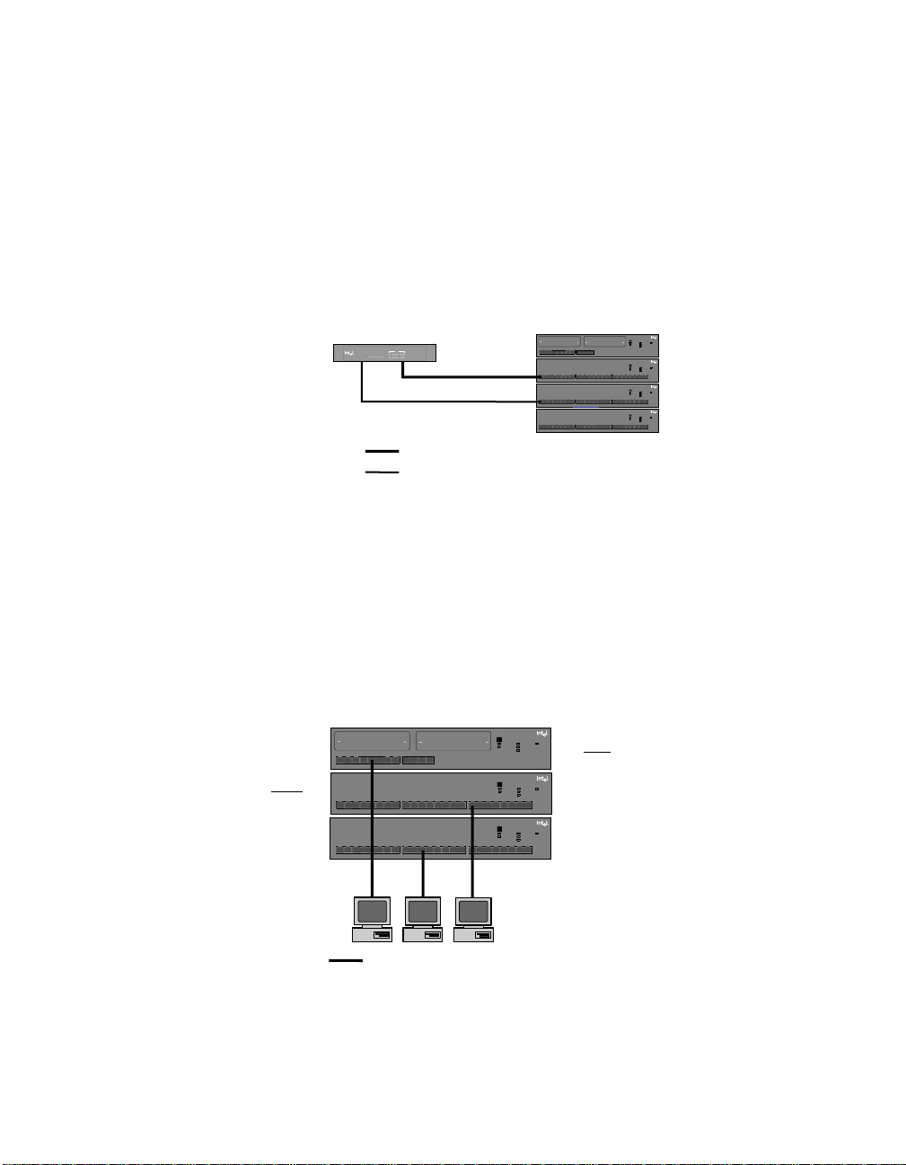
100 Mbps-only environment
In the 100-Mbps only environment, you can only connect hubs using
an Intel Cascade Cable. You must also use CAT 5 TPE cabling to
connect devices (switches, workstations, servers, and so on). The
distance between a port and an attached device can’t exceed
100 meters.
100 Mbps
shared among
all hubs in
stack
12
12
12
3
4
5
3
4
5
5
3
4
5
Green (left)
876
11
910
12
Link = solid
Activity = blink
Amber (right)
Wrong speed = blink
Disabled = solid
876
11
910
12
13
876
11
910
12
13
Category 5 TPE (100m max.)
Intel Express
10/100 Stackable Hub
Change hub speed
Power
Collision
10BASE-T
Managed
100BASE-TX
Status
Intel Express
10/100 Stackable Hub
Change hub speed
Power
Collision
10
BASE-T
Managed
100
BASE-TX
Status
19 24 2322
20
19 24 2322
20
21
Intel Express
10/100 Stackable Hub
Change hub speed
10
BASE-T
100
BASE-TX
21
Green (left)
Link = solid
Activity = blink
Amber (right)
Wrong speed = blink
Disabled = solid
Power
Collision
Managed
Status
Green (left)
Link = solid
Activity = blink
Amber (right)
Wrong speed = blink
Disabled = solid
161514
17 18
161514
17 18
If you intend to install an optional
Management Module in a
12-port hub, place the hub at
eye level. This makes it easier
to read the module’s LCD panel.
7
Page 10

100 Mbps
shared among
all hubs in stack
Extending the 100 Mbps network topology
You can extend the network topology only by connecting hubs to a
switch, bridge, or router. You can’t extend the topology by daisychaining hubs together. In the example below, the network diameter is
extended to 400 meters by connecting the two hub stacks to an Intel
Express 10/100 Fast Ethernet Switch. Each stack is a separate
collision domain.
Express 10/100
Fast Ethernet Switch
MDI
MDI-X MDI-X MDI-X MDI-X MDI-X MDI-X MDI-X MDI-X
MDI
MDI-X MDI-X MDI-X MDI-X MDI-X MDI-X MDI-X MDI-X
Coll/
Coll/
Coll/
Coll/
Coll/
Coll/
Fdpx
Fdpx
Fdpx
Fdpx
Fdpx
Fdpx
Xmt
Link
Xmt Link
Xmt Link
Xmt
Link
Xmt Link
Xmt Link
Rcv100Flow
Rcv100Flow
Rcv100Flow
Rcv100Flow
Rcv100Flow
Rcv100Flow
Port 1
Port 3
Port 2
Port 1
Port 3
Port 2
Intel Express
10/100 Stackable Hub
Change hub speed
Power
Collision
10BASE-T
Managed
100BASE-TX
Status
Green (left)
876
11
3
910
12
12
4
5
Link = solid
Activity = blink
Amber (right)
Wrong speed = blink
Disabled = solid
876
11
3
910
12
12
4
5
13
5
3
12
876
11
910
4
12
5
13
100m
Intel Express
10/100 Stackable Hub
Change hub speed
Power
Collision
10
BASE-T
Managed
100
BASE-TX
Status
Green (left)
161514
19 24 2322
17 18
20
21
Link = solid
Activity = blink
Amber (right)
Wrong speed = blink
Disabled = solid
Intel Express
10/100 Stackable Hub
Change hub speed
Power
Collision
10
BASE-T
Managed
100
BASE-TX
Status
Green (left)
161514
19 24 2322
17 18
20
21
Link = solid
Activity = blink
Amber (right)
Wrong speed = blink
Disabled = solid
100m
Intel Express 10/100
Fast Ethernet Switch
Console
Console
Coll/
Coll/
Coll/
Coll/
Coll/
Coll/
Coll/
Coll/
Coll/
Coll/
Fdpx
Fdpx
Fdpx
Fdpx
Fdpx
Fdpx
Fdpx
Fdpx
Fdpx
Fdpx
Xmt Link
SNMP Power
Xmt Link
Xmt Link
Xmt Link
Rcv100Flow
Rcv100Flow
Port 4
Port 4
SNMP Power
Xmt Link
Xmt Link
Xmt Link
Xmt Link
Xmt Link
Xmt Link
Rcv100Flow
MgmtFault
Rcv100Flow
Rcv100Flow
Rcv100Flow
Rcv100Flow
MgmtFault
Rcv100Flow
Rcv100Flow
Rcv100Flow
9600-N-1
9600-N-1
Port 8
Port 8
Port 5
Port 6
Port 7
Port 5
Port 6
Port 7
100m
3
12
4
5
3
12
4
5
5
3
12
4
5
Intel Express
10/100 Stackable Hub
Change hub speed
Power
Collision
10BASE-T
Managed
100BASE-TX
Status
Green (left)
876
11
910
12
Link = solid
Activity = blink
Amber (right)
Wrong speed = blink
Disabled = solid
Intel Express
10/100 Stackable Hub
Change hub speed
Power
Collision
10
BASE-T
Managed
100
BASE-TX
Status
876
11
910
12
876
11
910
12
Green (left)
161514
13
19 24 2322
17 18
20
21
Link = solid
Activity = blink
Amber (right)
Wrong speed = blink
Disabled = solid
Intel Express
10/100 Stackable Hub
Change hub speed
Power
Collision
10
BASE-T
Managed
100
BASE-TX
Status
Green (left)
161514
13
19 24 2322
17 18
20
21
Link = solid
Activity = blink
Amber (right)
Wrong speed = blink
Disabled = solid
100 Mbps
shared among
all hubs in stack
100m
If you intend to install an
optional Management
Module in a 12-port hub,
place the hub at eye
level. This makes it
easier to read the
module’s LCD panel.
Category 5 TPE (100m max.)
10 Mbps-only environment
In a 10-Mbps only environment, you can connect hubs using an Intel
Cascade Cable or CAT 3, 4, or 5 TPE cables. Connect to devices
(switches, workstations, servers, and so on) with CAT 3, 4, or 5 TPE
cables. The distance between hubs or between a port and an attached
device can’t exceed 100 meters when using TPE cabling.
Intel Express
10/100 Stackable Hub
Change hub speed
Power
Collision
10BASE-T
Managed
100BASE-TX
Green (left)
876
11
910
12
Link = solid
Activity = blink
Amber (right)
Wrong speed = blink
Disabled = solid
876
11
910
12
161514
13
876
11
910
12
161514
13
12
12
12
3
4
5
3
4
5
5
3
4
5
Category 3, 4, or 5 TPE (100m max.)
Status
Intel Express
10/100 Stackable Hub
Change hub speed
Power
Collision
10
BASE-T
Managed
100
BASE-TX
Status
Green (left)
19 24 2322
17 18
20
21
Link = solid
Activity = blink
Amber (right)
Wrong speed = blink
Disabled = solid
Intel Express
10/100 Stackable Hub
Change hub speed
Power
Collision
10
BASE-T
Managed
100
BASE-TX
Status
Green (left)
19 24 2322
17 18
20
21
Link = solid
Activity = blink
Amber (right)
Wrong speed = blink
Disabled = solid
All hubs in a stack share
10 Mbps of bandwidth and
count as one repeater hop.
8
Page 11

10 Mbps
shared among
all hubs in
stack
Extending the 10 Mbps network topology
To extend the 10BASE-T network topology, you can attach hubs to a
switch or daisy-chain the hubs using TPE cabling.
If you attach a stack of hubs to a switch, each stack gets its own
10 Mbps of bandwidth.
Attaching hubs to a switch
The illustration below shows two stacks of Express 10/100 Stackable
Hubs operating at 10 Mbps attached to Intel Express 10/100 Switch
ports also operating at 10 Mbps. Each TPE cable is extended to 100
meters, from workstation to hub and hub to switch. The total network
topology is extended to 400 meters.
Express 10/100
Fast Ethernet Switch
MDI
MDI-X MDI-X MDI-X MDI-X MDI-X MDI-X MDI-X MDI-X
MDI
MDI-X MDI-X MDI-X MDI-X MDI-X MDI-X MDI-X MDI-X
Coll/
Coll/
Coll/
Coll/
Coll/
Coll/
Fdpx
Fdpx
Fdpx
Fdpx
Fdpx
Fdpx
Xmt
Link
Xmt Link
Xmt Link
Xmt
Link
Xmt Link
Xmt Link
Rcv100Flow
Rcv100Flow
Rcv100Flow
Rcv100Flow
Rcv100Flow
Rcv100Flow
Port 1
Port 3
Port 2
Port 1
Port 3
Port 2
Intel Express
10/100 Stackable Hub
Change hub speed
Power
Collision
10BASE-T
Managed
100BASE-TX
Status
Green (left)
876
11
3
910
12
12
4
5
Link = solid
Activity = blink
Amber (right)
Wrong speed = blink
Disabled = solid
Intel Express
10/100 Stackable Hub
Change hub speed
Power
Collision
10
BASE-T
Managed
100
BASE-TX
Status
876
11
3
910
12
4
5
5
3
12
876
11
910
4
5
Green (left)
12
161514
13
19 24 2322
17 18
20
21
Link = solid
Activity = blink
Amber (right)
Wrong speed = blink
Disabled = solid
Intel Express
10/100 Stackable Hub
Change hub speed
Power
Collision
10
BASE-T
Managed
100
BASE-TX
Status
Green (left)
12
161514
13
19 24 2322
17 18
20
21
Link = solid
Activity = blink
Amber (right)
Wrong speed = blink
Disabled = solid
Intel Express 10/100
Fast Ethernet Switch
Console
Console
Coll/
Coll/
Coll/
Coll/
Coll/
Coll/
Coll/
Coll/
Coll/
Coll/
Fdpx
Fdpx
Fdpx
Fdpx
Fdpx
Fdpx
Fdpx
Fdpx
Fdpx
Fdpx
Xmt Link
SNMP Power
Xmt Link
Xmt Link
Xmt Link
Rcv100Flow
Rcv100Flow
Port 4
Port 4
SNMP Power
Xmt Link
Xmt Link
Xmt Link
Xmt Link
Xmt Link
Xmt Link
Rcv100Flow
MgmtFault
Rcv100Flow
Rcv100Flow
Rcv100Flow
Rcv100Flow
MgmtFault
Rcv100Flow
Rcv100Flow
Rcv100Flow
9600-N-1
9600-N-1
Port 8
Port 8
Port 5
Port 6
Port 7
Port 5
Port 6
Port 7
3
12
4
5
3
12
4
5
5
3
12
4
5
Intel Express
10/100 Stackable Hub
Change hub speed
Power
Collision
10BASE-T
Managed
100BASE-TX
Status
Green (left)
876
11
910
12
Link = solid
Activity = blink
Amber (right)
Wrong speed = blink
Disabled = solid
Intel Express
10/100 Stackable Hub
Change hub speed
Power
Collision
10
BASE-T
Managed
100
BASE-TX
Status
876
11
910
12
876
11
910
12
Green (left)
161514
13
19 24 2322
17 18
20
21
Link = solid
Activity = blink
Amber (right)
Wrong speed = blink
Disabled = solid
Intel Express
10/100 Stackable Hub
Change hub speed
Power
Collision
10
BASE-T
Managed
100
BASE-TX
Status
Green (left)
161514
13
19 24 2322
17 18
20
21
Link = solid
Activity = blink
Amber (right)
Wrong speed = blink
Disabled = solid
10 Mbps
shared among
all hubs in
stack
Follow the 5-4-3-2-1
general rule when daisychaining 10 Mbps hubs
Five
hubs (or hub stacks) are
allowed.
Four
segments.
Three
hub stacks can have
nodes attached.
Two
hub stacks can’t be
populated and are extensions
only.
All of this makes
sion domain with a maximum of 576 stations (if
you’re using 24-port Express
10/100 Hubs).
one
colli-
Category 3, 4, or 5 TPE (100m max.)
Daisy-chaining hubs (10 Mbps only)
Hubs can be connected using an Intel Cascade Cable, or “daisy
chained” together using TPE cabling when operating at 10 Mbps.
Hub-to-hub TPE connections should not exceed 100 meters, and no
more than five hubs can be connected (a stack of hubs counts as one
hub). Of those fives hubs or stacks of hubs, only three can have
devices attached.
Intel Express
10/100 Stackable Hub
Change hub speed
Power
Collision
10
BASE-T
Managed
100
BASE-TX
Status
876
11
3
910
12
12
4
5
13
3
12
876
11
910
4
12
5
876
11
3
910
12
12
4
5
Green (left)
161514
19 24 2322
17 18
20
21
Link = solid
Activity = blink
Amber (right)
Wrong speed = blink
Disabled = solid
Intel Express
10/100 Stackable Hub
Change hub speed
Power
Collision
10
BASE-T
Managed
100
BASE-TX
Status
Green (left)
161514
13
19 24 2322
17 18
20
21
Link = solid
Activity = blink
Amber (right)
Wrong speed = blink
Disabled = solid
3
Intel Express
10/100 Stackable Hub
Change hub speed
10
BASE-T
100
BASE-TX
161514
13
19 24 2322
17 18
20
21
12
Power
Collision
Managed
Status
Green (left)
3
12
Link = solid
Activity = blink
Amber (right)
Wrong speed = blink
Disabled = solid
Category 3, 4, or 5 TPE (100m max.)
876
3
910
12
4
5
3
12
876
910
4
Intel Express
10/100 Stackable Hub
Change hub speed
Collision
10
BASE-T
Managed
100
BASE-TX
Status
876
11
910
4
12
5
13
876
11
910
12
4
5
13
Green (left)
161514
19 24 2322
17 18
20
21
Link = solid
Activity = blink
Amber (right)
Wrong speed = blink
Disabled = solid
Intel Express
10/100 Stackable Hub
Change hub speed
Collision
10
BASE-T
Managed
100
BASE-TX
Status
Green (left)
161514
19 24 2322
17 18
20
21
Link = solid
Activity = blink
Amber (right)
Wrong speed = blink
Disabled = solid
Node
5
Power
Power
3
12
876
910
4
5
Segment
Intel Express
10/100 Stackable Hub
Change hub speed
Power
Collision
10
BASE-T
Managed
100
BASE-TX
Status
11
12
13
11
12
13
11
12
13
Green (left)
161514
19 24 2322
17 18
20
21
Link = solid
Activity = blink
Amber (right)
Wrong speed = blink
Disabled = solid
Intel Express
10/100 Stackable Hub
Change hub speed
Power
Collision
10
BASE-T
Managed
100
BASE-TX
Status
Green (left)
161514
19 24 2322
17 18
20
21
Link = solid
Activity = blink
Amber (right)
Wrong speed = blink
Disabled = solid
Intel Express
10/100 Stackable Hub
Change hub speed
Power
Collision
10
BASE-T
Managed
100
BASE-TX
Status
Green (left)
161514
19 24 2322
17 18
20
21
Link = solid
Activity = blink
Amber (right)
Wrong speed = blink
Disabled = solid
9
Page 12

Understanding LEDs
NOTE
If you don’t see the Green LED
light immediately, wait. Establishing a link to a device can
take up to six seconds.
LED Status Meaning
Green Solid Port has a link.
Blinking Receive activity detected on port.
Off No link detected.
Amber Solid Port is disabled by management (not applicable
Steady blink and Status LED Hub speed and device speed don’t match.
on solid
Steady blink and Status LED Out of specification cabling or a port hardware
blinking problem. Try a different cable.
Erratic blink and Status LED Port was partitioned (auto-disabled). See below.
on solid
Off Normal. No link detected if Green LED is also off.
Port LEDs
The LEDs above a port provide information about the port’s
configuration and status.
Green LED
(left side)
without optional Management Module).
Amber LED
(right side)
10
Partitioned ports
A port is automatically disabled by the hub when a serious error
occurs, such as a series of more than 64 collisions on a single packet.
Once the hub sees a valid packet from the device or is able to transmit
a packet from the port, the hub automatically unpartitions the port.
Connected devices are usually not affected by a partitioned port
because the port is unpartitioned so quickly.
Usually a partitioned port signals an overloaded network or a
malfunctioning device on the network. Alleviate an overloaded
network by segmenting the network so that fewer devices share a
fixed amount of bandwidth. Do this by adding a switch.
Page 13

NOTE
If you change the speed, the
hub keeps the setting until you
change it again, even if you
turn off the hub’s power.
Changes the hub
speed. The default
speed is 100 Mbps.
Unit LEDs
Unit LEDs indicate the status of a hub’s power supply, hub speed,
collision occurrences in a hub or stack of hubs, and whether a hub is
managed.
Change hub speed
10BASE-T
100BASE-TX
Collision
Managed
Power
Status
LED Status Meaning
10BASE-T On Hub is operating at 10 Mbps.
100BASE-TX O n Hub is operating at 100 Mbps.
Collision Blinking Collisions detected on hub (or stack). LED brightens as
more collisions are detected. Collisions are normal in an
Ethernet environment. Continuous blinking indicates an
overloaded network.
Off No collisions detected.
Managed On Hub is managed by the optional
Management Module.
Off Hub is not managed by the Management Module.
Status On Hub is operating normally.
Blinking Hub has an internal hardware or software problem. See
the port Amber LED description on the previous page.
Managed and Blinking Hub failed to load its internal software properly. Try
Status recycling the power.
Power On Hub is receiving power.
Off Hub is not receiving power.
11
Page 14

Cabling Requirements
Incorrect cabling is often the cause of network problems. Read the
next two pages if you’re unsure of your requirements.
100BASE-TX requirements
The 100BASE-TX Fast Ethernet specification requires you use
CAT 5 unshielded twisted-pair (UTP) or shielded twisted-pair (STP)
cabling to operate at 100 Mbps (UTP and STP are collectively
referred to as TPE). If you use lower grade cabling (CAT 3 or CAT 4
TPE), you may get a connection, but will soon experience data loss or
slow performance.
You’re limited to 100 meters between any two devices (the IEEE
specification requires this).
10BASE-T requirements
The 10BASE-T Ethernet specification allows you to use CAT 3,
CAT 4, or CAT 5 unshielded twisted-pair (UTP) or shielded twistedpair (STP) cabling to operate at 10 Mbps (UTP and STP are
collectively referred to as TPE).
12
You’re limited to 100 meters between any two devices (the IEEE
specification requires this).
100BASE-FX requirements
The optional Fiber Module (Intel product code EE110FX) lets you use
multimode fiber optic cable to connect to a switch, bridge, or router
up to 160 meters away at half-duplex. With a full-duplex connection,
you can connect up to 2 km away. Using the Fiber Module or the
Ethernet Module are the only cases in which you can establish a fullduplex link to the hub.
The module uses an SC fiber optic connector.
Page 15

8
Must be a twisted-pair
Must be a twisted-pair
1
Straight-through vs. crossover cables
Ports on the hub are wired MDI-X (media dependent interface
crossover) so you can use a straight-through cable when connecting to
a workstation or server (network adapter cards are wired MDI). For
direct connection to another MDI-X port (hub and switch ports), you
must use a crossover cable.
SCHEMATICS FOR STRAIGHT & CROSSOVER TWISTED-PAIR
CABLE
Straight-Through Crossover
Hub Adapter Hub Hub/Switch
1 RX + 1 TX + 1 RX + 1 RX+
2 RX - 2 TX - 2 RX - 2 RX -
3 TX + 3 RX + 3 TX + 3 TX +
6 TX- 6 RX - 6 TX- 6 TX -
Determining which cable to use
NOTE
TPE crossover cables can be
used only to daisy-chain hubs
running at 10 Mbps.
You can’t use TPE crossover
cables to daisy-chain hubs running at 100 Mbps. You must
use an Intel Cascade Cable.
The following guidelines are based on the Express 10/100 Stackable
Hub, the Intel 10/100 Fast Ethernet Switch, the Intel EtherExpress™
family of network adapters (server or workstation), and the
NetportExpress™ family of print servers. These guidelines apply
to the majority of hubs and switches and all servers, workstations,
or print servers.
For this connection Use this cable
Hub to switch Crossover
Hub to hub (10 Mbps only) Crossover
Hub to server or workstation Straight-through
Hub to print server Straight-through
13
Page 16

Troubleshooting
No link (green LED is off).
• Remove the cable and plug it in again. Wait up to six seconds for
a link.
• If you’re using the wrong type of cable, either straight-through or
crossover, the green LED above the port will not come on. Use
the other type of cable.
• Make sure the device you’ve connected to a port is a 10BASE-T
or 100BASE-TX device. The Express 10/100 Stackable Hub
doesn’t support 100BASE-T4 devices running at 100 Mbps.
However, it does support T4 devices running at 10 Mbps.
No link, amber LED above port is blinking slowly.
The hub speed setting doesn’t match the attached device’s speed
setting. To correct the problem, change either the hub or device speed
setting so they match. Remember, all hub ports operate at the same
speed. You can’t connect both 10BASE-T and 100BASE-TX devices
to the same hub.
Link, but amber LED above port is blinking erratically.
The port was partitioned (auto-disabled). This condition is usually
caused by a malfunctioning network adapter, bad cable, or an
overloaded network segment. See page 10 for more information.
14
Intermittent loss of link.
• If hubs are operating in a 100 Mbps environment, make sure you
use an Intel Cascade Cable to connect the hubs. You can use TPE
cabling only when connecting hubs running at 10 Mbps.
• Make sure the device connected to the hub port is configured for
half duplex operation. Hubs operate at half duplex only.
• A cable segment somewhere in your collision domain is too long.
Make sure none of your TPE cabling is longer than 100 meters.
• Make sure your stack of hubs contains no more than eight hubs.
• You may be using the wrong grade of cable. If you are, you will
experience intermittent performance and you may eventually lose
the connection between the port and the attached device. For more
information, see page 12.
Page 17

Frequently Asked Questions
I have 10 Mbps and 100 Mbps hubs connected with an Intel
Cascade Cable. Can they talk to each other?
No. All hubs running at 100 Mbps are in one collision domain (or
segment) and all hubs running at 10 Mbps are in a separate collision
domain. See pages 5-7 for bridging options.
Then why would I connect hubs running at 10 Mbps to hubs
running at 100 Mbps?
For management purposes. By connecting hubs running at 10 and 100
Mbps in the same stack, you need only one Management Module to
manage the entire stack. This simplifies the network management
configuration.
Remember to connect the hubs with an Intel Cascade Cable, not TPE
cabling.
How do I get hubs running at 10 Mbps to talk to hubs running at
100 Mbps?
See pages 5-7 for bridging options.
Can I set the speed on individual ports?
No. All ports on a hub run either at 10 Mbps or 100 Mbps.
I need to connect the hub to a device that’s farther than 100
meters away. What do I do?
100 Mbps devices: Purchase an optional Fiber Module (Intel product
code EE110FX). This allows you to extend the distance between the
hub and device to a maximum of 160 meters at half-duplex or 2 km at
full-duplex. The module plugs into the 12-port hub running at either
10 or 100 Mbps. See page 12 for more information.
Also, you can purchase a switch or bridge. This allows you to extend
the distance between any two devices to 200 meters (100 meters from
the switch or bridge to the hub and another 100 meters from the hub
to the device).
10 Mbps devices: See the above 100 Mbps device options.
Additionally, you can daisy-chain hubs running at 10 Mbps with TPE
cable. See page 9 for more information.
15
Page 18

Can I configure a full-duplex link between the hub and another
device?
Only to the optional Ethernet Module or Fiber Module. The external
ports on the modules are switched ports and are capable of full
duplex. The base ports of the hubs aren’t capable of full-duplex
operation.
Can I connect a 100BASE-T4 device to the hub?
If the device is capable of 10 or 100 Mbps operation, you can connect
it at 10 Mbps. You need to purchase a 100BASE-T4 hub to connect a
100BASE-T4 device at 100 Mbps.
Can I daisy-chain hubs together with TPE cabling?
Only hubs running at 10 Mbps. You must use an Intel Cascade Cable
to connect hubs running at 100 Mbps.
If I daisy-chain hubs running at 10 Mbps, can I use one network
management module to manage all connected hubs?
No. You can manage only multiple hubs connected with an Intel
Cascade Cable.
Can I stack Intel Express 10/100 Stackable Hubs with Intel
Express 100BASE-TX Stackable Hubs?
16
No. The hubs use a different Cascade Cable and connectors. However,
both are 100BASE-TX compliant and can easily exist in the same
network. To connect the hubs, use an optional Ethernet Module, Intel
Express 10/100 Fast Ethernet Switch, or Express 10/100 Downlink.
Page 19

Limited Hardware Warranty
Intel warrants to the original owner that the hardware product delivered in this package will be free from defects in material and
workmanship for three (3) years following the latter of: (i) the date of purchase only if you register by returning the registration
card as indicated thereon with proof of purchase; or (ii) the date of manufacture; or (iii) the registration date if by electronic
means provided such registration occurs within 30 days from purchase. This warranty does not cover the product if it is
damaged in the process of being installed. Intel recommends that you have the company from whom you purchased this
product install the product.
INTEL RESERVES THE RIGHT TO FILL YOUR ORDER WITH A PRODUCT CONTAINING NEW OR
REMANUFACTURED COMPONENTS. THE ABOVE WARRANTY IS IN LIEU OF ANY OTHER WARRANTY,
WHETHER EXPRESS, IMPLIED OR STATUTORY, INCLUDING, BUT NOT LIMITED TO, ANY WARRANTY OF
INFRINGEMENT OF INTELLECTUAL PROPERTY, MERCHANTABILITY, FITNESS FOR A PARTICULAR PURPOSE,
OR ANY WARRANTY ARISING OUT OF ANY PROPOSAL, SPECIFICATION OR SAMPLE.
This warranty does not cover replacement of products damaged by abuse, accident, misuse, neglect, alteration, repair, disaster,
improper installation or improper testing. If the product is found to be otherwise defective, Intel, at its option, will replace or
repair the product at no charge except as set forth below, provided that you deliver the product along with a return material
authorization (RMA) number either to the company from whom you purchased it or to Intel (North America only). If you ship
the product, you must assume the risk of damage or loss in transit. You must use the original container (or the equivalent) and
pay the shipping charge. Intel may replace or repair the product with either new or remanufactured product or parts, and the
returned product becomes Intel’s property. Intel warrants the repaired or replaced product to be free from defects in material
and workmanship for a period of the greater of: (i) ninety (90) days from the return shipping date; or (ii) the period of time
remaining on the original three (3) year warranty.
This warranty gives you specific legal rights and you may have other rights which vary from state to state. All parts or
components contained in this product are covered by Intel’s limited warranty for this product; the product may contain fully
tested, recycled parts, warranted as if new. For warranty information call one of the numbers below.
Returning a Defective Product (RMA)
Before returning any product, contact an Intel Customer Support Group and obtain an RMA number by calling:
If the Customer Support Group verifies that the product is defective, they will have the Return Material Authorization
Department issue you an RMA number to place on the outer package of the product. Intel cannot accept any product without an
RMA number on the package.
LIMITATION OF LIABILITY AND REMEDIES
INTEL SHALL HAVE NO LIABILITY FOR ANY INDIRECT OR SPECULATIVE DAMAGES (INCLUDING, WITHOUT
LIMITING THE FOREGOING, CONSEQUENTIAL, INCIDENTAL AND SPECIAL DAMAGES) ARISING FROM THE USE
OF OR INABILITY TO USE THIS PRODUCT, WHETHER ARISING OUT OF CONTRACT, NEGLIGENCE, TORT, OR
UNDER ANY WARRANTY, IRRESPECTIVE OF WHETHER INTEL HAS ADVANCE NOTICE OF THE POSSIBILITY OF
ANY SUCH DAMAGES, INCLUDING, BUT NOT LIMITED TO LOSS OF USE, INFRINGEMENT OF INTELLECTUAL
PROPERTY, BUSINESS INTERRUPTIONS, AND LOSS OF PROFITS, NOTWITHSTANDING THE FOREGOING, INTEL’S
TOTAL LIABILITY FOR ALL CLAIMS UNDER THIS AGREEMENT SHALL NOT EXCEED THE PRICE PAID FOR THE
PRODUCT. THESE LIMITATIONS ON POTENTIAL LIABILITIES WERE AN ESSENTIAL ELEMENT IN SETTING THE
PRODUCT PRICE. INTEL NEITHER ASSUMES NOR AUTHORIZES ANYONE TO ASSUME FOR IT ANY OTHER
LIABILITIES.
Some states do not allow the exclusion or limitation of incidental or consequential damages, so the above limitations or
exclusions may not apply to you.
Software provided with the hardware product is not covered under the hardware warranty described above. See the applicable
software license agreement which shipped with the hardware product for details on any software warranty.
North America only: (916) 377-7000
Other locations: Return the product to the place of purchase.
17
Page 20

Federal Communications Commission (FCC) Statement
This equipment has been tested and found to comply with the limits for a Class A digital device, pursuant to Part 15 of the FCC
Rules. These limits are designed to provide reasonable protection against harmful interference when the equipment is operated
in a commercial environment. This equipment generates, uses, and can radiate radio frequency energy and, if not installed and
used in accordance with the instruction manual, may cause harmful interference to radio communications. Operation of this
equipment in a residential area is likely to cause harmful interference in which case the user will be required to correct the
interference at his own expense.
The user is cautioned that changes and modifications made to the equipment without approval of the manufacturer could void
the user’s authority to operate this equipment.
Manufacturer Declaration
This certifies that the Intel Express 10/100 Stackable Hub complies with the EU Directive 89/33/EEC, using the EMC standards
EN55022 (Class A) and EN50082-1. This product also meets or exceeds EN 60950 (TUV) requirements. This product has been
tested and verified to meet CISPR 22 Class A requirements.
WARNING
This is a Class A product. In a domestic environment this product may cause radio interference in which case the user may be
required to take adequate measures.
WARNING
The system is designed to operate in a typical office environment. Choose a site that is:
· Clean and free of airborne particles (other than normal room dust).
· Well ventilated and away from sources of heat including direct sunlight.
· Away from sources of vibration or physical shock.
· Isolated from strong electromagnetic fields produced by electrical devices.
· In regions that are susceptible to electrical storms, we recommend you plug your system into a surge suppressor and
disconnect telecommunication lines to your modem during an electrical storm.
· Provided with a properly grounded wall outlet.
Do not attempt to modify or use the supplied AC power cord if it is not the exact type required.
Ensure that the system is disconnected from its power source and from all telecommunications links, networks, or modems
lines whenever the chassis cover is to be removed. Do not operate the system with the cover removed.
AVERTISSEMENT
Le système a été conçu pour fonctionner dans un cadre de travail normal. L’emplacement choisi doit être:
· Propre et dépourvu de poussière en suspension (sauf la poussière normale).
· Bien aéré et loin des sources de chaleur, y compris du soleil direct.
· A l’abri des chocs et des sources de ibrations.
· Isolé de forts champs magnétiques géenérés par des appareils électriques.
· Dans les régions sujettes aux orages magnétiques il est recomandé de brancher votre système à un supresseur de
surtension, et de débrancher toutes les lignes de télécommunications de votre modem durant un orage.
· Muni d’une prise murale correctement mise à la terre.
Ne pas utiliser ni modifier le câble d’alimentation C. A. fourni, s’il ne correspond pas exactement au type requis.
Assurez vous que le système soit débranché de son alimentation ainsi que de toutes les liaisons de télécomunication, des
réseaux, et des lignes de modem avant d’enlever le capot. Ne pas utiliser le système quand le capot est enlevé.
18
Page 21

WARNUNG
Das System wurde für den Betrieb in einer normalen Büroumgebung entwickelt. Der entwickelt. Der Standort sollte:
· sauber und staubfrei sein (Hausstaub ausgenommen);
· gut gelüftet und keinen Heizquellen ausgesetzt sein (einschließlich direkter Sonneneinstrahlung);
· keinen Erschütterungen ausgesetzt sein;
· keine starken, von elektrischen Geräten erzeugten elektromagnetischen Felder aufweisen;
· in Regionen, in denen elektrische Stürme auftreten, mit einem Überspannungsschutzgerät verbunden sein; während eines
elektrischen Sturms sollte keine Verbindung der Telekommunikationsleitungen mit dem Modem bestehen;
· mit einer geerdeten Wechselstromsteckdose ausgerüstet sein.
Versuchen Sie nicht, das mitgelieferte Netzkabel zu ändern oder zu verwenden, wenn es sich nicht um genau den erforderlichen
Typ handelt.
Das System darf weder an eine Stromquelle angeschlossen sein noch eine Verbindung mit einer
Telekommunikationseinrichtung, einem Netzwerk oder einer Modem-Leitung haben, wenn die Gehäuseabdeckung entfernt
wird. Nehmen Sie das System nicht ohne die Abdeckung in Betrieb.
AVVERTENZA
Il sistema è progettato per funzionare in un ambiente di lavoro tipico. Scegliere una postazione che sia:
· Pulita e libera da particelle in sospensione (a parte la normale polvere presente nell’ambiente).
· Ben ventilata e lontana da fonti di calore, compresa la luce solare diretta.
· Al riparo da urti e lontana da fonti divibrazione.
· Isolata dai forti campi magnetici prodotti da dispositivi elettrici.
· In aree soggette a temporali, è consigliabile collegare il sistema ad un limitatore di corrente. In caso di temporali,
scollegare le linee di comunicazione dal modem.
· Dotata di una presa a muro correttamente installata.
Non modificare o utilizzare il cavo di alimentazione in c. a. fornito dal produttore, se non corrisponde esattamente al tipo
richiesto.
Prima di rimuovere il coperchio del telaio, assicurarsi che il sistema sia scollegato dall’alimentazione, da tutti i collegamenti di
comunicazione, reti o linee di modem. Non avviare il sistema senza aver prima messo a posto il coperchio.
ADVERTENCIAS
El sistema está diseñado para funcionar en un entorno de trabajo normal. Escoja un lugar:
· Limpio y libre de partículas en suspensión (salvo el polvo normal)
· Bien ventilado y alejado de fuentes de calor, incluida la luz solar directa.
· Alejado de fuentes de vibración.
· Aislado de campos electromagnéticos fuertes producidos por dispositivos eléctricos.
· En regiones con frecuentes tormentas eléctricas, se recomienda conectar su sistema a un eliminador de sobrevoltage y
desconectar el módem de las líneas de telecomunicación durante las tormentas.
· Previsto de una toma de tierra correctamente instalada.
No intente modificar ni usar el cable de alimentación de corriente alterna, si no se corresponde exactamente con el tipo
requerido.
Asegúrese de que cada vez que se quite la cubierta del chasis, el sistema haya sido desconectado de la red de alimentación y
de todos lo enlaces de telecomunicaciones, de red y de líneas de módem. No ponga en funcionamiento el sistema mientras la
cubierta esté quitada.
19
Page 22

Intel Automated Customer Support
You can reach Intel’s automa ted support services 24 hours a day, every day at no charge. The services
contain the most up-to-date information about Intel products. You can access installation instructions,
troubleshooting information, and general product information.
World Wide Web & Internet FTP Intel BBS
Access Intel’s World Wide Web home page Use Intel’s Bulletin Board. Dial in by
or download information using modem at 8-N-1, and up to 14.4 Kbps.
anonymous FTP.
Troubleshooting
Software updates
Installation notes
Product information
How to access:
WWW
News:
news://cs.intel.com Europe +44-1793-432955
Customer Support:
✓✓
✓
✓✓
✓✓
✓
✓✓
✓✓
✓
✓✓
✓✓
✓
✓✓
US and Canada 1-503-264-7999
http://support.intel.com Worldwide +1-503-264-7999
✓✓
✓
✓✓
FTP
Host:
ftp.intel.com
Directory:
pub/support/enduser_reseller
Intel Customer Support T echnicians
Free support for 90 days: You can speak with our technical support professionals free of charge for 90
days after your initial call.
Other support services: You can purchase a range of support services, including 24 hour support, per
incident support, on-site service, and software and hardware maintenance agreements. For details about the
Intel Support Service options, download document 8549 from one of the automated services.
Worldwide access: Intel has technical support centers worldwide. Many of the centers are staffed by
technicians who speak the local languages. For a list of all Intel support centers, the telephone numbers, and
the times they are open, download document 9089 f rom one of the automated services.
If you don’t have access to automated services, contact your local dealer or distributor.
Or call +1-916-377-7000 from 07:00 to 17:00 Monday through Fr iday, U.S. Pacific Time.
20
9/16/96
 Loading...