

Page 1

i
Intel® NUC Kit/Mini PC
NUC11PHKi7C
Technical Product Specification
Regulatory Models: NUC11PH (Kit, Mini PC)
January 2021
Revision 1.0
Intel® NUC Board NUC11PH{X} may contain design defects or errors known as errata that may cause the product to deviate from published
specifications. Current characterized errata, if any, are documented in Intel NUC Board NUC11PH{X} Specification Update.
Page 2

Revision History
Revision
Revision History
Date
0.1
Preliminary release of the Intel NUC NUC11PH{X} Technical Product Specification
January 2021
1.0
Release of the Intel NUC NUC11PH{X} Technical Product Specification
Disclaimer
This product specification applies to only the standard Intel NUC Board NUC11PH{X} with BIOS identifier
PHTGL579.00XX.
INFORMATION IN THIS DOCUMENT IS PROVIDED IN CONNECTION WITH INTEL® PRODUCTS. NO LICENSE, EXPRESS OR
IMPLIED, BY ESTOPPEL OR OTHERWISE, TO ANY INTELLECTUAL PROPERTY RIGHTS IS GRANTED BY THIS DOCUMENT.
EXCEPT AS PROVIDED IN INTEL’S TERMS AND CONDITIONS OF SALE FOR SUCH PRODUCTS, INTEL ASSUMES NO
LIABILITY WHATSOEVER, AND INTEL DISCLAIMS ANY EXPRESS OR IMPLIED WARRANTY, RELATING TO SALE AND/OR
USE OF INTEL PRODUCTS INCLUDING LIABILITY OR WARRANTIES RELATING TO FITNESS FOR A PARTICULAR PURPOSE,
MERCHANTABILITY, OR INFRINGEMENT OF ANY PATENT, COPYRIGHT OR OTHER INTELLECTUAL PROPERTY RIGHT.
UNLESS OTHERWISE AGREED IN WRITING BY INTEL, THE INTEL PRODUCTS ARE NOT DESIGNED NOR INTENDED FOR
ANY APPLICATION IN WHICH THE FAILURE OF THE INTEL PRODUCT COULD CREATE A SITUATION WHERE PERSONAL
INJURY OR DEATH MAY OCCUR.
All Intel NUC Boards are evaluated as Information Technology Equipment (I.T.E.) for use in personal computers (PC) for
installation in homes, offices, schools, computer rooms, and similar locations. The suitability of this product for other PC
or embedded non-PC applications or other environments, such as medical, industrial, alarm systems, test equipment, etc.
may not be supported without further evaluation by Intel.
Intel Corporation may have patents or pending patent applications, trademarks, copyrights, or other intellectual property
rights that relate to the presented subject matter. The furnishing of documents and other materials and information does
not provide any license, express or implied, by estoppel or otherwise, to any such patents, trademarks, copyrights, or
other intellectual property rights.
Intel may make changes to specifications and product descriptions at any time, without notice.
Designers must not rely on the absence or characteristics of any features or instructions marked “reserved” or
“undefined.” Intel reserves these for future definition and shall have no responsibility whatsoever for conflicts or
incompatibilities arising from future changes to them.
Intel processor numbers are not a measure of performance. Processor numbers differentiate features within each
processor family, not across different processor families: Go to:
Learn About Intel® Processor Numbers
Intel NUC may contain design defects or errors known as errata, which may cause the product to deviate from published
specifications. Current characterized errata are available on request.
Contact your local Intel sales office or your distributor to obtain the latest specifications before placing your product
order.
Intel®, the Intel® logo, Intel® NUC and Intel® Core™ are trademarks of Intel Corporation in the U.S. and/or other countries.
* Other names and brands may be claimed as the property of others.
Copyright © 2021 Intel Corporation. All rights reserved.
Page 3

Contents
iii
Preface
This Technical Product Specification (TPS) specifies the board layout, components, connectors,
power and environmental requirements, and the BIOS for Intel® NUC Kits NUC11PH{X}. Some
features are only available on Kit SKUs.
Intended Audience
The TPS is intended to provide detailed, technical information about Intel® NUC Kit NUC11PH{X}
and its components to the vendors, system integrators, and other engineers and technicians who
need this level of information. It is specifically not intended for general audiences.
What This Document Contains
Chapter
Description
1
An overview of the features and specifications of the Intel® NUC NUC11PH{X}
2
The figures, layouts, and physical description of the Intel® NUC NUC11PH{X} Board
3
Detailed descriptions of the features and specifications
4
Technical references and considerations
5
An overview of BIOS features and specifications of the Intel® NUC NUC11PH{X}
Typographical Conventions
This section contains information about the conventions used in this specification. Not all these
symbols and abbreviations appear in all specifications of this type.
Notes, Cautions, and Warnings
NOTE
Notes call attention to important information.
CAUTION
Cautions are included to help you avoid damaging hardware or losing data.
Page 4

Other Common Notation
#
Used after a signal name to identify an active-low signal (such as USBP0#)
GB
Gigabyte (1,073,741,824 bytes)
GB/s
Gigabytes per second
Gb/s
Gigabits per second
KB
Kilobyte (1024 bytes)
Kb
Kilobit (1024 bits)
kb/s
1000 bits per second
MB
Megabyte (1,048,576 bytes)
MB/s
Megabytes per second
Mb
Megabit (1,048,576 bits)
Mb/s
Megabits per second
TDP
Thermal Design Power
xxh
An address or data value ending with a lowercase h indicates a hexadecimal value.
x.x V
Volts. Voltages are DC unless otherwise specified.
x.x A
Amperes.
*
This symbol is used to indicate third-party brands and names that are the property of their respective
owners.
Page 5

Contents
v
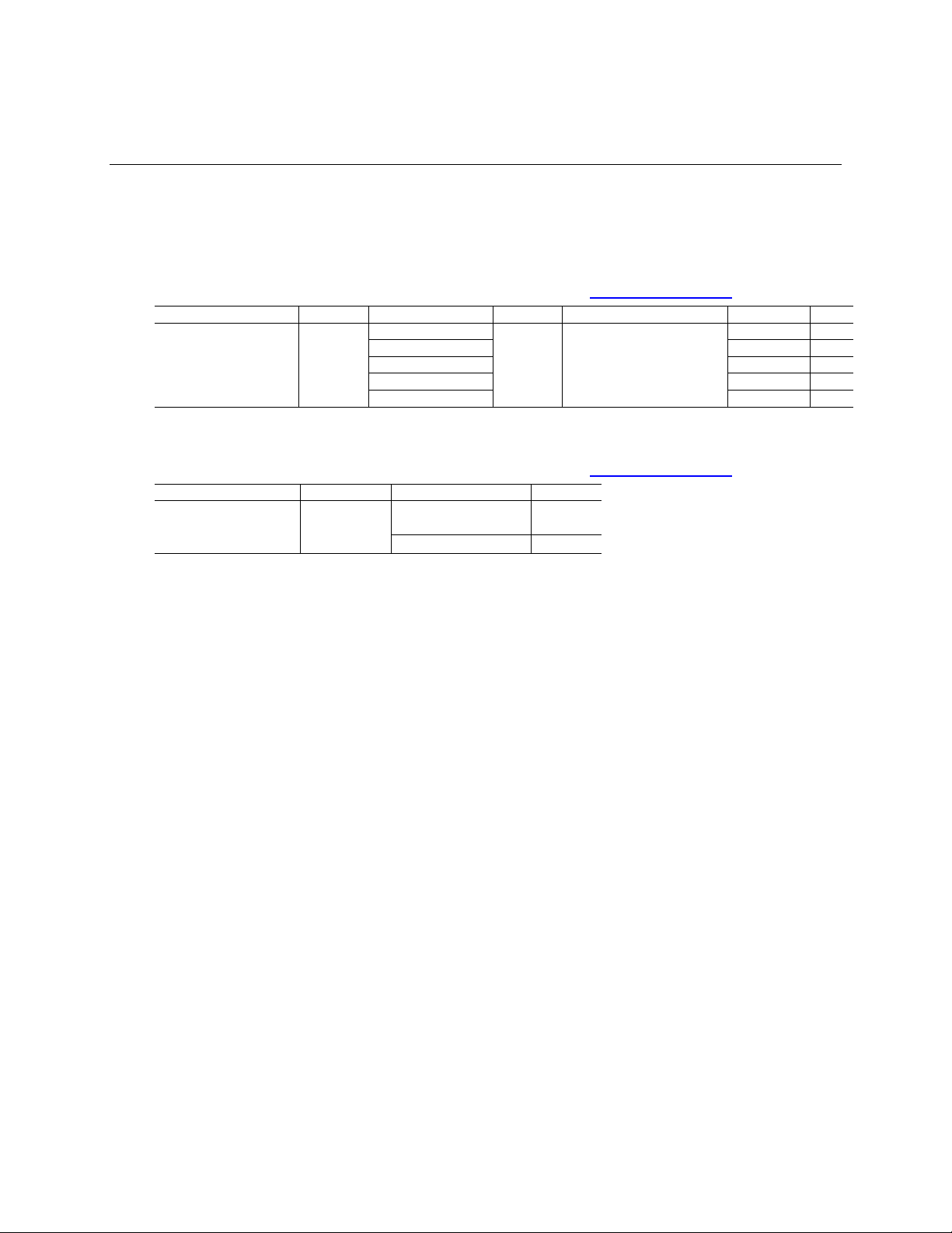
Production Identification Information
Intel® NUC Products NUC11PH{X} Identification Information
Product Name
Intel® NUC Board
NUC11PHKi7C
NUC11PHi7C
Specification Changes or Clarifications
The table below indicates the Specification Changes or Specification Clarifications that apply to
the Intel NUC Kit/Mini PC NUC11PH{X}.
Specification Changes or Clarifications
Date
Type of Change
Description of Changes or Clarifications
Errata
Current characterized errata, if any, are documented in a separate Specification Update. See
http://www.intel.com/content/www/us/en/nuc/overview.html for the latest documentation.
Online Support
To Find Information About…
Visit this World Wide Web site:
Intel NUC Kit/Mini PC NUC11PH{X}
http://www.intel.com/NUC
Intel NUC Kit/Mini PC Support
http://www.intel.com/NUCSupport
High level details for Intel NUC Kit/Mini PC
NUC11PH{X}
https://ark.intel.com
BIOS and driver updates
https://downloadcenter.intel.com
Tested memory
http://www.intel.com/NUCSupport
Integration information
http://www.intel.com/NUCSupport
Processor datasheet
https://ark.intel.com
Regulatory documentation
https://www.intel.com.tw/content/www/tw/zh/supp
ort/articles/000057855.html
Page 6

Table of Contents
1 Product Description .................................................................................................. 9
1.1 Overview ......................................................................................................................................................... 9
1.1.1 Summary of Mini PC SKUs .................................................................................................... 9
1.1.2 Summary of Kit SKUs .............................................................................................................. 9
1.1.3 Feature Summary .................................................................................................................. 10
2 Product Layout ........................................................................................................ 13
2.1 Board Layout .............................................................................................................................................. 13
2.1.1 Board Layout (TOP) ............................................................................................................... 13
2.1.2 Board Layout (Bottom) ........................................................................................................ 14
2.1.3 Front Panel ............................................................................................................................... 14
2.1.4 Back Panel ................................................................................................................................ 15
2.1.5 Block Diagram ......................................................................................................................... 16
3 Feature Descriptions .............................................................................................. 17
3.1 System Memory ........................................................................................................................................ 17
3.1.1 Intel® NUC Mini PC Memory Information ..................................................................... 17
3.2 Processor Graphics Subsystem .......................................................................................................... 17
3.2.1 General Power and Memory Guidance for Optimal Graphics Performance . 17
3.2.2 Intel® Iris Xe Graphics ........................................................................................................... 17
3.2.3 Intel® UHD Graphics for 11th Gen Intel Processors .................................................. 18
3.3 Integrated Audio ....................................................................................................................................... 18
3.4 SATA Interface ........................................................................................................................................... 18
3.5 Real-Time Clock Subsystem ................................................................................................................ 18
3.6 LAN Subsystem ......................................................................................................................................... 19
3.6.1 RJ-45 LAN Connector with Integrated LEDs .............................................................. 19
3.7 Hardware Management Subsystem ................................................................................................. 20
3.7.1 Fan Monitoring ........................................................................................................................ 20
3.7.2 System States and Power States .................................................................................... 20
4 Technical Reference ................................................ Error! Bookmark not defined.
4.1 Connectors and Headers....................................................................................................................... 22
4.1.1 Signal Tables for the Connectors and Headers ........................................................ 22
4.2 Mechanical Considerations .................................................................................................................. 28
4.2.1 Form Factor .............................................................................................................................. 28
4.3 Thermal Considerations ........................................................................................................................ 29
4.4 Reliability ..................................................................................................................................................... 30
4.5 Environmental ........................................................................................................................................... 30
Page 7

Contents
vii
5 Overview of BIOS Features ................................................................................... 32
5.1 Introduction ................................................................................................................................................ 32
5.2 Legacy USB Support ............................................................................................................................... 32
5.3 BIOS Updates ............................................................................................................................................. 32
5.3.1 BIOS Recovery ......................................................................................................................... 32
5.4 Boot Options .............................................................................................................................................. 33
5.4.1 Boot Device Selection During Post................................................................................. 33
5.4.2 Power Button Menu .............................................................................................................. 33
5.5 Hard Disk Drive Password Security Feature .................................................................................. 34
5.6 BIOS Security Features .......................................................................................................................... 35
5.7 BIOS Error Messages ............................................................................................................................... 36
Page 8

List of Figures
Figure 1. Major Board Components (Bottom) ................................................................................................. 13
Figure 2. Front Panel Connectors ........................................................................................................................ 14
Figure 3. Back Panel Connectors ......................................................................................................................... 15
Figure 4. Block Diagram ........................................................................................................................................... 16
Figure 5. LAN Connector LED Locations........................................................................................................... 19
Figure 6. Common IO Header ............................................................................................................................... 25
Figure 7. Location of the BIOS Security Jumper ........................................................................................... 26
Figure 8. System Dimensions ................................................................................................................................. 28
List of Tables
Table 1. Feature Summary ..................................................................................................................................... 10
Table 2. Additional Features .................................................................................................................................. 12
Table 3. Components Shown in Figure 1 .......................................................................................................... 13
Table 4. Components Shown in Figure 2 ............................................................................................................. 6
Table 5. Components Shown in Figure 3 ............................................................................................................. 7
Table 6. LAN Connector LED States .................................................................................................................... 11
Table 7. Systems States ........................................................................................................................................... 12
Table 8. Wake-up Devices and Events ............................................................................................................... 12
Table 9. SATA Combined Data/Power Header ............................................................................................... 15
Table 10. M.2 2280 Module (Mechanical Key M) Connector .................................................................... 15
Table 11. M.2 2280 Module (Mechanical Key E) Connector ..................................................................... 17
Table 12. Front Panel Header (2.0 mm Pitch) ................................................................................................. 17
Table 13. BIOS Security Jumper Settings ......................................................................................................... 17
Table 14. Fan Header Current Capability .......................................................................................................... 26
Table 15. Enviromental Specs ............................................................................................................................... 20
Table 16. Acceptable Drives/Media Type for BIOS Recovery................................................................... 25
Table 17. Power Buttons .......................................................................................................................................... 26
Table 18. Master Key and User Hard Disk Drive Password Functions .................................................. 27
Table 19. Supervisor and User Password Functions .................................................................................... 25
Table 20. Power Buttons .......................................................................................................................................... 26
Page 9
9
1 Product Description
1.1 Overview
1.1.1 Summary of Mini PC SKUs
Product Codes and MM#s for the SKUs below can be found at https://ark.intel.com.
Processor
GPU
AC Cord (C5)
RAM
Storage
OS
TPM
Intel® Core™ i71165G7
RTX2060
+ 6GB
GDDR6
US, EU, or No Cord
2 x 8 GB
512GB Optane H10
Win 10 Pro
WW
CN
Win 10 Pro
CN - - - - - -
- - -
1.1.2 Summary of Kit SKUs
Product Codes and MM#s for the SKUs below can be found at https://ark.intel.com.
Processor
GPU
AC Cord (C5)
TPM
Intel® Core™ i7-
1165G7
RTX2060 +
6GB GDDR6
US, EU, UK, IN, AU or
No Cord
WW
CN
CN
Page 10

1.1.3 Feature Summary
Table 1 summarizes the major features of Intel® NUC Mini PC, Kit and Board NUC11PH{X}.
Table 1. Feature Summary
Board Dimensions
8.22in by 5.37in (208.9mm by 136.4mm)
Chassis Dimensions
Chassis: 8.93in by 5.7in by 1.57in (227mm by 145mm x 40mm) (including feet)
Processor
Intel® NUC Mini PCs, and Kits NUC11PH{X} have a soldered-down 11th generation Intel®
Core™ processor with up to 28 W TDP
• Intel® Core™ i7-1165G7 processor, MM# 99A3D0
More information about Intel® processors can be found at https://ark.intel.com
Memory
Two 260-pin 1.2 V DDR4 SDRAM Small Outline Dual Inline Memory Module (SO-DIMM)
sockets
• Support for DDR4 1866/2133/2400/3200 MHz SO-DIMMs
• Support for 8 Gb and 16 Gb technology
• Support for up to 64 GB of system memory with two SO-DIMMs using 32 GB
memory modules
• Support for non-ECC memory
• Support for 1.2 V JEDEC memory only
Note: 2 Gb and 4 Gb memory technology (SDRAM Density) is not supported
More information about tested memory can be found at http://www.intel.com/NUCSupport
Graphics
• Integrated graphics support for processors Intel® Graphics Technology
• Two Type C Front and back panel connectors
• Discrete graphics support by Nvidia RTX 2060
• One Full Size High Definition Multimedia Interface* (HDMI*) Back panel
connectors
• One Mini DisplayPort* back panel connectors
• Two Type C Front and back panel connectors
Audio
Audio via digital display outputs
• The following audio technologies are supported by the HDMI interfaces 192kHz/16-
bit or 176. kHz/24-bit, 32 Channel
• When using an encoded format (such as DTS-HD MA or Dolby True HD) the board
supports a single 7.1 stream. When using an un-encoded format, the board supports
8 discrete, un-encoded channels per HDMI port simultaneously, for a total of 16
discrete/un-encoded channels.
More information about software and drivers can be found at
https://downloadcenter.intel.com
Storage
One M.2 PCIe Gen4 connector supporting M.2 22x80 (key type M) for NVMe only
One M.2 connector supporting M.2 22x42 (key type B) for SATA SSD, PCIe x1 or USB 3.2
expandability
Page 11

Technical Reference
11
Communication
Intel® Wi-Fi 6 AX201 (Gig+) M.2 2230 add-in card via M.2 2230 (key type E) connector
• 802.11ax, Dual Band, 2x2 Wi-Fi + Bluetooth v5.1
• Maximum transfer speed up to 2.4 Gbps
• Supports PCIe and USB
More information about Intel® wireless products can be found at https://ark.intel.com
To obtain drivers visit https://downloadcenter.intel.com
Gigabit (10/100/1000/2500 Mbps) LAN subsystem using the Intel® i255-LM Gigabit
Ethernet Controller
• PCIe 3.1 5GT/s support for x1 width (Lane)
• Single-port integrated multi-gigabit (up to 2.5G) – standard IEEE 802.3 Ethernet
interface for 2500BASE-T, 1000BASE-T, 100BASE-TX, 10BASE-TE connections (IEEE
802.3, 802.3u, 802.3bz, and 802.3ab)
• Supports Time Sensitive Networking (TSN) IEEE 802.1Qbu, 802.3br, 802.1Qbv,
802.1AS-REV, 802.1p,Q, and 802.1Qav
• Full wake up support
• Supports for packets up to 9.5 KB (Jumbo Frames)
• Support for two RJ45 ports with the Dual LAN chassis option
More information about Intel® Ethernet controllers can be found at https://ark.intel.com
To obtain drivers visit https://downloadcenter.intel.com
Thunderbolt™
2 x Thunderbolt™ ports (front and back panel)
• USB4 compliant
• 15W and18W port bus power
• Thunderbolt networking
• Protocol support:
PD Modes Supported: TBT3, USB4, USB3, DP-alt/MF
TBT3 Tx/Rx rates: 40G (2x 20.625), 20G (2x 10.3125)
PCI Express Tunnel: 32 Gbps
USB4 Tx/Rx rates: 40G (2x 20), 20G (2x 10)
USB3 Native: 10Gbps (1x10G)
USB3 Tunnel: 10Gbps
USB2: 480 Mpbs
DP1.4a, HBR3
DisplayPort Tunneling:
Port 2: 2 streams (~35 Gbps, Thunderbolt 4 certified)
Port 1: 1 stream (~17 Gbps, Thunderbolt 3 certified)
More information about the location of the Thunderbolt™ ports can be found in Section
2.1.4 later in this document
USB Ports and Headers
2 x USB 4 ports via Type C/Thunderbolt™ (Front and back panel)
6 x USB 3.2 Gen 2 ports (2 front panel and 4 back panel)
1 x USB 2.0 port (M.2 slot)
More information about the location of the USB ports and headers can be found in Section
2 later in this document
More information about the pinout of the USB ports and headers can be found in Section
4.1 later in this document
Power
AC Adapter
• ships with a 230W 19.5V adapter
Power Input
• 12V
DC
to 24V
DC
+/- 5% with DC transient voltage protection
More information about the estimated power budget can be found in Section Error! R
eference source not found. later in this document
Page 12

Operating
Temperatures
0-40C external ambient operating temperature
More information about environmental specifications can be found in Section 4.5 later in
this document
BIOS
Intel® BIOS resident in the Serial Peripheral Interface (SPI) Flash device
Support for Advanced Configuration and Power Interface (ACPI), Plug and Play, and System
Management BIOS (SMBIOS)
Operating System (Mini
PCs only)
Intel® NUC Mini PCs NUC11PH{X} can be purchased with Windows 10 Pro 64-bit
preinstalled
More information about available Intel® NUC Mini PCs NUC11PH{X} can be found in Section
1.1.1 Summary of Mini PC SKUs. For Product Codes and MM#s visit https://ark.intel.com
Hardware Monitor
Subsystem
Hardware monitoring subsystem including:
Voltage sense to detect out of range power supply voltages
Thermal sense to detect out of range thermal values
One processor fan header
Fan sense input used to monitor fan activity
Fan speed control
Table 2. Additional Features
Chassis Expandability
No Chassis Expansion available
HDMI CEC API
CEC commands are supported on all HDMI ports for display power on/off and the BIOS
provides an option to enable/disable the onboard CEC controls
Sustained Operation
Qualified for 24x7 sustained operation
Auto CMOS Reset
Delayed AC Start
There is a short delay after AC power is applied before unit is ready to power-up to protect
the system after AC loss.
Intel® Transparent
Supply Chain
System level visibility and traceability of hardware and firmware that assures platform
integrity throughout the compute lifecycle
More information about Intel® TSC is available on
https://www.intel.com/content/www/us/en/products/docs/servers/transparent-supplychain.html
Page 13

Technical Reference
13
2 Product Layout
2.1 Board Layout
2.1.1 Board Layout (TOP)
Figure 1 shows the location of the major components on the bottom of Intel® NUC Board
NUC11PH{X}.
Figure 1. Major Board Components (Top)
Table 3. Components Shown in Figure 1
Item from Figure 1
Description
A
Fan Connector
B
M.2 2280 Module Connector (Key Type B) (NVMe/SATA)
C
M.2 2280 Module Connector (Key Type M) (NVMe Only)
D
Fan Connector
E
BIOS Security Header
F
Common I/O Header
G
DDR4 SO-DIMM 1 Socket
Page 14

H
DDR4 SO-DIMM 0 Socket
I
AX201D Wifi Module
J
DMIC connector
K
CMOS Battery
L
RGB Header
2.1.2 Board Layout (Bottom)
No user configurable components on the bottom-side of Intel® NUC Board NUC11PH{X}.
2.1.3 Front Panel
Figure 2. Front Panel Connectors
Table 4. Components Shown in Figure 2
Item from Figure 2
Description
A
IR Sensor
B
SD Card Reader
C
DMICs
D
Thunderbolt USB-C
E
USB 3.2 gen 2
F
USB 3.2 gen 2 2A peak current support
G
Audio
H
Power Button
Page 15

Technical Reference
15
2.1.4 Back Panel
Figure 3. Back Panel Connectors
Table 5. Components Shown in Figure 3
Item from Figure 2
Description
A
Kensington Lock
B
Optical audio port
C
Ethernet
D
USB 3.2 gen 2
E
Thunderbolt USB-C
F
HDMI
G
Mini Display Port
H
Power Input
Page 16

2.1.5 Block Diagram
Figure 4. Block Diagram
Page 17

Technical Reference
17
3 Feature Descriptions
3.1 System Memory
Figure 1 illustrates the memory channel and SO-DIMM configuration.
3.1.1 Intel® NUC Mini PC Memory Information
Intel® NUC Mini PCs NUC11PH{X} can be purchased with 2 x 8 GB DDR4 3200 MHz SODIMMs
included. More information about available Intel® NUC Mini PCs NUC11PH{X} can be found in
Section 1.1.1 Summary of Mini PC SKUs. For Product Codes and MM#s visit https://ark.intel.com.
3.2 Processor Graphics Subsystem
Intel® NUC Boards NUC11PH{X} support Intel® Iris® Xe Graphics.
3.2.1 General Power and Memory Guidance for Optimal Graphics
Performance
Intel® NUC Boards NUC11PH{X} graphics performance is significantly impacted by power levels
and memory selection. For the best performance:
• Allow for higher system power level budgets
• Recommend DDR4-3200 128bit 2Rx8
o 128bit (Dual Channel) memory is better performing than 64bit (Single Channel)
memory
o A full list of tested memory modules are available on
https://compatibleproducts.intel.com
3.2.2 Intel® Iris Xe Graphics
Intel® Iris® Xe Graphics supports the following features:
• The HW decode is exposed by the graphics driver using the following APIs: Direct3D* 9 Video
API (DXVA2), Direct3D11 Video API, Intel Media SDK, MFT filters, Intel VA API
o Full HW accelerated video decoding for AVC/VC1/MPEG2/HEVC/VP9/JPEG/AV1
• The HW encode is exposed by the graphics driver using the following APIs: Intel Media SDK,
MFT filters
o Full HW accelerated video encoding for AVC/HEVC/VP9/JPEG
• Max HDMI resolution 4096x2304 at 60Hz
• Max DP resolution 7680x4320 at 60Hz
• Up to four simultaneous displays
• Four display pipes – supporting blending, color adjustments, scaling and dithering
• Direct 3D* 2015, Direct3D* 12
• OpenGL* 4.5
• Open CL* 2.1
• HDR (High Dynamic Range) support
Page 18

• HDCP (High-bandwidth Digital Content Protection) 2.2 and 1.4
3.2.3 Intel® UHD Graphics for 11
th
Gen Intel Processors
Intel® UHD Graphics for 11th Gen Intel Processors features the following:
• DirectX* 12.1 support
• OpenGL* 4.5 support
• Max HDMI resolution 4096x2304 at 60Hz
• Max DP resolution 7680x4320 at 60Hz
• OpenCL* 2.0 support
3.3 Integrated Audio
HDMI and DP interfaces can carry audio along with video. The processor supports three HD audio
streams over four digital ports simultaneously. The processor supports the following audio
formats over HDMI and DP:
• AC-3 Dolby* Digital
• Dolby* Digital Plus
• DTS-HD*
• LPCM, 192 kHz/24 bit, 6 channel
• Dolby* TrueHD, DTS-HD Master Audio*
Audio drivers are built into the Graphics driver and are available from Intel’s website.
For information about
Refer to
Obtaining NUC software and drivers
https://downloadcenter.intel.com/
3.4 SATA Interface
The board provides the following SATA interfaces:
• One SATA 6.0 Gb/s combined Data and Power connector (blue)
The PCH provides independent SATA ports with a theoretical maximum transfer rate of 6 Gb/s. A
point-to-point interface is used for host to device connections.
3.5 Real-Time Clock Subsystem
A coin-cell battery (CR2032) powers the real-time clock and CMOS memory. When the computer
is not plugged into a wall socket, the battery has an estimated life of three years. When the
computer is plugged in, the standby current from the power supply extends the life of the battery.
The clock is accurate to 13 minutes/year at 25 ºC with 3.3 VSB applied via the power supply 5 V
STBY rail.
NOTE
If the battery and AC power fail, date and time values will be reset and the user will be notified
during the POST.
Page 19

Technical Reference
19
When the voltage drops below a certain level, the BIOS Setup program settings stored in CMOS
RAM (for example, the date and time) might not be accurate. Replace the battery with an
equivalent one. Error! Reference source not found. on page Error! Bookmark not defined. shows
the location of the battery.
3.6 LAN Subsystem
3.6.1 RJ-45 LAN Connector with Integrated LEDs
Two LEDs are built into the RJ-45 LAN connector (shown in Figure 5).
Item
Description
A
Link LED (Green)
B
Data Rate LED (Green/Yellow)
Figure 5. LAN Connector LED Locations
Table 6 describes the LED states when the board is powered up and the LAN subsystem is
operating.
Table 6. LAN Connector LED States
LED
LED Color
LED State
Condition
Link
Green
Off
LAN link is not established
Solid
LAN link is established
Blinking
LAN activity is occurring
Data Rate
Green/Yellow
Off
10/100 Mb/s data rate is selected
Green
1000 Mb/s data rate is selected
Yellow
2500 Mb/s data rate is selected
Page 20

3.7 Hardware Management Subsystem
3.7.1 Fan Monitoring
Fan monitoring can be implemented using third-party software.
3.7.2 System States and Power States
Table 7 describes the ACPI states supported by the processor.
Table 7. Systems States
State
Description
G0/S0/C0
Full On: CPU operating. Individual devices may be shut to save power. The different
CPU operating levels are defined by Cx states.
GO/S0/Cx
Cx State: CPU manages C-states by itself and can be in lower power states.
G1
Suspend-To-RAM (STR): The system context is maintained in system DRAM, but
power is shut to non-critical circuits. Memory is retained and refreshes continue. All
external clocks are shut off; RTC clock and international oscillator clocks are still
toggling.
G1/S4
Suspend-To-Disk (STD): The context of the system is maintained on the disk. All
power is then shut to the system except to the logic required to resume. Externally
appears the same as S5 but may have different wake events.
G2/S5
Soft Off: System context not maintained. All power is shut except for the logic required
to restart. A full boot is required when waking.
G3
Mechanical Off: System context not maintained. All power shut except for the RTC. No
“Wake” events are possible because the system does not have any power. This state
occurs if the user removes the batteries, turns off a mechanical switch, or if the system
power supply is at a level that is insufficient to power the “waking” logic.
3.7.2.1 Wake-up Devices and Events
Table lists the devices or specific events that can wake the computer from specific states.
Table 8. Wake-up Devices and Events
Devices/events that wake up the
system…
…from this sleep
state
Comments
Power switch
S0iX, S4, S51
RTC alarm
S0iX, S4, S51
Option for monitor to remain in sleep
state
LAN
S0iX, S4, S5
1, 3
“S5 WOL after G3” is supported; monitor
to remain in sleep state
WIFI
S0iX, S4, S5
1, 3
Bluetooth
S0iX, S41
USB
S0iX, S4, S5
1, 2, 3
Wake S4, S5 controlled by BIOS option
(not after G3)
PCIe
S0iX, S41
Via WAKE; monitor to remain in sleep
state
Page 21

Technical Reference
21
HDMI CEC
S0iX, S4, S51
Wake S4, S5 controlled by BIOS option
Notes:
1. S4 implies operating system support only.
2. Will not wake from Deep S4/S5. USB S4/S5 Power is controlled by BIOS. USB S5 wake is controlled by BIOS. USB S4
wake is controlled by OS driver, not just BIOS option.
3. Windows Fast startup will block wake from LAN and USB from S5.
NOTE
The use of these wake-up events from an ACPI state requires an operating system that provides
full ACPI support. In addition, software, drivers, and peripherals must fully support ACPI wake
events.
Page 22

4 Technical Reference
4.1 Connectors and Headers
CAUTION
Only the following connectors and headers have overcurrent protection: back panel USB Type A
and Type C, front panel USB, internal USB headers, internal power header, and DC Vin jack.
All other connectors and headers are not overcurrent protected and should connect only to
devices inside the computer’s chassis, such as fans and internal peripherals. Do not use these
connectors or headers to power devices external to the computer’s chassis. A fault in the load
presented by the external devices could cause damage to the computer, the power cable, and the
external devices themselves.
Furthermore, improper connection of USB header single wire connectors may eventually overload
the overcurrent protection and cause damage to the board.
4.1.1 Signal Tables for the Connectors and Headers
Table 9. SATA Combined Data/Power Header
Pin
Signal Name
Pin
Signal Name
1
+5V (2A total for pins 1, 2, 3, 4 (0.5A per
pin))
2
+5V (2A total for pins 1, 2, 3, 4 (0.5A per
pin))
3
+5V (2A total for pins 1, 2, 3, 4 (0.5A per
pin))
4
+5V (2A total for pins 1, 2, 3, 4 (0.5A per
pin))
5
NC 6 NC 7 NC 8 DEVSLP
9
GND
10
GND
11
SATA_RX_P
12
SATA_RX_N
13
GND
14
SATA_TX_N
15
SATA_TX_P
16
GND
Connector is vertical 0.5mm contact pitch ZIF FPC/FFC with lock
Table 10. M.2 2280 Module (Mechanical Key M) Connector
Pin
Signal Name
Pin
Signal Name
74
3.3V (4A total for pins 74, 72, 70, 18, 16, 14, 12, 4, 2 (0.5A per pin))
75
GND
72
3.3V (4A total for pins 74, 72, 70, 18, 16, 14, 12, 4, 2 (0.5A per pin))
73
GND
70
3.3V (4A total for pins 74, 72, 70, 18, 16, 14, 12, 4, 2 (0.5A per pin))
71
GND
68
SUSCLK(32kHz) (O)(0/3.3V)
69
PEDET (NC-PCIe)
66
Connector Key
67
N/C
64
Connector Key
65
Connector Key
62
Connector Key
63
Connector Key
Page 23

Technical Reference
23
60
Connector Key
61
Connector Key
58
N/C
59
Connector Key
56
N/C
57
GND
54
PEWAKE# (I/O)(0/3.3V) or N/C
55
REFCLKP
52
CLKREQ# (I/O)(0/3.3V) or N/C
53
REFCLKN
50
PERST# (O)(0/3.3V) or N/C
51
GND
48
N/C
49
PETp0
46
N/C
47
PETn0
44
N/C
45
GND
42
N/C
43
PERp0
40
N/C
41
PERn0
38
DEVSLP (O)
39
GND
36
N/C
37
PETp1
34
N/C
35
PETn1
32
N/C
33
GND
30
N/C
31
PERp1
28
N/C
29
PERn1
26
N/C
27
GND
24
N/C
25
PETp2
22
N/C
23
PETn2
20
N/C
21
GND
18
3.3V (4A total for pins 74, 72, 70, 18, 16, 14, 12, 4, 2 (0.5A per pin))
19
PERp2
16
3.3V (4A total for pins 74, 72, 70, 18, 16, 14, 12, 4, 2 (0.5A per pin))
17
PERn2
14
3.3V (4A total for pins 74, 72, 70, 18, 16, 14, 12, 4, 2 (0.5A per pin))
15
GND
12
3.3V (4A total for pins 74, 72, 70, 18, 16, 14, 12, 4, 2 (0.5A per pin))
13
PETp3
10
DAS/DSS# (I/O)/LED1# (I)(0/3.3V)
11
PETn3
8
N/C 9 GND 6 N/C 7 PERp3
4
3.3V (4A total for pins 74, 72, 70, 18, 16, 14, 12, 4, 2 (0.5A per pin))
5
PERn3
2
3.3V (4A total for pins 74, 72, 70, 18, 16, 14, 12, 4, 2 (0.5A per pin))
3
GND
1
GND
Table 11. M.2 2230 Module (Mechanical Key E) Connector
Pin
Signal Name
Pin
Signal Name
74
3.3V (2A total for pins 74, 72, 4, 2 (0.5A per pin))
75
GND
72
3.3V (2A total for pins 74, 72, 4, 2 (0.5A per pin))
73
WT_CLKP
70
UIM_POWER_SRC/GPIO1/PEWAKE1#
71
WT_CLKN
68
CLKREQ1#
69
GND
66
PERST1#
67
WTD0P
64
REFCLK0
65
WTD0N
62
ALERT#/A4WP_IRQ# (I)(0/3.3)
63
GND
60
I2C CLK/A4WP_I2C_CLK (O)(0/3.3)
61
WT_D1P
Page 24

58
I2C DATA/A4WP_I2C_DATA (I/O)(0/3.3)
59
WT_D1N
56
W_DISABLE1# (O)(0/3.3V)
57
GND
54
W_DISABLE2# (O)(0/3.3V)
55
PEWAKE0# (I/O)(0/3.3V)
52
PERST0# (O)(0/3.3V)
53
CLKREQ0# (I/O)(0/3.3V)
50
SUSCLK(32kHz) (O)(0/3.3V)
51
GND
48
COEX1 (I/O)(0/1.8V)
49
REFCLKN0
46
COEX2(I/O)(0/1.8V)
47
REFCLKP0
44
COEX3(I/O)(0/1.8V)
45
GND
42
CLink_CLK (I/O)
43
PERn0
40
CLink_DATA (I/O)
41
PERp0
38
C-Link RESET* (I) (0/3.3V)
39
GND
36
UART RTS/BRI_DT (I) (0/1.8V)
37
PETn0
34
UART CTS (O) (0/1.8V)
35
PETp0
32
UART TXD/RGI_DT (I) (0/1.8V)
33
GND
30
Connector Key
31
Connector Key
28
Connector Key
29
Connector Key
26
Connector Key
27
Connector Key
24
Connector Key
25
Connector Key
22
UART RXD/BRI_RSP (O) (0/1.8V)
23
WGR_CLKP
20
UART WAKE# (O) (0/3.3V)
21
WGR_CLKN
18
GND/LNA_EN
19
GND
16
BT_LED (LED2#)
17
WGR_D0P
14
PCM_OUT/I2SSD_OUT/CLKREQ0
15
WGR_D0N
12
PCM_IN/I2SSD_IN
13
GND
10
PCM_SYNC/I2SWS/RF_RESET_B
11
WGR_D1P
8
PCM_CLK/I2SSCK
9
WGR_D1N
6
LED1#
7
GND
4
3.3V (2A total for pins 74, 72, 4, 2 (0.5A per pin))
5
USB_D-
2
3.3V (2A total for pins 74, 72, 4, 2 (0.5A per pin))
3
USB_D+
1
GND
4.1.1.1 Common IO Header (1.25 mm Pitch)
This section describes the functions of the front panel header. Table 12 lists the signal names of
the front panel header. Figure is a connection diagram for the front panel header.
Table 12. Front Panel Header (2.0 mm Pitch)
Pin
Description
Pin
Description
1
USB_VBUS
2
GND
3
USB1_N
4
USB2_P
5
USB1_P
6
USB2_N
7
GND 8 USB_VBUS
9
HDD_LED_P
10
PWR_LED_P
Page 25

Technical Reference
25
11
HDD_LED_N
12
PWR_LED_N
13
RST_N
14
PWR_BTN_N
15
GND
16
CEC
17
5V_STBY
18
VCC5
19
RSVD
20
GND
Figure 6. Common IO Header (1.25 mm Pitch)
4.1.1.2 BIOS Security Jumper
CAUTION
Do not move a jumper with the power on. Always turn off the power and unplug the power cord
from the computer before changing a jumper setting. Otherwise, the board could be damaged.
Figure shows the location of the BIOS Security Jumper. The 3-pin jumper determines the BIOS
Security program’s mode.
Page 26

Figure 7. Location of the BIOS Security Jumper
Table 13 describes the jumper settings for the three modes: normal, lockdown, and configuration.
Table 13. BIOS Security Jumper Settings
Function/Mode
Jumper Setting
Configuration
Normal
1-2
The BIOS uses current configuration information and passwords for
booting.
Lockdown
2-3
The BIOS uses current configuration information and passwords for
booting, except:
• All POST Hotkeys are suppressed (prompts are not displayed and
keys are not accepted. For example, F2 for Setup, F10 for the Boot
Menu).
• Power Button Menu is not available (see Section 5.4.2 Power Button
Menu).
BIOS updates are not available except for automatic Recovery due to
flash corruption.
Page 27

Technical Reference
27
Configuration
None
BIOS Recovery Update process if a matching *.bio file is found. Recovery
Update can be cancelled by pressing the Esc key.
If the Recovery Update was cancelled or a matching *.bio file was not
found, a Config Menu will be displayed. The Config Menu consists of the
following (followed by the Power Button Menu selections):
[1] Suppress this menu until the BIOS Security Jumper is
replaced.
[2] Clear BIOS User and Supervisor Passwords.
[3] Reset Intel® AMT to default factory settings.
[4] Clear Trusted Platform Module.
Warning: Data encrypted with the TPM will no longer be
accessible if the TPM is cleared.
[F2] Intel® Visual BIOS.
[F4] BIOS Recovery.
See Section 5.4.2 Power Button Menu
4.1.1.3 Fan Header Current Capability
Table 14 lists the current capability of the fan headers.
Table 14. Fan Header Current Capability
Fan Header
Maximum Available Current
Processor fan
1 A
4.1.1.4 Power Supply Connectors
The board has the following power supply connectors:
• External Power Supply – the board can be powered through a 12-24 V DC connector on the
back panel. The back-panel DC connector is compatible with a 5.5 mm/OD (outer diameter)
and 2.5 mm/ID (inner diameter) plug, where the inner contact is +12-24 V DC and the shell is
GND. The maximum current rating is 10 A.
NOTE
External power voltage, 12-24 (±5%) V DC, is dependent on the type of power brick
used. System power requirements will depend on actual system configurations chosen
by the integrator, as well as end user expansion preferences. It is the system integrator’s
responsibility to ensure an appropriate power budget for the system configuration is
properly assessed based on the system-level components chosen.
Page 28

4.2 Mechanical Considerations
4.2.1 Form Factor
Figure 8 illustrates the mechanical form factor for the system. Dimensions are given in inches
[millimeters]. The outer dimensions are 8.93in by 5.7in by 1.57in [227 millimeters by
145 millimeters by 40 millimeters].
Figure 8. System Dimensions
Page 29

Technical Reference
29
4.3 Thermal Considerations
CAUTION
Failure to ensure appropriate airflow may result in reduced performance of both the processor
and/or voltage regulator or, in some instances, damage to the board.
All responsibility for determining the adequacy of any thermal or system design remains solely
with the system integrator. Intel makes no warranties or representations that merely following the
instructions presented in this document will result in a system with adequate thermal
performance.
CAUTION
Ensure that the ambient temperature does not exceed the board’s maximum operating
temperature. Failure to do so could cause components to exceed their maximum case temperature
and malfunction. For information about the maximum operating temperature, see the
environmental specifications in Section 4.5.
CAUTION
Ensure that proper airflow is maintained in the processor voltage regulator circuit. Failure to do
so may result in shorter than expected product lifetime.
Page 30

4.4 Reliability
The demonstrated Mean Time Between Failures (MTBF) is done through 24/7 testing. Full Intel®
NUC systems in chassis with memory, SSD or HDD, and fans are ran at 100% on time for 90 days
continuously while running system wide stress inducing software in a 40 °C ambient air
temperature chamber. The demonstrated MTBF for Intel NUC Board NUC11PH{X} is >50,000
hours.
4.5 Environmental
Table 16 lists the environmental specifications for the board.
CAUTION
If the external ambient temperature exceeds 40 oC, further thermal testing is required to ensure
components do not exceed their maximum operating temperature.
Table 16. Environmental Specifications
Parameter
Specification
Temperature
Sustained Storage Limits (i.e.
warehouse)
-20 C to +40 C
Short Duration Limits (i.e. shipping)
-40 °C to +60 °C
Ambient Operating – NUC Kit*
0 C to +40 C
Ambient Operating – NUC Board*
0 C to +40 C
* Processor performance may automatically decrease when the system
operates in the top 5 °C of the ambient operating temperature ranges above.
Shock (Board)
Unpackaged
50 g trapezoidal waveform
Velocity change of 170 inches/s²
Packaged
Free fall package drop machine set to the height determined by the weight
of the package.
Product
Weight
(pounds)
Non-palletized Product
drop height (inches)
Palletized drop heights (single
product) (inches)
<20
36
N/A
21-40
30
N/A 41-80
24
N/A 81-100
18
12 100-120
12
9
Vibration (System)
Unpackaged
Random profile 5 Hz to 40 Hz @ 0.015 g^2/Hz to 500 Hz @ 0.00015
g^2/Hz(slope down)
Page 31

Technical Reference
31
Input acceleration is 1.09 gRMS
Packaged
Random profile 5 Hz to 40 Hz @ 0.015 g^2/Hz to 500 Hz @ 0.00015
g^2/Hz(slope down)
Input acceleration is 1.09 gRMS
Note: The operating temperature of the board may be determined by measuring the air temperature from the junction of
the heatsink fins and fan, next to the attachment screw, in a closed chassis, while the system is in operation.
Note: Before attempting to operate this board, the overall temperature of the board must be above the minimum
operating temperature specified. It is recommended that the board temperature be at least room temperature
before attempting to power on the board. The operating and non-operating environment must avoid condensing
humidity.
Page 32

5 Overview of BIOS Features
5.1 Introduction
The board uses an Intel AMI BIOS core that is stored in the Serial Peripheral Interface Flash
Memory (SPI Flash) and can be updated through multiple methods (see Section 5.3). The SPI
Flash contains the BIOS Setup program, POST, the PCI auto-configuration utility, LAN EEPROM
information, and Plug and Play support. The SPI Flash includes a 32 MB flash memory device.
The BIOS Setup program can be used to view and change the identification information and the
BIOS settings for the system. The BIOS Setup program is accessed by pressing <F2> after the
POST memory test beings and before the operating system boots.
5.2 Legacy USB Support
Legacy USB support enables the USB devices to be used even when the operating system’s USB
drivers are not yet available. Legacy USB support is used to access the BIOS setup program and to
install an operating system that supports USB. By default, Legacy USB support is set to Enabled.
To install an operating system that supports USB, verify that Legacy USB support in the BIOS
Setup program is set to Enabled and follow the operating system’s installation instructions.
5.3 BIOS Updates
The BIOS can be updated using one of the following methods:
1. Express BIOS (Windows-based) Update
2. F7 Update
3. Power Button Menu Update
4. iFlash Update
5. UEFI Shell Update
More information and instructions on how to use each of these methods can be found at BIOS
Update and Recovery Instructions. All BIOS update files for Intel NUCs are available on Download
Center.
5.3.1 BIOS Recovery
It is unlikely that anything will interrupt a BIOS update; however, if an interruption occurs the
BIOS could be unstable. Table 16 lists the drives and media types that can be used for BIOS
recovery. The BIOS recovery media does not need to be made bootable. More information about
BIOS recovery methods and instructions can be found at BIOS Update and Recovery Instructions.
Table 16. Acceptable Drives/Media Type for BIOS Recovery
Media Type
(Note)
Can be used for BIOS recovery?
Hard disk drive (connected to USB)
Yes
USB flash drive
Yes
NVME SSD (M.2 interface)
Yes
Page 33

Technical Reference
33
NOTE Supported file systems for BIOS recovery: NTFS (sparse, compressed, or encrypted
files are not supported), FAT32, EXT
5.4 Boot Options
In the BIOS Setup program, the user can choose to boot from a hard drive, removeable driver, or
the network. The default setting is for the hard drive to be the first boot device, the removeable
drive second, and the network third.
NOTE The network can be selected as a boot device. This selection allows booting from the
onboard LAN or a network add-in card with a remote boot ROM installed. Pressing the <F12> key
during POST automatically forces booting from the LAN. To use this key during POST, the User
Access Level in the BIOS Setup program’s Security menu must be set to Full.
5.4.1 Boot Device Selection During Post
Pressing the <F10> key during POST causes a boot device menu to be displayed. The menu
displays the list of available boot devices.
5.4.2 Power Button Menu
As an alternative to Configuration Mode or normal POST hotkeys, the user can use the power
button to access a menu with BIOS and boot options. The Power Button Menu is accessible via
the following sequence:
1. System is in S4/S5 (not G3)
2. User pushes the power button and holds it down for 3 seconds
3. The Front Panel Power Button LED will be on for the first 3 seconds. After 3 seconds, the LED
will begin to blink in the following pattern: 0.25 seconds off, 0.25 seconds on, 0.25 seconds
off to signal the user to release the power button
4. User releases the power button before the 4-second shutdown override
If this boot path is taken, the BIOS will use default settings, ignoring settings in VPD where
possible. At the point where Setup Entry/Boot would be in the normal boot path, the BIOS
will display the following prompt and wait for a keystroke:
If an unrecognized key is hit, then the BIOS will do nothing and wait for another keystroke. If
one of the listed hotkeys is hit, the BIOS will follow the indicated boot path. Password
requirements must still be honored.
Table 17. Power Button Menu Options
Keystroke
Option
Description
[ESC]
Normal Boot
[F2]
BIOS Setup Menu
[F3]
Disable Fast Boot
Note: Will only be displayed if at least one Fast Boot optimization is
enabled.
If Disable Fast Boot is selected, the BIOS will disable all Fast Boot
optimizations and reset the system.
Page 34

[F4]
BIOS Recovery
The BIOS will search for a matching .CAP file from the \EFI\Intel folder in
the supported media with the supported file system. If a matching
recovery capsule is found, the BIOS will display the following:
BIOS will Recover to <BIOSID> in 20 seconds.
[ESC] Cancel Recovery
Recovery will proceed if not cancelled via the ESC key within 20 seconds.
The BIOS shall display the recovery progress. If a BIOS .CAP file was not
detected (or the BIOS Recovery was cancelled) then the BIOS will reset
the system and continue normally to POST.
[F5]
Restore BIOS Settings
The BIOS will restore the current setup settings and the current defaults
to the build time defaults in the case of a boot issue caused by setup
variable changes.
[F7]
Update BIOS
BIOS Update during the BDS phrase. The BIOS will update independent of
any OS loading and provides a menu UI accessible during boot up. This is
not a recovery tool and will not overwrite a corrupt BIOS or ME firmware.
[F9]
Remote Assistance
Note: Will only be displayed if Remote Assistance is supported.
[F10]
Enter Boot Menu
[F12]
Network Boot
5.5 Hard Disk Drive Password Security Feature
The Hard Disk Drive Password Security feature blocks ready and write access to the hard disk
drive until the correct password is given. Hard disk drive passwords are set in BIOS Setup and are
prompted for BIOS POST. For convenient support for resuming from S3, the system BIOS will
automatically unlock drives on resume from S3. Valid password characters are A-Z, a-z, and 0-9.
Passwords may be up to 32 characters in length.
The User hard disk drive password, when set, will be required on each power cycle until the
Master Key or User hard disk drive password is submitted.
The Master Key hard disk drive password, when set, will not lock the drive. The Master Key hard
disk drive password exists as an unlock override if the User hard disk drive password is forgotten.
Only the User hard disk drive password, when set, will cause a hard disk to be locked on a system
power cycle. Table show the effects of setting the hard disk drive passwords.
Table 18. Master Key and User Hard Disk Drive Password Functions
Password Set
Password During Boot
Neither
None
Master only
None
User only
User only
Master and User Set
User
During every POST, if a User hard disk drive password is set, POST execution will pause with the
following prompt to force the User to enter the Master Key or the User hard disk drive password:
“Enter Hard Disk Drive Password:”
Upon successful entry of the Master Key or User hard disk drive password, the system will continue
with normal POST.
Page 35

Technical Reference
35
If the hard disk drive password is not correctly entered, the system will go back to the above
prompt. The User will have three attempts to correctly enter the hard disk drive password. After
the third unsuccessful attempt, the system will halt with the following message:
“Hard Disk Drive Password Entry Error”
A manual power cycle will be required to resume system operation.
NOTE As implemented on the Intel NUC11PH{X} board, the hard disk drive password security
feature is only supported on the SATA Port 0 (M.2) or the SATA port 1 (onboard SATA connector).
5.6 BIOS Security Features
The BIOS includes security features that restrict access to the BIOS Setup program and who can
boot the computer. A Supervisor and User password can be set for the BIOS Setup program and
for botting the computer, with the following restrictions:
• The Supervisor password gives unrestricted access to view and change all the Setup
options in the BIOS Setup program. This is Supervisor Mode.
• The User password gives restricted access to view and change Setup options in the BIOS
Setup program. This is User Mode.
• If only the Supervisor password is set, pressing the <Enter> key at the password prompt of
the BIOS Setup program allows the user restricted access to Setup.
• If both the Supervisor and User passwords are set, users can enter either the Supervisor or
User password to access Setup. Users have access to Setup regardless to which password
is used.
• Setting the User password restricts who can boot the computer. The password prompt
will be displayed before the computer boots. If only the Supervisor password is set, the
computer boots without asking for a password. If both passwords are set, the user can
enter either password to boot the computer.
• For enhanced security, use different passwords for the Supervisor and User passwords.
• Valid password characters are A-Z, a-z, 0-9, and special characters. Passwords may be up
to 20 characters in length.
• To clear a set password, enter a blank password after entering the existing password.
Table shows the effects of setting the Supervisor password and User password. This table is for
reference only and is not displayed on the screen.
Table 19. Supervisor and User Password Functions
Password Set
Supervisor Mode
User Mode
Setup Options
Password to
Enter Setup
Password
During Boot
Neither
Any user can
change all options
Any user can change
all options
None
None
None
Supervisor only
Can change all
options
Can change a limited
number of options
Supervisor Password
Supervisor
None
User only
N/A
Can change all
options
Enter Password
Clear User Password
User
User
Supervisor and
User set
Can change all
options
Can change a limited
number of options
Supervisor Password
Enter Password
Supervisor or
User
Supervisor or
User
Page 36

5.7 BIOS Error Messages
Table lists the error messages and provides a brief description of each.
Table 20. BIOS Error Messages
Error Message
Explanation
CMOS Battery Failure
The battery may be losing power. Replace the battery soon.
CMOS Checksum Error
The CMOS checksum is incorrect. CMOS memory may have been corrupted. Run Setup to
reset values.
Memory Size Decreased
Memory size has decreased since the last boot. If no memory was removed, then the
memory may be bad.
CMOS Timer Not Set
The battery may be losing power. Replace the battery soon.
Processor Thermal Trip
Processor overheated.
Auto RTC Reset
The system triggers RTC clear to recover the system back to the normal condition from
consecutive boot failure.
 Loading...