

Page 1

Quick UserQuick User
Quick User
Quick UserQuick User
Quick UserQuick User
Quick User
Quick UserQuick User
GuideGuide
Guide
GuideGuide
GuideGuide
Guide
GuideGuide
’s’s
’s
’s’s
’s’s
’s
’s’s
Intel Intel
Intel
Intel Intel
for Intel Socket 478 processorfor Intel Socket 478 processor
for Intel Socket 478 processor
for Intel Socket 478 processorfor Intel Socket 478 processor
TRADEMARK
All products and company names are trademarks or registered
trademarks of their respective holders.
These specifications are subject to change without notice.
i848Pi848P
i848P
i848Pi848P
Manual Revision 1.0
November 05, 2004
mainboard mainboard
mainboard
mainboard mainboard
60000014PLI10
Page 2

English
DISCLAIMER OF WARRANTIES:
THERE ARE NO WARRANTIES WHICH EXTEND BEYOND THE
DESCRIPTION ON THE FACE OF THE MANUFACTURER LIMITED
WARRANTY. THE MANUFACTURER EXPRESSLY EXCLUDES ALL
OTHER WARRANTIES, EXPRESS OR IMPLIED, REGARDING ITS
PRODUCTS; INCLUDING ANY IMPLIED WARRANTIES OF
MERCHANTABILITY, FITNESS FOR A PARTICULAR PURPOSE OR
NONINFRINGEMENT. THIS DISCLAIMER OF WARRANTIES SHALL
APPLY TO THE EXTENT ALLOWED UNDER LOCAL LAWS IN THE
COUNTRY PURCHASED IN WHICH LOCAL LAWS DO NOT ALLOW
OR LIMIT THE EXCLUSION OF THE IMPLIED WARRANTIES.
2
Page 3
1. Specification
Processor Support
Socket 478 Intel® Pentium® 4 processors up to 3.4GHz with 533/800MHz
front Side Bus
Socket 478 Intel
533MHz front Side Bus
Supports Hyper-Threading Technology
Chipset
Intel 848P Chipset (848P + ICH5)
Main Memory
Two 184-pin DDR DIMM sockets for PC2100/PC2700/PC3200 (DDR266/333/
400) DIMMs
Supports up to 2GB memory size
BIOS
Flash EEPROM with Award BIOS
- ACPI v2.0 compliant
- SMBIOS (System Management BIOS) v2.2 compliant
LAN
Integrates 10/100Mps Fast Ethernet controller with onboard Realtek RTL8100C
LAN Chipset
®
Celeron®and 3xx series processors up to 3.2GHz with 400/
English
Legacy IO Support
Winbond W83627HF LPC IO controller with floppy, printer, serial and CIR/SIR
interface
Audio
Six channel audio with analog and digital output using Realtek ALC655 AC’97 CODEC
- AC’97 v2.3 compliant
- Supports CD-In, Aux-In and S/PDIF-in/out interface
- Supports Line-out and Mic-In for front panel
- Supports automatic “jack-sensing”
- Rear panel audio jacks configuration:
roloCkcaJoiduA
eulBthgiLni-eniLtuo-oeretsraeR
emiLtuo-eniLtuo-oeretstnorF
kniPni-ciMrefoowbuS&retneC
lennahc2 lennahc6
3
Page 4
Expansion Slots
One AGP v3.0 compliant slot supporting 1.5v 8X AGP card
Five PCI v2.2 compliant slots
English
One CNR slot
Other Features
Magic Health – a BIOS H/W monitoring utility for voltage, temperature and fan-
speed sensing displayed during POST
EZ Boot – Simply press “ESC” to select your bootable device. No more hassle to
search the BIOS menu, change and re-start
Supports exclusive KBPO (Keyboard Power On) function
Form Factor
305mm x 205 mm ATX size
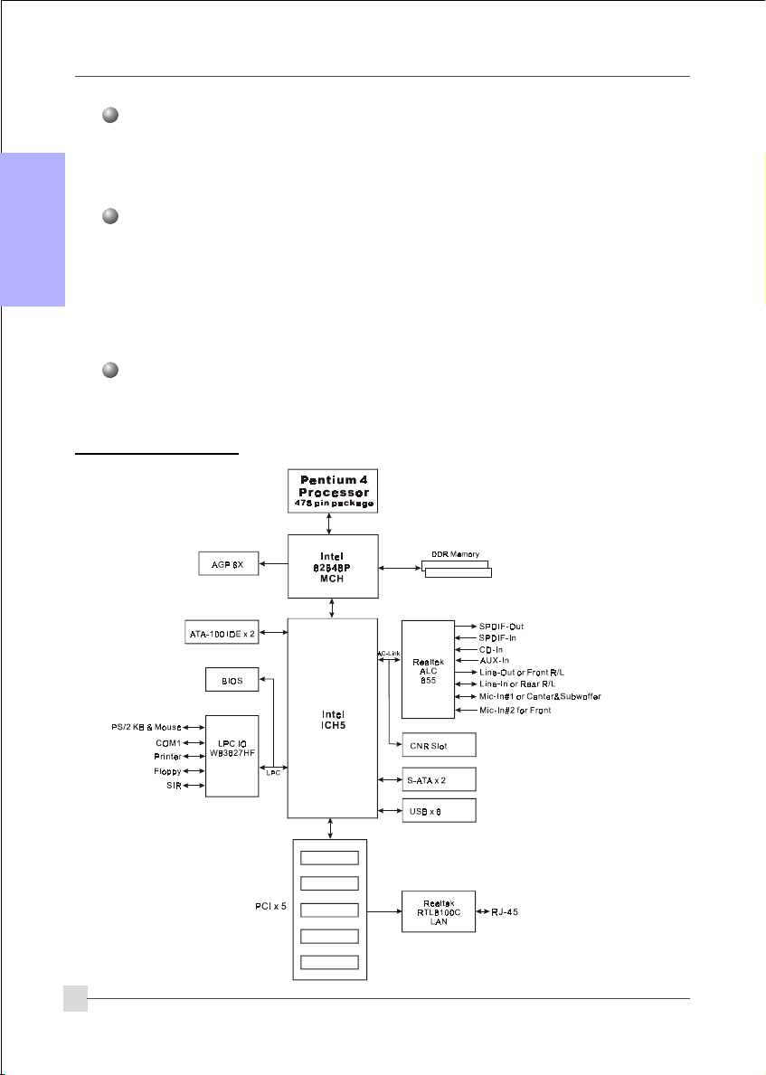
1.2 Block Diagram
with Bus Master support
4
Page 5
2. Setting up the mainbaord
Before assembling the mainboard into the PC case we recommend you to perform.
1. CPU Installation
2. DDR Memory Insertion
After the mainboard is fitted into the case, you may
3. Install Add-on VGA or PCI cards
4. Connect the internal cables and wires
5. Connect your external peripherals to the rear I/O port
3. Installation
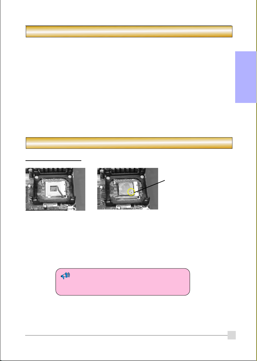
3.1 CPU Installation
Pin1
English
Step 1
Open the socket by raising
the actuation lever.
The CPU is keyed to prevent incorrect insertion, do not
force the CPU into the socket. If it does not go in easily,
check for mis-orientation.
Step 2
a) Align pin 1 on the CPU with pin 1 on the CPU socket as
shown above. Insert the CPU and make sure it is fully
inserted into the socket.
b) Close the socket by lowering and locking the actuation lever.
5
Page 6
English
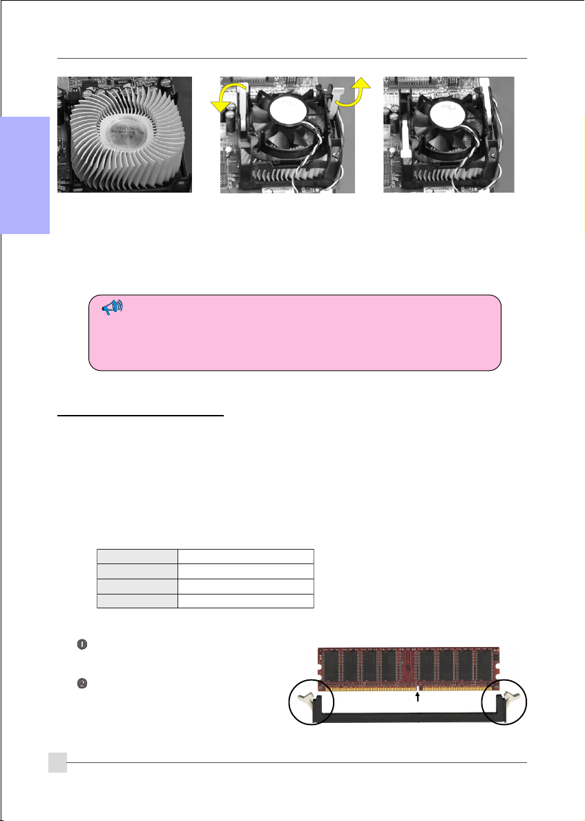
Step 3
Apply thermal compound
to the top of the CPU
surface and install the
heatsink as shown.
• Installing without a cooling fan will cause CPU overheat and damage the CPU.
• Apply heatsink thermal compound/paste to the CPU.
• Do not install a CPU over 50 times to avoid bending the pins and damaging the CPU.
Step 4
Install the cooling fan
assembly. Press the two
clips in the direction shown
above to secure its postion.
Step 5
Plug the cooling fan power
into the mainboard’s CPU fan
connector. The installation is
complete.
3.2 DDR Memory Insertion
The mainboard accommodates two PC2100/PC2700/PC3200 184-pin DIMMs (Dual In-line
Memory Modules):
• Supports up to 2.0GB of 266/333/400MHz DDR SDRAM.
• Supports unbuffered non-ECC DIMMs.
• DDR SDRAM supports 64, 128, 256, 512MB and 1GB DIMM modules.
• Supports DRAM configurations defined in the JEDEC DDR DIMM specification.
BSFUPCdetroppusyromeM
zHM004662RDD
zHM335333RDD/662RDD
zHM008004RDD/)zHM023(333RDD
* With DDR333, adaptive synchronization
aligns to the closest FSB to memory clock
ratio, setting the memory channel to 320MHz.
To install, align the notch on the
DIMM module with the connector.
Press straight down as shown in the
figure until the white clips close and
the module fits tightly into the
DIMM socket.
6
Notch
Page 7

3.3 VGA and PCI card installation
To install a VGA card into the AGP slot or a PCI expansion card:
1. Remove the bracket (on the PC case) for the slot you intend to use.
2. Firmly press down the card into the slot until it is completely seated. For an AGP
card ensure the AGP slot clicker is locked as shown in the picture below.
3. Secure the card's bracket to the PC case with a screw.
The AGP slot supports only newer VGA cards with 1.5V specifications.
English
7
Page 8

3.4 Rear IO Port
English
PS/2
Mouse
PS/2
Keyboard
3.5 Internal Connectors
4
Parallel Port
COM1
RJ-45
LAN
USB2.0 ports
Line-in/Rear out (Light blue)
Line-out/Front out (Lime)
Mic-in/Center&Subwoofer (Pink)
1
3
5
6
7
8 9
8
10
11
2
1
Page 9
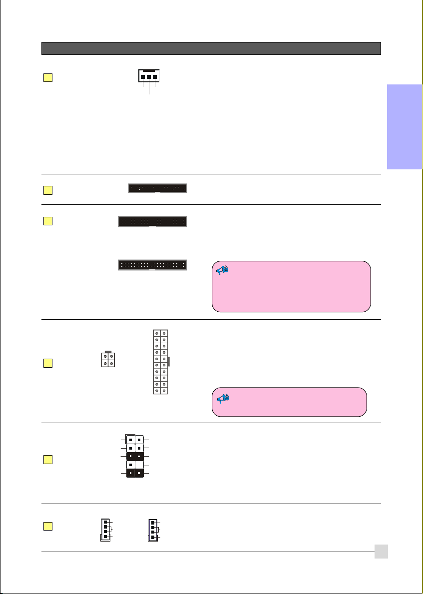
Connectors Figure Discriptions
JCPU_FAN
1
JPWR_FAN
JSYS_FAN
FDD
2
IDE1
3
Primary IDE
IDE2
Secondary IDE
PW1
4
PW12
CPU / Power / Chasis Fan Power Connectors
JCPU_FAN: The CPU must be kept cool by
Ground
+12V
Sense
using a heatsink with fan assembly.
JPWR_FAN: Use this connector if you are
installing an additional fan in the unit.
JSYS_FAN: The chassis fan will provide adequate
English
airflow throughout the chassis to
prevent overheating the CPU.
Floppy Drive Connector
1
Primary/Secondary IDE Connector
1
Connects to the IDE device, i.e. HDD and CD-
ROM device.
1
10
20
4
3
+12V+12V
GroundGround
2
1
11
1
PW1: 20-pin ATX Power Connector
+5V+12V
+5V5VSB
-5VPW-OK
PW12: 4-pin ATX12V Power Connector
GroundGround
Ground+5V
The plugs of the power cables are designed to fit
GroundGround
PS-ON+5V
in only one orientation.
GroundGround
-12V3.3V
3.3V3.3V
When using two IDE drives on the same
connector, one must be set to Master
mode and the other to Slave mode.
Refer to your disk drive user’s manual
for details.
The PW1 and PW12 Power Connector
must be used simultaneously.
5
6
CFPA
CD-IN
AUX-IN
MIC_In
Front Line-out-R
Front Line-out-L
CD_IN_Right
CD_Reference
CD_IN_Left
1
2
1
GND
9
+5V
Rear Line-out-FR
Key
Rear Line-out-FL
10
NC
CFPA: Front Panel Audio Connector
This connector is used only if the speaker and
microphone needs to be plugged at the front of
the PC case. Otherwise, leave the jumpers at the
default position.
CD-IN/AUX-IN: CD Audio-in connectors
These connectors are used to receive audio form a
CD-ROM drive, TV tuner or MPEG card.
9
1
AUX_IN_Right
GND
AUX_IN_Left
Page 10

7
English
8
Connectors Figure Discriptions
SPDIF_IN
SPDIF
5
6
GND
VCC
NC
SPDIF_OUT
1
2
SPDIF: Sony/Philips Digital InterFace connector
CUSB3/CUSB4: Four USB2.0 header
CUSB3
CUSB4
This mainboard includes 4 additional onboard
USB ports.
To use these additional USB ports, a USB bracket
is required. Please contact your retailer for details.
9
10
CFP
CIR
CSPK
SATA1
SATA2
CFP: Case Front Panel Connector
HD_LED
This LED indicates hard drive activity.
PWR_LED
Connects to the power indicator on the PC case.
RST
Connects to the RESET switch on the PC case.
PW_ON
Connects to the Power button on the PC case, to
turn on the system. To turn off the system,
press the power button for 4 seconds.
CIR: IR connector
For connection to an IrDA receiver unit.
CSPK: Speaker
Connects to the case’s speaker for PC beeps.
1
GND
GND
A+
B+
A-B-
GND
SATA1 / SATA2: Two Serial ATA Connectors
These connectors enable you to connect Serial
ATA devices that conform to the Serial ATA
specification.
10
Page 11

Connectors Figure Discriptions
11
JCMOS
1
Settings:
1-2: Normal (Default)
2-3: Clear CMOS
JCMOS: Clear CMOS data Jumper
This resets the BIOS CMOS data back to the
factory default values. Recommend to leave at
Normal (default) postion.
4. BIOS
BIOS Setup
When you start up the computer for the first time you need to enter the BIOS CMOS Setup
Utility. Power on the computer and press <Del> key during POST (Power On Self Test).
The BIOS CMOS SETUP UTILITY opens as shown below:
English
< CMOS Setup Utility>
Select and enter "Load Optimized Defaults" page. This page loads the factory settings for
optimal system performance. Follow the simple on-screen instructions to complete this
procedure. Press "ESC" to exit and select "Save & Exit Setup" to continue to boot.
Note : For more information regarding BIOS settings refer to the complete manual
in the bundled CD.
11
Page 12

5. Driver Installation
Once the operating system has been installed, you need to install the drivers for the mainboard.
English
Method 1
Method 2
Auto Installation
Selective Installation
Insert the bundled CD into the CD-ROM and the main menu screen will appear. The main
menu displays links to the supported drivers, utilities and software.
Method 1
This item installs all drivers automatically.
Method 2
This item allows you to install the drivers selectively.
Step 1 : Click “INTEL CHIPSET INF FILES” to install chipset driver.
Step 2 : Click “AC’97 AUDIO DRIVER” to install audio driver.
Step 3 : Click “REALTEK LAN DRIVER” to install LAN driver.
Step 4 : Click “USB V2.0 DRIVER” to launch a README.HTM file on how to
install USB2.0 driver for Windows 2000/XP.
12
Page 13

6. Others
Hyper-Threading
To enable the Hyper-Threading Technology function on your computer system
requires ALL of the following platform components:
)CPU: An Intel
)Chipset: An Intel® Chipset that supports HT Technology.
)BIOS: A BIOS that supports HT Technology and has it enabled.
)OS: An operating system that supports HT Technology.
Performance will vary depending on the specific hardware and software you use. See
<http://www.intel.com/info/hyperthreading> for information including details on
which processor support HT Technology.
®
Pentium® 4 Processor with HT Technology.
English
13
Page 14

7. Update BIOS
Download the xxxxx.EXE file corresponding to your model from our website to an empty
directory on your hard disk or floppy. Run the downloaded xxxxx.EXE file and it will self
extract. Copy these extracted files to a bootable floppy disk.
English
Note: The floppy disk should contain NO device drivers or other programs.
1. Type “A:\AWDFLASH and press <Enter> Key.
2. You will see the following setup screen.
3. Please key in the xxxxx.bin BIOS file
name.
4. If you want to save the previous BIOS
data to the diskette, please key in [Y],
otherwise please key in [N].
XXXX
5. Key in File Name to save previous BIOS
to file.
XXXX
XXXXX
xxxxx.bin
xxxxx.bin
7. The BIOS update is finished.
XXXX
XXXXX
xxxxx.bin
XXXX
XXXXX
xxxxx.bin
6. To confirm and proceed, please key in
[Y] to start the programming.
XXXX
XXXXX
xxxxx.bin
xxxxx.bin
14
F1 : Reset
F10 : Exit
 Loading...