

Page 1

REVISION 2.21
OCTOBER 2016
Intel® Server Chassis H2000G
Product Family
Technical Product Specification
A document providing an overview of product features, functions,
architecture, and support specifications
INTEL® SERVER PRODUCTS AND SOLUTIONS
Page 2

Revision History Intel® Server Chassis H2000G Product Family TPS
ii
Date
Revision
Number
Modifications
August, 2014
1.20
1st External Public Release
November, 2014
1.30
Added S2600TP and HNS2600TP
Updated the package dimensions in the Chassis Feature Set table
December, 2014
1.40
Added Appendix C System Configuration Table for Thermal Compatibility
February, 2015
1.41
Updated the System Environmental Limits Summary table and the
specification data for the AC Power Supply Unit table
August, 2015
1.50
Added Intel® Server Chassis H2224XXKR2
November, 2015
1.51
Corrected some information
April, 2016
1.60
Added Intel® Server Chassis H2224XXLR2
Added FXX2130PCRPS
May, 2016
2.0
Applied new format version definition
May, 2016
2.10
Added CFM specification for H2224XXKR2 and H2224XXLR2
June, 2016
2.20
Added Intel® Server Chassis H2312XXLR2 and H2216XXLR2
Added S7200AP references
October, 2016
2.21
Added Intel® SATA SSD support for H2224XXKR2 and H2224XXLR2
Typographical corrections
Revision History
Revision 2.21
Page 3

Intel® Server Chassis H2000G Product Family TPS Disclaimers
iii
Disclaimers
Information in this document is provided in connection with Intel® products. No license, express or implied, by
estoppel or otherwise, to any intellectual property rights is granted by this document. Except as provided in Intel's
Terms and Conditions of Sale for such products, Intel assumes no liability whatsoever, and Intel disclaims any
express or implied warranty, relating to sale and/or use of Intel products including liability or warranties relating to
fitness for a particular purpose, merchantability, or infringement of any patent, copyright or other intellectual
property right. Intel products are not intended for use in medical, lifesaving, or life sustaining applications. Intel
may make changes to specifications and product descriptions at any time, without notice.
A "Mission Critical Application" is any application in which failure of the Intel Product could result, directly or
indirectly, in personal injury or death. SHOULD YOU PURCHASE OR USE INTEL'S PRODUCTS FOR ANY SUCH
MISSION CRITICAL APPLICATION, YOU SHALL INDEMNIFY AND HOLD INTEL AND ITS SUBSIDIARIES,
SUBCONTRACTORS AND AFFILIATES, AND THE DIRECTORS, OFFICERS, AND EMPLOYEES OF EACH, HARMLESS
AGAINST ALL CLAIMS COSTS, DAMAGES, AND EXPENSES AND REASONABLE ATTORNEYS' FEES ARISING OUT OF,
DIRECTLY OR INDIRECTLY, ANY CLAIM OF PRODUCT LIABILITY, PERSONAL INJURY, OR DEATH ARISING IN ANY
WAY OUT OF SUCH MISSION CRITICAL APPLICATION, WHETHER OR NOT INTEL OR ITS SUBCONTRACTOR WAS
NEGLIGENT IN THE DESIGN, MANUFACTURE, OR WARNING OF THE INTEL PRODUCT OR ANY OF ITS PARTS.
Designers must not rely on the absence or characteristics of any features or instructions marked "reserved" or
"undefined." Intel reserves these for future definition and shall have no responsibility whatsoever for conflicts or
incompatibilities arising from future changes to them.
The Intel® Server Chassis H2000G Product Family may contain design defects or errors known as errata which may
cause the product to deviate from published specifications. Current characterized errata are available on request.
This document and the software described in it are furnished under license and may only be used or copied in
accordance with the terms of the license. The information in this manual is furnished for informational use only, is
subject to change without notice, and should not be construed as a commitment by Intel Corporation. Intel
Corporation assumes no responsibility or liability for any errors or inaccuracies that may appear in this document
or any software that may be provided in association with this document.
Except as permitted by such license, no part of this document may be reproduced, stored in a retrieval system, or
transmitted in any form or by any means without the express written consent of Intel Corporation.
Copies of documents which have an order number and are referenced in this document, or other Intel literature,
may be obtained by calling 1-800-548-4725, or go to: http://www.intel.com/design/literature.htm.
Intel and Xeon are trademarks or registered trademarks of Intel Corporation.
*Other brands and names may be claimed as the property of others.
Copyright © 2015 Intel Corporation. All rights reserved.
Revision 2.21
Page 4

Table of Contents Intel® Server Chassis H2000G Product Family TPS
iv
Table of Contents
1. Introduction ........................................................................................................................................ 1
1.1 Chapter Outline .................................................................................................................................... 1
1.2 Server Board Use Disclaimer .......................................................................................................... 2
2. Product Overview .............................................................................................................................. 3
2.1 Chassis Views ........................................................................................................................................ 5
2.2 Environmental Limits ......................................................................................................................... 7
2.3 Chassis Parts ......................................................................................................................................... 8
2.4 Drive and Peripheral Bays ............................................................................................................ 11
2.5 Front Bezel Support ........................................................................................................................ 12
2.6 Rack and Cabinet Mounting Options ....................................................................................... 12
3. Power Subsystem ........................................................................................................................... 13
3.1 Power Supply Overview ................................................................................................................ 13
3.1.1 Power Supply Dimension.............................................................................................................. 13
3.1.2 AC Power Supply Unit General Data ........................................................................................ 14
3.1.3 AC Input Connector ......................................................................................................................... 14
3.1.4 AC Power Cord Specification Requirements ........................................................................ 14
3.1.5 Power Supply Unit DC Output Connector ............................................................................. 15
3.1.6 Handle Retention ............................................................................................................................. 15
3.1.7 LED Marking and Identification .................................................................................................. 16
3.1.8 Power Distribution Module .......................................................................................................... 16
3.1.9 Power Interposer Board ................................................................................................................ 17
3.1.10 Power Cage Output Pin Assignment ........................................................................................ 18
3.2 AC Input Specification .................................................................................................................... 19
3.2.1 Input Voltage and Frequency ...................................................................................................... 19
3.2.2 AC input Power Factor ................................................................................................................... 19
3.2.3 Efficiency .............................................................................................................................................. 19
3.2.4 AC Line Fuse ....................................................................................................................................... 19
3.2.5 AC Line Inrush .................................................................................................................................... 20
3.2.6 AC Line Dropout/Holdup .............................................................................................................. 20
3.2.7 AC Line Fast Transient (EFT) Specification ............................................................................ 20
3.2.8 Hot Plug ................................................................................................................................................ 20
3.2.9 Susceptibility Requirements ........................................................................................................ 21
3.2.10 Electrostatic Discharge Susceptibility ..................................................................................... 21
3.2.11 Fast Transient/Burst........................................................................................................................ 21
3.2.12 Radiated Immunity .......................................................................................................................... 21
Revision 2.21
Page 5

Intel® Server Chassis H2000G Product Family TPS Table of Contents
v
3.2.13 Surge Immunity ................................................................................................................................. 21
3.2.14 AC Line Transient Specification ................................................................................................. 22
3.2.15 Power Recovery ................................................................................................................................ 22
3.2.16 Voltage Interruptions ..................................................................................................................... 22
3.2.17 AC Line Isolation ............................................................................................................................... 22
3.2.18 AC Power Inlet ................................................................................................................................... 23
3.3 DC Output Specification ................................................................................................................ 24
3.3.1 Output Power/Currents ................................................................................................................. 24
3.3.2 Standby Output ................................................................................................................................ 24
3.3.3 Voltage Regulation .......................................................................................................................... 24
3.3.4 Dynamic Loading .............................................................................................................................. 25
3.3.5 Capacitive Loading .......................................................................................................................... 25
3.3.6 Ripple/Noise ....................................................................................................................................... 25
3.3.7 Grounding............................................................................................................................................ 25
3.3.8 Closed Loop Stability...................................................................................................................... 26
3.3.9 Residual Voltage Immunity in Standby Mode ...................................................................... 26
3.3.10 Common Mode Noise ..................................................................................................................... 26
3.3.11 Soft Starting ....................................................................................................................................... 26
3.3.12 Zero Load Stability Requirement ............................................................................................... 26
3.3.13 Hot Swap Requirement .................................................................................................................. 27
3.3.14 Forced Load Sharing ....................................................................................................................... 27
3.3.15 Timing Requirement ....................................................................................................................... 27
3.4 Power Supply Cold Redundancy Support ............................................................................. 29
3.4.1 1600W CRPS Cold Redundancy ................................................................................................ 29
3.4.2 2130W CRPS Cold Redundancy ................................................................................................ 29
3.5 Control and Indicator Functions ................................................................................................ 30
3.5.1 PSON# Input Signal ......................................................................................................................... 30
3.5.2 PWOK (power good) Output Signal .......................................................................................... 30
3.5.3 SMBAlert# Signal.............................................................................................................................. 31
3.6 Protection Circuits ........................................................................................................................... 32
3.6.1 Current Limit (OCP) ......................................................................................................................... 32
3.6.2 Over Voltage Protection (OVP) ................................................................................................... 32
3.6.3 Over Thermal Protection .............................................................................................................. 32
3.7 PMBus* ................................................................................................................................................. 33
3.7.1 PSU Address Lines A0 .................................................................................................................... 33
3.7.2 Accuracy ............................................................................................................................................... 34
3.8 Power Management Policy ........................................................................................................... 35
Revision 2.21
Page 6

Table of Contents Intel® Server Chassis H2000G Product Family TPS
vi
4. Cooling Subsystem ........................................................................................................................ 36
4.1 Power Supply Fans .......................................................................................................................... 36
4.2 Drive Bay Population Requirement .......................................................................................... 37
5. Drive Support .................................................................................................................................. 38
5.1 Drive Bays Scheme .......................................................................................................................... 38
5.2 Drive Carrier ........................................................................................................................................ 40
5.3 Hot-Swap Drive Support ............................................................................................................... 42
5.3.1 Backplane Feature Set ................................................................................................................... 42
5.3.2 3.5" Hot Swap Backplane Connector Scheme ..................................................................... 43
5.3.3 2.5" Hot Swap Backplane Connector Scheme ..................................................................... 45
5.3.4 SAS/PCIe* SFF Combo 24 x 2.5" Hot Swap Backplane .................................................... 47
5.3.5 Backplane Interposer Board ........................................................................................................ 48
5.3.6 Backplane LED Support ................................................................................................................. 49
5.3.7 Backplane Connector Definition ................................................................................................ 50
5.3.8 Backplane Interposer Board Connectors ............................................................................... 54
6. Front Panel Control and Indicators ............................................................................................ 57
6.1 Control Panel Button ...................................................................................................................... 57
6.2 Control Panel LED Indicators ...................................................................................................... 58
6.2.1 Power LED ........................................................................................................................................... 58
6.2.2 Status LED ........................................................................................................................................... 59
6.2.3 ID LED .................................................................................................................................................... 61
Appendix A: Integration and Usage Tips .......................................................................................... 63
Appendix B: Statement of Volatility .................................................................................................. 64
Appendix C: System Configuration Table for Thermal Compatibility ....................................... 65
Glossary ................................................................................................................................................... 73
Reference Documents ........................................................................................................................... 75
Revision 2.21
Page 7

Intel® Server Chassis H2000G Product Family TPS List of Figures
vii
List of Figures
Figure 1. Server Chassis Overview (12 x 3.5” drive bay) ................................................................................ 5
Figure 2. Server Chassis Overview (16 x 2.5” drive bay) ................................................................................ 5
Figure 3. Server Chassis Overview (24 x 2.5” drive bay) ................................................................................ 6
Figure 4. Server Chassis Rear View ......................................................................................................................... 6
Figure 5. Dummy Tray Cover ..................................................................................................................................... 6
Figure 6. Major Server Chassis Parts (12 x 3.5” drive bay) ............................................................................ 8
Figure 7. Major Server Chassis Parts (16 x 2.5” drive bay) ............................................................................ 9
Figure 8. Major Server Chassis Parts (24 x 2.5” drive bay) ......................................................................... 10
Figure 9. 12 x 3.5” Drive Chassis Front View .................................................................................................... 11
Figure 10. 16 x 2.5” Drive Chassis Front View ................................................................................................. 11
Figure 11. 24 x 2.5” Drive Chassis Front View ................................................................................................. 11
Figure 12. Front Bezel ............................................................................................................................................... 12
Figure 13. 1600W and 2130W AC Power Supply Module Overview .................................................... 13
Figure 14. AC Power Supply Unit Dimension Overview .............................................................................. 14
Figure 15. Power Cage Overview .......................................................................................................................... 16
Figure 16. Power Interposer Board Top View ................................................................................................. 17
Figure 17. Power Distribution Board ................................................................................................................... 18
Figure 18. AC Power Cord Specification ............................................................................................................ 23
Figure 19. Turn On/Off Timing (Power Supply Signals) .............................................................................. 28
Figure 20. Power Supply Device Address ......................................................................................................... 33
Figure 21. PMBus Monitoring Accuracy ............................................................................................................. 34
Figure 22. 12 x 3.5” Drive Configuration ........................................................................................................... 38
Figure 23. 16 x 2.5” Drive Configuration ........................................................................................................... 38
Figure 24. 24 x 2.5” Drive Configuration ........................................................................................................... 39
Figure 25. 3.5" Drive Carrier Overview ............................................................................................................... 40
Figure 26. 2.5" Drive Carrier Overview ............................................................................................................... 40
Figure 27. 2.5" Drive/PCIe* SFF Device Carrier Overview ........................................................................... 41
Figure 28. Combo Backplane Kit Device Carrier Identification ................................................................ 41
Figure 29. 3.5" Drive Carrier Support 2.5” SSD ............................................................................................... 41
Figure 30. 3.5" Backplane Component and Connectors (Front View) ................................................... 43
Figure 31. 3.5" Backplane Component and Connectors (Back View) .................................................... 44
Figure 32. 2.5" Backplane Component and Connectors (Front View) ................................................... 45
Figure 33. 2.5" Backplane Component and Connectors (Back View) .................................................... 46
Figure 34. 24 x 2.5" Backplane Component and Connectors (Front View) ......................................... 47
Figure 35. 24 x 2.5" Backplane Component and Connectors (Back View) .......................................... 48
Revision 2.21
Page 8

List of Figures Intel® Server Chassis H2000G Product Family TPS
viii
Figure 36. Backplane Interposer Board Front View ...................................................................................... 49
Figure 37. Backplane Interposer Board Back View ....................................................................................... 49
Figure 38. Drive Tray LED Identification ............................................................................................................ 50
Figure 39. Front Control Panel .............................................................................................................................. 57
Revision 2.21
Page 9

Intel® Server Chassis H2000G Product Family TPS List of Tables
ix
List of Tables
Table 1. Chassis Feature Set ...................................................................................................................................... 3
Table 2. System Environmental Limits Summary ............................................................................................. 7
Table 3. Specification Data for AC Power Supply Unit ................................................................................ 14
Table 4. AC Power Cord Specification ................................................................................................................ 14
Table 5. DC Output Power Connector ................................................................................................................ 15
Table 6. Power Supply Status LED ....................................................................................................................... 16
Table 7. Pin Assignment of Power Output Connector ................................................................................ 18
Table 8. Pin Assignment of Control Signal Connector ................................................................................ 18
Table 9. AC Input Rating ........................................................................................................................................... 19
Table 10. Typical Power Factor ............................................................................................................................. 19
Table 11. Platinum Efficiency Requirement ..................................................................................................... 19
Table 12. AC Power Holdup Requirement ........................................................................................................ 20
Table 13. Performance Criteria ............................................................................................................................. 21
Table 14. AC Line Sag Transient Performance ............................................................................................... 22
Table 15. AC Line Surge Transient Performance ........................................................................................... 22
Table 16. Load Ratings for Single 1600W Power Supply Unit................................................................. 24
Table 17. Voltage Regulation Limits ................................................................................................................... 24
Table 18. Transient Load Requirements ........................................................................................................... 25
Table 19. Capacitive Loading Conditions .......................................................................................................... 25
Table 20. Ripple and Noise ..................................................................................................................................... 25
Table 21. Timing Requirement .............................................................................................................................. 27
Table 22. 1600W CRPS Cold Redundancy Threshold................................................................................. 29
Table 23. 2130W CRPS Cold Redundancy Threshold................................................................................. 30
Table 24. PSON# Signal Characteristics ............................................................................................................ 30
Table 25. PWOK Signal Characteristics ............................................................................................................. 30
Table 26. SMBAlert# Signal Characteristics ..................................................................................................... 31
Table 27. Over Current Protection ....................................................................................................................... 32
Table 28. Over Voltage Protection (OVP) Limits ............................................................................................ 32
Table 29. PSU Addressing ....................................................................................................................................... 33
Table 30. PMBus Accuracy ...................................................................................................................................... 34
Table 31. Power Management Policy ................................................................................................................. 35
Table 32. Air Flow ....................................................................................................................................................... 36
Table 33. Drive Status LED States ........................................................................................................................ 50
Table 34. Drive Activity LED States ...................................................................................................................... 50
Table 35. Backplane Input Power Connector Pin-out ................................................................................. 51
Revision 2.21
Page 10

List of Tables Intel® Server Chassis H2000G Product Family TPS
x
Table 36. 2-Blade Compute Module Power Connector Pin-out ............................................................. 51
Table 37. 2x40 Pin Connector Pin-out for Compute Module Bridge Board....................................... 52
Table 38. Front Panel Connector Pin-out ......................................................................................................... 53
Table 39. Power Supply Control Connector Pin-out ................................................................................... 53
Table 40. 80 pin Misc. Signal Connector ........................................................................................................... 54
Table 41. 40 pin Misc. Signal Connector ........................................................................................................... 55
Table 42. BIB Power Edge Connector ................................................................................................................. 56
Table 43. Front Panel Connector ......................................................................................................................... 56
Table 44. Front Control Button Function .......................................................................................................... 57
Table 45. Front LED Indicator Functions ........................................................................................................... 58
Table 46. Power LED Operation ............................................................................................................................ 58
Table 47. Status LED State Definitions .............................................................................................................. 59
Table 48. ID LED .......................................................................................................................................................... 61
Table 49. Non-volatile Components List .......................................................................................................... 64
Table 50. Thermal Configuration Table – S2600KP Product Family, Normal Mode ...................... 66
Table 51. Thermal Configuration Table – S2600KP Product Family, Fan Fail Mode ..................... 67
Table 52. Thermal Configuration Table – S2600TP Product Family, Normal Mode ...................... 69
Table 53. Thermal Configuration Table – S2600TP Product Family, Fan Fail Mode...................... 71
Revision 2.21
Page 11

Intel® Server Chassis H2000G Product Family TPS List of Tables
xi
< This page intentionally left blank. >
Revision 2.21
Page 12

Page 13

Intel® Server Chassis H2000G Product Family TPS Introduction
1
1. Introduction
This Technical Product Specification (TPS) provides chassis specific information detailing the
features, functionality, and high-level architecture of the Intel® Server Chassis H2000G product
family. You should also reference the following product family TPS to obtain greater details of
functionality and architecture of the compute module to be integrated into this server chassis:
Intel® Server Board S2600KP Product Family
Intel® Compute Module HNS2600KP Product Family
Intel® Server Board S2600TP Product Family
Intel® Compute Module HNS2600TP Product Family
Intel® Server Board S7200AP Product Family
Intel® Compute Module HNS7200AP Product Family
In addition, you can obtain design-level information for specific subsystems by ordering the
External Product Specifications (EPS) or External Design Specifications (EDS) for a given
subsystem. EPS and EDS documents are not publicly available. They are only made available
under NDA with Intel and must be ordered through your local Intel representative. For a
complete list of available documents, refer to the Reference Documents section at the end of
this document.
The Intel® Server Chassis H2000G product family may contain design defects or errors known
as errata which may cause the product to deviate from published specifications. Refer to the
Intel® Server Board S2600KP Product Family Specification Update and Intel® Server Board
S2600TP Product Family and Intel® Server Board S7200AP Specification Update for published
errata.
1.1 Chapter Outline
This document is divided into the following chapters:
Chapter 1 – Introduction
Chapter 2 – Product Overview
Chapter 3 – Power Subsystem
Chapter 4 – Cooling Subsystem
Chapter 5 – Drive Support
Chapter 6 – Front Panel Control and Indicators
Appendix A – Integration and Usage Tips
Appendix B – Statement of Volatility
Appendix C – System Configuration Table for Thermal Compatibility
Glossary
Reference Documents
Revision 2.21
Page 14

Introduction Intel® Server Chassis H2000G Product Family TPS
2
1.2 Server Board Use Disclaimer
Intel Corporation server boards support add-in peripherals and contain a number of
high-density VLSI and power delivery components that need adequate airflow to cool. Intel
ensures through its own chassis development and testing that when Intel server building
blocks are used together, the fully integrated system will meet the intended thermal
requirements of these components. It is the responsibility of the system integrator who
chooses not to use Intel developed server building blocks to consult vendor datasheets and
operating parameters to determine the amount of air flow required for their specific
application and environmental conditions. Intel Corporation cannot be held responsible if
components fail or the server board does not operate correctly when used outside any of their
published operating or non-operating limits.
Revision 2.21
Page 15
Intel® Server Chassis H2000G Product Family TPS Product Overview
3
Feature
Description
Dimensions
H2312XXKR2
H2312XXLR2
3.42 inches (86.9 mm) high
17.24 inches (438 mm) wide
30.35 inches (771 mm) deep
H2216XXKR2
H2216XXLR2
H2224XXKR2
H2224XXLR2
3.42 inches (86.9 mm) high
17.24 inches (438 mm) wide
28.86 inches (733 mm) deep
Package Dimensions*
983X577X260 mm
Weight
H2312XXKR2
H2312XXLR2
Net weight 21.5kg, package weight 29.5kg
H2216XXKR2
H2216XXLR2
Net weight 20.5kg, package weight 28.4kg
H2224XXKR2
H2224XXLR2
Net weight 20.64 kg, package weight 28.86 kg
Compute Module Support
H2312XXKR2
H2312XXLR2
H2216XXKR2
H2216XXLR2
Intel® Compute Module HNS2600KP Product Family
Intel® Compute Module HNS2600TP Product Family
Intel® Compute Module HNS7200AP Product Family*
H2224XXKR2
H2224XXLR2
Intel® Compute Module HNS2600TP24 Product
Family
Intel® Compute Module HNS7200AP Product Family*
Fan
One internal power supply fan for each installed power supply unit
Power Supply Options
1600W or 2130W AC Common Redundant Power Supply (CRPS), 80
plus Platinum, supporting CRPS configuration
Storage Bay Options
12x 3.5-inch SATA/SAS drive bays – H2312XXKR2 and H2312XXLR2
16x 2.5-inch SATA/SAS drive bays – H2216XXKR2 and H2216XXKR2
24x 2.5-inch SAS drive bays (8 x PCIe* SFF) – H2224XXKR2 and
H2224XXLR2
2. Product Overview
The Intel® Server Chassis H2000G product family is rack mount 2U server chassis which can
support up to four compute modules, purpose-built for high-density and lowest total cost of
ownership in dense computing applications, such as HPC and IPDC. The chassis can be used
to integrate with four compute modules, supporting up to twelve 3.5" or sixteen 2.5" hot-swap
SAS or SATA drives, with 1600 Watts and 2130 Watts Common Redundant Power Supply
(CRPS) capability.
This chapter provides a high-level overview of the chassis features. The following chapters
provide greater detail for each major chassis component or feature.
Table 1. Chassis Feature Set
*The Intel® Compute Module HNS7200AP product family is only compatible with the Intel® Server
Chassis H2000XXLR2 product family
Revision 2.21
Page 16

Product Overview Intel® Server Chassis H2000G Product Family TPS
4
Note: The package dimensions are the outer dimensions of the package box out of the server
chassis.
The Intel® Server Chassis H2000G product family also supports different compute module
quantity in the same chassis. The compute module quantity can be at least 1, and up to 4 in
one chassis.
WARNING! Be protected before accessing the system from rear side since the temperature of
an operating system exit air could be over 70°C (158°F).
Caution: The chassis has limited support on mixed compute module configuration, for
example, compute modules based on different server board can be installed in the same
chassis for power-on only.
Revision 2.21
Page 17
Intel® Server Chassis H2000G Product Family TPS Product Overview
5
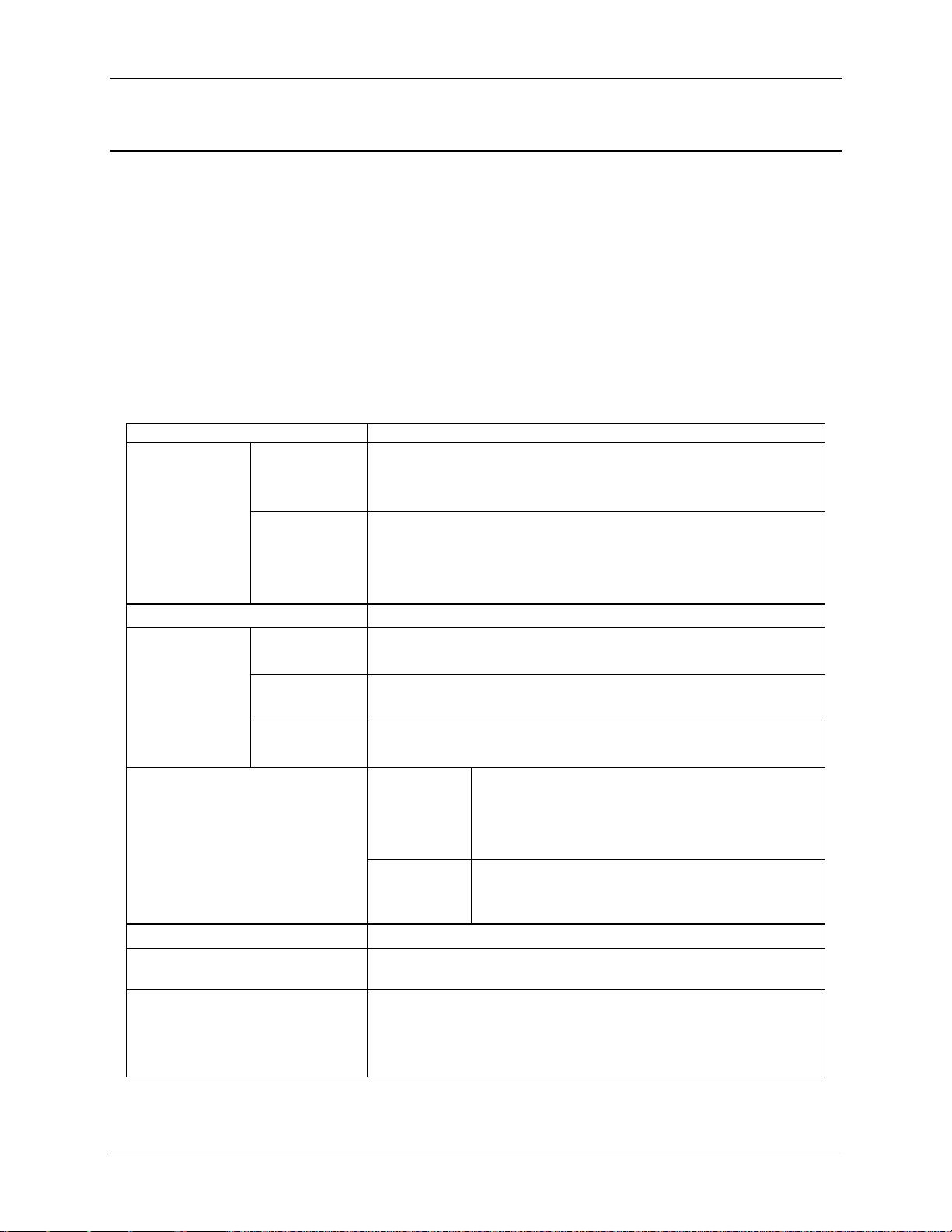
2.1 Chassis Views
Figure 1. Server Chassis Overview (12 x 3.5” drive bay)
Figure 2. Server Chassis Overview (16 x 2.5” drive bay)
Revision 2.21
Page 18
Product Overview Intel® Server Chassis H2000G Product Family TPS
6
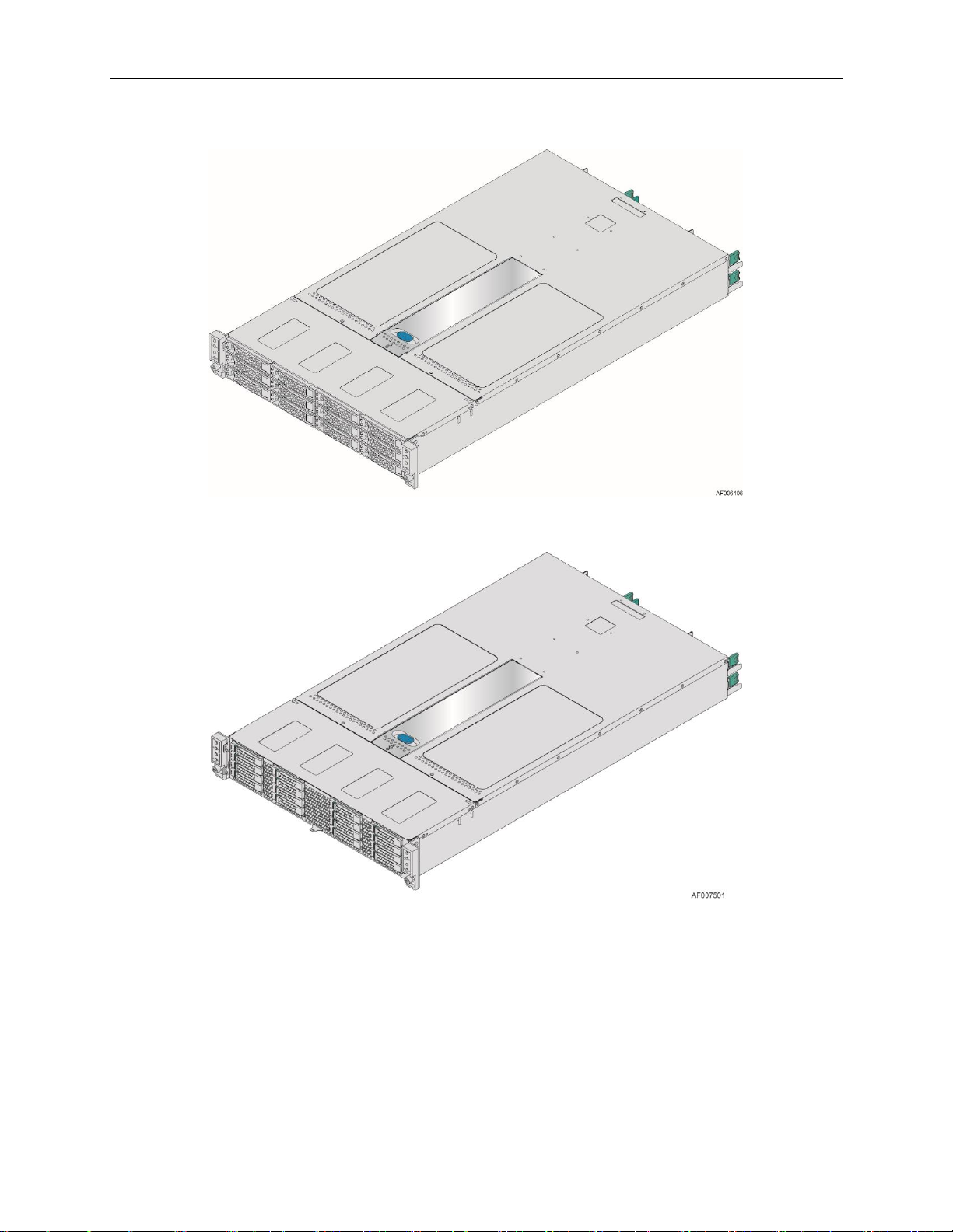
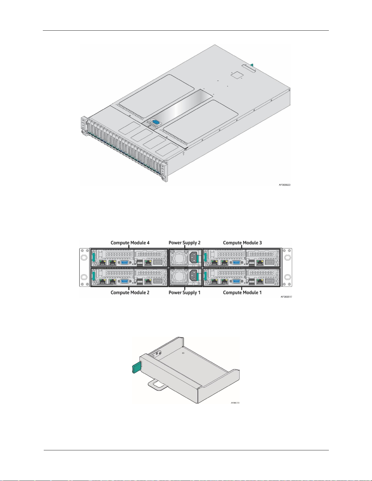
Figure 3. Server Chassis Overview (24 x 2.5” drive bay)
Figure 4. Server Chassis Rear View
Figure 5. Dummy Tray Cover
Revision 2.21
Page 19
Intel® Server Chassis H2000G Product Family TPS Product Overview
7
Parameter
Limits
Temperature
Operating
ASHRAE Class A2 – Continuous Operation. 10°C to 35°C (50°F to 95°F) with
the maximum rate of change not to exceed 10°C per hour
ASHRAE Class A3 – Includes operation up to 40°C for up to 900 hours per
ASHRAE Class A4 – Includes operation up to 45° for up to 90 hours per year
Non-Operating
-40°C to 70°C (-40°F to 158°F)
Altitude
Operating
Support for operation up to 3050m with ASHRAE class deratings.
Humidity
Non-Operating
50% to 90%, non-condensing with a maximum wet bulb of 28° C (at
temperatures from 25°C to 35°C)
Shock
Operating
Half sine, 2g, 11 mSec
Unpackaged
Trapezoidal, 25g, velocity change 175 inches/second
Packaged
ISTA (International Safe Transit Association) Test Procedure 3A
Vibration
Unpackaged
5 Hz to 500 Hz 2.20 g RMS random
Packaged
ISTA (International Safe Transit Association) Test Procedure 3A
AC-DC
Voltage
90 V to 132 V and 180 V to 264 V
Frequency
47 Hz to 63 Hz
Source Interrupt
No loss of data for power line drop-out of 12 mSec
Surge Non-
operating and
operating
Unidirectional
Line to earth Only
AC Leads 2.0 kV
I/O Leads 1.0 kV
ESD
Air Discharged
12.0 kV
Contact Discharge
8.0 kV
2.2 Environmental Limits
The following table defines the system level operating and non-operating environmental
limits.
Table 2. System Environmental Limits Summary
Disclaimer Note: Intel ensures the unpackaged server board and chassis meet the shock
requirement mentioned above through its own chassis development and configuration. It is the
responsibility of the system integrator to determine the proper shock level of the board and
chassis if the system integrator chooses different configuration or different chassis. Intel
Corporation cannot be held responsible, if components fail or the server board does not
operate correctly when used outside any of its published operating or non-operating limits.
Revision 2.21
Page 20

Product Overview Intel® Server Chassis H2000G Product Family TPS
8
A
Front Control Panels
B
Drive bays
C
Power Distribution Module
D
Power Supply Modules
E
Hot Swap Back Plane (attached to the drive cage)
2.3 Chassis Parts
Note: Not shown – Rack slide rail and power distribution module cover
Figure 6. Major Server Chassis Parts (12 x 3.5” drive bay)
Revision 2.21
Page 21

Intel® Server Chassis H2000G Product Family TPS Product Overview
9
A
Front Control Panels
B
Drive bays
C
Power Distribution Module
D
Power Supply Modules
E
Hot Swap Back Plane (attached to the drive cage)
Note: Not shown – Rack slide rail and power distribution module cover
Figure 7. Major Server Chassis Parts (16 x 2.5” drive bay)
Revision 2.21
Page 22
Product Overview Intel® Server Chassis H2000G Product Family TPS
10
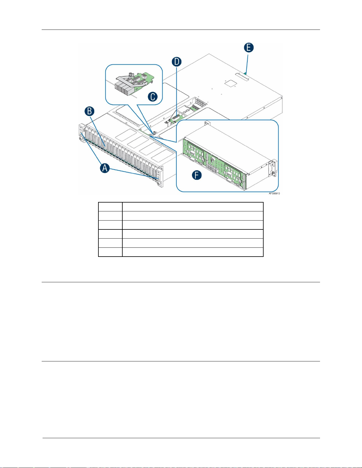
A
Front Control Panels
B
Drive bays
C
Power Interposer Board (24 x 2.5” drive chassis only)
D
Power Distribution Module
E
Power Supply Modules
F
Hot Swap Backplane (attached to the drive cage)
Note: Not shown – Rack slide rail and power distribution module cover
Figure 8. Major Server Chassis Parts (24 x 2.5” drive bay)
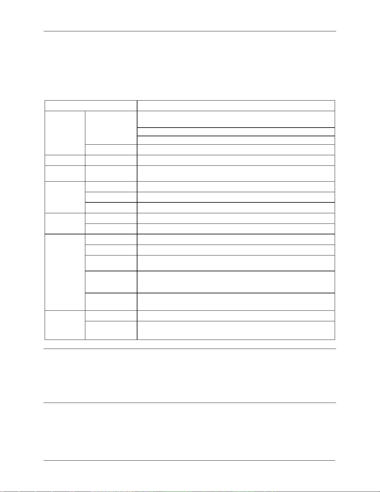
Notes:
1. The blank compute module bay must be covered by a dummy tray cover. When removed,
keep the dummy tray cover properly for future use.
2. The compute module bay in the chassis requires either a compute module being installed
and powered up or a dummy tray cover installed to maintain proper thermal environment
for the other running compute modules in the same chassis. In case of a compute module
failure, remove the failed compute module, and replace with a dummy tray cover until the
new compute module is installed.
Revision 2.21
Page 23

Intel® Server Chassis H2000G Product Family TPS Product Overview
11
Intel® Server Chassis
H2312XXKR2, H2312XXLR2
Intel® Server Chassis
H2216XXKR2, H2216XXLR2
Intel® Server Chassis
H2224XXKR2, H2224XXLR2
SATA/SAS Drives (3.5-inch)
Up to 12
Not Supported
Not Supported
SATA/SAS Drives (2.5-inch)
Up to 12
Up to 16
Up to 24
(1)
PCIe* SFF Devices
Not Supported
Not Supported
Up to 8
(2)
2.4 Drive and Peripheral Bays
Note (1): Intel® SATA SSDs and 3rd party SAS drives were validated on the H2224XXKR2 and
H2224XXLR2 chassis.
Note (2): As the PCIe* SFF device (NVMe SSD) shares the drive slots with SAS drive, so when
support 8 NVMe SSD, SAS drive number will decrease from 24 to 16.
Figure 9. 12 x 3.5” Drive Chassis Front View
Figure 10. 16 x 2.5” Drive Chassis Front View
Figure 11. 24 x 2.5” Drive Chassis Front View
Revision 2.21
Page 24

Product Overview Intel® Server Chassis H2000G Product Family TPS
12
2.5 Front Bezel Support
The Intel® Server Chassis H2000G product family provides front panel bezel. The bezel
provides protection to chassis drive bays with a lock to the chassis. The front view of the bezel
is as below.
Figure 12. Front Bezel
2.6 Rack and Cabinet Mounting Options
The server chassis is designed to support 19 inches wide by up to 30 inches deep server
cabinets. The server chassis bundles with the following Intel® rack mount option:
The basic slide rail kit (Product order code – AXXELVRAIL) is designed to mount the
chassis into a standard (19 inches wide by up to 30 inches deep) EIA-310D compatible
server cabinet.
The premium quality rails (Product order code – AXXFULLRAIL) can support the travel
distance 780mm, full extension from rack.
Caution: THE MAXIMUM RECOMMENDED SERVER WEIGHT FOR THE RACK RAILS CAN BE
FOUND at http://www.intel.com/support/motherboards/server/sb/CS-033655.htm. EXCEEDING
THE MAXIMUM RECOMMENDED WEIGHT OR MISALIGNMENT OF THE SERVER MAY RESULT IN
FAILURE OF THE RACK RAILS HOLDING THE SERVER. Use of a mechanical assist to install and
align server into the rack rails is recommended.
Advisory Note: To support shipment of the server chassis while installed in a rack with the rack
mount rail kit, user should ensure the server cabinet and its package can support the shipment
under the actual transport conditions.
Revision 2.21
Page 25
Intel® Server Chassis H2000G Product Family TPS Power Subsystem
13
3. Power Subsystem
The server chassis supports 1600W and 2130W AC 1+1 hot-swap power supply module and
two power distribution boards which can support 2U rack high density server.
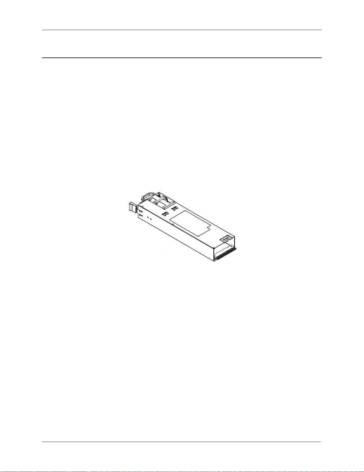
3.1 Power Supply Overview
The power supply module has a simple retention mechanism to retain the module self once it
is inserted. This mechanism withstands the specified mechanical shock and vibration
requirements. The power distribution board is fixed in the chassis with screws. Using existing
power supply module provided by vendor with updated PMBus* and custom-made power
connector board the server chassis supports four compute modules. The power supply has
two outputs: 12V and 12V standby. The input is auto ranging and power factor corrected. The
PMBus* features are requirements for AC silver rated box power supply for use in server
systems based on the Intel® Server Chassis H2000G product family. This specification is based
on the PMBus* Specifications part I and II, revision 1.1.
Figure 13. 1600W and 2130W AC Power Supply Module Overview
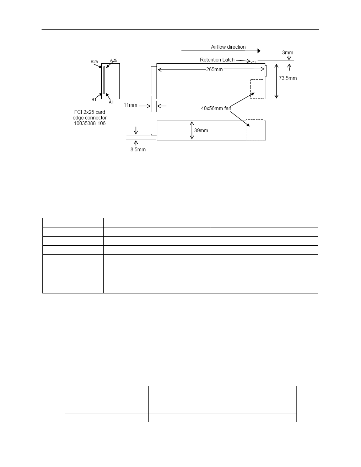
3.1.1 Power Supply Dimension
The physical size of the power supply enclosure is 39/40mm x 73.5mm x 265mm. The power
supply contains a single 40mm fan. The power supply has a card edge output that interfaces
with a 2x25 card edge connector in the chassis. The AC plugs directly into the external face of
the power supply.
Revision 2.21
Page 26
Power Subsystem Intel® Server Chassis H2000G Product Family TPS
14
1600W Power Supply
2130W Power Supply
Wattage
1600W (Energy Smart)
2130W (Energy Smart)
Voltage
90-264 VAC, auto-ranging, 47 Hz-63 Hz
90-264 VAC, auto-ranging, 47 Hz-63 Hz
Heat Dissipation
5459 BTU/hr
7268 BTU/hr
Maximum Inrush
Current
Under typical line conditions and over the
entire chassis ambient operating range,
the inrush current may reach 65 A per
power supply for 5 ms
Under typical line conditions and over the
entire chassis ambient operating range,
the inrush current may reach 65 A per
power supply for 5 ms
80 Plus rating
Platinum
Platinum
Cable Type
SJT
Wire Size
16 AWG
Temperature Rating
105º C
Amperage Rating
13A
Figure 14. AC Power Supply Unit Dimension Overview
3.1.2 AC Power Supply Unit General Data
Below is general specification data for AC power supply unit.
Table 3. Specification Data for AC Power Supply Unit
3.1.3 AC Input Connector
The power supply has an internal IEC320 C14 power inlet. The inlet is rated for a minimum of
10A at 250VAC.
3.1.4 AC Power Cord Specification Requirements
The AC power cord used meets the following specification requirements.
Table 4. AC Power Cord Specification
Revision 2.21
Page 27

Intel® Server Chassis H2000G Product Family TPS Power Subsystem
15
Cable Type
SJT
PSU Output Connector
A1
GND
B1
GND
A2
GND
B2
GND
A3
GND
B3
GND
A4
GND
B4
GND
A5
GND
B5
GND
A6
GND
B6
GND
A7
GND
B7
GND
A8
GND
B8
GND
A9
GND
B9
GND
A10
+12V
B10
+12V
A11
+12V
B11
+12V
A12
+12V
B12
+12V
A13
+12V
B13
+12V
A14
+12V
B14
+12V
A15
+12V
B15
+12V
A16
+12V
B16
+12V
A17
+12V
B17
+12V
A18
+12V
B18
+12V
A19
PMBus SDA*
B19
A0* (SMBus address)
A20
PMBus SCL*
B20
A1* (SMBus address)
A21
PSON
B21
12V STBY
A22
SMBAlert#
B22
Cold Redundancy Bus*
A23
Return Sense
B23
12V load share bus
A24
+12V Remote Sense
B24
No Connect
A25
PWOK
B25
CRPS Compatibility Check pin*
3.1.5 Power Supply Unit DC Output Connector
The DC output connector pin-out is defined as follows.
Table 5. DC Output Power Connector
3.1.6 Handle Retention
The power supply has a handle to assist extraction. The module is able to be inserted and
extracted without the assistance of tools. The power supply also has a latch which retains the
power supply into the chassis and prevents the power supply from being inserted or extracted
from the chassis when the AC power cord is pulled into the power supply.
The handle protects the operator from any burn hazard through the use of industrial designed
plastic handle or equivalent material.
Revision 2.21
* Refer to the spec of CRPS Common Requirements Specification.
Page 28

Power Subsystem Intel® Server Chassis H2000G Product Family TPS
16
Power Supply Condition
LED State
Output ON and OK
Solid GREEN
No AC power to all power supplies
OFF
AC present/Only 12VSB on (PS off) or PS in Cold redundant state
1Hz Blink GREEN
AC cord unplugged or AC power lost; with a second power supply in parallel still with AC
input power.
Solid AMBER
Power supply warning events where the power supply continues to operate; high temp,
high power, high current, slow fan.
1Hz Blink Amber
Power supply critical event causing a shutdown; failure, OCP, OVP, Fan Fail
Solid AMBER
Power supply FW updating
2Hz Blink GREEN
A
Power Distribution Board 1
B
Power Distribution Board 2
C
Power Supply Unit #2 (upper) and #1 (lower)
D
PSU cage
3.1.7 LED Marking and Identification
The power supply is using a bi-color LED: Amber and Green for status indication. The
following table shows the LED states for each power supply operating state.
Table 6. Power Supply Status LED
3.1.8 Power Distribution Module
The power distribution module is at the middle of the chassis and consists of two Power
Distribution Boards (PDBs) to support Common Redundant Power Supplies (CRPS).
Following is the Power Distribution Module overview.
Figure 15. Power Cage Overview
Revision 2.21
Page 29
Intel® Server Chassis H2000G Product Family TPS Power Subsystem
17
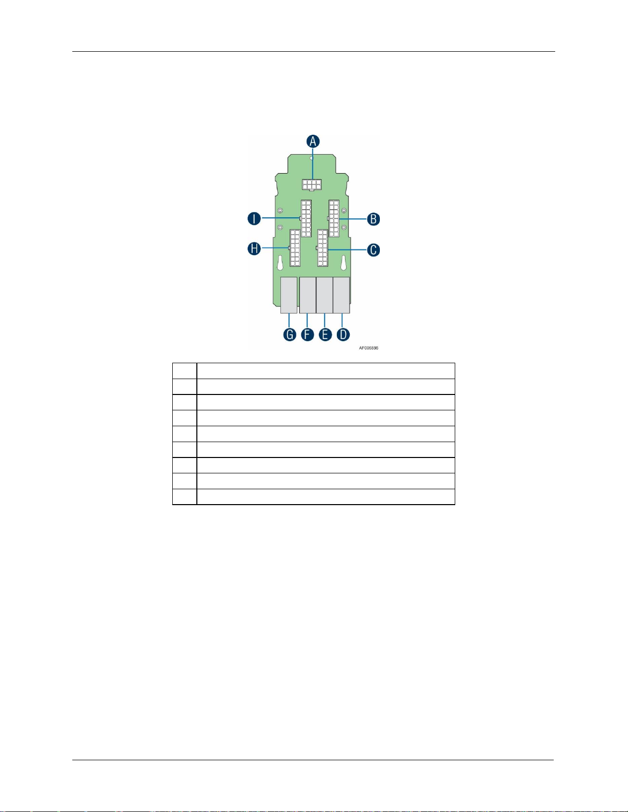
A
2x4 pin 5V Power Connector
B
2x8 pin 12V Power Connector (to PDB)
C
2x8 pin 12V Power Connector (to PDB)
D
12V Power Connector (to backplane)
E
12V Power Connector (to backplane)
F
12V Power Connector (to backplane)
G
12V Power Connector (to backplane)
H
2x8 pin 12V Power Connector (to PDB)
I
2x8 pin 12V Power Connector (to PDB)
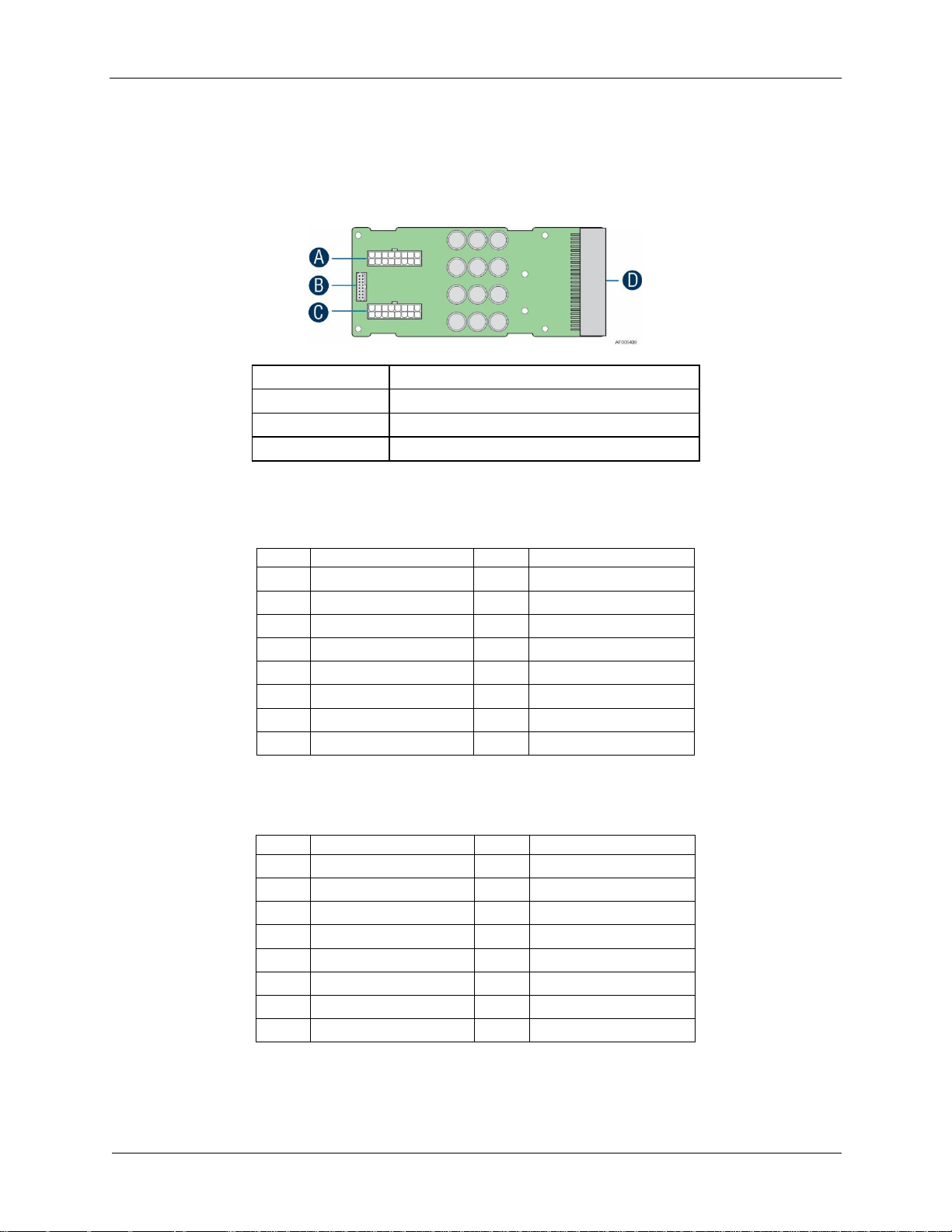
3.1.9 Power Interposer Board
The power interposer board is only used in 24 x 2.5” drive chassis as the interposer between
power distribution board and the backplane.
Figure 16. Power Interposer Board Top View
Revision 2.21
Page 30
Power Subsystem Intel® Server Chassis H2000G Product Family TPS
18
A
Main Power Output Connector
B
Control Signal Connector
C
Main Power Output Connector
D
Power Supply Unit Connector
Pin
Description
Pin
Description
1
GND
9
+12V
2
GND
10
+12V
3
GND
11
+12V
4
GND
12
+12V
5
GND
13
+12V
6
GND
14
+12V
7
GND
15
+12V
8
GND
16
+12V
Pin
Description
Pin
Description
1
PMBus SDA
2
For A0 addressing
3
PMBus SCL
4
PSON#
5
OCP_SHTDN#
6
12V Load Share Bus
7
SMBAlert#
8
Cold Redundancy Bus
9
Reserved
10
PWOK
11
Reserved
12
Compatibility Bus
13
Reserved
14
+12VSB
15
+12VSB
16
Key Pin (removed)
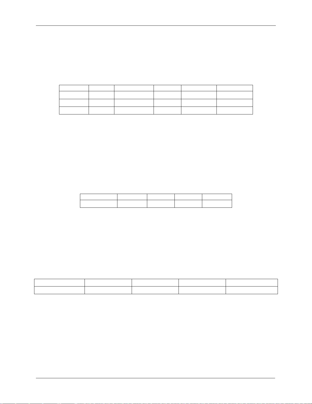
3.1.10 Power Cage Output Pin Assignment
The power cage provides +12V and +12V
output to the server chassis. Each PDB has two
STB
2x9 power output cable to chassis backplane, together with one 2x8 signal control cable for
power management. Refer to the following table for PDB pin assignment.
Figure 17. Power Distribution Board
Table 7. Pin Assignment of Power Output Connector
Revision 2.21
Table 8. Pin Assignment of Control Signal Connector
Page 31
Intel® Server Chassis H2000G Product Family TPS Power Subsystem
19
Parameter
Min
Rated
Max
Start-up VAC
Power-off VAC
110VAC
90 V
rms
100-127 V
rms
140 V
rms
85 VAC± 4VAC
70VAC±5VAC
220VAC
180 V
rms
200-240 V
rms
264 V
rms
85 VAC± 4VAC
70VAC±5VAC
Frequency
47 Hz
50/60 Hz
63 Hz
Output Power
10% Load
20% Load
50% Load
100% Load
Power factor
> 0.80
> 0.90
> 0.90
> 0.95
Loading
100% of Maximum
50% of Maximum
20% of Maximum
10% of Maximum
Minimum Efficiency
91%
94%
90%
82%
3.2 AC Input Specification
3.2.1 Input Voltage and Frequency
The power supply operates within all specified limits over the following input voltage range.
Table 9. AC Input Rating
Notes:
1. Maximum input current at low input voltage range is measured at 90VAC, at max load.
2. Maximum input current at high input voltage range is measured at 180VAC, at max load.
3. This requirement is not to be used for determining agency input current markings.
3.2.2 AC input Power Factor
The power supply meets the power factor requirements stated in the Energy Star* Program
Requirements for Computer Servers. These requirements are stated below.
Table 10. Typical Power Factor
3.2.3 Efficiency
The following table provides the required minimum efficiency level at various loading
conditions. These are provided at different load levels; 100%, 50%, 20%, and 10%. Output is
loaded according to the proportional loading method defined by 80 Plus in Generalized
Internal Power Supply Efficiency Testing Protocol, Rev 6.4.3.
Table 11. Platinum Efficiency Requirement
3.2.4 AC Line Fuse
The power supply has one line fused in the single line fuse on the line (Hot) wire of the AC
input. The line fusing is acceptable for all safety agency requirements. The input fuse is a slow
blow type. AC inrush current does not cause the AC line fuse to blow under any conditions. All
protection circuits in the power supply do not cause the AC fuse to blow unless a component
in the power supply has failed. This includes DC output load short conditions.
Revision 2.21
Page 32

Power Subsystem Intel® Server Chassis H2000G Product Family TPS
20
Loading
Holdup Time
70%
10.6msec
3.2.5 AC Line Inrush
AC line inrush current shall not exceed 65A peak, for up to one-quarter of the AC cycle, after
which, the input current should be no more than the specified maximum input current. The
peak inrush current shall be less than the ratings of its critical components (including input
fuse, bulk rectifiers, and surge limiting device).
The power supply meets the inrush requirements for any rated AC voltage, during turn on at
any phase of AC voltage, during a single cycle AC dropout condition as well as upon recovery
after AC dropout of any duration, and over the specified temperature range (Top).
3.2.6 AC Line Dropout/Holdup
An AC line dropout is defined to be when the AC input drops to 0VAC at any phase of the AC
line for any length of time. During an AC dropout the power supply meets dynamic voltage
regulation requirements. An AC line dropout of any duration shall not cause tripping of control
signals or protection circuits. If the AC dropout lasts longer than the holdup time, the power
supply should recover and meet all turn on requirements. The power supply shall meet the AC
dropout requirement over rated AC voltages and frequencies. A dropout of the AC line for any
duration shall not cause damage to the power supply.
Table 12. AC Power Holdup Requirement
The 12V
output voltage should stay in regulation under its full load (static or dynamic)
STB
during an AC dropout of 70ms min (=12VSB holdup time) whether the power supply is in ON
or OFF state (PSON asserted or de-asserted).
3.2.7 AC Line Fast Transient (EFT) Specification
The power supply meets the EN61000-4-5 directive and any additional requirements in
IEC1000-4-5: 1995 and the Level 3 requirements for surge-withstand capability, with the
following conditions and exceptions:
These input transients do not cause any out-of-regulation conditions, such as
overshoot and undershoot, nor do they cause any nuisance trips of any of the power
supply protection circuits.
The surge-withstand test does not produce damage to the power supply.
The supply meets surge-withstand test conditions under maximum and minimum DC-output
load conditions.
3.2.8 Hot Plug
The power supply is designed to allow connection into and removal from the chassis without
removing power to the chassis. During any phase of insertion, start-up, shutdown, or removal,
Revision 2.21
Page 33

Intel® Server Chassis H2000G Product Family TPS Power Subsystem
21
Level
Description
A
The apparatus shall continue to operate as intended. No degradation of performance.
B
The apparatus shall continue to operate as intended. No degradation of performance beyond
spec limits.
C
Temporary loss of function is allowed provided the function is self-recoverable or can be
restored by the operation of the controls.
the power supply does not cause any other like modules in the chassis to deviate outside of
their specifications. When AC power is applied, the auxiliary supply shall turn on providing
bias power internal to the supply and the 5VSB standby output.
3.2.9 Susceptibility Requirements
The power supply meets the following electrical immunity requirements when connected to a
cage with an external EMI filter, which meets the criteria, defined in the SSI document EPS
Power Supply Specification. For further information on customer standards, request a copy of
the customer Environmental Standards Handbook.
Table 13. Performance Criteria
3.2.10 Electrostatic Discharge Susceptibility
The power supply complies with the limits defined in EN 55024: 1998 using the IEC
61000-4-2:1995 test standard and performance criteria B defined in Annex B of CISPR 24.
3.2.11 Fast Transient/Burst
The power supply complies with the limits defined in EN 55024: 1998 using the IEC
61000-4-4:1995 test standard and performance criteria B defined in Annex B of CISPR 24.
3.2.12 Radiated Immunity
The power supply complies with the limits defined in EN 55024: 1998 using the IEC
61000-4-3:1995 test standard and performance criteria A defined in Annex B of CISPR 24.
3.2.13 Surge Immunity
The power supply is tested with the chassis for immunity to AC Ring wave and AC
Unidirectional wave, both up to 2kV, per EN 55024:1998, EN 61000-4-5:1995 and ANSI
C62.45: 1992.
The pass criteria include the following:
No unsafe operation is allowed under any condition
All power supply output voltage levels to stay within proper spec levels
No change in operating state or loss of data during and after the test profile
No component damage under any condition
Revision 2.21
Page 34

Power Subsystem Intel® Server Chassis H2000G Product Family TPS
22
AC Line Sag (10 sec interval between each sagging)
Duration
Sag
Operating AC Voltage
Line
Frequency
Performance Criteria.
0 to ½ AC
cycle
95%
Nominal AC Voltage
ranges
50/60Hz
No loss of function or performance.
> 1 AC cycle
>30%
Nominal AC Voltage
ranges
50/60Hz
Loss of function acceptable, selfrecoverable.
AC Line Surge
Duration
Surge
Operating AC Voltage
Line
Frequency
Performance Criteria
Continuous
10%
Nominal AC Voltages
50/60Hz
No loss of function or performance
0 to ½ AC
cycle
30%
Mid-point of nominal AC
Voltages
50/60Hz
No loss of function or performance
The power supply complies with the limits defined in EN 55024: 1998 using the IEC
61000-4-5:1995 test standard and performance criteria B defined in Annex B of CISPR 24.
3.2.14 AC Line Transient Specification
AC line transient conditions are defined as “sag” and “surge” conditions. “Sag” conditions are
also commonly referred to as “brownout”; these conditions are defined as the AC line voltage
dropping below nominal voltage conditions. “Surge” is defined to refer to conditions when the
AC line voltage rises above nominal voltage.
The power supply meets the requirements under the following AC line sag and surge
conditions.
Table 14. AC Line Sag Transient Performance
Table 15. AC Line Surge Transient Performance
3.2.15 Power Recovery
The power supply recovers automatically after an AC power failure. AC power failure is
defined to be any loss of AC power that exceeds the dropout criteria.
3.2.16 Voltage Interruptions
The power supply complies with the limits defined in EN 55024: 1998/A1: 2001/A2: 2003
using the IEC 61000-4-11: Second Edition: 2004-03 test standard and performance criteria C
defined in Annex B of CISPR 24.
3.2.17 AC Line Isolation
The power supply meets all safety agency requirements for dielectric strength. Transformers’
isolation between primary and secondary windings complies with the 3000Vac (4242Vdc)
dielectric strength criteria. If the working voltage between primary and secondary dictates a
Revision 2.21
Page 35

Intel® Server Chassis H2000G Product Family TPS Power Subsystem
23
Cable Type
SJT
Wire Size
16 AWG
Temperature Rating
105ºC
Amperage Rating
13 A
Voltage Rating
125 V
higher dielectric strength test voltage, the highest test voltage will be used. In addition the
insulation chassis complies with reinforced insulation per safety standard IEC 950. Separation
between the primary and secondary circuits, and primary to ground circuits, complies with the
IEC 950 spacing requirements.
3.2.18 AC Power Inlet
The AC input connector is an IEC 320 C-14 power inlet. This inlet is rated for 10A/250 VAC.
The AC power cord meets the following specification requirements.
Figure 18. AC Power Cord Specification
Revision 2.21
Page 36

Power Subsystem Intel® Server Chassis H2000G Product Family TPS
24
Parameter
Min
Max
Peak 2
Unit
+12V main (200-240VAC)
0.0
133
175 A +12VSTB 1
0.0
3.5
2.4
A
Vin
≥100VAC
≥110VAC
≥120VAC
P
o.max
1130W
1250W
1320W
Parameter
Min
Nom
Max
Unit
Tolerance
+12V
STB
+11.40V
+12.000V
+12.60V
Vrms
±5%
+12V
+11.40V
+12.000V
+12.60V
Vrms
±5%
3.3 DC Output Specification
3.3.1 Output Power/Currents
The following table defines the minimum power and current ratings. The power supply meets
both static and dynamic voltage regulation requirements for all conditions.
Table 16. Load Ratings for Single 1600W Power Supply Unit
Power rating for AC low line
Notes:
1. 12V
2. Length of time peak power can be supported based on thermal sensor and assertion of the SMBAlert#
3. The setting of I
4. The power supply must protect itself in case the system doesn't take any action based on SMBAlert/OCW
provides 4.0A peak load with single power supply. The power supply fan is allowed to run in
STB
standby mode for loads > 1.5A.
signal. Minimum peak power duration shall be 20 seconds without asserting the SMBAlert# signal.
< I
< I
needs to be followed to make the CLST work reasonably.
OCP
event.
Peak
OCW
3.3.2 Standby Output
The 12VSB output will be present when an AC input greater than the power supply turn on
voltage is applied.
3.3.3 Voltage Regulation
The power supply output voltages stay within the following voltage limits when operating at
steady state and dynamic loading conditions. These limits include the peak-peak ripple/noise.
These shall be measured at the output connectors.
Table 17. Voltage Regulation Limits
The combined output continuous power of all outputs does not exceed 3200W (1600W from
each 1600W power supply unit) or 4260W (2130W from each 2130W power supply unit).
Each output has a maximum and minimum current rating. The power supply meets both static
and dynamic voltage regulation requirements for the minimum dynamic loading conditions.
Revision 2.21
Page 37

Intel® Server Chassis H2000G Product Family TPS Power Subsystem
25
Output
Step Load Size
Load Slew Rate
Test Capacitive Load
+12V
STB
1.0A
0.25 A/sec
20 F
+12V
60% of max load
0.25 A/sec
2000 F
Output
Min
Max
Units
+12V
500
25,000
F
+12V
STB
20
3100
F
+12V
+12V
STB
120mVp-p
120mVp-p
The power supply meets only the static load voltage regulation requirements for the minimum
static load conditions.
3.3.4 Dynamic Loading
The output voltages remain within limits specified for the step loading and capacitive loading
specified in the table below. The load transient repetition rate is tested between 50Hz and
5kHz at duty cycles ranging from 10%-90%. The load transient repetition rate is only a test
specification. The step load may occur anywhere within the MIN load to the MAX load
conditions.
Table 18. Transient Load Requirements
Note: For dynamic condition +12V min loading is 1A.
3.3.5 Capacitive Loading
The power supply is stable and meets all requirements, with the following capacitive loading
conditions.
Table 19. Capacitive Loading Conditions
3.3.6 Ripple/Noise
The maximum allowed ripple/noise output of the power supply is defined in the table below.
This is measured over a bandwidth of 10Hz to 20MHz at the power supply output connectors.
A 10F tantalum capacitor in parallel with a 0.1F ceramic capacitor is placed at the point of
measurement.
Table 20. Ripple and Noise
3.3.7 Grounding
The output ground of the pins of the power supply provides the output power return path.
The output connector ground pins are connected to the safety ground (power supply
enclosure). This grounding is well designed to ensure passing the max allowed Common Mode
Noise levels.
Revision 2.21
Page 38

Power Subsystem Intel® Server Chassis H2000G Product Family TPS
26
The power supply is provided with a reliable protective earth ground. All secondary circuits
are connected to protective earth ground. Resistance of the ground returns to chassis does
not exceed 1.0 m. This path may be used to carry DC current.
3.3.8 Closed Loop Stability
The power supply is unconditionally stable under all line/load/transient load conditions
including capacitive load ranges specified in Section 3.3.5. A minimum of 45 degrees phase
margin and -10dB-gain margin is required. The power supply manufacturer shall provide
proof of the unit’s closed-loop stability with local sensing through the submission of Bode
plots. Closed-loop stability must be ensured at the maximum and minimum loads as
applicable.
3.3.9 Residual Voltage Immunity in Standby Mode
The power supply is immune to any residual voltage placed on its outputs (typically a leakage
voltage through the chassis from standby output) up to 500mV. There is no additional heat
generated, nor stressing of any internal components with this voltage applied to any
individual or all outputs simultaneously. It also does not trip the protection circuits during turn
on.
The residual voltage at the power supply outputs for no load condition will not exceed 100mV
when AC voltage is applied and the PSON# signal is de-asserted.
3.3.10 Common Mode Noise
The Common Mode noise on any output does not exceed 350mVp-p over the frequency band
of 10Hz to 20MHz.
The measurement is made across a 100Ω resistor between each of DC outputs,
including ground at the DC power connector and chassis ground (power subsystem
enclosure).
The test setup uses a FET probe such as Tektronix model P6046 or equivalent.
3.3.11 Soft Starting
The power supply contains control circuit which provides monotonic soft start for its outputs
without overstress of the AC line or any power supply components at any specified AC line or
load conditions.
3.3.12 Zero Load Stability Requirement
When the power subsystem operates in a no load condition, it does not need to meet the
output regulation specification, but it must operate without any tripping of over-voltage or
other fault circuitry. When the power subsystem is subsequently loaded, it must begin to
regulate and source current without fault.
Revision 2.21
Page 39

Intel® Server Chassis H2000G Product Family TPS Power Subsystem
27
Item
Description
Min.
Max.
Units
T
vout_rise
Output voltage rise time
5.0 *
70 *
ms
T
sb_on_delay
Delay from AC being applied to 12VSBbeing within
regulation.
1500
ms
T
ac_on_delay
Delay from AC being applied to all output voltages being
within regulation.
3000
ms
T
vout_holdup
Time 12Vl output voltage stay within regulation after loss
of AC.
13 ms
T
pwok_holdup
Delay from loss of AC to de-assertion of PWOK
10.6
ms
T
pson_on_delay
Delay from PSON# active to output voltages within
regulation limits.
5
400
ms
T
pson_pwok
Delay from PSON# deactivate to PWOK being de-asserted.
5 ms
T
pwok_on
Delay from output voltages within regulation limits to
PWOK asserted at turn on.
100
500
ms
T
pwok_off
Delay from PWOK de-asserted to output voltages dropping
out of regulation limits.
1 ms
T
pwok_low
Duration of PWOK being in the de-asserted state during an
off/on cycle using AC or the PSON signal.
100 ms
T
sb_vout
Delay from 12VSBbeing in regulation to O/Ps being in
regulation at AC turn on.
50
1000
ms
3.3.13 Hot Swap Requirement
Hot swapping a power supply is the process of inserting and extracting a power supply from
an operating power system. During this process the output voltages remain within the limits
with the capacitive load specified. The hot swap test must be conducted when the system is
operating under static, dynamic, and zero loading conditions. The power supply will use a
latching mechanism to prevent insertion and extraction of the power supply when the AC
power cord is inserted into the power supply.
3.3.14 Forced Load Sharing
The +12V output has active load sharing. The output will share within 10% at full load. The
failure of a power supply will not affect the load sharing or output voltages of the other
supplies still operating. The supplies are able to load share in parallel and operate in a
hot-swap/redundant 1+1 configurations. The 12VSBoutput is not required to actively share
current between power supplies (passive sharing). The 12VSBoutput of the power supplies is
connected together in the system so that a failure or hot swap of a redundant power supply
does not cause these outputs to go out of regulation in the system.
3.3.15 Timing Requirement
These are the timing requirements for the power supply operation. The output voltages must
rise from 10% to within regulation limits (T
) within 5 to 70ms. For 12VSB, it is allowed to
vout_rise
rise from 1.0 to 25ms. All outputs must rise monotonically. The table below shows the timing
requirements for the power supply being turned on and off through the AC input, with PSON
held low and the PSON signal, with the AC input applied.
Table 21. Timing Requirement
Revision 2.21
Page 40

Power Subsystem Intel® Server Chassis H2000G Product Family TPS
28
T
12VSB_holdup
Time the 12VSBoutput voltage stays within regulation after
loss of AC.
70 ms
AC Input
Vout PWOK
12Vsb
PSON
T
sb_on_delay
T
AC_on_delay
T
pwok_on
T
vout_holdup
T
pwok_holdup
T
pson_on_delay
T
sb_on_delay
T
pwok_on
T
pwok_off
T
pwok_off
T
pson_pwok
T
pwok_low
T
sb_vout
AC turn on/off cycle
PSON turn on/off cycle
T
5Vsb_holdup
* The 12VSTB output voltage rise time shall be from 1.0ms to 25ms.
Figure 19. Turn On/Off Timing (Power Supply Signals)
Revision 2.21
Page 41

Intel® Server Chassis H2000G Product Family TPS Power Subsystem
29
Enable (V)
Percent
Power (W)
Disable (V)
Percent
Power (W)
Cold
Standby 1
(02h)
3.2
40.00%
640(±5%)
1.44
18.00%
576(±5%)
3.4 Power Supply Cold Redundancy Support
Power supplies that support cold redundancy can be enabled to go into a low-power state
(that is, cold redundant state) in order to provide increased power usage efficiency when
system loads are such that both power supplies are not needed. When the power subsystem
is in Cold Redundant mode, only the needed power supply to support the best power delivery
efficiency is ON. Any additional power supply including the redundant power supply, is in Cold
Standby state.
Each power supply has an additional signal that is dedicated to supporting Cold Redundancy;
CR_BUS. This signal is a common bus between all power supplies in the system. CR_BUS is
asserted when there is a fault in any power supply OR the power supplies output voltage falls
below the Vfault threshold. Asserting the CR_BUS signal causes all power supplies in Cold
Standby state to power ON.
Enabling power supplies to maintain best efficiency is achieved by looking at the Load Share
bus voltage and comparing it to a programmed voltage level through a PMBus command.
Whenever there is no active power supply on the Cold Redundancy bus driving a HIGH level
on the bus all power supplies are ON no matter their defined Cold Redundant roll (active or
Cold Standby). This guarantees that incorrect programming of the Cold Redundancy states of
the power supply will never cause the power subsystem to shut down or become over loaded.
The default state of the power subsystem is all power supplies ON. There needs to be at least
one power supply in Cold Redundant Active state or Standard Redundant state to allow the
Cold Standby state power supplies to go into Cold Standby state.
Caution: Installing two Power Supply Units with different wattage ratings on a system is not
supported. This will not provide Power Supply Redundancy and causes the system to log
multiple errors.
3.4.1 1600W CRPS Cold Redundancy
If the output power is less than 640W (40%), the cold redundant function will be enable. Thus
you will see one PSU working normally. The second PSU will be in CR mode. The Power
Supply LED is green blinking.
Table 22. 1600W CRPS Cold Redundancy Threshold
3.4.2 2130W CRPS Cold Redundancy
If the output power is less than 852W (40%), the cold redundant function will be enable. Thus
you will see one PSU working normally. The second PSU will be in CR mode. The Power
Supply LED is green blinking.
Revision 2.21
Page 42
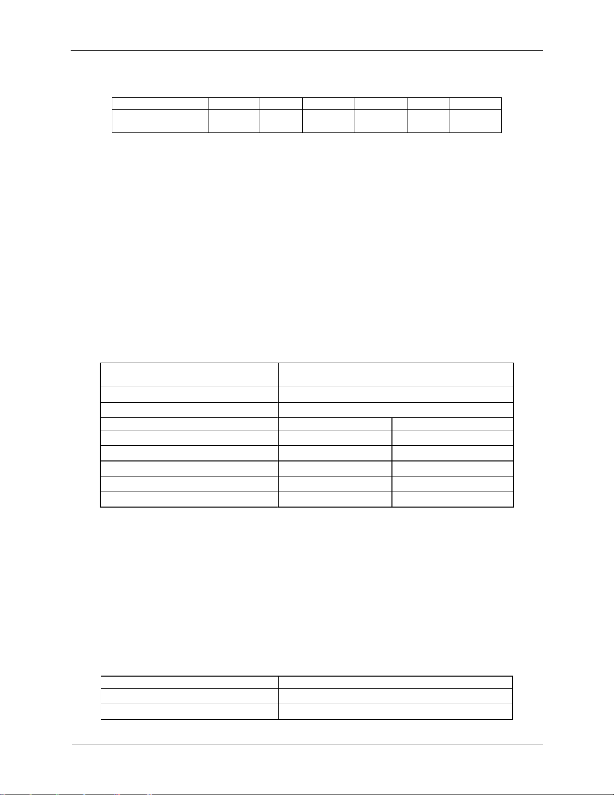
Power Subsystem Intel® Server Chassis H2000G Product Family TPS
30
Enable (V)
Percent
Power (W)
Disable (V)
Percent
Power (W)
Cold Standby 1 (02h)
2.839V1
40.00%
852(±5%)
1.115V1
30.00%
639(±5%)
Signal Type
Accepts an open collector/drain input from the system.
Pull-up to VSB located in power supply.
PSON# = Low
ON
PSON# = High or Open
OFF
MIN
MAX
Logic level low (power supply ON)
0V
1.0V
Logic level high (power supply OFF)
2.0V
3.46V
Source current, Vpson = low
4mA
Power up delay: T
pson_on_delay
5msec
400msec
PWOK delay: T
pson_pwok
50msec
Signal Type
PWOK = High
Power OK
PWOK = Low
Power Not OK
Table 23. 2130W CRPS Cold Redundancy Threshold
1
1A before trigger
3.5 Control and Indicator Functions
The following sections define the input and output signals from the power supply.
Signals that can be defined as low true use the following convention: Signal# = low true.
3.5.1 PSON# Input Signal
The PSON# signal is required to remotely turn on/off the power supply. PSON# is an active
low signal that turns on the +12V power rail. When this signal is not pulled low by the system,
or left open, the outputs (except the +12VSB) turn off. This signal is pulled to a standby
voltage by a pull-up resistor internal to the power supply. Refer to the table below for the
timing diagram.
Table 24. PSON# Signal Characteristics
3.5.2 PWOK (power good) Output Signal
PWOK is a power OK signal and will be pulled HIGH by the power supply to indicate that all
the outputs are within the regulation limits of the power supply. When any output voltage falls
below regulation limits or when AC power has been removed for a time sufficiently long so
that power supply operation is no longer guaranteed, PWOK will be de-asserted to a LOW
state. See the table below for a representation of the timing characteristics of PWOK. The start
of the PWOK delay time will be inhibited as long as any power supply output is in current limit.
Revision 2.21
Table 25. PWOK Signal Characteristics
Page 43

Intel® Server Chassis H2000G Product Family TPS Power Subsystem
31
Signal Type
MIN
MAX
Logic level low voltage, Isink=400uA
0V
0.4V
Logic level high voltage, Isource=200A
2.4V
3.46V
Sink current, PWOK = low
400uA
Source current, PWOK = high
2mA
PWOK delay: Tpwok_on
100ms
1000ms
PWOK rise and fall time
100sec
Power down delay: T pwok_off
1ms
200msec
Signal Type (Active Low)
Open collector/drain output from power supply.
Pull-up to VSB located in system.
Alert# = High
OK
Alert# = Low
Power Alert to system
MIN
MAX
Logic level low voltage, Isink=4 mA
0 V
0.4 V
Logic level high voltage, Isink=50 A
3.46 V
Sink current, Alert# = low
4 mA
Sink current, Alert# = high
50 A
Alert# rise and fall time
100 s
3.5.3 SMBAlert# Signal
This signal indicates that the power supply is experiencing a problem that the user should
investigate. This is asserted due to Critical events or Warning events. The signal will activate in
the case of critical component temperature reached a warning threshold, general failure, overcurrent, over-voltage, under-voltage, failed fan. This signal may also indicate the power supply
is reaching its end of life or is operating in an environment exceeding the specified limits.
This signal is to be asserted in parallel with LED turning solid Amber or blink Amber.
Table 26. SMBAlert# Signal Characteristics
Revision 2.21
Page 44

Power Subsystem Intel® Server Chassis H2000G Product Family TPS
32
Output Voltage
Input Voltage Range
1600W Over Current Limits
2130W Over current Limits
+12V
90 – 264VAC
180A min; 200A max
210A min; 230A max
+12V
STB
90 – 264VAC
2.5A min; 3A max
4.5A min; 5.5A max
Output Voltage
MIN (V)
MAX (V)
+12V
13.3
14.5
+12VSB
13.3
14.5
3.6 Protection Circuits
Protection circuits inside the power supply cause only the power supply’s main outputs to
shut down. If the power supply latches off due to a protection circuit tripping, an AC cycle OFF
for 15sec and a PSON# cycle HIGH for 1sec will be able to reset the power supply.
3.6.1 Current Limit (OCP)
The power supply has current limit to prevent the outputs from exceeding the values shown in
table below. If the current limits are exceeded, the power supply will shut down and latch off.
The latch will be cleared by toggling the PSON# signal or by an AC power interruption. The
power supply will not be damaged from repeated power cycling in this condition. 12VSB will
be auto-recovered after removing OCP limit.
Table 27. Over Current Protection
3.6.2 Over Voltage Protection (OVP)
The power supply over voltage protection is locally sensed. The power supply will shut down
and latch off after an over voltage condition occurs. This latch will be cleared by toggling the
PSON# signal or by an AC power interruption. The values are measured at the output of the
power supply’s connectors. The voltage will never exceed the maximum levels when
measured at the power connectors of the power supply connector during any single point of
fail. The voltage will never trip any lower than the minimum levels when measured at the
power connector. 12VSB will be auto-recovered after removing OVP limit.
Table 28. Over Voltage Protection (OVP) Limits
3.6.3 Over Thermal Protection
The power supply will be protected against over temperature conditions caused by loss of fan
cooling or excessive ambient temperature. In an OTP condition the PSU will shut down. When
the power supply temperature drops to within specified limits, the power supply will restore
power automatically, while the 12VSB remains always on. The OTP circuit has built in margin
so that the power supply will not oscillate on and off due to temperature recovering condition.
The OTP trip level has a minimum of 4C of ambient temperature margin.
Revision 2.21
Page 45

Intel® Server Chassis H2000G Product Family TPS Power Subsystem
33
PDB addressing Address0
0
1
Power supply PMBus* device
B0h
B2h
3.7 PMBus*
The PMBus* features are requirements for power supply unit for use in server systems. This
specification is based on the PMBus* specifications part I and II, revision 1.1. The power supply
device address locations are shown below.
Figure 20. Power Supply Device Address
The PMBus* from PDB is connected to the BMC of all four compute modules. Only one board
BMC is assigned to be the master BMC and communicate with PSU as single point. Other
board BMCs receive PSU data from the master BMC. In case the master BMC is down, one of
the slave board BMC will be promoted automatically as master BMC and maintain the
communication.
3.7.1 PSU Address Lines A0
Address pins A0 is used by end use system to allocate unit address to a power supply in
particular slot position.
For redundant systems there are two signals to set the address location of the power supply
once it is installed in the system; Address0 and Address1. For non-redundant systems the
power supply device address locations align with the Address0/Address1 location of 0/0.
Table 29. PSU Addressing
Revision 2.21
Page 46

Power Subsystem Intel® Server Chassis H2000G Product Family TPS
34
Output Loading
10% - 20%
> 20% -
50%
> 50% -
100%
READ_PIN and READ_EIN
See graphs below
READ_FAN
+/-500 RPM
READ_IOUT
+/-5%
+/-2%
+/-2%
READ_TEMPERATURE
+/- 3ºC
PMBus Input power monitoring accuracy
0
5
10
15
20
25
1000
950
900
850
800
750
700
650
600
550
500
450
400
350
300
250
200
150
100
50
37.5
Input power, W
Accuracy, +/- W
0.0%
1.0%
2.0%
3.0%
4.0%
5.0%
6.0%
Accuracy, +/-%
Accuracy, +/-W
Accuracy, +/-%
3.7.2 Accuracy
The sensor commands meet the following accuracy requirements. The accuracies are met
over the specified ambient temperature and the full range of rated input voltage.
Table 30. PMBus Accuracy
Revision 2.21
Figure 21. PMBus Monitoring Accuracy
Page 47
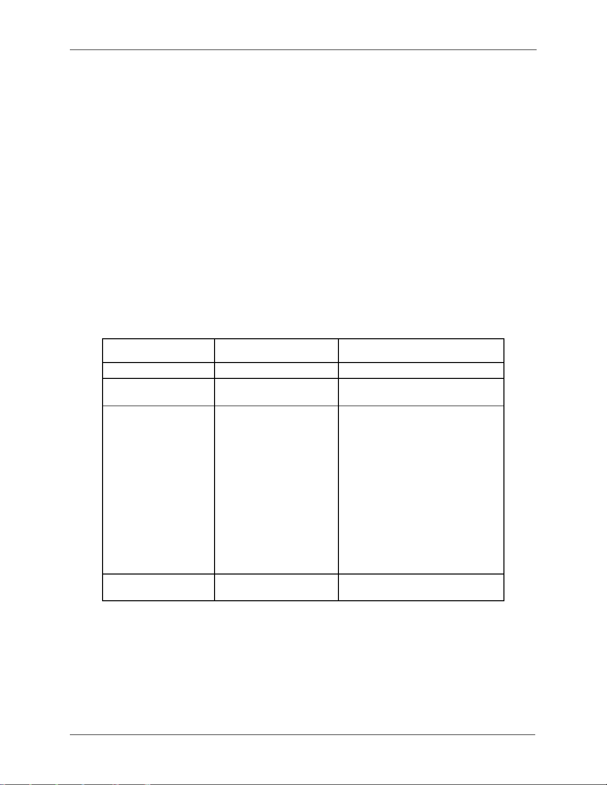
Intel® Server Chassis H2000G Product Family TPS Power Subsystem
35
Server Chassis Load with
2x 1600W supplies
System Power Redundancy
Mode
System behavior with one PSU AC lost
or failed
System Power Load
<1600W
Unconstrained Redundant
Mode
No system throttling. All 4 compute
modules work normally.
1600W< current load <
2160W
Optimal Redundant Mode
With BIOS setting “server
management - shutdown policy” set
to “disable” all compute modules in
the chassis may be throttled to
maintain power. This may cause lower
performance.
With BIOS “ server management-shutdown policy” set to “enable”,
compute module 3 and 4 will shut
down while compute module 1 and 2
keep running without throttling.
Compute module 1 and compute
module 2 will have no performance
loss.
>2160W
Non Redundant Mode
All compute modules in the chassis
may shut down.
3.8 Power Management Policy
When working with the Intel® Server Board S2600KP/S2600TP/S7200AP, the BMC on each
compute module will monitor its fans and temperature for critical failures. When there is a fan
failure and a critical temperature event at the same time, the compute module will be powered
down. When this occurs, the compute module will need to be manually powered back on.
Additionally on the Intel® Server Board S2600KP product family and Intel® Server Board
S2600TP product family and the Intel® Server Board S7200AP product family, the BMC on
compute module 3 and compute module 4 will monitor for a power supply over current
condition or power supply over temperature condition. If either of these occurs and the
Shutdown Policy has been enabled, the compute module will be powered down. When this
occurs, the compute module will need to be manually powered back on but if the over current
or over temperature event is detected again the compute module will be powered back off.
The following table shows the scheme of system power redundancy mode with compute
module behavior.
Table 31. Power Management Policy
The Shutdown Policy setting is only shown on compute module 3 and compute module 4, and
is disabled by default but can be enabled or disabled in the BIOS setup Server Management
page or by using the Set Shutdown Policy command.
Revision 2.21
Page 48

Cooling Subsystem Intel® Server Chassis H2000G Product Family TPS
36
Chassis
With Compute Module
Air Flow
H2312XXKR2/LR2
HNS2600KP
45-175CFM
H2216XXKR2/LR2
HNS2600KP
40-217CFM
H2224XXKR2/LR2
HNS2600TP
28-163CFM
H2312XXKR2/LR2
HNS2600TP
45-167CFM
H2216XXKR2/LR2
HNS2600TP
40-209CFM
H2312XXLR2
HNS7200AP
43-200CFM
H2216XXLR2
HNS7200AP
53-240CFM
4. Cooling Subsystem
The cooling subsystem refers to the chassis installed with compute modules. The cooling
subsystem contains the fans of each compute module and fans in the power supply units.
Both compute module fans and PSU fans work together as a thermal solution to the system.
For each compute module, several components and configuration requirements make up the
cooling subsystem. These include processors, chipsets, VR heatsinks, fans, CPU air-duct, and
drive bay population. All are necessary to provide and regulate the airflow and air pressure
needed to maintain the system thermals when operating at or below the maximum specified
thermal limits.
In order to maintain the necessary airflow within the system, you must properly install the air
duct, drive carrier, PSU dummy filler and the power distribution module cover.
Each compute module uses a variable fan speed control algorithm to provide adequate
cooling for the compute module and whole system at various ambient temperature
conditions, under various server workloads, and with the least amount of acoustic noise
possible. The fans operate at the lowest speed for any given condition to minimize acoustics.
The following table provides air flow data associated with the different product models within
this product family, and is provided for reference purposes only. The data was derived from
actual wind tunnel test and measurements using fully configured system. Lesser system
configurations may result in totally different results. As such, the CFM data that users get from
software may vary from the data listed in the table.
Table 32. Air Flow
4.1 Power Supply Fans
Each power supply module has one non-redundant dual rotor 40x56 mm fan. The fans
control the cooling of the power supply and some drive bays. These fans are not replaceable.
Therefore, if a power supply fan fails, you must replace the power supply module.
Revision 2.21
Page 49

Intel® Server Chassis H2000G Product Family TPS Cooling Subsystem
37
4.2 Drive Bay Population Requirement
In order to maintain chassis thermal requirements, you must fully populate all drive bays.
Drive carriers used for hot-swap drives must either have a drive installed or not have a drive
installed.
If only one power supply unit is used, a PSU dummy filler must be used to prevent
recirculation.
IMPORTANT: If the drive bay is missing or not fully populated, the system will not meet the
thermal cooling requirements, which will most likely result in degraded performance as a result
of throttling or thermal shutdown of the compute module. It is recommended to keep/apply
the dummy plastic blocker (as shipped with drive carrier) on any blank drive carrier.
Revision 2.21
Page 50

Drive Support Intel® Server Chassis H2000G Product Family TPS
38
5. Drive Support
The server chassis product family provides three SKUs to support different types of drives:
H2312XXKR2/LR2: Supports 12x 3.5" drives
H2216XXKR2/LR2: Supports 16x 2.5" drives
H2224XXKR2/LR2: Supports 24x 2.5" drives
5.1 Drive Bays Scheme
The Intel® Server Chassis H2000G product family can support up to 12 carrier-mounted
SATA/SAS 3.5” drives, or 16 carrier-mounted SATA/SAS 2.5" drives or 24 carrier-mounted
SAS 2.5" drives. The drives may be “electrically” hot-swapped while the chassis power is
applied, but you must take caution before hot-swapping while the compute module is
functioning under operating system/application control or data may be lost.
Below are drive configurations of different SKUs of the product family.
Note: Drives routed to the same compute module through the backplane are grouped and
numbered ONLY in the figure, not showing on the hardware.
Figure 22. 12 x 3.5” Drive Configuration
Figure 23. 16 x 2.5” Drive Configuration
Revision 2.21
Page 51
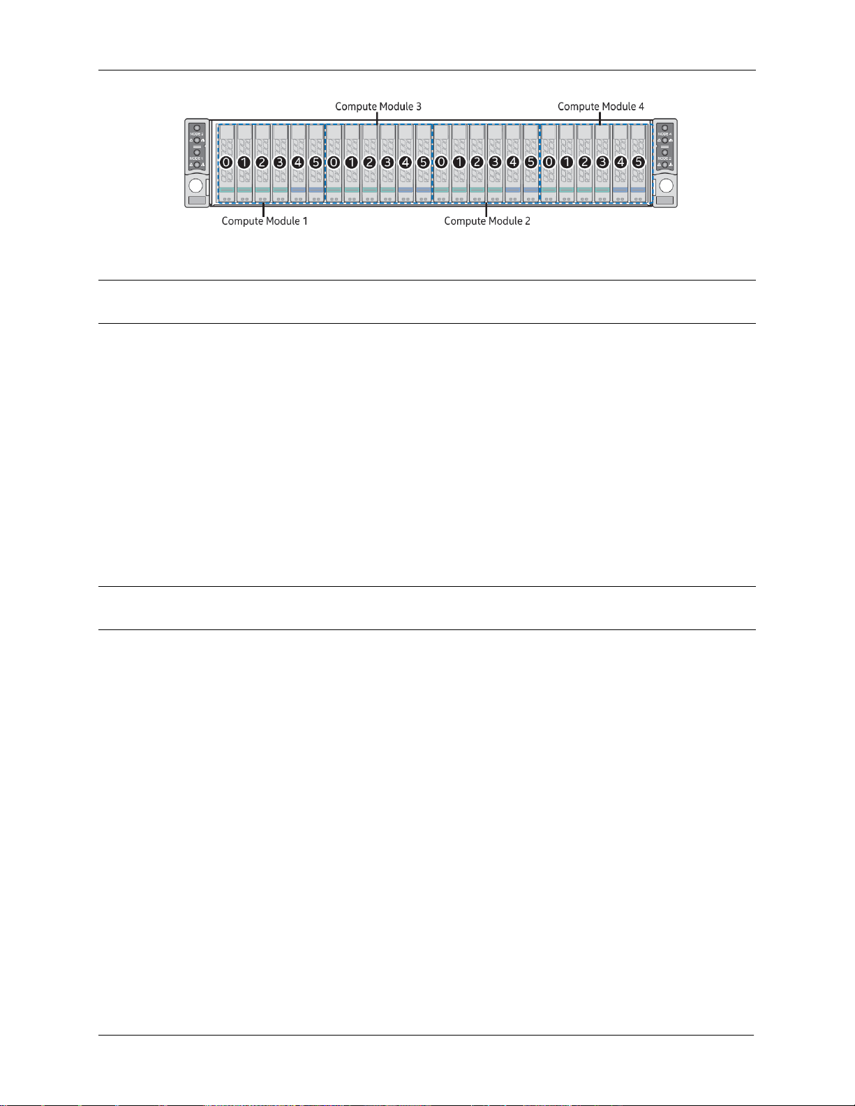
Intel® Server Chassis H2000G Product Family TPS Drive Support
39
Figure 24. 24 x 2.5” Drive Configuration
Note: Replace the faulty drive only with one from the same manufacturer with the same model
and capacity.
For 24 x 2.5” drive configuration, the drive bay is capable of supporting 12 Gbps SAS or
6 Gbps SAS drives. The SAS drives are hot-swappable. The front side of the backplane
includes 24 drive interface connectors. All the 24 connectors can support SAS drives,
but only the connector #4 and #5 of each compute module are capable of supporting
PCIe* SFF devices.
PCIe* SFF (NVME) SSDs are hot swap / hot plug capable. Support and usage models
are OS dependent.
For a given compute module, any combination of PCIe* SFF devices and SAS devices
can be supported, as long as the number of PCIe* SFF devices does not exceed two
and they are installed into any of the last two drive connectors on the backplane and
the remaining drives are SAS drive.
Note: Mixing of PCIe* SFF and SAS devices in an alternating manner is not a recommended
configuration.
Revision 2.21
Page 52

Drive Support Intel® Server Chassis H2000G Product Family TPS
40
5.2 Drive Carrier
Each SATA/SAS hard drive or SSD installed into a backplane is mounted to a hot-swap drive
carrier. Drive carriers include a latching mechanism used to assist with drive extraction and
drive insertion. There are drive trays to support 2.5” devices and 3.5” devices.
There are three types of drive carrier:
3.5" drive carrier (shipped in H2312XXKR2/LR2)
2.5" drive carrier (shipped in H2216XXKR2/LR2 and H2224XXKR2/LR2)
2.5" drive/PCIe* SFF device carrier (shipped in H2224XXKR2/LR2)
Figure 25. 3.5" Drive Carrier Overview
Figure 26. 2.5" Drive Carrier Overview
Revision 2.21
Page 53
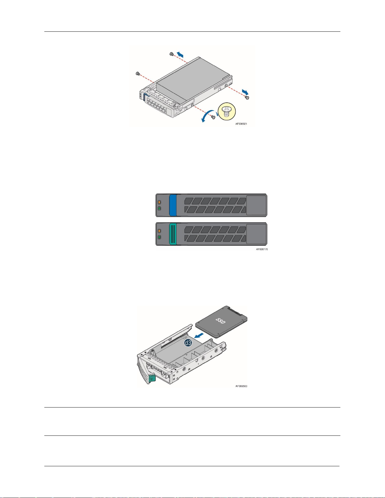
Intel® Server Chassis H2000G Product Family TPS Drive Support
41
Figure 27. 2.5" Drive/PCIe* SFF Device Carrier Overview
For H2224XXKR2 and H2224XXLR2, two different drive carriers are included in the drive bay.
Drive carriers with a Blue latch are used to identify support of PCIe* SFF devices or SAS drives.
Drives carriers with a Green latch are used to identify support of SAS drives only.
Figure 28. Combo Backplane Kit Device Carrier Identification
To maintain system thermals, all drive bays must be populated with a drive carrier mounted
with a hard disk drive, SSD, or supplied drive blank. Drive blanks used with the 3.5” drive tray
can also be used to mount a 2.5” SSD into it as shown below.
Figure 29. 3.5" Drive Carrier Support 2.5” SSD
Note: Due to degraded performance and reliability concerns, the use of the 3.5” drive blank as
a 2.5” device bracket is intended to support SSD type storage devices only. Installing a 2.5”
hard disk drive into the 3.5” drive blank is not supported.
Revision 2.21
Page 54

Drive Support Intel® Server Chassis H2000G Product Family TPS
42
5.3 Hot-Swap Drive Support
The Intel® Server Chassis H2000G product family supports hot-swap SATA/SAS drives. Drives
interface with the passive backplane through a blind mate connection when drives are
installed into a drive bay using hot-swap drive carriers.
Each compute module has dedicated Hot Swap Controller (HSC) to manage three or four
drives. There are totally four sets of independent Programmable System On Chip (PSOC) on
the backplane, to function as HSC respectively to four compute modules.
The following sections describe the feature and connections between the backplane and
server board.
5.3.1 Backplane Feature Set
H2312XXKR2/LR2: 12x SAS/SATA 3.5" drives at 12 Gbps SAS and 6 Gbps SATA or
slower speeds, divided into four groups of three hot-swap drives. Each drive group is
associated with one of the four compute modules respectively in the 2U chassis.
H2216XXKR2/LR2: 16x SAS/SATA 2.5" drives at 12 Gbps SAS and 6 Gbps SATA or
slower speeds, divided into four groups of four hot-swap drives. Each DRIVE group is
associated with one of the four compute modules respectively in the 2U chassis.
H2224XXKR2/LR2: 24 x SAS 2.5" drives at 12 Gbps SAS or slower speeds, divided into
four groups of six hot-swap drives. Each drive group is associated with one of the four
compute modules respectively in the 2U chassis.
One SGPIO SFF-8485 interface per each of the compute module total of four SGPIO on
the backplane.
Three SMBus interfaces supported on this HSBP:
- SMBus R1: For chassis Temp Sensor and Chassis FRU EEPROM device
- SMBus R5: Connectivity up to two HSBP controllers
- SMBus R7: Connectivity up to two common redundant power supply (CRPS)
module PMBus
Two front panel connectors; each FP connector provides signals for two compute
modules.
FRU EEPROM support through external device.
In-application Microcontroller FW updateable over I2C interface. No special hardware
needed for field FW upgrade when used with EPSD Baseboard with BMC support.
Drive Status LED and Activity LED; four of each per compute module.
Drive Presence detect inputs to the Microcontroller; four of each per compute module.
5V_MAIN VR (switcher regulator) from P12V_MAIN and 5V_AUX VR (switcher regulator)
from P12V_STBY for drive power and for the compute modules. This HSBP is intended
to be used with 12V only main power subsystems.
Revision 2.21
Page 55

Intel® Server Chassis H2000G Product Family TPS Drive Support
43
A
SATA/SAS connectors for Compute Module 1
B
SATA/SAS connectors for Compute Module 2
C
SATA/SAS connectors for Compute Module 3
D
SATA/SAS connectors for Compute Module 4
5.3.2 3.5" Hot Swap Backplane Connector Scheme
The following diagrams show the layout of major components and connectors for 3.5" Hot
Swap backplane.
Figure 30. 3.5" Backplane Component and Connectors (Front View)
Revision 2.21
Page 56

Drive Support Intel® Server Chassis H2000G Product Family TPS
44
A
2-blade compute module power connector for compute module 4
B
2x40 pin bridge board connector for compute module 4
C
2x8 pin power supply input connector
D
2x8 pin power supply input connector
E
2x7 pin power control cable connector
F
2-blade compute module power connector for compute module 3
G
2x40 pin bridge board connector for compute module 3
H
2x40 pin bridge board connector for compute module 1
I
20-pin front panel cable connector for compute module 1, 3
J
2-blade compute module power connector for compute module 1
K
2x8 pin power supply input connector
L
2x8 pin power supply input connector
M
2x40 pin bridge board connector for compute module 2
N
2-blade compute module power connector for compute module 2
O
20-pin front panel cable connector for compute module 2, 4
Figure 31. 3.5" Backplane Component and Connectors (Back View)
Revision 2.21
Page 57
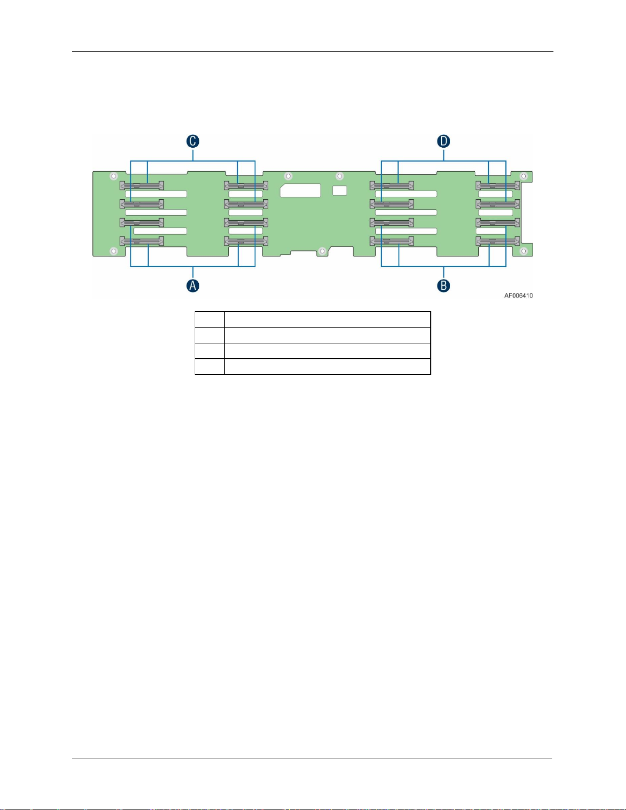
Intel® Server Chassis H2000G Product Family TPS Drive Support
45
A
SATA/SAS connectors for Compute Module 1
B
SATA/SAS connectors for Compute Module 2
C
SATA/SAS connectors for Compute Module 3
D
SATA/SAS connectors for Compute Module 4
5.3.3 2.5" Hot Swap Backplane Connector Scheme
The following diagrams show the layout of major components and connectors for 2.5" Hot
Swap backplane.
Figure 32. 2.5" Backplane Component and Connectors (Front View)
Revision 2.21
Page 58
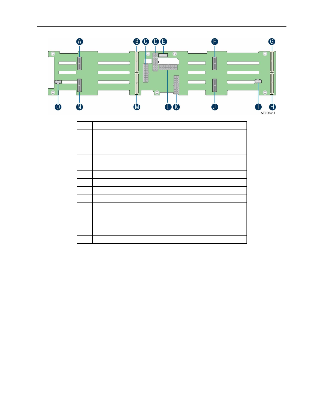
Drive Support Intel® Server Chassis H2000G Product Family TPS
46
A
2-Blade Compute Module Power connector for Compute Module 4
B
2x40 pin Bridge Board connector for Compute Module 4
C
2x8 pin Power supply input connector
D
2x7 pin Power Control cable connector
E
2x8 pin Power supply input connector
F
2-Blade Compute Module Power connector for Compute Module 3
G
2x40 pin Bridge Board connector for Compute Module 3
H
2x40 pin Bridge Board connector for Compute Module 1
I
20-pin Front Panel cable connector for Compute Module 1, 3
J
2-Blade Compute Module Power connector for Compute Module 1
K
2x8 pin Power supply input connector
L
2x8 pin Power supply input connector
M
2x40 pin Bridge Board connector for Compute Module 2
N
2-Blade Compute Module Power connector for Compute Module 2
O
20-pin Front Panel cable connector for Compute Module 2, 4
Figure 33. 2.5" Backplane Component and Connectors (Back View)
Revision 2.21
Page 59

Intel® Server Chassis H2000G Product Family TPS Drive Support
47
A
SAS 0-3 SFF-8680 connectors (Compute Module 1)
B
SAS 4-5 / PCIe* SFF 0-1 SFF-8639 connectors (Compute Module 1)
C
SAS 6-9 SFF-8680 connectors (Compute Module 3)
D
SAS 10-11 / PCIe* SFF 2-3 SFF-8639 connectors (Compute Module 3)
E
SAS 12-15 SFF-8680 connectors (Compute Module 2)
F
SAS 16-17 / PCIe* SFF 4-5 SFF-8639 connectors (Compute Module 2)
G
SAS 18-21 SFF-8680 connectors (Compute Module 4)
H
SAS 22-23 / PCIe* SFF 6-7 SFF-8639 connectors (Compute Module 4)
5.3.4 SAS/PCIe* SFF Combo 24 x 2.5" Hot Swap Backplane
The SAS/PCIe* SFF combo 24 x 2.5" hot swap backplane is capable of supporting a
combination of both SAS hard drives, SAS SSDs, and up to eight PCIe* SFF (Small Form Factor)
(NVMe) devices. The following diagrams show the layout of major components and
connectors for 2.5" Hot Swap backplane.
Figure 34. 24 x 2.5" Backplane Component and Connectors (Front View)
Revision 2.21
Page 60
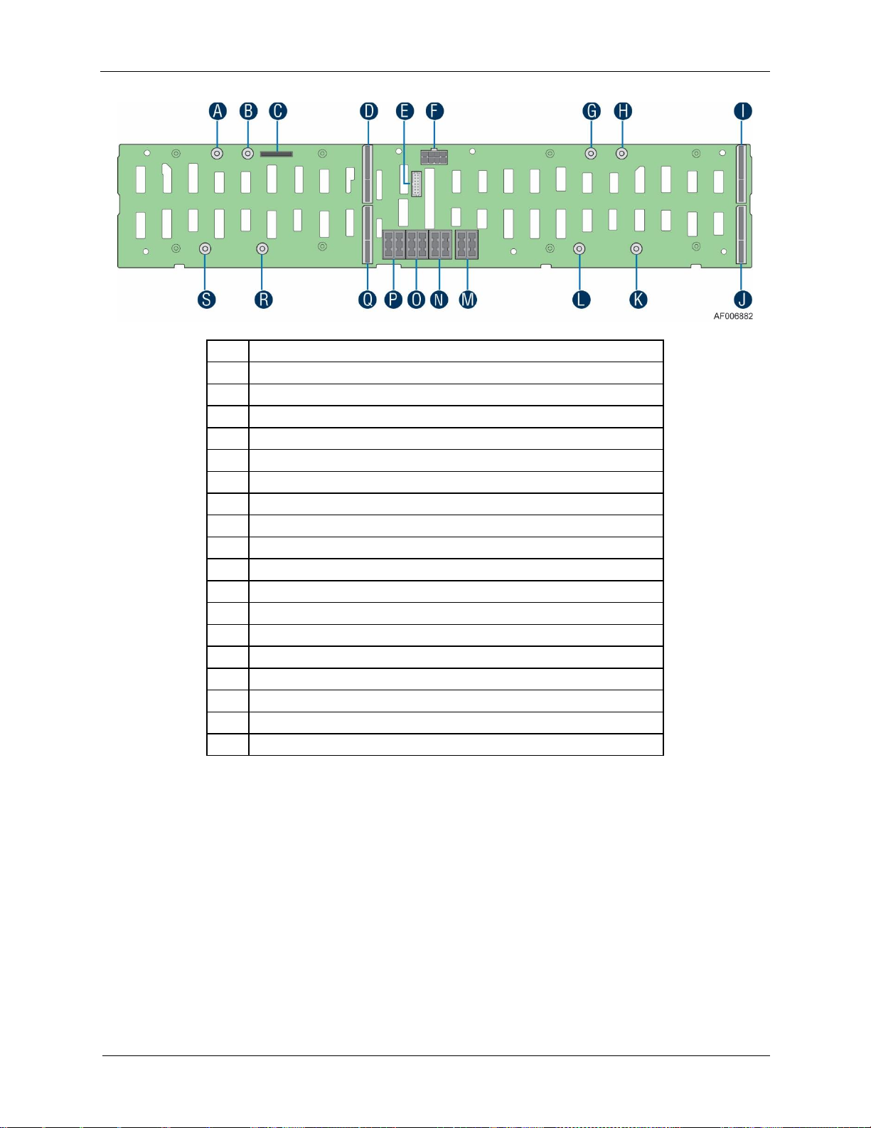
Drive Support Intel® Server Chassis H2000G Product Family TPS
48
A
Power Mate Pin (to BIB)
B
Power Mate Pin (to BIB)
C
80 pin Misc Signal Connector (to BIB)
D
100 pin bridge board connector
E
2x7 pin power control cable connector (to PDB)
F
2x4 pin P5V power cable connector (to PIB)
G
Power Mate Pin (to BIB)
H
Power Mate Pin (to BIB)
I
100 pin bridge board connector
J
100 pin bridge board connector
K
Power Mate Pin (to BIB)
L
Power Mate Pin (to BIB)
M
12V power connector (to PIB)
N
12V power connector (to PIB)
O
12V power connector (to PIB)
P
12V power connector (to PIB)
Q
100 pin bridge board connector
R
Power Mate Pin (to BIB)
S
Power Mate Pin (to BIB)
Figure 35. 24 x 2.5" Backplane Component and Connectors (Back View)
5.3.5 Backplane Interposer Board
The backplane interposer board (BIB) is only used in 24 x 2.5” drive chassis as the interposer
between the backplane and the power docking board to connect the power and
miscellaneous (misc.) signals from the backplane to the compute modules. Two backplane
interposer boards are pre-assembled with the 24 x 2.5” drive backplane in the server chassis
to support four compute modules.
The BIB is a completely passive board, which contains connectors on both sides of the board
to connect to the backplane on the front side and the power docking board on the back side.
Revision 2.21
Page 61
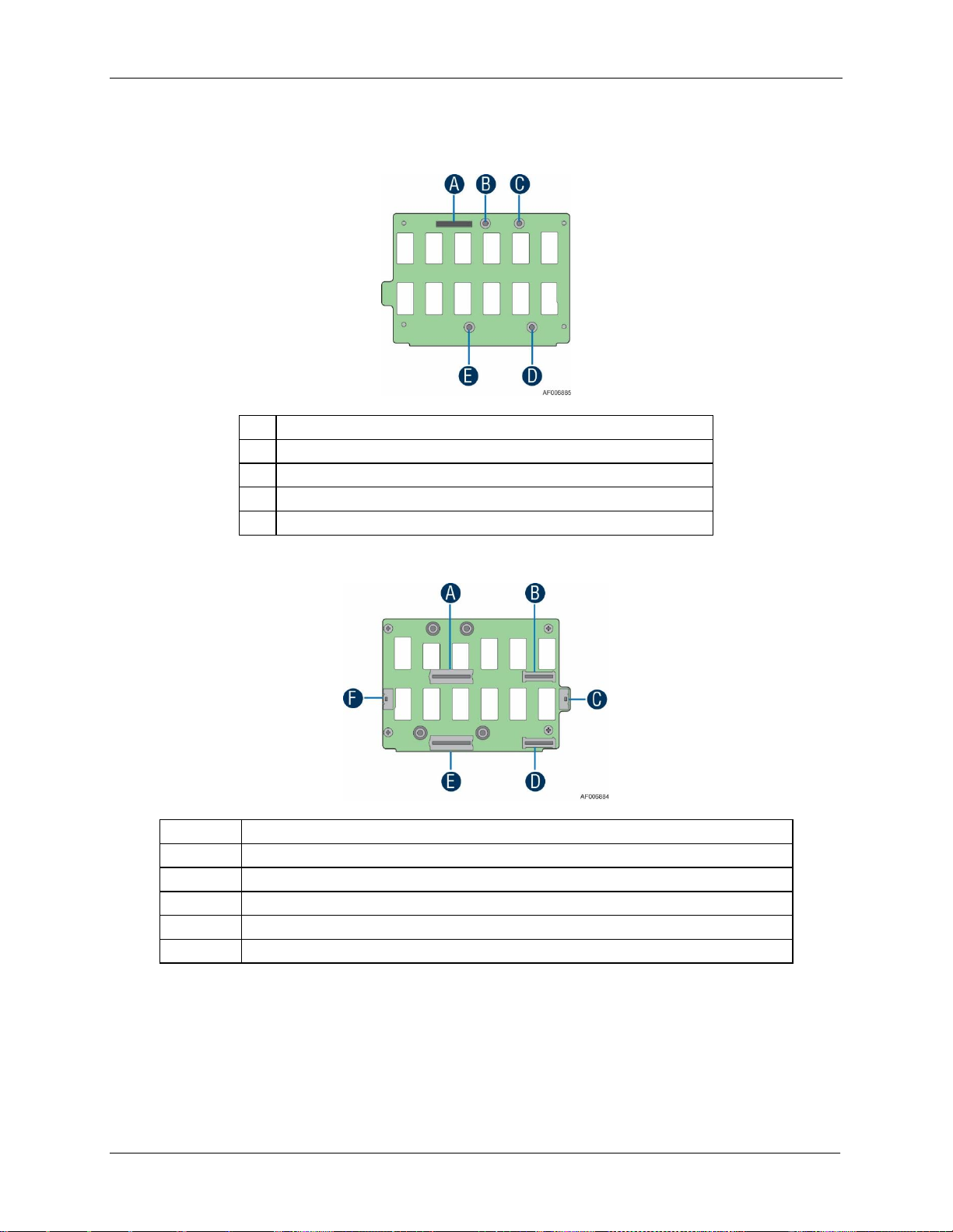
Intel® Server Chassis H2000G Product Family TPS Drive Support
49
A
80 pin Misc Signal Connector (to backplane)
B
Power Mate Pin Hole (to backplane)
C
Power Mate Pin Hole (to backplane)
D
Power Mate Pin Hole (to backplane)
E
Power Mate Pin Hole (to backplane)
A
Power Edge Connector (to top compute module power docking board)
B
40 pin Misc. Signal Connector (to top compute module power docking board)
C
Front Panel Connector
D
40 pin Misc. Signal Connector (to bottom compute module power docking board)
E
Power Edge Connector (to bottom compute module power docking board)
F
Front Panel Connector
Two front panel connectors with the same signals routed are placed on the BIB for easy of
cabling to the front panel on each side of the chassis.
Figure 36. Backplane Interposer Board Front View
Figure 37. Backplane Interposer Board Back View
5.3.6 Backplane LED Support
Each drive tray includes separate LED indicators for drive Activity and drive Status. Light pipes
integrated into the drive tray assembly direct light emitted from LEDs mounted next to each
Revision 2.21
Page 62
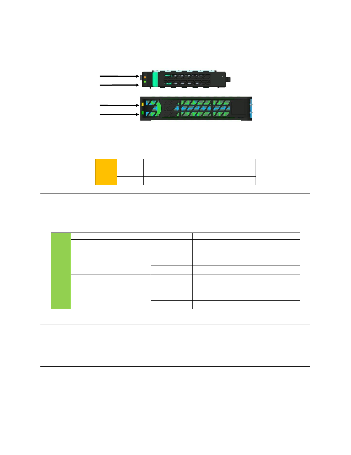
Drive Support Intel® Server Chassis H2000G Product Family TPS
50
Amber
Off
No access and no fault
Solid On
Hard Drive Fault has occurred
Blink
RAID rebuild in progress (1 Hz), Identify (2 Hz)
Green
Condition
Drive Type
Behavior
Power on with no drive activity
SAS/PCIe SFF
LED stays on
SATA
LED stays off
Power on with drive activity
SAS/PCIe SFF
LED blinks off when processing a command
SATA
LED blinks on when processing a command
Power on and drive spun down
SAS/PCIe SFF
LED stays off
SATA
LED stays off
Power on and drive spinning up
SAS
LED blinks
SATA/PCIe SFF
LED stays off
Amber Status LED
Green Activity LED
2.5” drive tray
Amber Status LED
Green Activity LED
3.5” drive tray
drive connector on the backplane to the drive tray faceplate, making them visible from the
front of the system.
Figure 38. Drive Tray LED Identification
Table 33. Drive Status LED States
Note: With Intel® Compute Module HNS2600TP Product Family, the drive status LED only
supports SAS/SATA hard drives or SSDs. It stays off for PCIe* SFF devices.
Table 34. Drive Activity LED States
Note: The drive activity LED is driven by signals coming from the drive itself. Drive vendors may
choose to operate the activity LED differently from what is described in the table above. Should
the activity LED on a given drive type behave differently than what is described, customers
should reference the drive vendor specifications for the specific drive model to determine what
the expected drive activity LED operation should be.
5.3.7 Backplane Connector Definition
The backplanes include several different connectors. This section defines the purpose and
pin-out associated with each connector.
Revision 2.21
Page 63
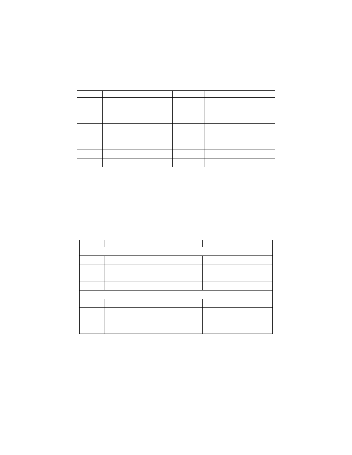
Intel® Server Chassis H2000G Product Family TPS Drive Support
51
Pin
Signal Description
Pin
Signal Description
2
P12V_NODEx
1
GND
4
P12V_NODEx
3
GND
6
P12V_NODEx
5
GND
8
P12V_NODEx
7
GND
10
P12V_NODEx
9
GND
12
P12V_NODEx
11
GND
14
P12V_NODEx
13
GND
16
P12V_NODEx
15
GND
Pin
Signal Description
Pin
Signal Description
Lower Blade (Circuit 1)
1
GND
2
GND
3
GND
4
GND
5
GND
6
GND
7
GND
8
GND
Upper Blade (Circuit 2)
9
P12V
10
P12V
11
P12V
12
P12V
13
P12V
14
P12V
15
P12V
16
P12V
5.3.7.1 2x8 Pin Power Input Connector
The backplane is powered by +12V and +12V
from PDB of CRPS. The input power is
STB
distributed by backplane to all four compute modules.
Table 35. Backplane Input Power Connector Pin-out
Note: Each compute module has a separate power plane on backplane (P12V_NODEx).
5.3.7.2 2-Blade Compute Module Power Connector
The backplane provides main power to compute module through 2-Blade power connector.
Table 36. 2-Blade Compute Module Power Connector Pin-out
Revision 2.21
Page 64

Drive Support Intel® Server Chassis H2000G Product Family TPS
52
Pin
Signal Description
Pin
Signal Description
1
5V_AUX
2
5V_AUX
3
SATA0_TXN
4
USB2_OC
5
SATA0_TXP
6
GND
7
GND
8
SATA0_RXN
9
NODE_Present_N (GND)
10
SATA0_RXP
11
ALL_NODE_OFF
12
GND
13
spare
14
USB2_P0P
15
GND
16
USB2_P0N
17
IPMB-Data
18
GND
19
IPMB-Clk
20
FP HDD_ACT_LED_N
21
GND
22
FP Activity LED_N
23
SMBUS_R1 DATA
24
FP Health LEDA_N
25
SMBUS_R1 CLK
26
FP Health LEDG_N
27
GND
28
FP PWR LED_N
29
SMBUS_R5 DATA
30
FP ID LED_N
31
SMBUS_R5 CLK
32
FP ID BTN_N
33
GND
34
FP RST BTN_N
35
SMBUS_R7 DATA
36
FP PWR BTN_N
37
SMBUS_R7 CLK
38
FP NMI BTN_N
39
GND
40
SPA_SOUT_N
41
PMBUS Alert_N
42
SPA_SIN_N
43
NODEx_ON_N
44
ID3
45
SGPIO DATA IN
46
ID2
47
SGPIO Data Out
48
ID1
49
SGPIO LD
50
ID0
51
SPKR
52
SGPIO CLK
53
GND
54
GND
55
SAS3_RX
56
SAS3_TX
57
SAS3_RX
58
SAS3_TX
59
GND
60
GND
61
SAS2_TX
62
SAS2_RX
63
SAS2_TX
64
SAS2_RX
65
GND
66
GND
67
SAS1_RX
68
SAS1_TX
69
SAS1_RX
70
SAS1_TX
71
GND
72
GND
5.3.7.3 2x40 Pin Bridge Board Connector
The compute module provides four SATA/SAS ports to backplane, together with front panel
control signals and SMBus.
Table 37. 2x40 Pin Connector Pin-out for Compute Module Bridge Board
Revision 2.21
Page 65

Intel® Server Chassis H2000G Product Family TPS Drive Support
53
Pin
Signal Description
Pin
Signal Description
73
SAS0_TX
74
SAS0_RX
75
SAS0_TX
76
SAS0_RX
77
GND
78
GND
79
3.3V
80
3.3V
Pin
Signal Description
1
GND
2
FP1_PWR_BTN_N
3
FP1_RST_BTN_N
4
FP1_ID_BTN_N
5
P5VSB
6
FP1_PWR_LED_N
7
FP1_HEALTH_LEDG_N
8
FP1_HEALTH_LEDA_N
9
FP1_ACTIVITY_LED_N
10
FP1_ID_LED_N
11
GND
12
FP2_PWR_BTN_N
13
FP2_RST_BTN_N
14
FP2_ID_BTN_N
15
P3V3SB
16
FP2_PWR_LED_N
17
FP2_HEALTH_LEDG_N
18
FP2_HEALTH_LEDA_N
19
FP2_ACTIVITY_LED_N
20
FP2_ID_LED_N
Pin
Signal Description
Pin
Signal Description
1
SMBUS_R7_DATA
2
A0
5.3.7.4 20-Pin Front Panel Connector
The backplanes provide connectors for front panel control signals. Each connector integrates
the control signals of two compute modules.
Table 38. Front Panel Connector Pin-out
5.3.7.5 2x7 Pin Power Supply Control Signal Connector
The backplanes provide power supply control signals, together with PMBus functionality
integrated.
Revision 2.21
Table 39. Power Supply Control Connector Pin-out
Page 66

Drive Support Intel® Server Chassis H2000G Product Family TPS
54
Pin
Signal Description
Pin
Signal Description
3
SMBUS_R7_CLK
4
PSON_N
5
PMBUS_ALERT_N
6
12V RS_RTN
7
PWROK
8
12V RS
9
Reserved
10
PDU1-12VSB
11
PDU1-12VSB
12
PDU2-12VSB
13
PDU2-12VSB
14
Reserved
Pin
Signal Description
Pin
Signal Description
1
N1_PE_SMB_CLK
2
N1_PE_SMB_DATA
3
GND
4
N1_FM_ALL_NODE_OFF
5
P5V_STBY
6
GND
7
GND
8
N1_SMB_IPMB_5VSTBY_BP_DATA
9
P3V3_STBY
10
N1_SMB_IPMB_5VSTBY_BP_CLK
11
Reserve
12
GND
13
Reserve
14
N1_SMB_SENSOR_3V3STBY_BP_DATA
15
Reserve
16
N1_SMB_SENSOR_3V3STBY_BP_CLK
17
Reserve
18
GND
19
Reserve
20
N1_SMB_HSBP_3V3_BP_DATA
21
Reserve
22
N1_SMB_HSBP_3V3_BP_CLK
23
N1_FM_IBMC_NODEID_1
24
GND
25
N1_FM_IBMC_NODEID_0
26
N1_SMB_PMBUS_BP_DATA
27
GND
28
N1_SMB_PMBUS_BP_CLK
29
N1_SGPIO_SAS12G_1_CLOCK_R1
30
GND
31
GND
32
N1_IRQ_SML1_PMBUS_ALERT_N
33
N1_SGPIO_SAS12G_0_CLK
34
N1_FM_NODE_ON_N
35
N1_SGPIO_SAS12G_0_LD
36
N1_SGPIO_SAS12G_1_DATAIN1_R1
37
N1_SGPIO_SAS12G_0_Data_Out
38
N1_SGPIO_SAS12G_1_DATAOUT0_R1
39
N1_PWROK
40
N1_SGPIO_SAS12G_1_LOAD_R1
41
PE_SMB_CLK
42
PE_SMB_DATA
43
GND
44
FM_ALL_NODE_OFF
45
Reserve
46
GND
47
Reserve
48
SMB_IPMB_5VSTBY_BP_DATA
49
Reserve
50
SMB_IPMB_5VSTBY_BP_CLK
51
Reserve
52
GND
53
Reserve
54
SMB_SENSOR_3V3STBY_BP_DATA
55
Reserve
56
SMB_SENSOR_3V3STBY_BP_CLK
57
Reserve
58
GND
5.3.8 Backplane Interposer Board Connectors
Table 40. 80 pin Misc. Signal Connector
Revision 2.21
Page 67

Intel® Server Chassis H2000G Product Family TPS Drive Support
55
Pin
Signal Description
Pin
Signal Description
59
Reserve
60
SMB_HSBP_3V3_BP_DATA
61
Reserve
62
SMB_HSBP_3V3_BP_CLK
63
FM_IBMC_NODEID_1
64
GND
65
FM_IBMC_NODEID_0
66
SMB_PMBUS_BP_DATA
67
GND
68
SMB_PMBUS_BP_CLK
69
SGPIO_SAS12G_1_CLOCK_R1
70
GND
71
GND
72
IRQ_SML1_PMBUS_ALERT_N
73
SGPIO_SAS12G_0_CLK
74
FM_NODE_ON_N
75
SGPIO_SAS12G_0_LD
76
SGPIO_SAS12G_1_DATAIN1_R1
77
SGPIO_SAS12G_0_Data_Out
78
SGPIO_SAS12G_1_DATAOUT0_R1
79
PWROK
80
SGPIO_SAS12G_1_LOAD_R1
Pin
Signal Description
Pin
Signal Description
1
PE_SMB_CLK
2
PE_SMB_DATA
3
GND
4
FM_ALL_NODE_OFF
5
FP HDD_ACT_LED_N
6
GND
7
FP Activity LED_N
8
SMB_IPMB_5VSTBY_BP_DATA
9
FP Health LEDA_N
10
SMB_IPMB_5VSTBY_BP_CLK
11
FP Health LEDG_N
12
GND
13
FP_PWR_LED_BUF_R_N
14
SMB_SENSOR_3V3STBY_BP_DATA
15
FP_ID_LED_BUF_R_N
16
SMB_SENSOR_3V3STBY_BP_CLK
17
FP_ID_BTN_R_N
18
GND
19
FP_RST_BTN_R_N
20
SMB_HSBP_3V3_BP_DATA
21
FP_PWR_BTN_R_N
22
SMB_HSBP_3V3_BP_CLK
23
FM_IBMC_NODEID_1
24
GND
25
FM_IBMC_NODEID_0
26
SMB_PMBUS_BP_DATA
27
GND
28
SMB_PMBUS_BP_CLK
29
SGPIO_SAS12G_1_CLOCK_R1
30
GND
31
GND
32
IRQ_SML1_PMBUS_ALERT_N
33
SGPIO_SAS12G_0_CLK
34
FM_NODE_ON_N
35
SGPIO_SAS12G_0_LD
36
SGPIO_SAS12G_1_DATAIN1_R1
37
SGPIO_SAS12G_0_Data_Out
38
SGPIO_SAS12G_1_DATAOUT0_R1
39
PWROK
40
SGPIO_SAS12G_1_LOAD_R1
Table 41. 40 pin Misc. Signal Connector
Revision 2.21
Page 68

Drive Support Intel® Server Chassis H2000G Product Family TPS
56
Pin
Signal Description
Pin
Signal Description
1
P12V
2
P12V
3
P12V
4
P12V
5
P12V
6
P12V
7
P12V
8
P12V
9
P12V
10
P12V
11
GND
12
GND
13
GND
14
GND
15
GND
16
GND
17
GND
18
GND
19
GND
20
GND
Pin
Signal Description
Pin
Signal Description
1
GND
2
FP_PORTx_PWR_BTN_N
3
FP_PORTx_RST_BTN_N
4
FP_PORTx_ID_BTN_N
5
P5V_AUX
6
FP_PORTx_PWR_LED_N
7
FP_PORTx_HEALTH_LEDG_N
8
FP_PORTx_HEALTH_LEDA_N
9
FP_PORTx_ACT_LED_N
10
FP_PORTx_ID_LED_N
11
GND
12
FP_PORTy_PWR_BTN_N
13
FP_PORTy_RST_BTN_N
14
FP_PORTy_ID_BTN_N
15
P3V3_AUX
16
FP_PORTy_PWR_LED_N
17
FP_PORTy_HEALTH_LEDG_N
18
FP_PORTy_HEALTH_LEDA_N
19
FP_PORTy_ACT_LED_N
20
FP_PORTy_ID_LED_N
Table 42. BIB Power Edge Connector
Table 43. Front Panel Connector
Revision 2.21
Page 69

Intel® Server Chassis H2000G Product Family TPS Front Panel Control and Indicators
57
Feature
Function
Power Button with Power LED
Toggles the compute module power on/off. This button also integrates
the power LED.
Compute Module ID Button
with ID LED
Toggles between ID LED on and off.
6. Front Panel Control and Indicators
The Intel® Server Chassis H2000G product family Front Control Panel is integrated with rack
handles at the both sides of the chassis. Each control panel contains two sets of compute
module control buttons and status LEDs. The control panel assembly is pre-assembled and
fixed with the rack handles.
Figure 39. Front Control Panel
6.1 Control Panel Button
The following table lists the control panel features and functions. The control panel features a
compute module power button.
Table 44. Front Control Button Function
Revision 2.21
Page 70

Front Panel Control and Indicators Intel® Server Chassis H2000G Product Family TPS
58
LED Indicator
Color
Condition
What it describes
Power
Green
On
Power On/ACPI S0 state
Green
Blink
Sleep/ACPI S1 state
-
Off
Power Off /ACPI S5 state
LAN (i350 Dual NIC)
Green
On
LAN Link no Access
Green
Blink
LAN Activity
-
Off
No Link
Compute Module
Status
Green
On
Compute Module Ready/No Alarm
Green
Blink
Compute Module ready, but degraded: redundancy
lost such as the power supply or fan failure; noncritical temp/voltage threshold; battery failure; or
predictive power supply failure.
Amber
On
Critical Alarm: Critical power modules failure,
critical fans failure, voltage (power supply), critical
temperature and voltage
Amber
Blink
Non-Critical Alarm: Redundant fan failure,
redundant power module failure, non-critical
temperature and voltage
-
Off
Power off: Compute Module unplugged
Power on: Compute Module powered off and in
standby, no prior degraded\non-critical\critical
state
State
Power Mode
LED
Description
Power Off
Non-ACPI
Off
Compute module power is off and the BIOS has not initialized
the chipset.
6.2 Control Panel LED Indicators
The control panel houses independent two LEDs and two button integrated LEDs for each
compute module, which are viewable to display the compute module’s operating status. The
following table identifies each LED and describes their functionality.
Table 45. Front LED Indicator Functions
Notes:
1. Blink rate is ~1 Hz at 50% duty cycle.
2. It is also off when the compute module is powered off (S5) or in a sleep state (S1).
3. The power LED sleep indication is maintained on standby by the chipset. If the compute module is
powered down without going through the BIOS, the LED state in effect at the time of power off is restored
when the compute module is powered on until the BIOS clear it.
4. If the compute module is not powered down normally, it is possible the Power LED will blink at the same
time the compute module status LED is off due to a failure or configuration change that prevents the BIOS
from running.
6.2.1 Power LED
Table 46. Power LED Operation
Revision 2.21
Page 71

Intel® Server Chassis H2000G Product Family TPS Front Panel Control and Indicators
59
State
Power Mode
LED
Description
Power On
Non-ACPI
Solid On
Compute module power is on but the BIOS has not yet initialized
the chipset.
S5
ACPI
Off
Mechanical is off and the operating system has not saved any
context to the drive.
S1 Sleep
ACPI
Blink
DC power is still on. The operating system has saved context and
gone into a level of low-power state.
S0
ACPI
Solid On
Compute module and the operating system are up and running.
Color
State
Criticality
Description
Off
System is
not
operating
Not ready
System is powered off (AC and/or DC).
System is in EuP Lot6 Off Mode.
System is in S5 Soft-Off State.
Green
Solid on
Ok
Indicates that the System is running (in S0 State) and its
status is ‘Healthy’. The system is not exhibiting any
errors. AC power is present and BMC has booted and
manageability functionality is up and running.
After a BMC reset, and in conjunction with the Chassis ID
solid ON, the BMC is booting Linux*. Control has been
passed from BMC uBoot to BMC Linux* itself. It will be in
this state for ~10-~20 seconds.
Note: Blink rate is ~ 1Hz at 50% duty cycle.
6.2.2 Status LED
The control panel includes a bi-color Status LED. The Status LED on the control panel is tied
directly to the Status LED on the server board (if present). This LED indicates the current
health of the compute module. Possible LED states include solid green, blinking green,
blinking amber, and solid amber.
When the compute module is powered down (transitions to the DC-off state or S5), the BMC is
still on standby power and retains the sensor and front panel Status LED state established
before the power-down event.
When AC power is first applied to the compute module, the Status LED turns solid amber and
then immediately changes to blinking green to indicate that the BMC is booting. If the BMC
boot process completes with no errors, the Status LED will change to solid green.
When power is first applied to the compute module and 5V-STBY is present, the BMC
controller on the server board requires 15-20 seconds to initialize. During this time, the
compute module status LED will be solid on, both amber and green. Once BMC initialization
has completed, the status LED will stay green solid on. If power button is pressed before BMC
initialization completes, the compute module will not boot to POST.
Table 47. Status LED State Definitions
Revision 2.21
Page 72

Front Panel Control and Indicators Intel® Server Chassis H2000G Product Family TPS
60
Color
State
Criticality
Description
Green
~1 Hz blink
Degraded - system is
operating in a degraded
state although still
functional, or system is
operating in a redundant
state but with an
impending failure warning
System degraded:
Redundancy loss such as power-supply or fan.
Applies only if the associated platform sub-system
has redundancy capabilities.
Fan warning or failure when the number of fully
operational fans is less than minimum number
needed to cool the system.
Non-critical threshold crossed – Temperature
(including HSBP temp), voltage, input power to
power supply, output current for main power rail
from power supply and Processor Thermal Control
(Therm Ctrl) sensors.
Power supply predictive failure occurred while
redundant power supply configuration was present.
Unable to use all of the installed memory (more
than 1 DIMM installed).
Correctable Errors over a threshold and migrating to
a spare DIMM (memory sparing). This indicates that
the system no longer has spared DIMMs (a
redundancy lost condition). Corresponding DIMM
LED lit.
In mirrored configuration, when memory mirroring
takes place and system loses memory redundancy.
Battery failure.
BMC executing in uBoot. (Indicated by Chassis ID
blinking at 3Hz). System in degraded state (no
manageability). BMC uBoot is running but has not
transferred control to BMC Linux*. Server will be in
this state 6-8 seconds after BMC reset while it pulls
the Linux* image into flash.
BMC Watchdog has reset the BMC.
Power Unit sensor offset for configuration error is
asserted.
HDD HSC is off-line or degraded.
Amber
~1 Hz blink
Non-critical - System is
operating in a degraded
state with an impending
failure warning, although
still functioning
Non-fatal alarm – system is likely to fail:
Critical threshold crossed – Voltage, temperature
(including HSBP temp), input power to power
supply, output current for main power rail from
power supply and PROCHOT (Therm Ctrl) sensors.
VRD Hot asserted.
Minimum number of fans to cool the system not
present or failed
Hard drive fault
Power Unit Redundancy sensor – Insufficient
resources offset (indicates not enough power
supplies present)
In non-sparing and non-mirroring mode if the
threshold of correctable errors is crossed within the
window
Revision 2.21
Page 73

Intel® Server Chassis H2000G Product Family TPS Front Panel Control and Indicators
61
Color
State
Criticality
Description
Amber
Solid on
Critical, non-recoverable –
System is halted
Fatal alarm – system has failed or shut down:
CPU CATERR signal asserted
MSID mismatch detected (CATERR also asserts for
this case).
CPU 1 is missing
CPU Thermal Trip
No power good – power fault
DIMM failure when there is only 1 DIMM present and
hence no good memory present.
Runtime memory uncorrectable error in non-
redundant mode.
DIMM Thermal Trip or equivalent
SSB Thermal Trip or equivalent
CPU ERR2 signal asserted
BMC/Video memory test failed. (Chassis ID shows
blue/solid-on for this condition)
Both uBoot BMC FW images are bad. (Chassis ID
shows blue/solid-on for this condition)
240VA fault
Fatal Error in processor initialization:
- Processor family not identical
- Processor model not identical
- Processor core/thread counts not identical
- Processor cache size not identical
- Unable to synchronize processor frequency
- Unable to synchronize QPI link frequency
Uncorrectable memory error in a non-redundant
mode
State
LED State
Identify active through button
Solid on
Identify active through command
~1 Hz blink
Off
Off
6.2.3 ID LED
The ID LED provides a visual indication of the server board or compute module being serviced.
The state of the ID LED is affected by the following:
Toggled by the ID button
Controlled by the Chassis Identify command (IPMI)
Revision 2.21
Table 48. ID LED
Page 74

Front Panel Control and Indicators Intel® Server Chassis H2000G Product Family TPS
62
There is no precedence or lock-out mechanism for the control sources. When a new request
arrives, all previous requests are terminated. For example, if the ID LED is blinking and the
chassis ID button is pressed, then the ID LED changes to solid on. If the button is pressed
again with no intervening commands, the ID LED turns off.
Revision 2.21
Page 75

Intel® Server Chassis H2000G Product Family TPS Appendix A: Integration and Usage Tips
63
Appendix A: Integration and Usage Tips
Before attempting to integrate and configure your chassis, you should reference this section,
which provides a list of useful information.
Remove the dummy tray cover before installing the compute module.
Install the dummy tray cover when respective compute module is plugged out.
Fans in the compute modules are not hot-swappable.
You must use the air duct to maintain compute module thermals.
To maintain system thermals, you must populate all drive bays with either a drive or
drive blank.
You must remove AC power from the compute module before service.
You can download the latest documentation, drivers, and software from the Intel Support
website at http://www.intel.com/support.
Revision 2.21
Page 76

Appendix B: Statement of Volatility Intel® Server Chassis H2000G Product Family TPS
64
Component Type
Size
Board Location
User Data
Name
Non-Volatile
256 Bytes
UM801
No
PSU Firmware
Non-Volatile
512 Bytes
U6N2
No
12 x 3.5” HSBP FRU
Non-Volatile
512 Bytes
U504
No
16 x 2.5” HSBP FRU
Non-Volatile
512 Bytes
U1A2
No
24 x 2.5” HSBP FRU
Appendix B: Statement of Volatility
This section describes the volatile and non-volatile components on the HSBP and Power
Supply Unit of the server chassis. It is not the intention of this document to include any
components not directly included in the server chassis, such as the server board, processors,
memory, drives, or add-in cards.
Chassis Board Components
The server chassis contains several components that can be used to store data. A list of
components for the HSBP and Power Supply Unit of the server chassis is included in the table
below. The sections below the table provide additional information about the fields in this
table.
Table 49. Non-volatile Components List
Component Type
Non-volatile: Non-volatile memory is persistent, and is not cleared when power is removed
from the chassis. Non-Volatile memory must be erased to clear data. The exact method of
clearing these areas varies by the specific component. Some areas are required for normal
operation of the server, and clearing these areas may render the server board inoperable.
Size
The size of each component includes sizes in bits, Kbits, bytes, kilobytes (KB) or megabytes
(MB).
Board Location
The physical location of each component is specified in the Board Location column. The board
location information corresponds to information on the board silkscreen.
User Data
The flash components on the server boards do not store user data from the operating system.
No operating system level data is retained in any listed components after AC power is
removed. The persistence of information written to each component is determined by its type
as described in the table.
Revision 2.21
Page 77

Intel® Server Chassis H2000G Product Family TPS Appendix C: System Configuration Table for Thermal Compatibility
Appendix C: System Configuration Table for Thermal Compatibility
This section provides system configuration compatibility data based on various supported system operating thermal limits. Two
tables are provided for each of the server board. The first table identifies supported system configurations while the system is in
“normal” operating mode; all systems fans are present, on-line, and operational. The second table identifies supported system
configurations while the system is in a “fan fail” mode; one system fan is no longer on-line or operational, fan redundancy is lost.
The following notes communicate support criteria associated with specific configurations identified in the following tables. Each
relevant note to a configuration is identified by reference number in the table.
"●" = Full Support without limitation
" " (Blank Cell) = Configuration Not supported
Thermal Configuration Tables – Intel® Server Board S2600KP Product Family
Notes:
1. 27°C is limited to elevations of 900m or less.
2. Quad Port IO Modules cannot be installed simultaneously with PCI Cards.
3. Processor - 135W - 4/6/8/16C, 120W-14C and 145W - 14/18C may have some performance impact.
4. Processors - There may be some performance impact during fan failures.
5. For A3/A4 individual PS selection:
1) For dual power supply configuration, power budget must fit within single power supply rated load and be installed in dual
configuration, or
2) For single power supply configuration, power budget must be sized with 30% margin to single power supply rated load.
6. When identifying memory in the table, only Rank and Width are required. Capacity is not required.
7. Processor limited to 120W to support 1.5W AOC cable. Processor limited to 120W and memory limited to DRx4 to support
2W AOC cable.
8. Supported with one HDD per node configuration.
9. Fan fail is not supported at A3/A4.
Revision 2.21 65
Page 78
Appendix C: System Configuration Table for Thermal Compatibility Intel® Server Chassis H2000G Product Family TPS
Intel® Server
Chassis
H2216XXKR2
Intel® Server Chassis
H2312XXKR2
ASHRAE (See
note 1)
Classifications
A2
A3
A4
27C
A2
A2
A3
A4 Max Ambient
35C
40C
45C
27C
35C
35C
40C
45C
<-- See note 1
PS (See note 5)
Power Supplies
See Note 5
See Note 5
EP Processors
(See notes 3
and 4)
EP, 135w, 12C (Intel® Xeon® processor E5-2690 V3)
●
● ● ●
<-- see note 4
EP, 120w, 12C (Intel® Xeon® processor E5-2680 V3, E5-2670
V3)
●
● ● ●
<-- see note 4
EP, 105w, 10C (Intel® Xeon® processor E5-2660 V3, E5-2650
V3)
● ● ●
● ●
●
<-- see note 4
EP, 90w, 8C (Intel® Xeon® processor E5-2640 V3)
● ● ● ● ● ● ●
<-- see note 4
EP, 85w,8C,6C (Intel® Xeon® processor E5-2630 V3, E5-2620 V3,
E5-2609 V3, E5-2603 V3)
● ● ● ● ● ● ●
●
<-- see note 4
EP, 135w, 8C,6C,4C (Intel® Xeon® processor E5-2667 V3, E52643 V3, E5-2637 V3)
●
● <-- see note 4
EP, 105w, 4C (Intel® Xeon® processor E5-2623 V3)
● ● ●
● ●
●
<-- see note 4
EP, 65w, 12C (Intel® Xeon® processor E5-2650L V3)
● ● ● ● ● ● ●
●
<-- See notes 3
and 4
EP, 55w, 8C (Intel® Xeon® processor E5-2630L V3)
● ● ● ● ● ● ●
●
<-- See notes 3
and 4
EP, 145w, 14C,18C (Intel® Xeon® processor E5-2697 V3, E52699 V3)
●
● <-- See notes 3
and 4
EP, 135w, 16C (Intel® Xeon® processor E5-2698 V3)
●
● <-- See notes 3
and 4
EP, 120w, 14C (Intel® Xeon® processor E5-2695 V3, E5-2683
V3)
●
● <-- See notes 3
and 4
Memory Type
(See note 6)
RDIMM-2Rx8,1Rx4
● ● ● ● ● ● ●
●
RDIMM-DRx4
● ● ● ● ● ● ●
●
LRDIMM-QRx4 DDP
● ● ● ● ● ● ●
Add-in Cards
(See note 2)
PCI Cards with 100LFM/55C spec
● ● ● ● ● ● ●
●
PCI Cards With 200LFM/55C spec
●
● ● ●
<-- See note 2
Table 50. Thermal Configuration Table – S2600KP Product Family, Normal Mode
66 Revision 2.21
Page 79
Intel® Server Chassis H2000G Product Family TPS Appendix C: System Configuration Table for Thermal Compatibility
Intel® Server
Chassis
H2216XXKR2
Intel® Server Chassis
H2312XXKR2
ASHRAE (See
note 1)
Classifications
A2
A3
A4
27C
A2
A2
A3
A4 Max Ambient
35C
40C
45C
27C
35C
35C
40C
45C
<-- See note 1
PCI Cards With 300LFM/55C spec
●
●
●
8
<-- See note 2
Module (See
note 2)
AXX10GBTWLIOM - Dual 10GBASE-T IO Module
● ● ● ● ● ● ●
●
AXX10GBNIAIOM - Dual SFP+ port 10GbE IO Module
● ● ● ● ● ● ●
●
AXX1FDRIBIOM - Single Port FDR Infiniband IO Module
● ● ● ● ● ● ●
●
AXX2FDRIBIOM - Dual Port FDR Infiniband IO Module
● ● ● ● ● ● ●
●
AXX4P1GBPWLIOM - Quad Port 1GbE IO Module
● ● ● ● ● ● ●
●
<-- See note 2
QSFP Cables
(See note 7)
Passive Cable
● ● ● ● ● ● ●
●
Active Optical Cable (1.5W)
●
●
●
7 Active Optical Cable (2W)
●
●
●
7
<-- See note 7
Intel® Server
Chassis
H2216XXKR2
Intel® Server
Chassis
H2312XXKR2
ASHRAE (See
note 1)
Classifications
A2
27C
A2
Max Ambient
35C
27C
35C
<-- See note 1
PS (See note 5)
Power Supplies
See Note 5
See Note 5
EP Processors
(See notes 3
and 4)
EP, 135w, 12C (Intel® Xeon® processor E5-2690 V3)
●
●
●
<-- see note 4
EP, 120w, 12C (Intel® Xeon® processor E5-2680 V3, E5-2670 V3)
●
●
●
<-- see note 4
EP, 105w, 10C (Intel® Xeon® processor E5-2660 V3, E5-2650 V3)
●
●
●
<-- see note 4
EP, 90w, 8C (Intel® Xeon® processor E5-2640 V3)
●
●
●
<-- see note 4
EP, 85w,8C,6C (Intel® Xeon® processor E5-2630 V3, E5-2620 V3, E5-2609 V3,
E5-2603 V3)
●
●
●
<-- see note 4
EP, 135w, 8C,6C,4C (Intel® Xeon® processor E5-2667 V3, E5-2643 V3, E52637 V3)
●
●
<-- see note 4
EP, 105w, 4C (Intel® Xeon® processor E5-2623 V3)
●
●
●
<-- see note 4
Table 51. Thermal Configuration Table – S2600KP Product Family, Fan Fail Mode
Revision 2.21 67
Page 80
Appendix C: System Configuration Table for Thermal Compatibility Intel® Server Chassis H2000G Product Family TPS
Intel® Server
Chassis
H2216XXKR2
Intel® Server
Chassis
H2312XXKR2
ASHRAE (See
note 1)
Classifications
A2
27C
A2
Max Ambient
35C
27C
35C
<-- See note 1
EP, 65w, 12C (Intel® Xeon® processor E5-2650L V3)
●
●
●
<-- See notes 3
and 4
EP, 55w, 8C (Intel® Xeon® processor E5-2630L V3)
●
●
●
<-- See notes 3
and 4
EP, 145w, 14C,18C (Intel® Xeon® processor E5-2697 V3, E5-2699 V3)
●
●
<-- See notes 3
and 4
EP, 135w, 16C (Intel® Xeon® processor E5-2698 V3)
●
●
<-- See notes 3
and 4
EP, 120w, 14C (Intel® Xeon® processor E5-2695 V3, E5-2683 V3)
●
●
<-- See notes 3
and 4
Memory Type
(See note 6)
RDIMM-2Rx8,1Rx4
●
●
●
RDIMM-DRx4
●
●
●
LRDIMM-QRx4 DDP
●
●
●
Add-in Cards
(See note 2)
PCI Cards with 100LFM/55C spec
●
PCI Cards with 200LFM/55C spec
PCI Cards with 300LFM/55C spec
<-- See note 2
Module (See
note 2)
AXX10GBTWLIOM - Dual 10GBASE-T IO Module
●
●
●
AXX10GBNIAIOM - Dual SFP+ port 10GbE IO Module
●
●
●
AXX1FDRIBIOM - Single Port FDR Infiniband IO Module
●
●
●
AXX2FDRIBIOM - Dual Port FDR Infiniband IO Module
●
●
●
AXX4P1GBPWLIOM - Quad Port 1GbE IO Module
●
●
●
<-- See note 2
QSFP Cables
(See note 7)
Passive Cable
●
●
●
Active Optical Cable (1.5W)
●
●
7
Active Optical Cable (2W)
●
●
7
<-- See note 7
68 Revision 2.21
Page 81

Intel® Server Chassis H2000G Product Family TPS Appendix C: System Configuration Table for Thermal Compatibility
Intel® Server Chassis
H2216XXKR2
Intel® Server Chassis
H2312XXKR2
Intel® Server Chassis
H2224XXKR2
ASHRAE
(See
note 1)
Classifications
A2
27C
A3
A4
27C
A2
A2
A3
A4
27C
A2
A2
A3
A4
Max Ambient
35C
27C
40C
45C
27C
35C
35C
40C
45C
27C
35C
35C
40C
45C
<-- See note 1
PS (See
note 5)
Power Supplies
See Note 5
See Note 5
See Note 5
EP
Processo
rs (See
notes 3
and 4)
EP, 135w, 12C (Intel® Xeon®
processor E5-2690 V3)
● ● ● ● ●
● ●
EP, 120w, 12C (Intel® Xeon®
processor E5-2680 V3, E52670 V3)
● ● ● ● ●
● ●
EP, 105w, 10C (Intel® Xeon®
processor E5-2660 V3, E52650 V3)
● ● ● ● ●
● ●
Thermal Configuration Tables – Intel® Server Board S2600TP Product Family
Notes:
1. 27°C is limited to elevations of 900m or less.
2. Quad Port IO Modules cannot be installed simultaneously with PCI Cards.
3. Processor - 135W - 4/6/8/16C, 120W-14C and 145W - 14/18C may have some performance impact.
4. Processors - There may be some performance impact during fan failures.
5. For A3/A4 individual PS selection:
1) For dual power supply configuration, power budget must fit within single power supply rated load and be installed in dual
configuration, or
2) For single power supply configuration, power budget must be sized with 30% margin to single power supply rated load.
6. When identifying memory in the table, only Rank and Width are required. Capacity is not required.
7. Processor limited to 90W to support 1.5W AOC cable. Processor limited to 90W and memory limited to DRx4 to support 2W
AOC cable.
8. Supported with one HDD per node configuration.
9. Fan fail is not supported at A3/A4.
Table 52. Thermal Configuration Table – S2600TP Product Family, Normal Mode
Revision 2.21 69
Page 82

Appendix C: System Configuration Table for Thermal Compatibility Intel® Server Chassis H2000G Product Family TPS
Intel® Server Chassis
H2216XXKR2
Intel® Server Chassis
H2312XXKR2
Intel® Server Chassis
H2224XXKR2
ASHRAE
(See
note 1)
Classifications
A2
27C
A3
A4
27C
A2
A2
A3
A4
27C
A2
A2
A3
A4
Max Ambient
35C
27C
40C
45C
27C
35C
35C
40C
45C
27C
35C
35C
40C
45C
<-- See note 1
EP, 90w, 8C (Intel® Xeon®
processor E5-2640 V3)
● ● ● ● ● ● ●
3,4
● ● ●
3,4
EP, 85w,8C,6C (Intel® Xeon®
processor E5-2630 V3, E52620 V3, E5-2609 V3, E52603 V3)
● ● ● ● ● ● ●
3,4
3
● ● ●
3,4
3
EP, 135w, 8C,6C,4C (Intel®
Xeon® processor E5-2667 V3,
E5-2643 V3, E5-2637 V3)
3,4 ● 3,4
3,4
EP, 105w, 4C (Intel® Xeon®
processor E5-2623 V3)
● ● ● ● ●
● ●
EP, 65w, 12C (Intel® Xeon®
processor E5-2650L V3)
● ● ● ● ● ● ●
3,4
3
● ● ●
3,4
3
EP, 55w, 8C (Intel® Xeon®
processor E5-2630L V3)
● ● ● ● ● ● ●
3,4
3
● ● ●
3,4
3
EP, 145w, 14C,18C (Intel®
Xeon® processor E5-2697 V3,
E5-2699 V3)
3,4 ● 3,4
3,4
EP, 135w, 16C (Intel® Xeon®
processor E5-2698 V3)
3,4 ● 3,4
3,4
EP, 120w, 14C (Intel® Xeon®
processor E5-2695 V3, E52683 V3)
3,4 ● 3,4
3,4
Memory
Type
(See
note 6)
RDIMM-2Rx8,1Rx4
● ● ● ● ● ● ● ● ● ● ● ● ●
●
RDIMM-DRx4
● ● ● ● ● ● ● ● ● ● ● ● ●
●
LRDIMM-QRx4 DDP
● ● ● ● ● ● ●
● ● ● ●
●
Add-in
Cards
(See
note 2)
PCI Cards with 100LFM/55C
spec
● ● ● ● ● ● ● ● ● ● ● ● ●
●
PCI Cards With 200LFM/55C
spec
●
●
8 ● 8
8 ● 8
<-- See note 2
70 Revision 2.21
Page 83

Intel® Server Chassis H2000G Product Family TPS Appendix C: System Configuration Table for Thermal Compatibility
Intel® Server Chassis
H2216XXKR2
Intel® Server Chassis
H2312XXKR2
Intel® Server Chassis
H2224XXKR2
ASHRAE
(See
note 1)
Classifications
A2
27C
A3
A4
27C
A2
A2
A3
A4
27C
A2
A2
A3
A4
Max Ambient
35C
27C
40C
45C
27C
35C
35C
40C
45C
27C
35C
35C
40C
45C
<-- See note 1
PCI Cards With 300LFM/55C
spec
● 8 8
<-- See note 2
Module
(See
note 2)
AXX10GBTWLIOM - Dual
10GBASE-T IO Module
● ● ● ● ● ● ● ● ● ● ● ● ●
●
AXX10GBNIAIOM - Dual SFP+
port 10GbE IO Module
● ● ● ● ● ● ● ● ● ● ● ● ●
●
AXX1FDRIBIOM - Single Port
FDR Infiniband IO Module
● ● ● ● ● ● ● ● ● ● ● ● ●
●
AXX2FDRIBIOM - Dual Port
FDR Infiniband IO Module
● ● ● ● ● ● ● ● ● ● ● ● ●
●
AXX4P1GBPWLIOM - Quad
Port 1GbE IO Module
● ● ● ● ● ● ● ● ● ● ● ● ●
●
<-- See note 2
QSFP
Cables
(See
note 7)
Passive Cable
● ● ● ● ● ● ● ● ● ● ● ● ●
●
Active Optical Cable (1.5W)
●
●
●
●
7
●
●
7
Active Optical Cable (2W)
● ● 7
● 7
<-- See note 7
Intel® Server
Chassis
H2216XXKR2
Intel® Server
Chassis
H2312XXKR2
Intel® Server
Chassis
H2224XXKR2
ASHRAE
(See note 1)
Classifications
A2
27C
A2
27C
A2
Max Ambient
35C
27C
35C
27C
35C
<-- See note 1
PS (See
note 5)
Power Supplies
See Note 5
See Note 5
See Note 5
EP
Processors
EP, 135w, 12C (Intel® Xeon® processor E5-2690 V3)
3,4
3,4
3,4
3,4
3,4
EP, 120w, 12C (Intel® Xeon® processor E5-2680 V3, E5-2670 V3)
3,4
3,4
3,4
3,4
3,4
EP, 105w, 10C (Intel® Xeon® processor E5-2660 V3, E5-2650 V3)
3,4
3,4
3,4
3,4
3,4
Table 53. Thermal Configuration Table – S2600TP Product Family, Fan Fail Mode
Revision 2.21 71
Page 84

Appendix C: System Configuration Table for Thermal Compatibility Intel® Server Chassis H2000G Product Family TPS
Intel® Server
Chassis
H2216XXKR2
Intel® Server
Chassis
H2312XXKR2
Intel® Server
Chassis
H2224XXKR2
ASHRAE
(See note 1)
Classifications
A2
27C
A2
27C
A2
Max Ambient
35C
27C
35C
27C
35C
<-- See note 1
(See notes 3
and 4)
EP, 90w, 8C (Intel® Xeon® processor E5-2640 V3)
3,4
3,4
3,4
3,4
3,4
EP, 85w,8C,6C (Intel® Xeon® processor E5-2630 V3, E5-2620 V3, E52609 V3, E5-2603 V3)
3,4
3,4
3,4
3,4
3,4
EP, 135w, 8C,6C,4C (Intel® Xeon® processor E5-2667 V3, E5-2643 V3,
E5-2637 V3)
3,4
3,4 3,4
EP, 105w, 4C (Intel® Xeon® processor E5-2623 V3)
3,4
3,4
3,4
3,4
3,4
EP, 65w, 12C (Intel® Xeon® processor E5-2650L V3)
3,4
3,4
3,4
3,4
3,4
EP, 55w, 8C (Intel® Xeon® processor E5-2630L V3)
3,4
3,4
3,4
3,4
3,4
EP, 145w, 14C,18C (Intel® Xeon® processor E5-2697 V3, E5-2699
V3)
3,4
3,4 3,4
EP, 135w, 16C (Intel® Xeon® processor E5-2698 V3)
3,4
3,4 3,4
EP, 120w, 14C (Intel® Xeon® processor E5-2695 V3, E5-2683 V3)
3,4
3,4 3,4
Memory
Type (See
note 6)
RDIMM-2Rx8,1Rx4
●
● ● ●
●
RDIMM-DRx4
●
● ● ●
●
LRDIMM-QRx4 DDP
●
● ● ●
●
Add-in
Cards (See
note 2)
PCI Cards with 100LFM/55C spec
●
PCI Cards with 200LFM/55C spec
PCI Cards with 300LFM/55C spec
<-- See note 2
Module (See
note 2)
AXX10GBTWLIOM - Dual 10GBASE-T IO Module
●
● ● ●
●
AXX10GBNIAIOM - Dual SFP+ port 10GbE IO Module
●
● ● ●
●
AXX1FDRIBIOM - Single Port FDR Infiniband IO Module
●
● ● ●
●
AXX2FDRIBIOM - Dual Port FDR Infiniband IO Module
●
● ● ●
●
AXX4P1GBPWLIOM - Quad Port 1GbE IO Module
●
● ● ●
●
<-- See note 2
QSFP
Cables (See
note 7)
Passive Cable
●
● ● ●
●
Active Optical Cable (1.5W)
●
● 7 ●
7
Active Optical Cable (2W)
●
● 7 ●
7
<-- See note 7
72 Revision 2.21
Page 85
Intel® Server Chassis H2000G Product Family TPS Glossary
Term
Definition
ACPI
Advanced Configuration and Power Interface
BIOS
Basic Input/Output System
BMC
Baseboard Management Controller
Bridge
Circuitry connecting one computer bus to another, allowing an agent on one to
access the other
Byte
8-bit quantity
EEPROM
Electrically Erasable Programmable Read-Only Memory
EPS
External Product Specification
FRU
Field Replaceable Unit
GB
1024MB
GPIO
General Purpose I/O
HSC
Hot-Swap Controller
Hz
Hertz (1 cycle/second)
I2C
Inter-Integrated Circuit Bus
ICH
I/O Controller Hub
IP
Internet Protocol
IPMB
Intelligent Platform Management Bus
IR
Infrared
KB
1024 bytes
LAN
Local Area Network
LED
Light Emitting Diode
MB
1024KB
ms
milliseconds
NIC
Network Interface Controller
NMI
Non-maskable Interrupt
POST
Power-On Self Test
SSI
Server System Infrastructure
Glossary
Revision 2.21 73
Page 86

Glossary Intel® Server Chassis H2000G Product Family TPS
Term
Definition
VRD
Voltage Regulator Down
74 Revision 2.21
Page 87

Intel® Server Chassis H2000G Product Family TPS Reference Documents
Reference Documents
Refer to the following documents for additional information:
Intel
Intel
®
Server Chassis H2000G Product Family Service Guide
®
Server Board S2600KP Product Family and Intel® Compute Module HNS2600KP Product Family Technical Product
Specification
Intel
Intel® Server Board S2600KP Product Family and Intel® Server Chassis H2000G Product Family Specification Update
Intel
®
Server Board S2600KP Product Family and Intel® Compute Module HNS2600KP Product Family Service Guide
®
Server Board S2600TP Product Family and Intel® Compute Module HNS2600TP Product Family Technical Product
Specification
Intel
Intel® Server Board S2600TP Product Family and Intel® Server Chassis H2000G Product Family Specification Update
®
Server Board S2600TP Product Family and Intel® Compute Module HNS2600TP Product Family Service Guide
Revision 2.21 75
 Loading...