

Page 1

Table of Contents
Product Features .....................................................................................................................1
Product Feature Overview .................................................................................................................................2
Server Chassis Components .............................................................................................................................2
Drive Bay ....................................................................................................................................................................4
Front Control Panel ..............................................................................................................................................5
Front Bezel ................................................................................................................................................................5
Hot-Swap SAS/SATA Backplane .....................................................................................................................6
3.5" Hot-swap Backplane .........................................................................................................................6
2.5" Hot-swap Backplane .........................................................................................................................8
Dummy Tray Cover ............................................................................................................................................10
Hardware Installations and Upgrades ............................................................................. 11
Before You Begin ................................................................................................................................................11
Tools and Supplies Needed .................................................................................................................11
System Reference ....................................................................................................................................11
Removing and Installing the Front Bezel ..................................................................................................12
Bezel Snap-ons .........................................................................................................................................12
Removing the Front Bezel ....................................................................................................................13
Installing the Front Bezel ......................................................................................................................13
Removing and Installing the Power Distribution Module Cover ....................................................14
Removing the Power Distribution Module Cover .......................................................................14
Installing the Power Distribution Module Cover .........................................................................15
Removing and Installing the Compute Module .....................................................................................16
Installing the Compute Module ..........................................................................................................16
Removing the Compute Module ........................................................................................................17
Removing and Installing the Redundant Power Supply Unit ..........................................................18
Removing the Power Supply Unit .....................................................................................................18
Page 2

Installing the Power Supply Unit .......................................................................................................18
Installing a Hot-swap Storage Device .........................................................................................................19
3.5” Hard Disk Drive Assembly ...........................................................................................................19
Option to Install a 2.5” Solid State Device into a 3.5” Carrier ...............................................21
2.5” Storage Device (HDD or SSD) Assembly ...............................................................................22
Replacing the 2.5" Backplane Board ...........................................................................................................24
Removing the 2.5" Backplane Board ................................................................................................24
Installing the 2.5" Backplane Board ..................................................................................................25
Replacing the 3.5" Backplane Board ...........................................................................................................27
Removing the 3.5" Backplane Board ................................................................................................27
Installing the 3.5" Backplane Board ..................................................................................................28
Removing and Installing the Power Distribution Module ..................................................................30
Removing the Power Distribution Module ....................................................................................30
Installing the Power Distribution Module ......................................................................................30
Replacing the Front Control Panel Board .................................................................................................31
Removing the Front Control Panel Board ......................................................................................31
Installing the Front Control Panel Board ........................................................................................32
Page 3
1 Product Features
AF006406
LOCK
UNLOCK
AF006517
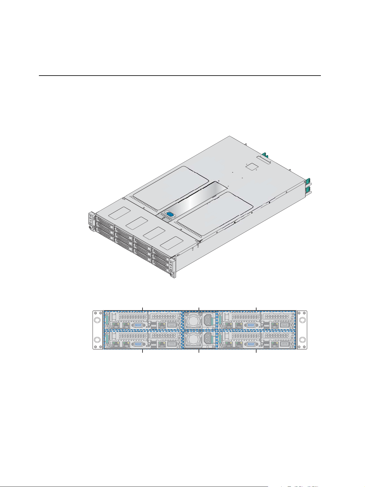
Compute Module 4
Compute Module 2 Power Supply 1
Power Supply 2
Compute Module 3
Compute Module 1
This chapter briefly describes the main features. This includes illustrations of
the product, a list of the product features, and diagrams showing the location
of important components and connections.
1
Figure 1. Product Overview
Figure 2. Product Rear View
Page 4
Product Feature Overview
The following table summarizes the features of the product.
Table 1. Product Feature Set
Feature Description
Dimensions H2312XXKR2
• 3.42 inches (86.9 mm) high
• 17.24 inches (438 mm) wide
• 30.35 inches (771 mm) deep
H2216XXKR2
• 3.42 inches (86.9 mm) high
• 17.24 inches (438 mm) wide
• 28.86 inches (733 mm) deep
Package Dimensions 984X578X266 mm
Weight H2312XXKR2 Net weight 21.5kg, package weight 29.5k
2 Net weight 20.5kg, package weight 28.4kg
• Intel® Compute Module HNS2600KP Product Family
mpute Module Support
Co
H2216XXKR
g
• Intel® Compute Module HNS2600TP Product Family
System Fans
• One internal power supply fan for each installed power supply unit
• Three fans for each compute module
Power Supply Options 1600W AC Common Redundant Power Supply (CRP
with PFC, supporting CRPS configuration
Storage Bay Options
• 12x 3.5-inch SATA/SAS drive bays – H2312XXKR2
• 16x 2.5-inch SATA/SAS drive bays – H2216XXKR2
S), 80 plus Platinum
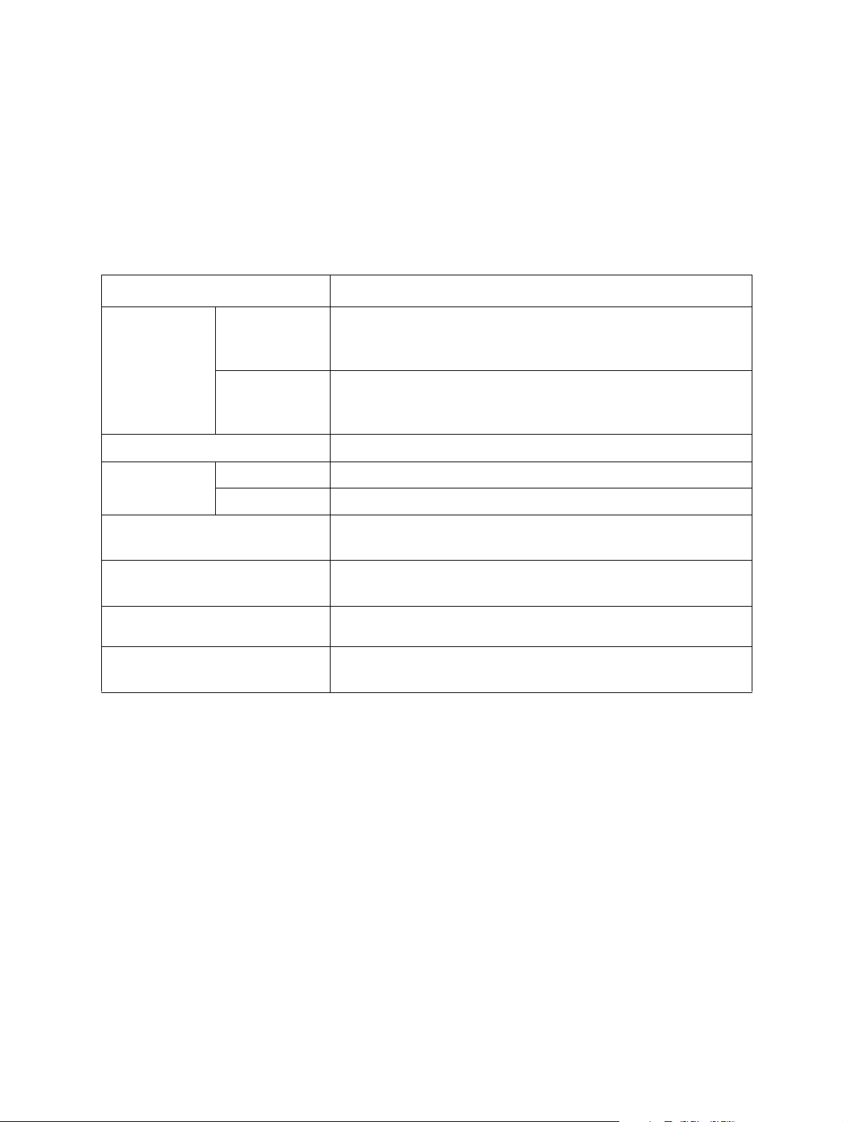
Server Chassis Components
This section helps you identify the components of your product. If you are near
the server chassis, you can also use the Quick Reference Label provided on the
chassis cover to assist in identifying the components.
The Server Chassis supports four compute modules in the chassis. The whole
chassis view is as below (with the power distribution module cover removed).
2
Page 5
B
C
D
LOCK
UNLOCK
Note: The
removed, keep the dummy tray cover properly for future use.
Note: Th
installed and powered up or a dummy tray cover installed to maintain proper
thermal environment for the other running compute modules in the same
chassis. In case of a compute module failure, remove the failed compute module,
and replace with a dummy tray cover until the new compute module is installed.
A
Label Description
A Front control panels
B Drive bays
C Power distribution module
D Power supply modules
E Hot-swap backplane (attached to the drive cage)
E
AF006407
Figure 3. Server Chassis Components
blank compute module bay must be covered by a dummy tray cover. When
e compute module bay in the chassis requires either a compute module being
3
Page 6
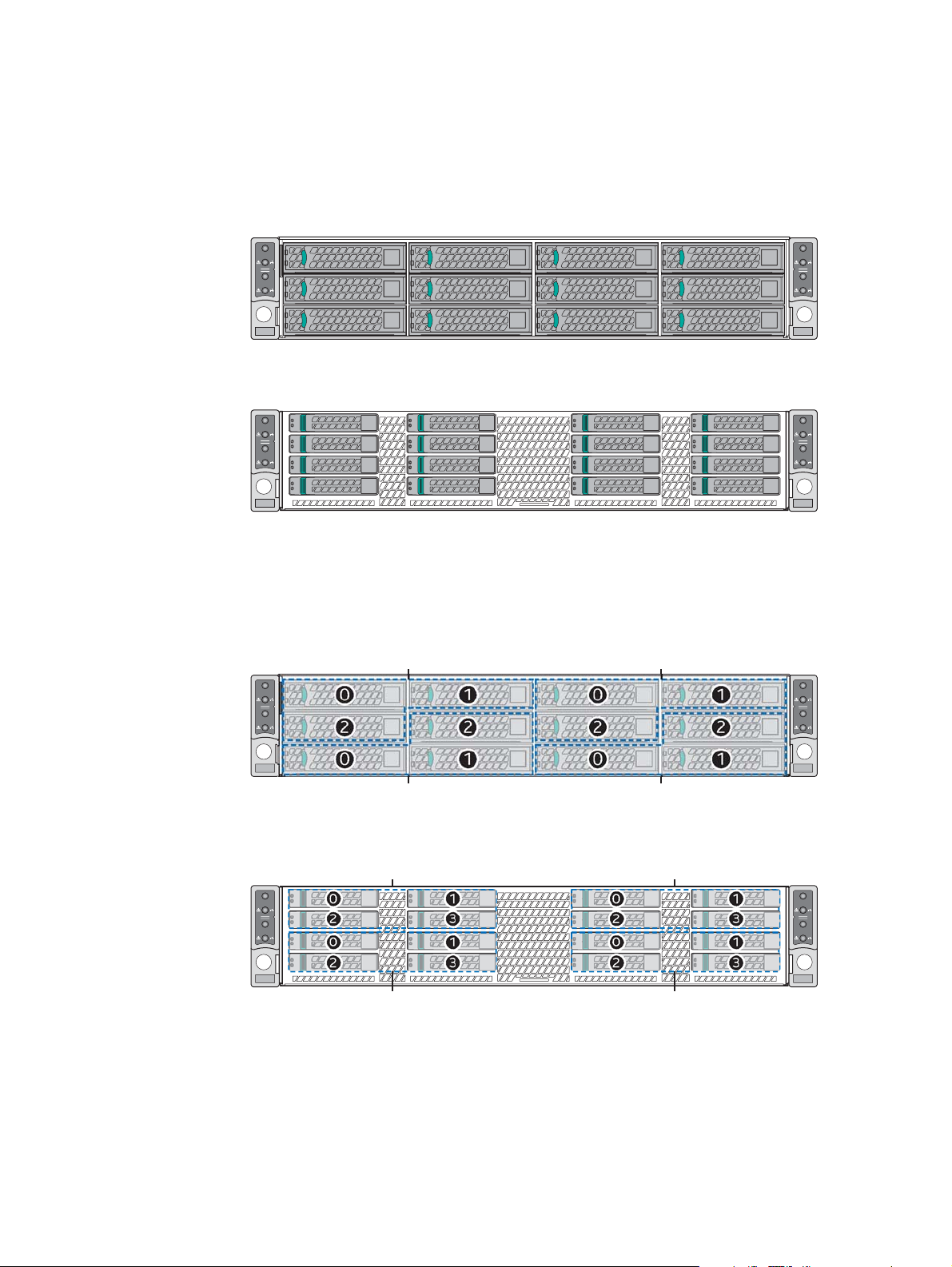
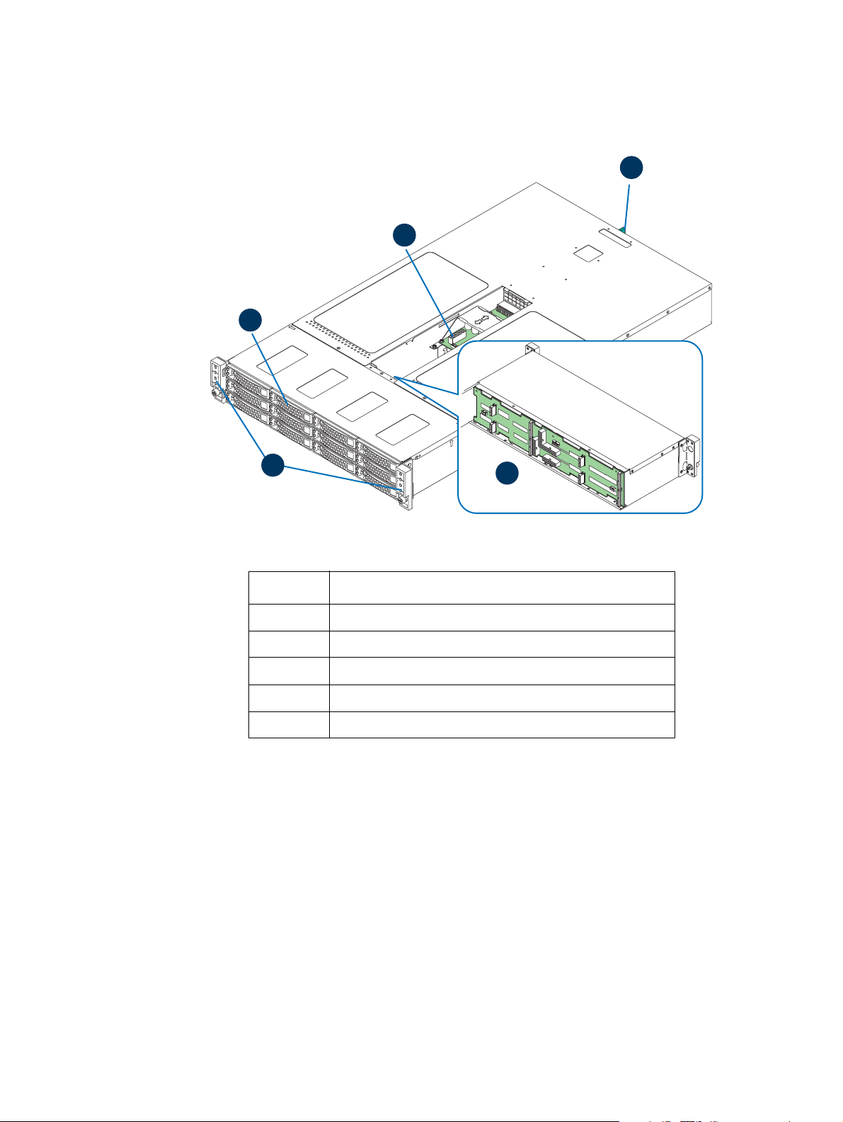
Drive Bay
AF006720
NODE 4
NODE 2
NODE 3
NODE 1
AF006721
NODE 4
NODE 2
NODE 3
NODE 1
AF006515
NODE 4
NODE 2
NODE 3
NODE 1
0
0
2 2
1
1
Compute Module 3
Compute Module 1
0
0
2 2
1
1
Compute Module 4
Compute Module 2
AF006516
NODE 4
NODE 2
NODE 3
NODE 1
0 1
2
3
0 1
2 3
0 1
2
3
0 1
2 3
Compute Module 1 Compute Module 2
Compute Module 3 Compute Module 4
Each compute module has a dedicated drive array based on the backplane
c
ontroller design. Following are schemes for the drive array corresponding to
the compute module.
Figure 4. Front View
Figure 5. Front View
Figure 6. Drive Array Scheme
Figure 7. Drive Array Scheme on the
4
Page 7
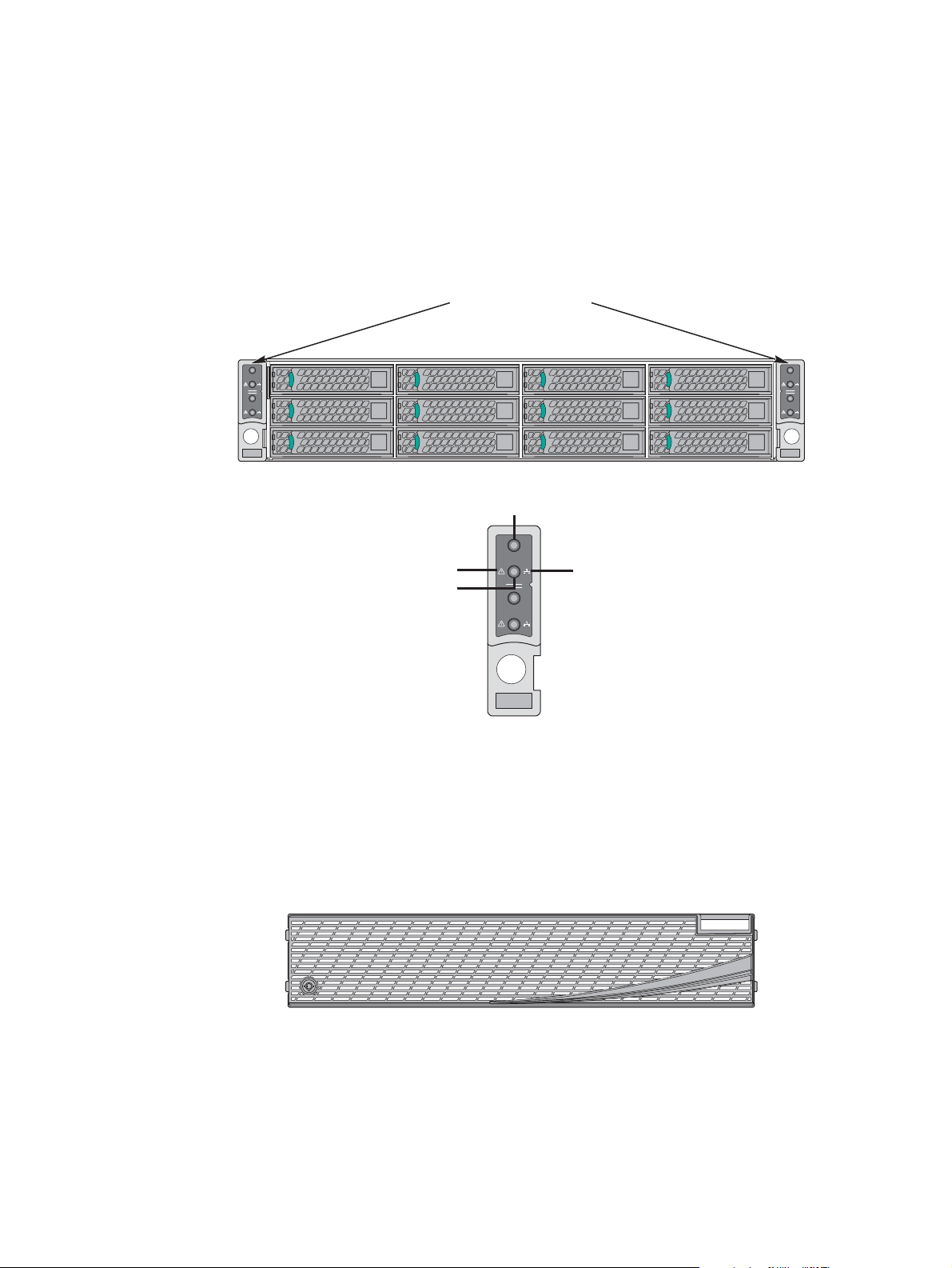
Front Control Panel
NODE 3
NODE 1
Power Button with LED
ID Button
with LED
Status LED
Network
Link/Activity
LED
AF006671
The server chassis contains two sets of control panels on the left and right rack
handles. Each control panel contains two sets of control buttons and LEDs for
each compute module. Following is the scheme of the control panel.
Front Controls and LEDs
NODE 3
NODE 1
Front Bezel
Figure 8. Front Cont
NODE 4
NODE 2
AF006722
rol Panel Options
The front bezel is available as an optional accessory for the server chassis.
AF004476
Figure 9. Front Bezel
5
Page 8
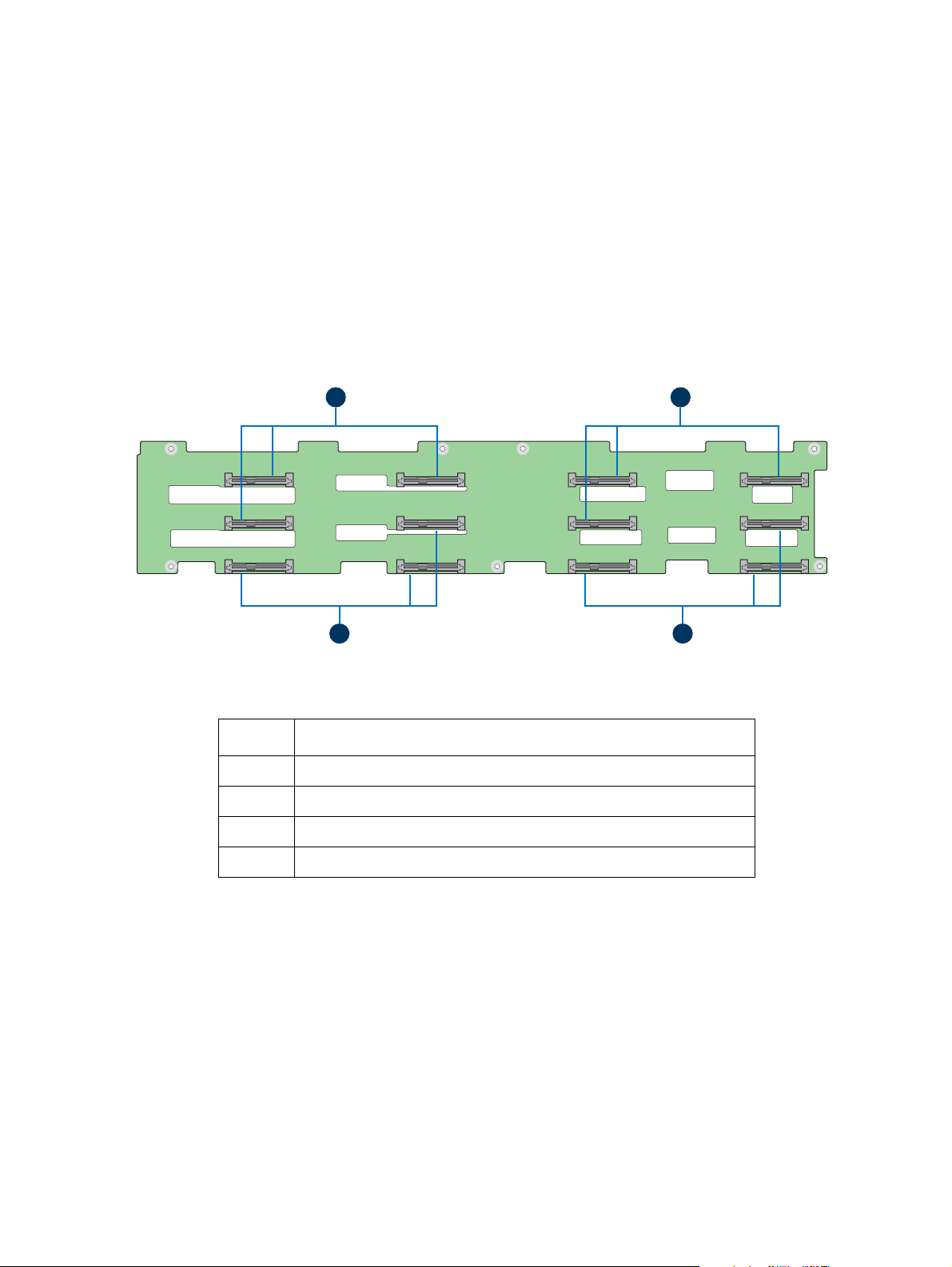
Hot-Swap SAS/SATA Backplane
AF006418
C
A B
D
The hot-swap SAS/SATA backplane serves as an interface between the mother
board and the drives. The following diagrams show the location for each
connector found on the backplane.
3.5" Hot-swap Backplane
Label Description
A SATA/SAS connectors for node 1
B SATA/SAS connectors for node 2
C SATA/SAS connectors for node 3
D SATA/SAS connectors for node 4
Figure 10. 3.5" Backplane Components (Front View)
6
Page 9
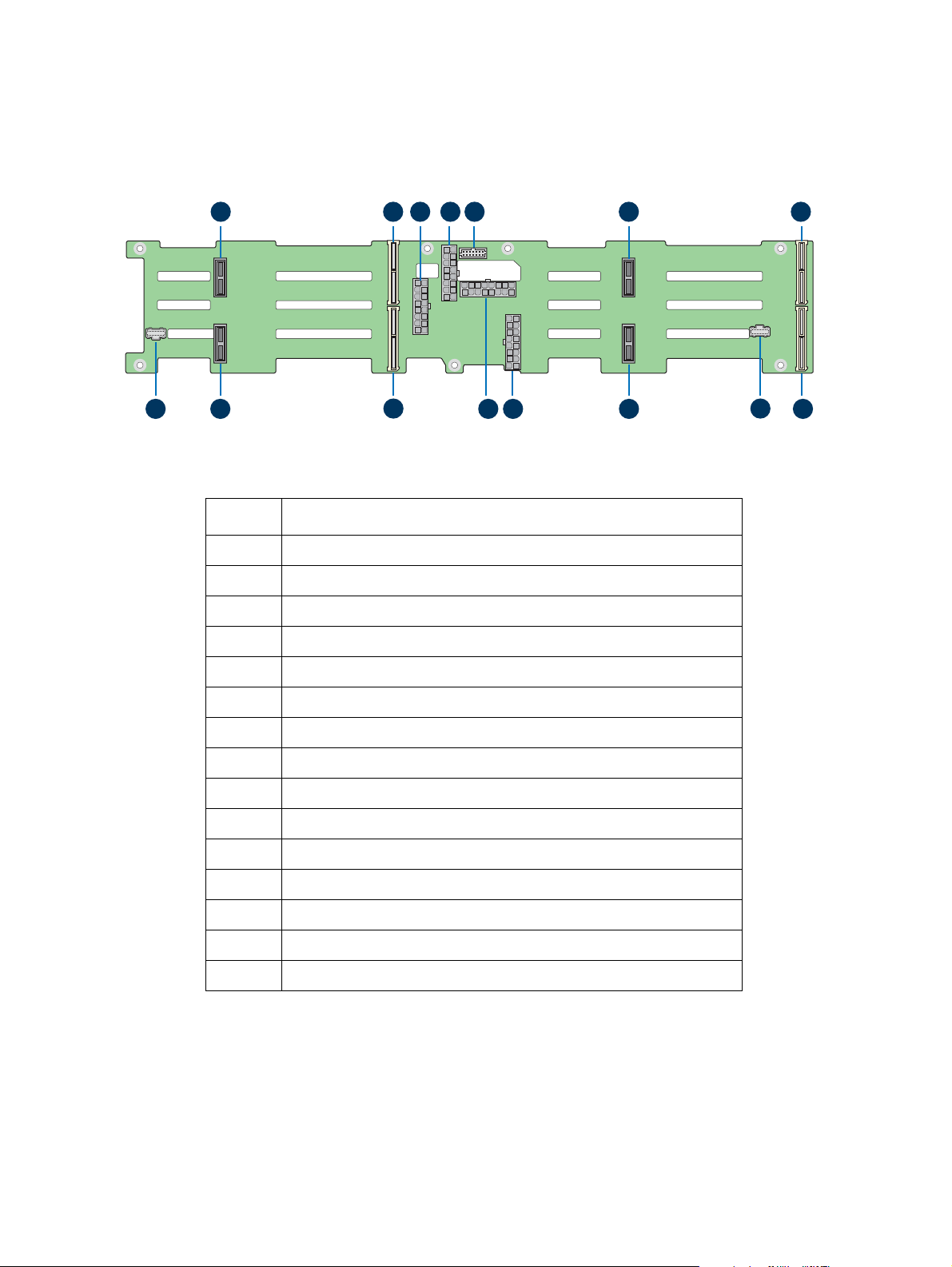
AF006419
A B C D E F G
HIJL
O
N
M
K
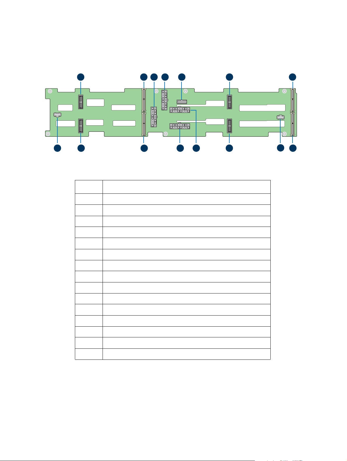
Label Description
A 2-blade compute module power connector for node 4
B 2x40 pin bridge board connector for node 4
C 2x9 pin power supply input connector
D 2x9 pin Power supply input connector
E 2x7 pin power control cable connector
F 2-blade compute module power connector for node 3
G 2x40 pin bridge board connector for node 3
H 2x40 pin bridge board connector for node 1
I 20-pin front panel cable connector for node 1 and 3
J 2-blade compute module power connector for node 1
K 2x9 pin power supply input connector
L 2x9 pin power supply input connector
M 2x40 pin bridge board connector for node 2
N 2-blade compute module power connector for node 2
O 20-pin front panel cable connector for node 2 and 4
Figure 11. 3.5" Backplane Components (Back View)
7
Page 10
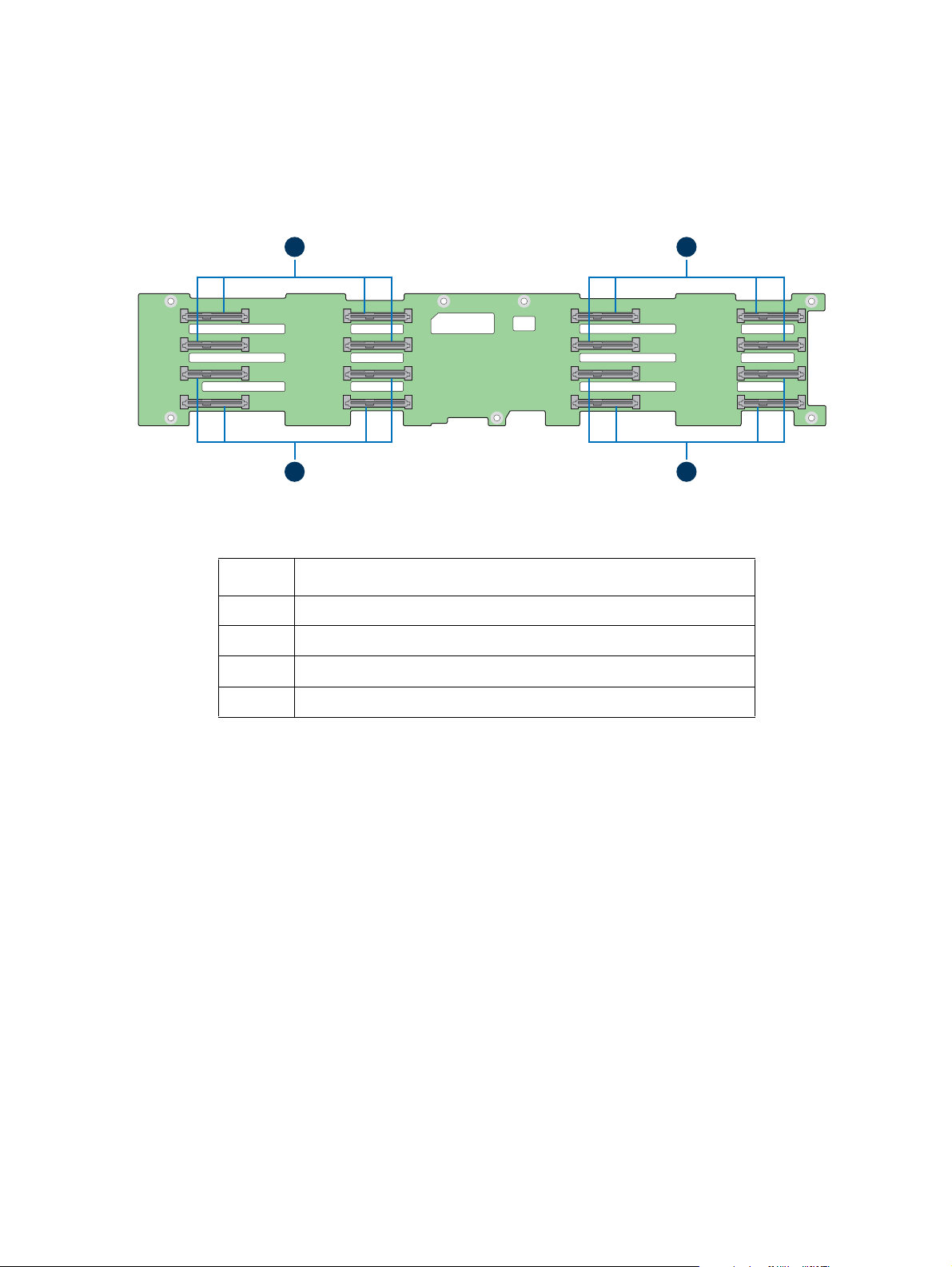
2.5" Hot-swap Backplane
C
AF006410
D
A B
Label Description
A SATA/SAS connectors for node 1
B SATA/SAS connectors for node 2
C SATA/SAS connectors for node 3
D SATA/SAS connectors for node 4
Figure 12. 2.5" Backplane Components (Front View)
8
Page 11
AF006411
A B C D F G
H
I
JKLNO
M
E
Label Description
A 2-blade compute module power connector for node 4
B 2x40 pin bridge board connector for node 4
C 2x9 pin power supply input connector
D 2x7 pin power control cable connector
E 2x9 pin power supply input connector
F 2-blade compute module power connector for node 3
G 2x40 pin bridge board connector for node 3
H 2x40 pin bridge board connector for node 1
I 20-pin front panel cable connector for node 1 and 3
J 2-blade compute module power connector for node 1
K 2x9 pin power supply input connector
L 2x9 pin power supply input connector
M 2x40 pin bridge board connector for node 2
N 2-blade compute module power connector for node 2
O 20-pin front panel cable connector for node 2 and 4
Figure 13. 2.5" Backplane Components (Back View)
9
Page 12

Dummy Tray Cover
AF006723
The dummy tray cover is shipped together with the chassis. It must be removed
before installing the compute module, or it must be restored if the compute
module is not to be installed.
Figure 14. Dummy Tray Cover
10
Page 13

2 Hardware Installations and
Upgrades
Before You Begin
Before working with your server product, pay close attention to the Safety
Information at the beginning of this manual.
Warning: The transparent
removed for proper system cooling.
Note: Whe
never you service the server chassis, you must first power down the server
and unplug all peripheral devices and the AC power cord.
plastic protective films on the chassis top surface must be
Tools and Supplies Needed
• Phillips* (cross head) screwdriver (#1 bit and #2 bit)
• Needle nosed pliers
• Anti-static wrist strap and conductive foam pad (recommended)
System Reference
All references to left, right, front, top, and bottom assume that the reader is
facing the front of the chassis as it would be positioned for normal operation.
11
Page 14

Removing and Installing the Front Bezel
AF005160
Badge
A
B
The server chassis supports the installation of an optional front bezel (Intel
product code: A2UBEZEL). The bezel kit includes a plastic lockable front bezel
and multiple bezel snap-ons allowing for OEM differentiation.
Bezel Snap-ons
The bezel kit provides three different bezel snap-ons to allow for OEM
differentiation; two different size badging snap-ons, and one decorative wave
snap-on.
To mount the snap-on to the bezel, insert the snap-on hooks into the bezel and
press to snap it into place.
Badge
AF005159
Figure 15. Installing the Snap-on to the Front Bezel
To remove the snap-on from the bezel, squeeze the hooks at the rear of the
snap-on to
release it (see letter A). Then remove the snap-on from the bezel (see
letter B).
Figure 16. Removing the Snap-on from the Front Bezel
12
Page 15

Removing the Front Bezel
AF006421
A
B
AF006422
B
A
If your server chassis includes a front bezel, follow these steps to remove it from
the chassis:
1. Unlock the bezel.
2. Pull out the left side of the bezel
3. Rotate the left side of the bezel out away
latches
on the right side from the rack handle (see letter B).
Figure 17. Removing the Front Bezel
Installing the Front Bezel
Note: Before installing the front bezel, you must install the rack handles.
1. Lock the right side of the bezel to the rack handle (see letter A).
from the rack handle (see letter A).
from the chassis to release the
2. Rotate the left side of the bezel towards the chassis and press
of the
bezel into the rack handle until it clicks into place (see letter B).
the left side
3. Lock the bezel.
Figure 18. Installing the Front Bezel
13
Page 16

Removing and Installing the Power Distribution
Module Cover
Removing the Power Distribution Module Cover
The server chassis must be operated with the power distribution module cover
in place to ensure proper cooling. You will need to remove the cover to add or
replace the components inside of the chassis. Before removing the cover, power
down the server and unplug all peripheral devices and the power cables.
Note: A n
the server chassis from sliding on your work surface.
on-skid surface or a stop behind the server chassis may be needed to prevent
1. Remove the screw (see letter A).
2. Lift the cover from the front end to more than 45 degrees (see letter B
and
remove the cover.
)
A
LOCK
UNLOCK
B
AF006423
Figure 19. Removing the Power Distribution Module Cover
14
Page 17

Installing the Power Distribution Module Cover
AF006424
LOCK
UNLOCK
B
A
1. Place the cover onto the chassis and slide forward until the front edge of
the cover is pressed up against the back edge of the front drive bay (see
lett
er A).
2. Rotate the front end of the cover down to position and fix the cover
the sc
rew (see letter B).
Figure 20. Installing the Power Distribution Module Cover
with
15
Page 18

Removing and Installing the Compute Module
AF006703
Latch
AF006426
Latch
Each compute module is identical in the chassis. They are designed for either
“cold” or “hot” swappable. The compute module can only be plugged from the
rear chassis.
Installing the Compute Module
1. While pressing the latch, pull out the dummy tray cover.
Figure 21. Removing the Dummy Tray Cover
2. Align and slide the compute module into the chassis.
Note: Wh
en the upper compute module is being inserted into the chassis,
make sure its front edge overrides the air duct edge of the lower
compute module.
3. While pressing the latch, push the compute module along the chassis rail
until the latch locks in
position.
Figure 22. Installing the Compute Module
16
Page 19

Removing the Compute Module
AF006425
Latch
Handle
1. While pressing the latch, pull out the handle with the compute module.
Figure 23. Removing the Compute Module
2. Restore the dummy tray cover.
AF006704
Figure 24. Restoring the Dummy Tray Cover
17
Page 20

Removing and Installing the Redundant Power
Handle
Latch
AF006675
Handle
Latch
AF006674
Supply Unit
The server chassis is equipped with two redundant power supply units. Each of
them can be hot-swappable.
Caution: Installing
chassis is not supported. Doing so will not provide power supply redundancy and
will result in multiple errors being logged.
two power supply units with different wattage ratings in a server
Removing the Power Supply Unit
While pressing the latch, pull out the handle with the power supply unit.
Figure 25. Removing the Power Supply Unit
Installing the Power Supply Unit
1. Align and slide the power supply unit into the power cage.
2. While pressing the latch, push the power supply unit
rail until the lat
ch locks in position.
Figure 26. Installing the Power Supply Unit
along the power cage
18
Page 21

Installing a Hot-swap Storage Device
TOP
A
B
AF006699
Note: To maintain proper system cooling, all externally accessable drive bays must be
populated with a carrier mounted with a storage device (hard disk drive (HDD) or
Solid State Device (SSD)) or with a supplied drive blank.
3.5” Hard Disk Drive Assembly
1. Remove the drive carrier from the chassis by pressing the green button
and
pulling open the lever (see letter A).
2. Pull the carrier out of the drive bay (see letter B).
Figure 27. 3.5” HDD Assembly – Removing the Carrier
3. Remove the four screws securing the
plastic drive blank to the carrier.
4. Remove the drive blank from the carrier (see letter C).
BREAK OFF TAB
BEFORE MOUTING
2.5´´ HARD DRIVE
TOP
C
AF004072
Figure 28. 3.5” HDD Assembly – Removing the Drive Blank
19
Page 22

5. Install the hard disk drive into the carrier. Verify the connector end of the
F
E
AF006700
drive is located towards the back of the carrier (see letter D).
6. Secure the drive to the carrier using the four screws.
3.5´´ HDD
D
AF004073
Figure 29. 3.5” HDD Assembly – Installing the Hard Disk Drive
7. With the lever open, insert the carrier assembly
into the chassis (see
letter E). Push in the lever to lock it into place (see letter F).
Figure 30. 3.5” HDD Assembly – Inserting the Carrier Assembly
20
Page 23

Option to Install a 2.5” Solid State Device into a 3.5” Carrier
AF006499
d1
AF006502
TOP
INSTALL
THIS SIDE UP
d2
AF006500
SSD
d3
d4
AF006501
SSD
Note: To maintain system thermals, all drive bays must be populated with a drive tray
mounted with a hard disk drive, SSD, or supplied drive blank.
The provided 3.5” drive blank can also be used as a 2.5” device bracket, allowing
5” SSD to be installed into a 3.5” device carrier.
a 2.
1. Remove the device carrier from the drive bay. See 3.5” Hard Disk
Drive
Assembly.
2. Remove the drive blank from the device carrier. See
3.5” Hard Disk Drive
Assembly.
3. Break off the small side tab from the drive blank, making the drive blan
into a
4. Install the device bracket into the device
the
device bracket (see letter d1).
carrier so that the hollow side of
device bracket is facing down.
5. Secure the device bracket with the three screws (see letter d2).
6. Turn the carrier assembly over.
7. Slide a 2.5" SSD into the device bracket and ali
right
and left rail (see letter d3).
8. Secure the device using the fou
r screws (see letter d4).
9. Insert the carrier assembly into the chassis. See 3.5”
gn the screw holes with the
Hard Disk Drive
Assembly.
k
21
Figure 31. Option to Install the 2.5” SSD into a 3.5” Drive Blank
Page 24

Note: Due to degraded performance and reliability concerns, the use of the 3.5” drive
AF006701
AF004040
D
C
blank as a 2.5” device bracket is intended to support SSD type storage devices
only. Installing a 2.5” hard disk drive into the 3.5” drive blank cannot be
supported.
2.5” Storage Device (HDD or SSD) Assembly
1. Remove the drive carrier from the chassis by pressing the green button
an
d pulling open the lever (see letter A).
2. Pull the carrier out of the drive bay (see letter B).
B
A
Figure 32. 2.5” HDD or SSD Assembly – Removing the Carrier
3. Remove the four screws securing the plastic dri
ve blank to the carrier (see
letter C).
4. Remove the drive blank from the carrier (see letter D).
Figure 33. 2.5” HDD or SSD Assembly – Removing the Drive Blank
22
Page 25

5. Install the storage device into the carrier. Verify the connector end of the
2.5" HDD
AF006702
G
F
st
orage device is located towards the back of the carrier (see letter E).
6. Secure the storage device to the carrier using the four screws.
E
AF004041
Figure 34. 2.5” HDD or SSD Assembly
7. With the lever open, insert the carrier assembly into the ch
lett
er F). Push in
the lever to lock it into place (see letter G).
– Installing the 2.5” HDD or SSD
assis (see
Figure 35. 2.5” HDD or SSD Assembly – Inserting the Carrier Assembly
23
Page 26

Replacing the 2.5" Backplane Board
A
B
C
AF006465
Removing the 2.5" Backplane Board
1. Remove all hot-swap drive carriers, regardless of whether a drive is
in
stalled in the carrier.
2. Remove the power distribution module cover. For instructions,
Removing the Power Distribution Module Cover.
3. Disconnect all cables from the backplane board.
4. Remove the drive cage screws (see letters A and B) and pull out
c
age (see letter C).
see
the drive
Figure 36. Removing the Drive Cage
24
Page 27

5. Remove the screws from the backplane board (see letter D) and de-attach
AF006469
D
E
the
backplane board from the drive cage (see letter E).
Figure 37. Removing the 2.5" Backplane Board from the Drive Cage
Installing the 2.5" Backplane Board
1. Attach the backplane board to the drive cage (see letter A) and fix the
backplane board with
the screws (see letter B).
A
B
AF006470
Figure 38. Installing the 2.5" Backplane Board to the
Drive Cage
25
Page 28

2. Install the drive cage to the chassis (see letter C) and fix the drive cage with
E
D
C
AF006468
the screws (see letters D and E).
Figure 39. Installing the Drive Cage to the Chassis
3. Reconnect all cables to the backplane board.
4. Install the power distribution module cover. For instructions, see Installing
the Power Distribution Module Cover.
5. Install all hot-swap drive carriers if removed.
26
Page 29

Replacing the 3.5" Backplane Board
A
B
C
AF006465
Removing the 3.5" Backplane Board
1. Remove all hot-swap drive carriers, regardless of whether a drive is
installe
d in the carrier.
2. Remove the power distribution module co
Removing the Power Distribution Module Cover.
3. Disconnect all cables from the backplane board.
4. Remove the drive cage screws (see letters A and B)
cage (see letter C).
ver. For instructions, see
and pull out the drive
Figure 40. Removing the Drive Cage
27
Page 30

5. Remove the screws from the backplane board (see letter D) and de-attach
AF006466
D
E
AF006467
B
A
t
he backplane board from the drive cage (see letter E).
Figure 41. Removing the 3.5" Backplane Board from the Drive Cage
Installing the 3.5" Backplane Board
1. Attach the backplane board to the drive cage (see letter A) and fix the
backplane board with the screws (see letter B).
Figure 42. Installing the 3.5" Backplane Board to the Drive Cage
28
Page 31

2. Install the drive cage to the chassis (see letter C) and fix the drive cage with
E
D
C
AF006468
the
screws (see letters D and E).
Figure 43. Installing the Drive Cage to the Chassis
3. Reconnect all cables to the backplane board.
4. Install the power distribution module cover. For instructions, see Installi
the Power Distribution Module Cover.
5. Install all hot-swap drive carrier
s if removed.
ng
29
Page 32

Removing and Installing the Power Distribution
AF006471
LOCK
UNLOCK
A
B
AF006472
LOCK
UNLOCK
A
B
Module
Removing the Power Distribution Module
1. Remove the cover and the power supply units from the chassis.
2. Remove the power cables and the PMBus* cable between the powe
d
istribution module and the backplane.
3. Remove the two screws (see letter A)
module and lift
it (see letter B).
and slide the power distribution
Figure 44. Removing the Power Distribution Module
Installing the Power Distribution Module
1. Slide in the power distribution module (see letter A) and fix the module
with
the two screws (see letter B).
r
Figure 45. Installing the Power Distribution Module
2. Connect the power cables and the PMBus* cable to the
power distribution
module.
3. Close the cover and install the power supply units.
30
Page 33

Replacing the Front Control Panel Board
AF004709AAF004711
B
Removing the Front Control Panel Board
1. Remove the four screws on the back of the rack handle (see letter A). Be
careful of the front panel cable on the back.
Figure 46. Removing the Front Control Pan
2. Disconnect the cable from the front control panel board (see letter B).
Figure 47. Disconnecting the Front Panel Cable
el Assembly from the Rack Handle
31
Page 34

3. Remove the two screws from the back of the front control panel board
AF004707
A
(see lette
r C) and remove the bo
ard.
C
AF004712
Figure 48. Removing the Front Control Panel
Installing the Front Control Panel Board
1. Install the front control panel board to the panel shell with the two screws
(see lette
r A).
Figure 49. Installing the Front Control Panel Board
Board
32
Page 35

2. Connect the cable to the front control panel board (see letter B).
AF004708
B
Figure 50. Connecting the Front Panel Cable
3. Install the front control panel assembly to the rack handle with the
screws (see
letter C).
C
AF004710
Figure 51. Installing the Front Control
Panel Assembly to the Rack Handle
four
33
 Loading...