

Page 1
Thank you for buying an Intel® Server System. The following information will help you
assemble your Intel® Server System and install components.
If you are not familiar with ESD [Electrostatic Discharge] procedures used during
system integration, see the complete ESD procedures described in your Service Guide.
This guide and other supporting documents are located on the web at:
http://www.intel.com/support.
G54451-002
Intel® Server System H2000JF & H2000WP
Quick Installation User's Guide
Intel® Server System H2000JF & H2000WP
Quick Installation User's Guide
*
12 x 3.5" hard drive bay system as shown
Page 2

( This page is intentionally left blank. )
Page 3

i
Table of Contents
Reference .......................................................................................................................................... 12
Intel® Server Board S2600JF Component Layout............................................ 12
Intel® Server Board S2600WP Component Layout ........................................ 12
Front Panel Controls and Indicators........................................................................ 13
Cable Routing inside Server System H2000JF Node Tray
...................................... 13
Optional Accessories
............................................................................................................ 13
Cable Routing inside Server System H2000WP Node Tray
.................................. 14
Optional Accessories
............................................................................................................ 14
Intel® Server System RAID Options ........................................................................ 14
Intel® Server System RAID Options ........................................................................ 15
System Overview (Intel® Server System H2000JF Family)..........................................1
System Overview (Intel® Server System H2000WP Family) ......................................2
General Installation Process ..........................................................................................................3
Preparing the System ...................................................................................................... 3
Install/Remove the Power Supply Unit .................................................................. 3
Install/Remove Computer Node Tray ...................................................................... 3
Install/Remove Node Tray Air Duct .......................................................................... 4
Remove Processor Heat Sink(s) .................................................................................. 4
Install the Processor(s) .................................................................................................... 5
Install Processor Heat Sink(s) ...................................................................................... 6
Install Memory Modules .................................................................................................. 6
Install/Remove the Front Bezel .................................................................................. 7
Install Hard Drives .............................................................................................................. 7
Installing PCI Riser Assembly and Add-in Card on Riser Slot 1.................. 8
Install I/O Module Riser and Carrier Assembly on Riser Slot 2 .................. 9
Install Intel® RAID C600 Upgrade Key (optional)................................................ 9
Install Intel® Remote Management Module 4 (optional) ................................ 9
Remove the Top Cover ..................................................................................................10
Install Top Cover ................................................................................................................ 10
Software ................................................................................................................................10
Assembling the Server System with Server Chassis H2000 .................. 11
Removing a Node Tray from a Chassis.................................................................. 11
Page 4
ii
Warning
Read all caution and safety
statements in this document
before performing any of the
instructions. Also see the Intel®
Server Board and Server Chassis
Safety Information document at:
http://www.intel.com/support/
motherboards/server/sb/cs-010770
.htm for complete safety information.
Warning
Installation and service
of this product to be
performed only by
qualified service personnel
to avoid risk of injury from
electrical shock or energy
hazard.
Caution
Observe normal ESD
[Electrostatic Discharge]
procedures during system
integration to avoid possible
damage to server board and/or
other components.
Tools Required
Anti-static
wrist strap
Phillips*
screwdriver
Flat Blade
screwdriver
Intel is a registered trademark of Intel Corporation or its subsidiaries in the United States and other countries. *Other names and brands may be claimed as the
property of others. Copyright © 2012, Intel Corporation. All rights reserved.
Thermal Operation and Configuration Requirements for Server System H2000WP
To keep the system operating within supported maximum thermal limits, the system must meet the following operating and
configuration guidelines:
• Ambient in-let temperature cannot exceed 35º C and should not remain at this maximum level for long periods of time.
Doing so may affect long term reliability of the system.
• The CPU-1 processor + CPU heatsink must be installed first. The CPU-2 heatsink must be installed at all times, with or
without a processor installed.
• Memory Slot population requirements:
NOTE: Specified memory slots either can be populated with a DIMM or supplied DIMM Blank. Memory population rules
apply when installing DIMMs.
▪ DIMM Population Rules on CPU-1
Install DIMMs in order: channels A1, B1, C1, D1, A2, B2, C2, and D2. Remove only DIMM blanks when populating
▪ DIMM Population on CPU-2
Install DIMMs in order: Channels E1, F1, G1, H1, E2, F2, G2, and H2. Only remove DIMM blanks when populating
• All hard drive bays must be populated. Hard drive carriers either can be populated with a hard drive or supplied
drive blank.
• The air duct must be installed at all times.
• The empty power supply bay must have the supplied filler blank installed at all times.
• The system top-cover must be installed at all times. Remove the top cover only when the system is in power-off state.
the slot with a DIMM.
the slot with a DIMM.
Page 5

iii
Warning
Read all caution and safety
statements in this document
before performing any of the
instructions. Also see the Intel®
Server Board and Server Chassis
Safety Information document at:
http://www.intel.com/support/
motherboards/server/sb/cs-010770
.htm for complete safety information.
Warning
Installation and service
of this product to be
performed only by
qualified service personnel
to avoid risk of injury from
electrical shock or energy
hazard.
Caution
Observe normal ESD
[Electrostatic Discharge]
procedures during system
integration to avoid possible
damage to server board and/or
other components.
Tools Required
Anti-static
wrist strap
Phillips*
screwdriver
Flat Blade
screwdriver
Intel is a registered trademark of Intel Corporation or its subsidiaries in the United States and other countries. *Other names and brands may be claimed as the
property of others. Copyright © 2012, Intel Corporation. All rights reserved.
Thermal Operation and Configuration Requirements for Server System H2000JF
To keep the system operating within supported maximum thermal limits, the system must meet the following operating and
configuration guidelines:
• Ambient in-let temperature cannot exceed 35º C and should not remain at this maximum level for long periods of time.
Doing so may affect long term reliability of the system.
• The CPU-1 processor + CPU heatsink must be installed first. The CPU-2 heatsink must be installed at all times, with or
without a processor installed.
• Memory Slot population requirements:
NOTE: Specified memory slots either can be populated with a DIMM or supplied DIMM Blank. Memory population rules
apply when installing DIMMs.
▪ DIMM Population Rules on CPU-1
Install DIMMs in order; Channels A, B, C, and D. Only remove DIMM blanks when populating the slot with a DIMM.
▪ DIMM Population on CPU-2
Install DIMMs in order; Channels E, F, G, and H. Only remove DIMM blanks when populating the slot with a DIMM.
• All hard drive bays must be populated. Hard drive carriers either can be populated with a hard drive or supplied
drive blank.
• The air duct must be installed at all times.
• The empty power supply bay must have the supplied filler blank installed at all times.
• The system top-cover must be installed at all times. Remove the top cover only when the system is in power-off state.
Page 6

1
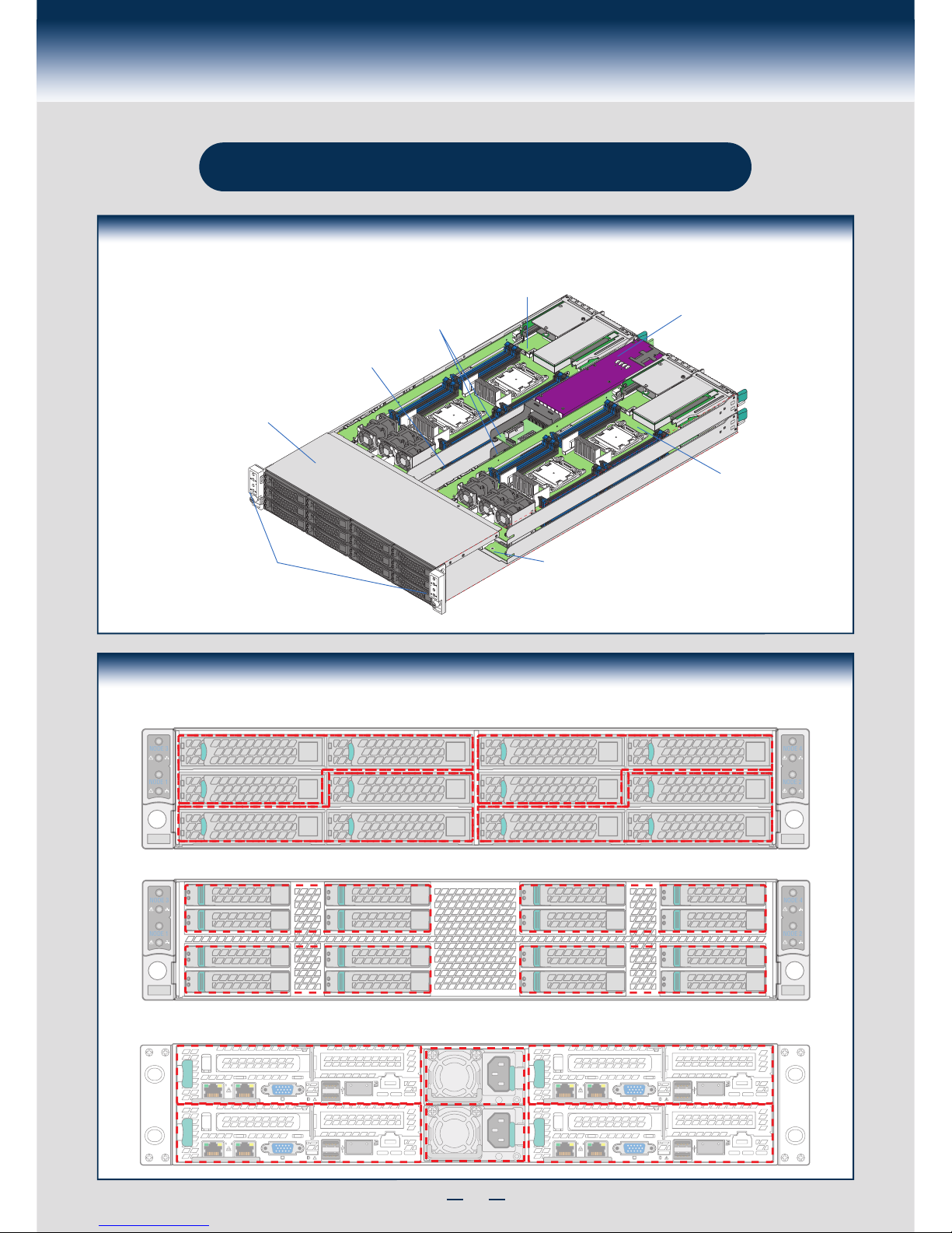
System Overview
Intel® Server System H2000JF Family
System Features and Components
* 3.5" Hard Drive Bay system as shown
OPEN 1st
CLOSE 1st
OPEN 1st
CLOSE 1st
OPEN 1st
CLOSE 1st
OPEN 1st
CLOSE 1st
OPEN 1st
CLOSE 1st
OPEN 1st
CLOSE 1st
OPEN 1st
CLOSE 1st
OPEN 1st
CLOSE 1st
Compute
Node 3 Tray
Upper/Lower
Power Distribution
Boards
Common
Redundant
Power Supply
Compute
Node 1 Tray
Front Control Panel
HDD bays with
Hot Swap
Backplane
Compute
Node 4 Tray
Compute
Node 2 Tray
Page 7
2
System Overview
Intel® Server System H2000WP Family
* 3.5" Hard Drive Bay system as shown
System Features and Components
Compute
Node 3 Tray
Upper/Lower
Power Distribution
Boards
Common
Redundant
Power Supply
Compute
Node 1 Tray
Front Control Panel
HDD bays with
Hot Swap
Backplane
Compute
Node 4 Tray
Compute
Node 2 Tray
Intel® Server System H2000JF and H2000WP Hard Drive Numbering Diagram
Intel® Server System H2000JF and H2000WP Compute Node Numbering Diagram - Rear View
Node 4
Node 2
Node 3
Node 1
PSU 2
PSU 1
12X3.5” Hard Drive Bay Option - Front View
NODE 4
NODE 2
NODE 3
NODE 1
Node3/HDD0
Node3/HDD2
Node1/HDD0
Node3/HDD1
Node1/HDD2
Node1/HDD1
Node4/HDD0
Node4/HDD2
Node2/HDD0
Node4/HDD1
Node2/HDD2
Node2/HDD1
Node3/HDD1
Node1/HDD2
Node1/HDD1
16X2.5” Hard Drive Bay Option - Front View
NODE 4
NODE 2
NODE 3
NODE 1
Node1/HDD2
Node1/HDD0
Node3/HDD2
Node3/HDD0
Node1/HDD3
Node1/HDD1
Node3/HDD3
Node3/HDD1
Node2/HDD2
Node2/HDD0
Node4/HDD2
Node4/HDD0
Node2/HDD3
Node2/HDD1
Node4/HDD3
Node4/HDD1
Page 8

3
General Installation Process
The installation instructions in this section are for common components of Intel® Server System
H2000JP and H2000WP family.
Minimum Hardware Requirements
• Memory Type:
Minimum of one 1GB DDR3 1066/1333/1600 MHz RDIMM.
• Processor:
Intel® Xeon® processor E5-2600 product family (TDP 130W or below).
• Hard Disk Drives: SATA/SAS
For a complete list of compatible processors, heatsinks, and memory, see
http://www.intel.com/p/en_US/support (post-production only)
To avoid integration difficulties and possible board damage, your system must
meet the following minimum requirements:
1
Preparing the System
Observe normal ESD (Electrostatic Discharge)
procedures.
Place your Intel® Server System on a flat anti-static
surface to perform the following integration procedures.
Observe ESD procedures before reaching inside to make
server board connections or install components.
2
Install/Remove the Power Supply Unit
A
Align and slide in the Power Supply Unit to the power cage rail.
B
A
B
Carefully push in the latch on the right hand of PSU.
Pull the handle with the PSU while still press the latch.
Push the Power Supply Unit along the rail until the latch locks in
position with a “tick” sound.
Install the Power Supply Unit: Remove the Power Supply Unit:
3
Remove/Install Computer Node Tray
Push-in the latch on the left hand of Node Tray.
To Remove Node Tray: To Install Node Tray:
A
B
Pull the handle of the Node Tray while pushing the latch.
Align and slide in the Node Tray to the chassis rail.
A
B
Push the Node Tray along the rail until the latch locks in position
with a tick sound.
Page 9

4
General Installation Process
The installation instructions in this section are for common components of Intel® Server System
H2000JP and H2000WP family.
IMPORTANT!
Before proceeding
further, check your
Intel
®
Server System
for disconnected or
loose cables and
components that
may have occurred
during shipping.
5
Remove Processor Heatsink(s)
The heatsink is attached to the server board / processor socket with captive fasteners.
Lift the heatsink straight up.
A
B
C
OPEN 1st
CLOSE 1st
Processor
Socket
2
3
1
4
A
B
C
CAUTION: The heatsink has thermal interface material (TIM) on the underside
of it. Use caution so that you do not damage the thermal interface material.
Use gloves to avoid sharp edges.
Using a #2 Phillips* screwdriver, loosen the four screws located on the
heatsink corners in a diagonal manner using the following procedure:
Using a #2 Phillips* screwdriver, start with screw 1 and loosen it by
giving it two rotations and stop. (IMPORTANT: Do not fully loosen.)
Proceed to screw 2 and loosen it by giving it two rotations and stop.
Similarly, loosen screws 3 and 4.
Repeat steps A and B by giving each screw two rotations each time
until all screws are loosened.
Remove/Install Node Tray Air Duct
A
A
Press and hold both left and right side of rear air duct (see letter “A”).
Align the front-end of air duct to chassis fixture (see letter “A”).
B
Removing the Air Duct
Installing the Air Duct
B
Lift the rear end of the air duct slowly (see letter “B”).
Rotate the airduct to more than 45 degrees up,
and pull it out.
Low down the rear side of the air duct to fixture
until a “tick” sound is heard (see letter “B”).
A
B
OPEN 1st
CLOSE 1st
OPEN 1st
CLOSE 1st
A
B
4
Page 10

5
General Installation Process
6
Install the Processor(s)
A. Open the Socket Lever B. Open the Load Plate
A
B
Repeat the steps to release the lever on the other side.
Push down the lever handle on the OPEN 1st side and
away from the socket to release it.
A
B
Open the load plate all the way.
Press the locking lever slightly to raise the
load plate .
NOTE: Release
the levers in the
order as shown.
OPEN 1st
CLOSE 1s t
REMOVE
REMOVE
OPEN 1st
A
OPEN 1st
CLOSE 1s t
B
OPEN 1st
CLOSE 1st
A
B
Install the Processor(s) ... continued
C. Install the Processor
Take the processor out of the box and remove the protective shipping cover.
CAUTION: When unpacking a processor,
hold by the edges only to avoid touching
the gold contact pins.
Save the
protective
cover.
A
CAUTION: The underside of the processor has
components that may damage the socket pins
if installed improperly.
Processor must align correctly with the socket opening before installation.
DO NOT DROP processor into socket!
Components
Note location of gold key at corner of processor.
A
B
C
Orient the processor with the socket so that the processor cutouts match the four orientation
posts on the socket.
B
C
Install the Processor(s) ... continued
D. Remove the Cover
Press the cover to
remove it.
Carefully lower the load plate over
the processor.
E. Close the Load Plate
Push down on the locking lever on the CLOSE 1st side.
F. Latch the Locking Lever
A
B
Slide the tip of the lever under the notch in the load plate.
Make sure the load plate tab engages under the socket lever
when fully closed.
C
Repeat the steps to latch the locking lever on the other side.
OPEN 1st
CLOSE 1s t
CLOSE 1st
B
A
OPEN 1st
CLOSE 1s t
C
Save the
protective
cover.
NOTE: Latch the levers in
the order as shown.
Page 11

6
General Installation Process
8
Install Memory Modules
DDR3 DIMM Memory Identification:
Other
Memory
DDR3
CAUTION: Observe normal ESD (ElectroStatic
Discharge) procedures to avoid possible damage to
system components.
DIMM notch and socket bump must align as shown below.
7
Install Processor Heatsink(s)
Note: Heatsink styles may vary.
Remove the protective film on the TIM if present.
D
CAUTION: The heatsink has thermal interface material (TIM) on the underside of it.
Use caution so that you do not damage the thermal interface material.
Use gloves to avoid sharp edges.
CPU socket 1 heat sink is different from CPU socket 2 heat sink. In the Server System
H2000JF family, FXXCA90X90HS is for CPU socket 1 and FXXEA90X90HS is for
CPU socket 2. In the Server System H2000WP family, FXXCA84X106HS isfor CPU1, while
FXXEA84X106HS is for CPU2." Mis-locating the heatsink will cause serious thermal damage!
E
C
A
B
Align heatsink fins to the front and back of
the chassis for correct airflow.
Airflow goes from front-to-back of chassis.
Each heatsink has four captive fasteners and
should be tightened in a diagonal manner using
the following procedure:
Using a #2 Phillips* screwdriver,
start with screw 1 and engage screw
threads by giving it two rotations
and stop. (Do not fully tighten.)
Proceed to screw 2 and engage screw
threads by giving it two rotations and stop.
Similarly, engage screws 3 and 4.
Repeat steps C and D by giving each
screw two rotations each time until each
screw is lightly tightened up to a
maximum of 8 inch-lbs torque.
CAUTION:
Do not
over-tighten
fasteners.
C
OPEN 1st
CLOSE 1st
Processor
Socket
AIRFLOW
Chassis Front
2
3
1
4
A
B
TIM
D
E
Install Memory Modules ... Continued
Memory Configurations and Population Order:
Intel® Server Board S2600JF
Intel® Server Board S2600WP
For best performance, a minimum of four DIMMs per CPU is recommended, populated in the blue slot of each memory channel.
In a single-processor configuration, always populate A1 DIMM first.
In a dual-processor configuration, always populate A1 DIMM first for CPU 1 and E1 DIMM first for CPU2.
Note: For additional memory configurations, see the Service Guide on the Intel
®
Server Deployment Toolkit CD that accompanied your Intel® Server Board
S2600WP
, or go to http://www.intel.com/support/motherboards/server/. (post-production)
Memory sizing and configuration is supported only for qualified DIMMs approved by Intel. For a list of supported memory, see the tested memory list at
http://www.intel.com/support/motherboards/server/. (post-production)
DIMM G1
DIMM G2
DIMM H1
DIMM H2
DIMM F2
DIMM F1
DIMM E2
DIMM E1
DIMM B2
DIMM B1
DIMM A2
DIMM A1
DIMM C1
DIMM C2
DIMM D1
DIMM D2
DIMM A1
DIMM B1
DIMM D1
DIMM C1
DIMM H1
DIMM G1
DIMM E1
DIMM F1
Page 12

7
General Installation Process
Install Memory Modules ... Continued
To Install DIMMs:
Open both DIMM socket levers.
C
A
D
E
Note location of alignment notch.
B
CAUTION: Avoid touching contacts
when handling or installing DIMMs.
A
C
D
B
E
IMPORTANT! Visually check that each latch is fully closed and correctly engaged with
each DIMM edge slot.
Push down firmly on the DIMM until it snaps into place and both levers close.
Insert DIMM making sure the connector edge of the DIMM aligns correctly with the slot.
10
Install
Hard Drives
2.5" Hard Drive Carrier (For system with 2.5" hard drive bay only)
A
B
Pull out the black lever and slide
the carrier out.
D
C
Remove the four screws securing the plastic drive blank
from the 2.5" HDD carrier.
Disengage the plastic drive blank from the HDD carrier.
Remove the plastic drive blank from the 2.5" HDD carrier.
C
D
Install the hard disk drive using the four screws as shown.
Make Sure the connector end of the drive matches the
backplane connector.
E
2.5" HDD
E
With the lever open, insert the hard disk drive
assembly into the chassis, then push in the lever
to lock it into place.
F
CAUTION: If you don't install
all drives, empty drive bays
must be occupied by carriers
with plastic drive blank
provided to maintain proper
system cooling.
A
B
F
Remove the drive carrier
by pressing the green latch
to unlock.
9
Install/Remove the Front Bezel
A
Unlock the bezel if it is locked. Remove the left end of front
bezel from rack handle
B
A
B
Lock the right end of the front bezel to the rack handle.
Note: Before installing the bezel, you must install the rack handles.
Rotate the front bezel clockwise till the left end clicks into place.
C
Lock the bezel if needed.
Rotate the front bezel anticlockwise to release the latches on the
right end from the rack handle.
Install the Front Bezel:
Remove the Front Bezel:
A
B
A
B
Page 13

8
General Installation Process
Install
Hard Drives ... Continued
3.5" Hard Drive Carrier (For system with 3.5" hard drive bay only)
A
B
TOP
BREAK OFF TAB
BEFORE MOUTING
2.5´´ HARD DRIVE
A
B
Remove the drive carrier by pressing the green button
and opening the lever.
E
F
Slide the carrier out.
TOP
BREAK OFF TAB
BEFORE MOUTING
2.5´´ HARD DRIVE
C
C
Remove the four screws securing the
HDD interface bracket and remove the
HDD interface bracket.
3.5´´ HDD
D
D
Install the hard disk drive using the same
four screws as shown. Make sure the
connector end of the drive matches the
backplane connector.
With the lever open, insert the hard disk drive assembly into
the chassis.
Push in the lever to lock it into place.
CAUTION: If you don't install
all drives, empty drive bays
must be occupied by carriers
with plastic drive blank
provided to maintain proper
system cooling.
F
E
11
A
B
C
Install the riser to bracket by fastening screws in below drawings.
Insert add-in card until it seats in the riser connector.
Install the bracket assembly into the chassis with a screw.
E
Install the bracket assembly into the chassis with a screw.
D
Slide the card guide horizontally to lock in the back edge of the add-in card.
To remove the PCI Add-in Card from Riser Slot 1: Perform the five steps in reverse.
Installing PCI Riser Assembly and Add-in Card on Riser Slot 1
A
B
C
Add-in Card
E
CLOSE 1st
Add-in Card
D
Page 14

9
General Installation Process
14
Install
Intel® Remote Management Module 4 (
optional)
Locate the RMM4 Lite connector, carefully pickup the Intel
®
RMM4 Lite module, match the
alignment pin of the module and the connector on server board, then press to install.
RMM4 Lite
Connector
13
Install Intel® RAID C600 Upgrade Key (optional)
Intel® RAID C600 Storage Upgrade Key Options for S2600JF and S2600WP
Locate the white 4-pin key header next to RISER SLOT_1. Carefully pickup the Intel
®
RAID C600 Upgrade Key.
Match the Key and connector orientation and press down to install.
Note: The 8-port Storage Upgrade Key can also implement the RAID function for S2600JF, but only 4 ports (SCU0)
can be configured as proper RAID level.
Intel® RAID C600
Upgrade Key Options
(Intel Product Codes)
Key Color Intel® RAID C600 Upgrade Key
Description
S2600JF SCU RAID availability
Description
Default – No option key
installed
N/A 4 Port SATA with Intel
®
ESRT RAID
0,1,10 and Intel® RSTe RAID 0,1,5,10
4 Port SATA with Intel
®
ESRT
RAID
0,1,10 and Intel® RSTe
RAID 0,1,5,10
RKSATA4R5
Black
4 Port SATA with Intel
®
ESRT2 RAID
0,1, 5, 10 and Intel® RSTe RAID
0,1,5,10
4 Port SATA with Intel
®
ESRT2
RAID
0,1, 5, 10 and Intel® RSTe
RAID 0,1,5,10
0,1,5,10
RAID 0,1,5,10
RKSAS4
Green
4 Port SAS with Intel
®
ESRT2 RAID
0,1, 10 and Intel
®
RSTe RAID 0,1,10
4 Port SAS with Intel
®
ESRT2
RAID 0,1, 10 and Intel
®
RSTe
RAID 0,1,10
RKSAS4R5
Yellow
4 Port SAS with Intel
®
ESRT2 RAID
0,1, 5, 10 and Intel
®
RSTe RAID
0,1,10
4 Port SAS with Intel
®
ESRT2
RAID 0,1, 5, 10 and Intel
®
RSTe
RAID 0,1,10
STOR_UPG_KEY
12
Install I/O Module Riser and Carrier Assembly on Riser Slot 2
1
Install Riser to riser bracket.
2
Install I/O Module to I/OM Carrier and
fasten with screw.
(See letter “B”)
3
Attach IOM bracket to IOM carrier
(see letter “D”), and then plug-in the IOM
assembly into the riser slot. (See letter “C”)
4
Install I/OM assembly and add-in card assembly (if any)
using screws. (See letters “F”, “E”, and “G”)
B
I/O Connector
I/O Module
A
CLOSE 1st
I/O Module
F
Add-in Card
G
E
I/O Module
D
C
Page 15

10
General Installation Process
17
Software
• BIOS, Drivers, and Operating System Installation
B. Configure your RAID Controller:
C. Install your Operating System:
D. Install Operating System Drivers:
A.
Update the System Software:
E. Install Intel® System Management Software (optional):
2. Use the Wizard to access the latest versions on the Internet and update the BIOS, firmware, FRUSDRs, and Intel® RMM4. Note: You may also download files on a USB key.
1. Boot from the Intel® Server Deployment Toolkit CD.
If using a RAID card, use the instructions provided with the RAID controller. If using on-board RAID, you must activate RAID in the BIOS setup. See the Intel
®
Server Board
S2600GZ/GL Technical Product Specification for more information.
Use the instructions provided with the RAID controller and with the operating system.
With the operating system running, insert the Intel
®
Server Deployment Toolkit CD. If using a Microsoft Windows* operating system, the Express Installer will autorun and
allow you to select the appropriate drivers to install. On other operating systems, browse the CD folders to locate and install the driver files.
Download the latest version of the Intel
®
System Management Software from http://www.intel.com/go/servermanagement and use the instructions provided at that link to
install the software.
Note: The FRUSDR utility must be run for full server configuration.
* Other brands and names may be claimed as the property of others..
15
Remove the Top Cover
B
Remove four screws.
Lift the cover upwards from B edge
and pull to detach the latches.
A
A
B
Note: Before removing the top cover, turn off all peripheral devices connected to
the server, turn off the server, and disconnect the power cord.
16
Install Top Cover
A
Put down the cover from B edge
and tighten the screw at front.
B
Place system cover onto the chassis and engage recessed edge at
rear of cover.
B
A
Page 16

11
General Installation Process
Intel® Server Chassis H2000 Assembly and Disassembly
* 3.5" Hard Drive Bay system as shown
Assembling the Server System with Server Chassis H2000
A. Removing the Node Dummy Tray B. Inserting the Node Tray
Latch
Server
Board
Server
Board
Server
Board
Server
Board
Server
Board
Node Dummy Tray
Always keep dummy trays
in all empty node slots for
thermal purpose.
18
Removing a Node Tray from a Chassis
Server
Board
Server
Board
Server
Board
Server
Board
Server
Board
Handle
Latch
A. Removing the Node Tray B. Inserting the Dummy Tray back
19
Page 17

11
Reference
Intel® Server Board S2600WP Component Layout
A. 2x7 fan control connector
B. CPU2 DIMM (8 total)
C. Riser Slot4 with PCIe Gen3 x16
D. Riser Slot 3 (PCIe Gen3x16)
E. CPU1 DIMM (8 total)
F. 2x5 USB
G. IPMB Connector
H. Bridge board connector
I. PCH C600-A
J. Riser Slot 2 (PCIe Gen3x16)
K. Infiniband QDR
L. POST and QSFP LED
M. QSFP Port
N. USB x2
O. Status and ID LED
P. VGA out
Q. Dual port 1GbE NIC chip
R. NIC port 2
S. NIC Port 1
T. Serial Port A
U. RMM4 lite
V. CMOS battery
W. Integrated BMC
X. Riser Slot 1 (PCIe Gen3x16)
Y. SATA port 1
Z. Storage Upgrade key
AA. CPU 1
AB. CPU 2
AC. VRS (4 total)
AD. 2x3 PWR connector (2 total)
See your Intel® Server System H2000JF Service Guide for expanded component and connection information.
A B EC D HF I J K
L
M
N
O
P
R
S
T
Q
UX W V
Y
ZAA
AB
AD
AC
G
Intel® Server Board S2600JF Component Layout
A. 2x7 fan control connector
B. VRS (4 total)
C. Riser Slot3 with PCIe Gen3 x16
D. CPU2 DIMM (4 total)
E. CPU1 DIMM (4 total)
F. Bridge board connector
G. IPMB
H. 2x5 USB
I. Riser Slot2 with PCIe Gen3 x16
J. Infiniband QDR or FDR
K. RMM4 lite
L. POST and QSFP LED
M. QSFP
N. USB x2
O. Debug connector
P. Status & ID LED
Q. VGA out
R. Dual port 1Gbe NIC
S. NIC Port 2
T. Serial Port A
U. NIC Port 1
V. Riser Slot1 with PCIe Gen3 x16
W. Integrated BMC
X. Storage Upgrade key
Y. SATA port 1
Z. PCH C600
AA. CPU 1
AB. XDP connector
AC. CPU 2
AD. 2x3 PWR connector (2 total)
See your Intel® Server System H2000JF Service Guide for expanded component and connection information.
A B C D E F G H I J K
L
M
N
O
P
Q
R
S
T
U
VWXYZAAABACAD
Page 18

13
Reference
Front Panel Controls and Indicators
Standard Control Panel
Your system may include one of two front control panel types.The
features of each are as follows:
A. System Power Button with LED
B. System ID Button
C. System Status LED
D. Network Link/Activity LED
NODE 4
NODE 2
NODE 3
NODE 1
A
C
D
B
A complete list of accessories and spares can be found at http://www.intel.com/p/en_US/support. (post-production only)
Optional Accessories
Product Code MM# Description
HNS2600JF 918336
Intel Server Board S2600JF; Intel Node Power Board; Intel Bridge Board; 1U PCI Express Low Profile Riser;
1U Cu/Al 91mmx91mm Heat Sink; 1U Ex-Al 91mmx91mm Heat Sink; Three 4056 Dual Rotor Fan; Power
Cable, Airduct; 1U Node Tray; Fan Control Signal Cable; No InfiniBand on board
HNS2600JFQ 918335
Intel Server Board S2600JFQ; Intel Node Power Board; Intel Bridge Board; 1U PCI Express Low Profile
Riser; 1U Cu/Al 91mmx91mm Heat Sink; 1U Ex-Al 91mmx91mm Heat Sink; Three 4056 Dual Rotor Fan;
Power Cable, Airduct; 1U Node Tray; Fan Control Signal Cable; InfiniBand QDR port on board
HNS2600JFF 921301
Intel Server Board S2600JFF; Intel Node Power Board; Intel Bridge Board; 1U PCI Express Low Profile Riser;
1U Cu/Al 91mmx91mm Heat Sink; 1U Ex-Al 91mmx91mm Heat Sink; Three 4056 Dual Rotor Fan; Power
Cable, Airduct; 1U Node Tray; Fan Control Signal Cable; InfiniBand FDR port on board
H2312XXJR 919020 12 x 3.5" HDD bay chassis only, with 2 x 1200W PSU and 4 blank node fillers
H2216XXJR 919021 16 x 2.5" HDD bay chassis only, with 2 x 1200W PSU and 4 blank node fillers
H2312XXKR 919022 12 x 3.5" HDD bay chassis only, with 2 x 1600W PSU and 4 blank node fillers
H2216XXKR 919023 16 x 2.5" HDD bay chassis only, with 2 x 1600W PSU and 4 blank node fillers
AXXRMM4IOM 918249 PCI Express x16 rIOM Riser; RMM4/rIOM carrier board
Cable Routing inside Server System H2000JF Node Tray
Yellow Lines: Fan cable connection
Red Line: Mother board power cable connection
Blue line: Fan control signal cable connection
Page 19

14
Reference
Intel® Sever System RAID Options
Intel® RSTe
Intel® RSTe (also known as Intel® Rapid Storage Technology Enterprise) is an embedded software RAID solution
based on the Intel Chipset RAID Stack for on-server
board SAS and SATA ports. It provides pass-through
drive support as well as host based RAID 0/1/10 support
and RAID 5 support for the SATA ports.
Intel® Integrated RAID Modules
Intel® Integrated RAID Modules connects to the on-board
SAS Module Connector or a module enabled PCI-E slot.
This is a cost-effective RAID solution providing more
system design flexibility.
Must be purchased separately
Add-in RAID Adapters
Standard SAS or RAID HBA available from Intel® or 3
rd
Party suppliers. See Intel
®
Sever Configurator Tool
(http://serverconfigurator.intel.com) for the most
up-to-date adapter support list for your system.
Must be purchased separately
Intel® ESRT2
Intel® ESRT2 (also known as Intel® Embedded Server
RAID Technology II) is an embedded software RAID
solution based on the LSI MegaRAID* Stack for
on-server board SAS and SATA ports. It supports RAID
0/1/10 and optional RAID 5 with the proper Intel
®
RAID
C600 upgrade keys.
Cable Routing inside Server System H2000WP Node Tray
Yellow Lines: Fan cable connection
Red Line: Mother board power cable connection
Blue line: Fan control signal cable connection
A complete list of accessories and spares can be found at: http://www.intel.com/p/en_US/support (post-production only)
Optional Accessories
Product Code MM# Description
HNS2600WP 918378
Intel Server Board S2600WP; Intel Node Power Board; Intel Bridge Board; 1U PCI Express Low Profile
Riser; 1U Cu/Al 84mmx106mm Heat Sink; 1U Ex-Al 84mmx106mm Heat Sink; Three 4056 Dual Rotor Fan;
Power Cable, Airduct; 1U Node Tray; Fan Control Signal Cable; No InfiniBand on board
HNS2600WPQ 918377
Intel Server Board S2600WPQ; Intel Node Power Board; Intel Bridge Board; 1U PCI Express Low Profile
Riser; 1U Cu/Al 84mmx106mm Heat Sink; 1U Ex-Al 84mmx106mm Heat Sink; Three 4056 Dual Rotor Fan;
Power Cable, Airduct; 1U Node Tray; Fan Control Signal Cable; InfiniBand QDR port on board
HNS2600WPF 921314
Intel Server Board S2600WPF; Intel Node Power Board; Intel Bridge Board; 1U PCI Express Low Profile
Riser; 1U Cu/Al 84mmx106mm Heat Sink; 1U Ex-Al 84mmx106mm Heat Sink; Three 4056 Dual Rotor Fan;
Power Cable, Airduct; 1U Node Tray; Fan Control Signal Cable; InfiniBand FDR port on board
H2312XXJR 919020
12 x 3.5" HDD bay chassis only, with 2 x 1200W PSU and 4 blank node fillers
H2216XXJR 919021
16 x 2.5" HDD bay chassis only, with 2 x 1200W PSU and 4 blank node fillers
H2312XXKR 919022
12 x 3.5" HDD bay chassis only, with 2 x 1600W PSU and 4 blank node fillers
H2216XXKR 919023
16 x 2.5" HDD bay chassis only, with 2 x 1600W PSU and 4 blank node fillers
AXXRMM4IOMW 918304
PCI Express x16 rIOM Riser; RMM4/rIOM carrier board
Page 20

15
Reference
Step 4
Configure RAID
Step 1
Choose a RAID
Option
On-Server board AHCI
Supported RAID option:
1. Intel
®
RSTe
2. Intel
®
ESRT2
Intel® RAID C600
Upgrade Keys
Refer to the key description
table on previous page to
populate a proper key on your
system.
1. During system post, press
F2 to enter System BIOS Setup
2. Under Advance tab, select
Mass Storage Controller
Configuration and press enter
3. Select Intel(R) RSTe or
Intel(R) ESRT2 for AHCI Capable
SATA Controller
Intel
®
RSTe: During system
post, press Ctrl+I to enter
RAID BIOS console.
Intel
®
ESRT2: During system
post, press Ctrl+E to enter
RAID BIOS console.
See Intel
®
Rapid Storage
Technology Enterprise Software
User’s Guide
Intel
®
RSTe: During system
post, press Ctrl+I to enter
RAID BIOS console.
Intel
®
ESRT2: During system
post, press Ctrl+E to enter
RAID BIOS console.
See Intel
®
Rapid Storage
Technology Enterprise Software
User’s Guide
Entry Adapters
During system post, press
Ctrl+E
Mainstream Adapters
During system post, press
Ctrl+G
See Intel
®
RAID software user's
guide
Entry Modules
During system post, press
Ctrl+E
Mainstream Modules
During system post, press
Ctrl+G
See Intel
®
RAID software user's
guide
1. During system post, press
F2 to enter System BIOS Setup
2. Under Advance tab, select
Mass Storage Controller
Configuration and press enter
3. Select Intel(R) RSTe or
Intel(R) ESRT2 for SATA/SAS
Capable Controller
Follow by the Installation Guide
that shipped with the module to
install the Intel
®
Integrated
RAID Module in the server
system
Follow by the Installation Guide
(shipped with the adapter) to
install the Intel
®
RAID controller
in the server system
Intel® RAID C600
Upgrade Keys
Refer to the key description
table on previous page to
populate a proper key on your
system.
On-Server board
Supported RAID option:
1. Intel
®
RSTe
2. Intel
®
ESRT2
Intel® Integrated RAID
Module
See Intel® Sever Configurator
Tool for supported modules for
your system.
RAID Adapters
See Intel® Sever Configurator
Tool for supported RAID
Adapters for your system.
Intel® Integrated RAID
Module
Entry Modules = R0,1,1E
Mainstream Modules =
R0,1,10,5,50,6,60
Optional Premium
Feature Keys
AXXRPFKSSD = SSD Cache
AXXRPFKDE = Disk Encryption
AXXRPFKSNSH = Snapshot
For Details See Intel
®
Sever
Configurator Tool
Intel® RAID Controllers
Entry Adapters = R0,1,1E
Mainstream Adapters =
R0,1,10,5,50,6,60
Optional Premium
Feature Keys
AXXRPFKSSD = SSD Cache
AXXRPFKDE = Disk Encryption
AXXRPFKSNSH = Snapshot
For Details See Intel
®
Sever
Configurator Tool
Step 2
Choose proper
hardware
Step 3
Enable RAID
Option
Motherboard RAID Options
Add-in RAID Controller Options
Intel® Sever System RAID Options
Capable SATA Controller
(SATA Ports)
SATA/SAS Capable
Controller(SAS Ports)
Page 21

Page 22

G54451-002
 Loading...