

Page 1

Intel® Server Chassis H2000G
Product Family
Service Guide
Instruction on installation and removal of subassemblies.
Rev 2.2
January 2017
Intel® Server Products and Solutions
Page 2

<Blank page>
Page 3

Intel® Server Chassis H2000G Product Family Service Guide
Date
Revision
Changes
January 2015
1.0
Initial release.
December 2015
2.0
Applied new format.
May 2016
2.1
Added H2224XXKR2 and H2224XXLR2.
January 2017
2.11
Added “Caution” safety legend.
January 2017
2.2
Applied new format.
Document Revision History
3
Page 4

Intel® Server Chassis H2000G Product Family Service Guide
Disclaimers
Intel technologies’ features and benefits depend on system configuration and may require enabled hardware, software, or service
activation. Learn more at Intel.com, or from the OEM or retailer.
You may not use or facilitate the use of this document in connection with any infringement or other legal analysis concerning Intel
products described herein. You agree to grant Intel a non-exclusive, royalty-free license to any patent claim thereafter drafted which
includes subject matter disclosed herein.
No license (express or implied, by estoppel or otherwise) to any intellectual property rights is granted by this document.
The products described may contain design defects or errors known as errata which may cause the product to deviate from
published specifications. Current characterized errata are available on request.
Intel disclaims all express and implied warranties, including without limitation, the implied warranties of merchantability, fitness
for a particular purpose, and non-infringement, as well as any warranty arising from course of performance, course of dealing, or
usage in trade.
Copies of documents which have an order number and are referenced in this document may be obtained by calling 1-800-548-4725
or by visiting www.intel.com/design/literature.htm.
Intel and the Intel logo are trademarks of Intel Corporation or its subsidiaries in the U.S. and/or other countries.
*Other names and brands may be claimed as the property of others.
Copyright © 2017 Intel Corporation. All rights reserved.
4
Page 5

Intel® Server Chassis H2000G Product Family Service Guide
Safety Information
Important Safety Instructions
Read all caution and safety statements in this document before performing any of the instructions. See also
Intel Server Boards and Server Chassis Safety Information at
http://www.intel.com/content/www/us/en/support/boards-and-kits/000007675.html
Wichtige Sicherheitshinweise
Lesen Sie zunächst sämtliche Warnund Sicherheitshinweise in diesem Dokument, bevor Sie eine der
Anweisungen ausführen. Beachten Sie hierzu auch die Sicherheitshinweise zu Intel-Serverplatinen und
Servergehäusen unter http://www.intel.com/content/www/us/en/support/boards-and-kits/000007675.html.
Consignes de sécurité
Lisez attention toutes les consignes de sécurité et les mises en garde indiquées dans ce document avant de
suivre toute instruction. Consultez Intel Server Boards and Server Chassis Safety Information sur le site
http://www.intel.com/content/www/us/en/support/boards-and-kits/000007675.html.
Instrucciones de seguridad importantes
Lea todas las declaraciones de seguridad y precaución de este documento antes de realizar cualquiera de las
instrucciones. Vea Intel Server Boards and Server Chassis Safety Information en
http://www.intel.com/content/www/us/en/support/boards-and-kits/000007675.html.
重要安全指导
在执行任何指令前,请阅读本文档中所有的注意事项及安全声明。或
http://www.intel.com/content/www/us/en/support/boards-and-kits/000007675.html 上的
B
oards and Server Chassis Sa
fety In
formation
(《Intel服务器主板与服务器机箱安全信息》)
Intel
Server
5
Page 6

Intel® Server Chassis H2000G Product Family Service Guide
Warnings
Heed safety instructions: Before working with your server product, whether you are using this guide or any
other resource as a reference, pay close attention to the safety instructions. You must adhere to the
assembly instructions in this guide to ensure and maintain compliance with existing product certifications
and approvals. Use only the described, regulated components specified in this guide. Use of other products /
components will void the UL listing and other regulatory approvals of the product and will most likely result
in noncompliance with product regulations in the region(s) in which the product is sold.
System power on/off: The power button DOES NOT turn off the system AC power. To remove power from
system, you must unplug the AC power cord from the wall outlet. Make sure the AC power cord is unplugged
before you open the chassis, add, or remove any components.
Hazardous conditions, devices and cables: Hazardous electrical conditions may be present on power,
telephone, and communication cables. Turn off the server and disconnect the power cord,
telecommunications systems, networks, and modems attached to the server before opening it. Otherwise,
personal injury or equipment damage can result.
Electrostatic discharge (ESD) and ESD protection: ESD can damage disk drives, boards, and other parts. We
recommend that you perform all procedures in this chapter only at an ESD workstation. If one is not
available, provide some ESD protection by wearing an anti-static wrist strap attached to chassis ground, any
unpainted metal surface on your server when handling parts.
ESD and handling boards: Always handle boards carefully. They can be extremely sensitive to ESD. Hold
boards only by their edges. After removing a board from its protective wrapper or from the server, place the
board component side up on a grounded, static free surface. Use a conductive foam pad if available but not
the board wrapper. Do not slide board over any surface.
Installing or removing jumpers: A jumper is a small plastic encased conductor that slips over two jumper
pins. Some jumpers have a small tab on top that you can grip with your fingertips or with a pair of fine needle
nosed pliers. If your jumpers do not have such a tab, take care when using needle nosed pliers to remove or
install a jumper; grip the narrow sides of the jumper with the pliers, never the wide sides. Gripping the wide
sides can damage the contacts inside the jumper, causing intermittent problems with the function controlled
by that jumper. Take care to grip with, but not squeeze, the pliers or other tool you use to remove a jumper, or
you may bend or break the pins on the board.
Caution: Slide/rail mounted equipment is not to be used as a shelf or a work space.
Intel warranties that this product will perform to its published specifications. However, all computer systems
are inherently subject to unpredictable system behavior under various environmental and other conditions.
This product is not intended to be the sole source for any critical data and the user must maintain a verified
backup. Failure to do so or to comply with other user notices in the product user guide and specification
documents may result in loss of or access to data.
6
Page 7

Intel® Server Chassis H2000G Product Family Service Guide
Table of Contents
1. Preface ........................................................................................................................................................................ 11
1.1 About this Document ................................................................................................................................................... 11
1.2 Document Organization .............................................................................................................................................. 11
1.3 Additional Information and Software .................................................................................................................... 11
2. Product Features ...................................................................................................................................................... 12
2.1 Product Feature Overview .......................................................................................................................................... 13
2.2 Server Chassis Components ...................................................................................................................................... 13
2.3 Drive Bays .......................................................................................................................................................................... 15
2.4 Front Control Panel ....................................................................................................................................................... 16
2.5 Front Bezel ........................................................................................................................................................................ 16
2.6 Backplane Interposer Board ...................................................................................................................................... 17
2.7 Hot-Swap SAS/SATA Backplane .............................................................................................................................. 18
2.7.1 3.5" Hot-Swap Backplane ........................................................................................................................................... 18
2.7.2 16 x 2.5" Hot-Swap Backplane ................................................................................................................................. 19
2.7.3 SAS/PCIe* SFF Combo 24 x 2.5" Hot Swap Backplane .................................................................................. 20
2.8 Dummy Tray Cover ........................................................................................................................................................ 21
3. Hardware Installations and Upgrades ................................................................................................................. 22
3.1 Before Beginning ............................................................................................................................................................ 22
3.1.1 Tools and Supplies Needed ....................................................................................................................................... 22
3.1.2 System Reference .......................................................................................................................................................... 22
3.2 Removing and Installing the Front Bezel ............................................................................................................. 22
3.2.1 Bezel Snap-On Badges ................................................................................................................................................ 22
3.2.2 Removing the Front Bezel .......................................................................................................................................... 23
3.2.3 Installing the Front Bezel ............................................................................................................................................ 24
3.3 Removing and Installing the Power Distribution Module Cover ................................................................ 24
3.3.1 Removing the Power Distribution Module Cover.............................................................................................. 24
3.3.2 Installing the Power Distribution Module Cover ............................................................................................... 25
3.4 Removing and Installing the Compute Module ................................................................................................. 25
3.4.1 Installing the Compute Module ................................................................................................................................ 25
3.4.2 Removing the Compute Module .............................................................................................................................. 26
3.5 Removing and Installing the Redundant Power Supply Unit ....................................................................... 27
3.5.1 Removing the Power Supply Unit............................................................................................................................ 27
3.5.2 Installing the Power Supply Unit ............................................................................................................................. 27
3.6 Installing a Hot-Swap Storage Device ................................................................................................................... 27
3.6.1 Installing a 3.5” Hard Disk Drive (HDD) ................................................................................................................. 28
3.6.2 Installing a 2.5” Solid State Drive (SSD) into a 3.5” Carrier ........................................................................... 29
3.6.3 Installing a 2.5” Storage Device (HDD or SSD) ................................................................................................... 30
3.7 Replacing the 12 x 2.5" Backplane Board ............................................................................................................ 31
3.7.1 Removing the 12 x 2.5" Backplane Board ............................................................................................................ 31
3.7.2 Installing the 2.5" Backplane Board ........................................................................................................................ 32
7
Page 8

Intel® Server Chassis H2000G Product Family Service Guide
3.8 Replacing the 16 x 2.5" Backplane Board ............................................................................................................ 33
3.8.1 Removing the 16 x 2.5" Backplane Board ............................................................................................................ 33
3.8.2 Installing the 16 x 2.5" Backplane Board .............................................................................................................. 34
3.9 Replacing the SAS/PCIe* SFF Combo 24 x 2.5" Hot Swap Backplane ..................................................... 35
3.9.1 Removing the SAS/PCIe* SFF Combo 24 x 2.5" Hot Swap Backplane ..................................................... 35
3.9.2 Installing the SAS/PCIe* SFF Combo 24 x 2.5" Hot Swap Backplane ...................................................... 36
3.10 Removing and Installing the Power Distribution Module.............................................................................. 37
3.10.1 Removing the Power Distribution Module ........................................................................................................... 37
3.10.2 Installing the Power Distribution Module ............................................................................................................ 38
3.11 Replacing the Power Interposer Board ................................................................................................................. 38
3.11.1 Removing the Power Interposer Board ................................................................................................................. 38
3.11.2 Installing the Power Interposer Board .................................................................................................................. 39
3.12 Replacing the Front Control Panel Board ............................................................................................................ 39
3.12.1 Removing the Front Control Panel Board ............................................................................................................ 39
3.12.2 Installing the Front Control Panel Board .............................................................................................................. 40
Appendix A. Technical Reference ............................................................................................................................ 42
A.1. System Environmental Specifications ................................................................................................................... 42
Appendix B. Regulatory and Compliance Information ....................................................................................... 43
Appendix C. Getting Help .......................................................................................................................................... 44
C.1. Warranty Information ................................................................................................................................................... 44
8
Page 9

Intel® Server Chassis H2000G Product Family Service Guide
List of Figures
Figure 1. Server chassis overview (H2312XXKR2 SKU) ............................................................................................................. 12
Figure 2. Server chassis rear view ....................................................................................................................................................... 12
Figure 3. Server chassis components (12 x 3.5” drive bay) ..................................................................................................... 14
Figure 4. Server chassis components (24 x 2.5” drive bay) ..................................................................................................... 14
Figure 5. Intel® Server Chassis H2312XXKR2 front view .......................................................................................................... 15
Figure 6. Intel® Server Chassis H2216XXKR2 front view .......................................................................................................... 15
Figure 7. Intel® Server Chassis H2224XXKR2/H2224XXLR2 front view ............................................................................. 15
Figure 8. Drive array scheme on the Intel® Server Chassis H2312XXKR2 ......................................................................... 15
Figure 9. Drive array scheme on the Intel® Server Chassis H2216XXKR2 ......................................................................... 15
Figure 10. Drive array scheme on the Intel® Server Chassis H2224XXKR2/ H2224XXLR2 ........................................ 16
Figure 11. Location of front panel and LEDs ................................................................................................................................. 16
Figure 12. Detailed view of front control panel and LEDs ........................................................................................................ 16
Figure 13. Front bezel ............................................................................................................................................................................. 16
Figure 14. Backplane interposer board (front view) ................................................................................................................... 17
Figure 15. Backplane interposer board (back view) .................................................................................................................... 17
Figure 16. 12 x 3.5" backplane components (front view) ......................................................................................................... 18
Figure 17. 12 x 3.5" backplane components (back view) .......................................................................................................... 18
Figure 18. 16 x 2.5" backplane components (front view) ......................................................................................................... 19
Figure 19. 16 x 2.5" backplane components (back view) .......................................................................................................... 19
Figure 20. 24 x 2.5" backplane components (front view) ......................................................................................................... 20
Figure 21. 24 x 2.5" backplane components (back view) .......................................................................................................... 20
Figure 22. Dummy tray cover ............................................................................................................................................................... 21
Figure 23. Installing snap-on badges to the front bezel .......................................................................................................... 22
Figure 24. Removing snap-on badges from the front bezel ................................................................................................... 23
Figure 25. Removing the front bezel ................................................................................................................................................. 23
Figure 26. Installing the front bezel .................................................................................................................................................. 24
Figure 27. Removing the power distribution module cover ................................................................................................... 24
Figure 28. Installing the power distribution module cover ..................................................................................................... 25
Figure 29. Removing the dummy tray cover .................................................................................................................................. 25
Figure 30. Installing the compute module ..................................................................................................................................... 26
Figure 31. Removing the compute module .................................................................................................................................... 26
Figure 32. Restoring the dummy tray cover ................................................................................................................................... 26
Figure 33. Removing the power supply unit .................................................................................................................................. 27
Figure 34. Installing the power supply unit .................................................................................................................................... 27
Figure 35. Installing a 3.5” HDD – removing the carrier ............................................................................................................ 28
Figure 36. Installing a 3.5” HDD – removing the drive blank .................................................................................................. 28
Figure 37. Installing a 3.5” HDD – inserting the HDD ................................................................................................................. 28
Figure 38. Installing a 3.5” HDD – inserting the carrier assembly ......................................................................................... 28
Figure 39. Installing a 2.5” SSD into a 3.5” drive blank .............................................................................................................. 29
Figure 40. Installing a 2.5” HDD or SSD – removing the carrier ............................................................................................. 30
9
Page 10

Intel® Server Chassis H2000G Product Family Service Guide
Figure 41. Installing a 2.5” HDD or SSD – removing the drive blank ................................................................................... 30
Figure 42. Installing a 2.5” HDD or SSD – inserting the 2.5” HDD or SSD ......................................................................... 30
Figure 43. Installing a 2.5” HDD or SSD – inserting the carrier assembly .......................................................................... 31
Figure 44. Removing the drive cage .................................................................................................................................................. 31
Figure 45. Removing the 12 x 2.5" backplane board from the drive cage ........................................................................ 32
Figure 46. Installing the 12 x 2.5" backplane board to the drive cage................................................................................ 32
Figure 47. Installing the drive cage to the chassis ....................................................................................................................... 33
Figure 48. Removing the drive cage .................................................................................................................................................. 33
Figure 49. Removing the 16 x 2.5" backplane board from the drive cage ........................................................................ 34
Figure 50. Installing the 16 x 2.5" backplane board to the drive cage................................................................................ 34
Figure 51. Installing the drive cage to the chassis ....................................................................................................................... 35
Figure 52. Removing the drive cage .................................................................................................................................................. 35
Figure 53. Removing the SAS/PCIe* SFF combo 24 x 2.5" hot swap backplane ............................................................ 36
Figure 54. Installing the SAS/PCIe* SFF Combo 24 x 2.5" hot swap backplane ............................................................. 36
Figure 55. Installing the drive cage to the chassis ....................................................................................................................... 37
Figure 56. Removing the power distribution module ................................................................................................................ 37
Figure 56. Installing the power distribution module .................................................................................................................. 38
Figure 57. Removing the power interposer board ...................................................................................................................... 38
Figure 58. Installing the power interposer board ........................................................................................................................ 39
Figure 59. Removing the front control panel assembly from the rack handle ............................................................... 39
Figure 60. Disconnecting the front panel cable ........................................................................................................................... 39
Figure 61. Removing the front control panel board ................................................................................................................... 40
Figure 62. Installing the front control panel board..................................................................................................................... 40
Figure 63. Connecting the front panel cable ................................................................................................................................. 40
Figure 64. Installing the front control panel assembly to the rack handle ....................................................................... 41
List of Tables
Table 1. Reference documents and software ................................................................................................................................ 11
Table 2. Product feature set ................................................................................................................................................................. 13
Table 3. System environmental limits summary .......................................................................................................................... 42
10
Page 11
Intel® Server Chassis H2000G Product Family Service Guide
For this information
Use this document or tool
In-depth technical information
Intel® Server Chassis H2000G Product Family Technical Product Specification
Product list and supported spares and accessories
Configuration Guide and Spares/Accessories List
Server configuration and compatibility guidance
Intel® Server Configurator Tool at http://serverconfigurator.intel.com
System power budget guidance
Power Budget Tool at http://www.intel.com/support
Product safety and regulatory information
Intel Server Products – Product Safety and Regulatory Compliance Document
1. Preface
1.1 About this Document
This document is written for system technicians who are responsible for troubleshooting, upgrading, and
repairing the Intel® Server Chassis H2000G product family. This document provides a brief overview of the
features of the Intel® Server Chassis H2000G product family, a list of accessories or other components that
may be needed, troubleshooting information, and instructions on how to add and replace the components on
the Intel® Server Chassis H2000G product family. For the latest revision of this document, visit
http://www.intel.com/support.
1.2 Document Organization
Chapter 2 – Product Features provides a high level overview of the Intel® Server Chassis H2000G product
family including a list of the server chassis features and illustrations identifying the major chassis
components.
Chapter 3 – Hardware Installations and Upgrades provides instructions on adding and replacing the
components. Use this chapter for step-by-step instructions and diagrams for installing or replacing the
components such as the processors, memory, and add-in cards, among other components.
The appendices provide technical specifications, regulatory information, and information on getting
additional help.
1.3 Additional Information and Software
For additional information about this family of products or any of their supported accessories, refer to the
following resources available at http://www.intel.com/support.
Table 1. Reference documents and software
11
Page 12
Intel® Server Chassis H2000G Product Family Service Guide
2. Product Features
This chapter briefly describes the main features of the Intel® Server Chassis H2000G product family. This
includes illustrations of the product, a list of the product features, and diagrams showing the location of
important components and connections.
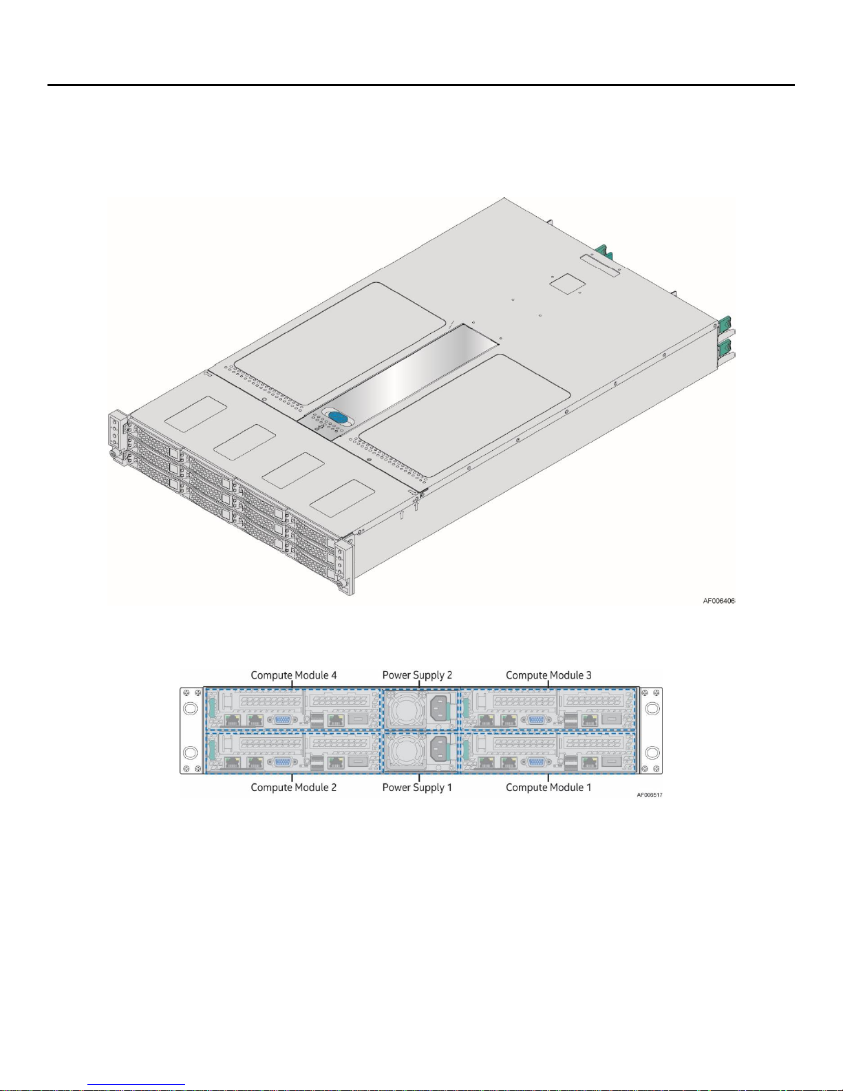
Figure 1. Server chassis overview (H2312XXKR2 SKU)
Figure 2. Server chassis rear view
12
Page 13

Intel® Server Chassis H2000G Product Family Service Guide
Feature
Description
Dimensions
(D x W x H)
H2312XXKR2
30.35 x 17.24 x 3.42 inches (771 x 438 x 86.9 mm)
H2216XXKR2
28.86 x 17.24 x 3.42 inches (733 x 438 x 86.9 mm)
H2224XXKR2
28.86 x 17.24 x 3.42 inches (733 x 438 x 86.9 mm)
H2224XXLR2
28.86 x 17.24 x 3.42 inches (733 x 438 x 86.9 mm)
Package dimensions
984 x 578 x 266 mm
Net weight
(package weight)
H2312XXKR2
21.5 kg (29.5 kg)
H2216XXKR2
20.5 kg (28.4 kg)
H2224XXKR2
20.6 kg (28.8 kg)
H2224XXLR2
20.6 kg (28.8 kg)
Compute module support
Intel® Compute Module HNS2600KP Product Family
Intel® Compute Module HNS2600TP Product Family
System fans
(1) – internal power supply fan for each installed power supply unit
(3) – fans for each compute module
Power supply options
1600 W AC Common Redundant Power Supply (CRPS), 80 PLUS* Platinum with
PFC (Power Factor Correction), supporting CRPS configuration
Storage bay options
H2312XXKR2
12x 3.5-inch SATA/SAS drive bays
H2216XXKR2
16x 2.5-inch SATA/SAS drive bays
H2224XXKR2
24x 2.5-inch SAS drive bays (8 x PCIe* SFF)
H2224XXLR2
24x 2.5-inch SAS drive bays (8 x PCIe* SFF)
2.1 Product Feature Overview
Table 2 summarizes the features of the product family.
Table 2. Product feature set
2.2 Server Chassis Components
This section helps identify the components of the product. The Quick Reference Label provided on the
chassis cover can also assist in identifying the components.
The Intel® Server Chassis H2000G product family supports four compute modules in the chassis. Figure 3
and Figure 4 show the whole chassis view with the power distribution module cover removed.
Note: The blank compute module bay must be covered by a dummy tray cover. When removed, keep the
dummy tray cover properly for future use. For more information on the dummy cover, see section 2.8.
Note: The compute module bay in the chassis requires either a compute module being installed and
powered up or a dummy tray cover installed to maintain proper thermal environment for the other running
compute modules in the same chassis. In case of a compute module failure, remove the failed compute
module, and replace with a dummy tray cover until the new compute module is installed.
13
Page 14
Intel® Server Chassis H2000G Product Family Service Guide
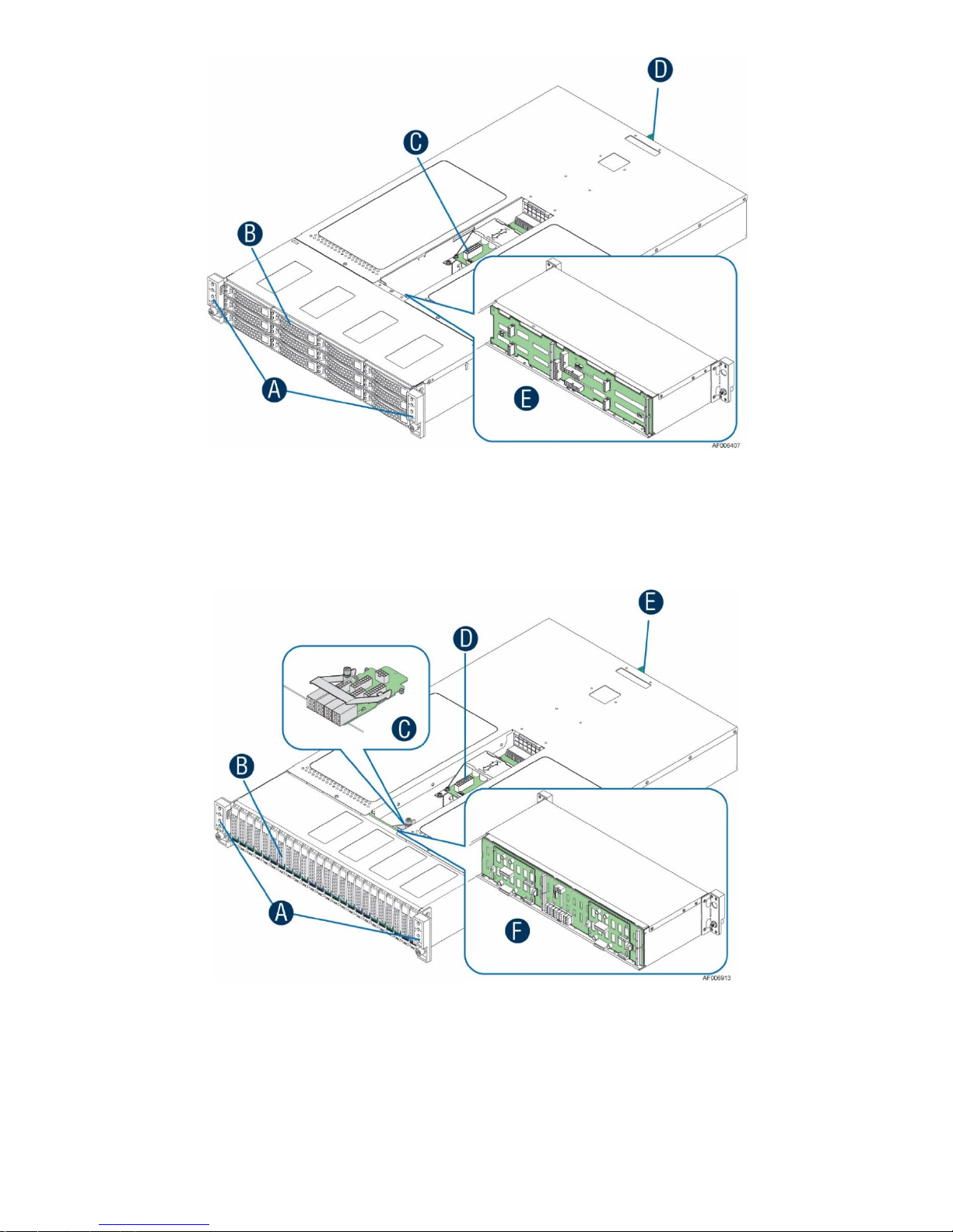
A – Front control panels
B – Drive bays
C – Power distribution modules
D – Power supply modules
E – Hot swap backplane (attached to
the drive cage)
A – Front control panels
B – Drive bays
C – Power interposer board (H2224KR2 only)
D – Power distribution module
E – Power supply modules
F – Hot swap backplane (attached to the drive cage)
Figure 3. Server chassis components (12 x 3.5” drive bay)
Figure 4. Server chassis components (24 x 2.5” drive bay)
14
Page 15

2.3 Drive Bays
Intel® Server Chassis H2000G Product Family Service Guide
Figure 5. Intel® Server Chassis H2312XXKR2 front view
Figure 6. Intel® Server Chassis H2216XXKR2 front view
Figure 7. Intel® Server Chassis H2224XXKR2/H2224XXLR2 front view
Each compute module has a dedicated drive array based on the backplane controller design. Figure 8, Figure
9, and Figure 10 show the schemes for the drive arrays corresponding to the compute modules.
Figure 8. Drive array scheme on the Intel® Server Chassis H2312XXKR2
Figure 9. Drive array scheme on the Intel® Server Chassis H2216XXKR2
15
Page 16

Intel® Server Chassis H2000G Product Family Service Guide
Figure 10. Drive array scheme on the Intel® Server Chassis H2224XXKR2/ H2224XXLR2
2.4 Front Control Panel
The server chassis contains two sets of control panels on the left and right rack handles. Each control panel
contains two sets of control buttons and LEDs for each compute module. Figure 11 and Figure 12 show the
locations and detailed view of the control panels.
Figure 11. Location of front control panel and LEDs
Figure 12. Detailed view of front control panel and LEDs
2.5 Front Bezel
The front bezel is available as an optional accessory for the server chassis. For information on removing and
installing the front bezel, see section 3.2.
16
Figure 13. Front bezel
Page 17

Intel® Server Chassis H2000G Product Family Service Guide
A – 80-pin miscellaneous signal connector
B – Power mate pin hole (to backplane)
C – Power mate pin hole (to backplane)
D
E – Power mate pin hole (to backplane)
A – Power edge connector (to top compute module power docking board)
B – 40-pin miscellaneous signal connector (to top compute module power docking board)
C – Front panel connector
D
E – Power edge connector (to bottom compute module power docking board)
F – Front panel connector
2.6 Backplane Interposer Board
The backplane interposer board (BIB) is only used in 24 x 2.5” drive chassis as the interposer between the
backplane and the power docking board to connect the power and miscellaneous signals from the
backplane to the compute modules.
(to backplane)
– Power mate pin hole (to backplane)
Figure 14. Backplane interposer board (front view)
– 40-pin miscellaneous signal connector (to bottom) compute module power docking board)
Figure 15. Backplane interposer board (back view)
17
Page 18

Intel® Server Chassis H2000G Product Family Service Guide
A – SATA/SAS connectors for node 1
B – SATA/SAS connectors for node 2
C – SATA/SAS connectors for node 3
D – SATA/SAS connectors for node 4
A – 2-blade compute module power connector for node 4
B – 2x40-pin bridge board connector for node 4
C – 2x9-pin power supply input connector
D
E – 2x7-pin power control cable connector
F – 2-blade compute module power connector for node 3
G
H – 2x40-pin bridge board connector for node 1
I – 20-pin front panel cable connector for nodes 1 and 3
J – 2-blade compute module power connector for node 1
K – 2x9-pin power supply input connector
L – 2x9-pin power supply input connector
M
N – 2-blade compute module power connector for node 2
O – 20-pin front panel cable connector for nodes 2 and 4
2.7 Hot-Swap SAS/SATA Backplane
The hot-swap SAS/SATA backplane serves as an interface between the mother board and the drives. The
following diagrams show the location for each connector found on the backplane.
2.7.1 3.5" Hot-Swap Backplane
Figure 16. 12 x 3.5" backplane components (front view)
– 2x9-pin power supply input connector
– 2x40-pin bridge board connector for node 2
– 2x40-pin bridge board connector for node 3
Figure 17. 12 x 3.5" backplane components (back view)
18
Page 19

Intel® Server Chassis H2000G Product Family Service Guide
A – SATA/SAS connectors for node 1
B – SATA/SAS connectors for node 2
C – SATA/SAS connectors for node 3
D – SATA/SAS connectors for node 4
A – 2-blade compute module power connector for node 4
B – 2x40-pin bridge board connector for node 4
C – 2x9-pin power supply input connector
D
E – 2x9-pin power control cable connector
F – 2-blade compute module power connector for node 3
G
H – 2x40-pin bridge board connector for node 1
I – 20-pin front panel cable connector for nodes 1 and 3
J – 2-blade compute module power connector for node 1
K – 2x9-pin power supply input connector
L – 2x9-pin power supply input connector
M
N – 2-blade compute module power connector for node 2
O – 20-pin front panel cable connector for nodes 2 and 4
2.7.2 16 x 2.5" Hot-Swap Backplane
Figure 18. 16 x 2.5" backplane components (front view)
– 2x7-pin power supply input connector
– 2x40-pin bridge board connector for node 3
Figure 19. 16 x 2.5" backplane components (back view)
19
– 2x40-pin bridge board connector for node 2
Page 20

Intel® Server Chassis H2000G Product Family Service Guide
A – SAS 0-3 SFF-8680 connectors (compute module 1)
B – SAS 4-5/PCIe* SFF 0-1 SFF 8639 connectors (compute module 1)
C – SAS 6-9 SFF-8680 connectors (compute module 3)
D
E – SAS 12-15 SFF-8680 connectors (compute module 2)
F – SAS 16-17/PCIe* SFF 4-5 SFF-8639 connectors (compute module 2)
G
H – SAS 22-23/PCIe* SFF 6-7 SFF-8639 connectors (compute module 4)
A – Power mate pin (to BIB)
B – Power mate pin (to BIB)
C – 80-pin miscellaneous signal connector (to BIB)
D
E – 2x7-pin power control cable connector (to PDB)
F – 2x4 pin P5V power cable connector (to PIB)
G
H
I – 100-pin bridge board connector
J – 100-pin bridge board connector
K – Power mate pin (to BIB)
L – Power mate pin (to BIB)
M
N
O
P – 12 V power connector (to PIB)
Q
R – Power mate pin (to BIB)
S – Power mate pin (to BIB)
2.7.3 SAS/PCIe* SFF Combo 24 x 2.5" Hot Swap Backplane
– SAS 10-11/PCIe* SFF 2-3 SFF-8639 connectors (compute module 3)
– SAS 18-21 SFF-8680 connectors (compute module 4)
Figure 20. 24 x 2.5" backplane components (front view)
– 100-pin bridge board connector
– 12 V power connector (to PIB)
– 12 V power connector (to PIB)
– 12 V power connector (to PIB)
– Power mate pin (to BIB)
– Power mate pin (to BIB)
– 100-pin bridge board connector
Figure 21. 24 x 2.5" backplane components (back view)
20
Page 21

Intel® Server Chassis H2000G Product Family Service Guide
2.8 Dummy Tray Cover
The dummy tray cover is shipped together with the chassis. It must be removed before installing the compute
module, or it must be restored if the compute module is not to be installed.
Figure 22. Dummy tray cover
21
Page 22

Intel® Server Chassis H2000G Product Family Service Guide
3. Hardware Installations and Upgrades
3.1 Before Beginning
Before working with the server product, pay close attention to the Safety Information
at the beginning of this document.
Warning: The transparent plastic protective films (if any) on the chassis top surface must be removed for
proper system cooling.
Note: Before servicing the server chassis, power down the server and unplug all peripheral devices and the
AC power cord.
3.1.1 Tools and Supplies Needed
Phillips* (cross head) screwdriver (#1 bit and #2 bit)
Needle nosed pliers
Anti-static wrist strap and conductive foam pad (recommended)
3.1.2 System Reference
All references to left, right, front, top, and bottom assume that the reader is facing the front of the chassis as
it would be positioned for normal operation.
3.2 Removing and Installing the Front Bezel
The server chassis supports the installation of an optional front bezel (iPC – A2UBEZEL). The bezel kit
includes a plastic lockable front bezel and multiple bezel snap-on badges allowing for OEM differentiation.
3.2.1 Bezel Snap-On Badges
The bezel kit provides three different bezel snap-on badges to allow for OEM differentiation; two different
size branding snap-on badges, and one decorative snap-on wave.
To mount a snap-on badge to the bezel, insert the badge hooks into the bezel and press to snap in place.
Figure 23. Installing snap-on badges to the front bezel
22
Page 23

Intel® Server Chassis H2000G Product Family Service Guide
To remove a snap-on badge from the bezel, squeeze the hooks at the rear of the snap-on badge to release it
(A) and remove the snap-on badge from the bezel (B) as pictured in Figure 24.
Figure 24. Removing snap-on badges from the front bezel
3.2.2 Removing the Front Bezel
To remove the front bezel, pull out the left side of the bezel from the rack handle (A) and rotate the left side
of the bezel away from the chassis to release the latches on the right side from the rack handle (B) as
pictured in Figure 25.
Figure 25. Removing the front bezel
23
Page 24

Intel® Server Chassis H2000G Product Family Service Guide
3.2.3 Installing the Front Bezel
Note: Before installing the front bezel, the rack handles must be installed.
To install the front bezel, lock the right side of the bezel to the rack handle (A) and press the left side of the
bezel towards the chassis until it clicks into place (B) as pictured in Figure 26.
Figure 26. Installing the front bezel
3.3 Removing and Installing the Power Distribution Module Cover
3.3.1 Removing the Power Distribution Module Cover
The server chassis must be operated with the power distribution module cover in place to ensure proper
cooling. Remove the cover to add or replace the components inside of the chassis. Before removing the cover,
power down the server and unplug all peripheral devices and the power cables.
Note: A non-skid surface or a stop behind the server chassis may be needed to prevent the server chassis
from sliding on the work surface.
To remove the power distribution module cover, refer to Figure 27.
1. Remove the screw (A).
2. Lift the cover from the front end to more than 45 degrees (B) and remove the cover.
Figure 27. Removing the power distribution module cover
24
Page 25

Intel® Server Chassis H2000G Product Family Service Guide
Latch
3.3.2 Installing the Power Distribution Module Cover
To install the power distribution module cover, refer to Figure 28.
1. Place the cover onto the chassis and slide forward until the front edge of the cover is pressed against the
back edge of the front drive bay (A).
2. Rotate the front end of the cover down to position and fix the cover with the screw (B).
Figure 28. Installing the power distribution module cover
3.4 Removing and Installing the Compute Module
Each compute module is identical in the chassis. They are designed for either “cold” or “hot” swappable. The
compute module can only be plugged from the rear chassis.
3.4.1 Installing the Compute Module
To install the compute module:
1. While pressing the latch, pull out the dummy tray cover (Figure 29).
Figure 29. Removing the dummy tray cover
2. Align and slide the compute module into the chassis.
Note: When the upper compute module is being inserted into the chassis, make sure its front edge overrides
the air duct edge of the lower compute module.
25
Page 26

Intel® Server Chassis H2000G Product Family Service Guide
3. While pressing the latch, push the compute module along the chassis rail until the latch locks in position
(Figure 30).
Figure 30. Installing the compute module
3.4.2 Removing the Compute Module
To remove the compute module:
1. While pressing the latch, pull out the handle with the compute module (Figure 31).
Figure 31. Removing the compute module
2. Restore the dummy tray cover (Figure 32).
Figure 32. Restoring the dummy tray cover
26
Page 27

Intel® Server Chassis H2000G Product Family Service Guide
3.5 Removing and Installing the Redundant Power Supply Unit
The server chassis is equipped with two redundant power supply units. Each of them can be hot-swappable.
Caution: Installing two power supply units with different wattage ratings in a server chassis is not supported.
Doing so does not provide power supply redundancy and results in multiple errors being logged.
3.5.1 Removing the Power Supply Unit
While pressing the latch, pull out the handle with the power supply unit (Figure 33).
Figure 33. Removing the power supply unit
3.5.2 Installing the Power Supply Unit
To install the power supply unit, refer to Figure 34.
1. Align and slide the power supply unit into the power cage.
2. While pressing the latch, push the power supply unit along the power cage rail until the latch locks in
position.
Figure 34. Installing the power supply unit
3.6 Installing a Hot-Swap Storage Device
Note: To maintain proper system cooling, all externally accessible drive bays must be populated with a carrier
mounted with a storage device (hard disk drive (HDD) or solid state drive (SSD)) or with a supplied drive blank.
27
Page 28

Intel® Server Chassis H2000G Product Family Service Guide
3.6.1 Installing a 3.5” Hard Disk Drive (HDD)
1. Remove the drive carrier from the chassis by pressing the green button and pulling open the lever (A)
and pull the carrier out of the drive bay (B) as pictured in Figure 35.
Figure 35. Installing a 3.5” HDD – removing the carrier
2. Remove the four screws securing the plastic drive blank to the carrier and remove the drive blank from
the carrier (C) as pictured in Figure 36.
Figure 36. Installing a 3.5” HDD – removing the drive blank
3. Insert the hard disk drive into the carrier (D). Verify the connector end of the drive is located towards the
back of the carrier and secure the drive to the carrier using the four screws as pictured in Figure 37.
Figure 37. Installing a 3.5” HDD – inserting the HDD
4. With the lever open, insert the carrier assembly into the chassis (E) and push in the lever to lock it into
place (F) as pictured in Figure 38.
Figure 38. Installing a 3.5” HDD – inserting the carrier assembly
28
Page 29

Intel® Server Chassis H2000G Product Family Service Guide
3.6.2 Installing a 2.5” Solid State Drive (SSD) into a 3.5” Carrier
The provided 3.5” drive blank can also be used as a 2.5” device bracket, allowing a 2.5” SSD to be installed
into a 3.5” device carrier.
Note: To maintain system thermals, all drive bays must be populated with a drive tray mounted with a HDD,
SSD, or supplied drive blank.
To install a 2.5” SSD into a 3.5” carrier, refer to Figure 39.
1. Remove the device carrier from the drive bay and remove the drive blank from the device carrier. For
instructions, see section 3.6.1.
2. Break off the small side tab from the drive blank, making the drive blank into a device bracket (d1).
3. Install the device bracket into the device carrier so that the hollow side of the device bracket is facing
down and secure the device bracket with the three screws (d2).
4. Turn the carrier assembly over.
5. Slide a 2.5" SSD into the device bracket and align the screw holes with the right and left rail (d3).
6. Secure the device using the four screws (d4).
7. Insert the carrier assembly into the chassis. For instructions, see section 3.6.1.
Figure 39. Installing a 2.5” SSD into a 3.5” drive blank
Note: Due to degraded performance and reliability concerns, the use of the 3.5” drive blank as a 2.5” device
bracket is intended to support SSD type storage devices only. Installing a 2.5” HDD into the 3.5” drive blank
is not supported.
29
Page 30

Intel® Server Chassis H2000G Product Family Service Guide
3.6.3 Installing a 2.5” Storage Device (HDD or SSD)
1. Remove the drive carrier from the chassis by pressing the green button, opening the lever (A) and pulling
the carrier out of the drive bay (B) as pictured in Figure 40.
Figure 40. Installing a 2.5” HDD or SSD – removing the carrier
2. Remove the four screws securing the plastic drive blank to the carrier (C), separate the arms of the carrier
slightly (D), and remove the drive blank from the carrier (E).
Figure 41. Installing a 2.5” HDD or SSD – removing the drive blank
3. Insert the storage device into the carrier (F). Verify the connector end of the storage device is located
towards the back of the carrier and secure the storage device to the carrier using the four screws as
pictured in Figure 42.
Figure 42. Installing a 2.5” HDD or SSD – inserting the 2.5” HDD or SSD
30
Page 31

Intel® Server Chassis H2000G Product Family Service Guide
4. With the lever open, insert the carrier assembly into the chassis (F) and push in the lever to lock it into
place (G) as pictured in Figure 43.
Figure 43. Installing a 2.5” HDD or SSD – inserting the carrier assembly
3.7 Replacing the 12 x 2.5" Backplane Board
3.7.1 Removing the 12 x 2.5" Backplane Board
1. Remove all hot-swap drive carriers, regardless of whether a drive is installed in the carrier.
2. Remove the power distribution module cover. For instructions, see section 3.3.1.
3. Disconnect all cables from the backplane board.
4. Remove the drive cage screws (A, B and C) and pull out the drive cage (D) as pictured in Figure 44.
31
Figure 44. Removing the drive cage
Page 32

Intel® Server Chassis H2000G Product Family Service Guide
5. Remove the screws from the backplane board (E) and detach the backplane board from the drive cage (F)
as pictured in Figure 45.
Figure 45. Removing the 12 x 2.5" backplane board from the drive cage
3.7.2 Installing the 2.5" Backplane Board
1. Attach the backplane board to the drive cage (A) and fix the backplane board with the screws (B) as
pictured in Figure 46.
Figure 46. Installing the 12 x 2.5" backplane board to the drive cage
32
Page 33

Intel® Server Chassis H2000G Product Family Service Guide
2. Install the drive cage to the chassis (C) and fix the drive cage with the screws (D, E and F) as pictured in
Figure 47.
Figure 47. Installing the drive cage to the chassis
3. Reconnect all cables to the backplane board.
4. Install the power distribution module cover. For instructions, see section 3.3.2.
5. Install all hot-swap drive carriers, if removed.
3.8 Replacing the 16 x 2.5" Backplane Board
3.8.1 Removing the 16 x 2.5" Backplane Board
1. Remove all hot-swap drive carriers, regardless of whether a drive is installed in the carrier.
2. Remove the power distribution module cover. For instructions, see section 3.3.1.
3. Disconnect all cables from the backplane board.
4. Remove the drive cage screws (A, B and C) and pull out the drive cage (D) as pictured in Figure 48.
33
Figure 48. Removing the drive cage
Page 34

Intel® Server Chassis H2000G Product Family Service Guide
5. Remove the screws from the backplane board (E) and detach the backplane board from the drive cage (F)
as pictured in Figure 49.
Figure 49. Removing the 16 x 2.5" backplane board from the drive cage
3.8.2 Installing the 16 x 2.5" Backplane Board
1. Attach the backplane board to the drive cage (A) and fix the backplane board with the screws (B) as
pictured in Figure 50.
Figure 50. Installing the 16 x 2.5" backplane board to the drive cage
34
Page 35

Intel® Server Chassis H2000G Product Family Service Guide
2. Install the drive cage to the chassis (C) and fix the drive cage with the screws (D, E and F) as pictured in
Figure 51.
Figure 51. Installing the drive cage to the chassis
3. Reconnect all cables to the backplane board.
4. Install the power distribution module cover. For instructions, see section 3.3.2.
5. Install all hot-swap drive carriers if removed.
3.9 Replacing the SAS/PCIe* SFF Combo 24 x 2.5" Hot Swap Backplane
3.9.1 Removing the SAS/PCIe* SFF Combo 24 x 2.5" Hot Swap Backplane
1. Remove all hot-swap drive carriers, regardless of whether a drive is installed in the carrier.
2. Remove the power distribution module cover. For instructions, see section 3.3.1.
3. Remove the power interposer board. For instructions, see section 3.11.1.
4. Disconnect all cables from the backplane board.
5. Remove the drive cage screws (A, B, and C) and pull out the drive cage (D) as pictured in Figure 52.
35
Figure 52. Removing the drive cage
Page 36

Intel® Server Chassis H2000G Product Family Service Guide
6. Disconnect the front panel cable from the backplane interposer board.
7. Remove the five screws from the backplane board (E), remove the screw and the bracket from the
bottom of the drive cage (F), and detach the backplane board from the drive cage (G) as pictured in Figure
53.
Figure 53. Removing the SAS/PCIe* SFF combo 24 x 2.5" hot swap backplane
3.9.2 Installing the SAS/PCIe* SFF Combo 24 x 2.5" Hot Swap Backplane
1. Attach the backplane board to the drive cage (A), fix the backplane board with the five screws (B), and
install the bracket with the screw (C) as pictured in Figure 54.
Figure 54. Installing the SAS/PCIe* SFF Combo 24 x 2.5" hot swap backplane
36
Page 37

Intel® Server Chassis H2000G Product Family Service Guide
2. Install the drive cage to the chassis (D) and fix the drive cage with the screws (E, F, and G) as pictured in
Figure 55.
Figure 55. Installing the drive cage to the chassis
3. Reconnect all cables to the backplane board.
4. Reconnect the front panel cable to the backplane interposer board.
5. Install the power interposer board. For instructions, see section 3.11.2
6. Install the power distribution module cover. For instructions, see section 3.3.2
7. Install all hot-swap drive carriers, if removed.
3.10 Removing and Installing the Power Distribution Module
3.10.1 Removing the Power Distribution Module
1. Remove the cover and the power supply units from the chassis.
2. Remove the power cables and PMBus* cable between the power distribution module and the backplane.
3. Remove the two screws (A) and slide the power distribution module and lift it (B) as pictured in Figure 56.
Figure 56. Removing the power distribution module
37
Page 38

Intel® Server Chassis H2000G Product Family Service Guide
3.10.2 Installing the Power Distribution Module
1. Slide in the power distribution module (A) and fix the module with the two screws (B) as pictured in
Figure 57.
Figure 57. Installing the power distribution module
2. Connect the power cables and the PMBus* cable to the power distribution module.
3. Close the cover and install the power supply units.
3.11 Replacing the Power Interposer Board
3.11.1 Removing the Power Interposer Board
Loosen the screw (A), rotate the bracket clockwise (B), and lift up the power interposer board (C) as pictured
in Figure 58.
Figure 58. Removing the power interposer board
38
Page 39

Intel® Server Chassis H2000G Product Family Service Guide
B
3.11.2 Installing the Power Interposer Board
Place the power interposer board into the compute module (A), rotate the bracket counterclockwise all the
way (B), and tighten the screw (C) as pictured in Figure 59.
Figure 59. Installing the power interposer board
3.12 Replacing the Front Control Panel Board
3.12.1 Removing the Front Control Panel Board
1. Remove the four screws on the back of the rack handle (A) as pictured in Figure 60. Be careful of the front
panel cable on the back.
Figure 60. Removing the front control panel assembly from the rack handle
2. Disconnect the cable from the front control panel board (B) as pictured in Figure 61.
Figure 61. Disconnecting the front panel cable
39
Page 40

Intel® Server Chassis H2000G Product Family Service Guide
3. Remove the two screws from the back of the front control panel board (C) and remove the board as
pictured in Figure 62.
Figure 62. Removing the front control panel board
3.12.2 Installing the Front Control Panel Board
1. Install the front control panel board to the panel shell with the two screws (A) as pictured in Figure 63.
Figure 63. Installing the front control panel board
2. Connect the cable to the front control panel board (B) as pictured in Figure 64.
Figure 64. Connecting the front panel cable
40
Page 41

Intel® Server Chassis H2000G Product Family Service Guide
3. Install the front control panel assembly to the rack handle with the four screws (C) as pictured in Figure
65.
Figure 65. Installing the front control panel assembly to the rack handle
41
Page 42

Intel® Server Chassis H2000G Product Family Service Guide
Parameter
Limits
Operating Temperature
+10 °C to +35 °C with the maximum rate of change not to exceed 10 °C per hour
Non-Operating Temperature
-40 °C to +70 °C
Non-Operating Humidity
90%, non-condensing at 35 °C
Acoustic noise
Sound power: 7.0 BA with hard disk drive stress only at room ambient temperature (23 ± 2 °C)
Shock, operating
Half sine, 2 g peak, 11 msec
Shock, unpackaged
Trapezoidal, 25 g velocity change 175 inches/second (80 lbs to < 100 lbs)
Vibration, unpackaged
5 Hz to 500 Hz, 2.20 g RMS random
Shock and vibration, packaged
International Safe Transit Association (ISTA) Test Procedure 3A
ESD
±12 KV except I/O port ±8 KV per Intel® Environmental Test Specification
System Cooling Requirement
1600 W maximum – 5459 BTU/hour
2130 W maximum – 7268 BTU/hour
Appendix A. Technical Reference
A.1. System Environmental Specifications
The following table defines the system level operating and non-operating environmental limits.
Table 3. System environmental limits summary
Disclaimer Note: Intel ensures the unpackaged server board and system meet the shock requirement
mentioned above through its own chassis development and system configuration. It is the responsibility of
the system integrator to determine the proper shock level of the board and system if the system integrator
chooses different system configuration or different chassis. Intel Corporation cannot be held responsible, if
components fail or the server board does not operate correctly when used outside any of its published
operating or non-operating limits.
42
Page 43

Intel® Server Chassis H2000G Product Family Service Guide
Appendix B. Regulatory and Compliance Information
Refer to the Server Products Regulatory and Safety document for the product regulatory compliance
reference. The document can be downloaded from
http://www.intel.com/content/www/us/en/support/boards-and-kits/000007675.html.
43
Page 44

Intel® Server Chassis H2000G Product Family Service Guide
Appendix C. Getting Help
If there is an issue with the server chassis, follow these steps to obtain support:
1. Visit http://www.intel.com/p/en_US/support/contactsupport.
This web page provides 24x7 support to get the latest and most complete technical support information
on all Intel® Enterprise Server and Storage Platforms. Information available at the support site includes:
Latest BIOS, firmware, drivers, and utilities.
Product documentation and installation and quick start guides.
Full product specifications, technical advisories, and errata.
Compatibility documentation for memory, hardware add-in cards, and operating systems.
Server and chassis accessory parts list for ordering upgrades or spare parts.
A searchable knowledgebase to find for product information throughout the support site.
2. If a solution cannot be found at Intel’s support site, send an email to Intel’s technical support center using
the online form available at http://www.intel.com/support/feedback.htm?group=server.
3. Lastly, contact an Intel support representative using one of the support phone numbers available at
http://www.intel.com/support/feedback.htm?group=server (charges may apply).
Intel also offers Channel Program members around-the-clock 24x7 technical phone support on Intel® Server
Boards, Intel® Server Chassis, Intel® RAID Controller cards, and Intel® Server Management at
http://www.intel.com/content/www/us/en/secure/technology-provider/overview.html.
Note: Access to the 24x7 number requires a login to the reseller site.
C.1. Warranty Information
To obtain warranty information, visit http://www.intel.com/p/en_US/support/warranty.
44
 Loading...