

Page 1

TECHNICAL MANUAL
Of
Intel H110 Express Chipset
Based Mini-ITX M/ B
NO. G03-NF693-F
Revision: 3.0
Release date: July 19, 2017
Trademark:
* Specifications and Informati on cont a ined in t his docu me nt ation are furnished for informatio n u se only, and are
subject to change at any time without notice, and should not be construed as a commitment by manufacturer.
Page 2

i
Environmental Pr otecti on Announcement
Do not dispose this electronic device into the trash while discarding. To minimize
pollution and ensure environment protection of mother earth, pl ease recycle.
Page 3

ii
ENVIRONMENTAL SAFETY INSTRUCTION ...................................................................... iii
USER’S NOTICE .................................................................................................................. iv
MANUAL REVISION INFORMATION .................................................................................. iv
ITEM CHECKLIST ................................................................................................................ iv
CHAPTER 1 INTRODUCTION OF THE MOTHERBOARD
1-1 FEATURE OF MOTHERBOARD ................................................................................ 1
1-2 SPECIFICATION ......................................................................................................... 2
1-3 LAYOUT DIAGRAM .................................................................................................... 3
CHAPTER 2 HARDWARE INSTALLATION
2-1 JUMPER SETTING ..................................................................................................... 8
2-2 CONNECTORS AND HEADERS ................................................................................ 13
2-2-1 CONNECTORS ............................................................................................. 13
2-2-2 HEADERS ..................................................................................................... 18
CHAPTER 3 INTRODUCING BIOS
3-1 ENTERING SETUP ..................................................................................................... 24
3-2 BIOS MENU SCREEN ................................................................................................ 25
3-3 FUNCTION KEYS ....................................................................................................... 25
3-4 GETTING HELP .......................................................................................................... 26
3-5 MENU BARS ............................................................................................................... 26
3-6 MAIN MENU ................................................................................................................ 27
3-7 ADVA NCED MENU ..................................................................................................... 28
3-8 CHIPSET MENU .......................................................................................................... 39
3-9 SECURITY MENU ....................................................................................................... 42
3-10 BOOT MENU ............................................................................................................... 43
3-11 SAVE & EXIT MENU ................................................................................................... 44
TABLE OF CONTENT
Page 4

iii
Environmental Safety I ns truction
Avoid the dusty, humidity and temperature extremes. Do not place the product in
any area where it may become wet.
0 to 40 centigrade is the suitable temperature. (The temperature comes from the
request of the chassis and thermal solution)
Generally speaking, dramatic changes in temperature may lead to contact
malfunction and crackles due to constant thermal expansion and contraction from
the welding spots’ that connect components and PCB. Computer should go
through an adaptive phase before it boots when it is moved from a cold
environment to a warmer one to avoid condensation phenomenon. These water
drops attached on PCB or the surface of the components can bring about
phenomena as minor a s computer instabi lity resulted fr om corrosi on and oxi dation
from components and PCB or as major as short circuit that can burn the
components. Suggest starting the computer until the temperature goes up.
The increasing temperature of the capacitor may decrease the life of computer.
Using the close case may decrease the life of other device because the higher
temperature in the inner of the case.
Attention to the heat sink when you over-clocking. The higher temperature may
decrease the life of the device and burned the capacitor.
Page 5

iv
USER’S NOTICE
COPYRIGHT OF THIS MANUAL BELONGS TO THE MANUFACTURER. NO PART OF THIS MANUAL,
INCLUDING THE PRODUCTS AND SOFTW ARE DESCRIBED I N IT MAY BE REPRO DUCED, T RANSMITTED
OR TRANSLATED INTO ANY LANGUAGE IN ANY FORM OR BY ANY MEANS WITHOUT WRITTEN
PERMISSION OF THE MANUFACTURER.
THIS MANUAL CONTAINS ALL INFORMATION REQUIRED TO USE THIS MOTHER-BOARD SERIES AND WE
DO ASSURE THIS MANUAL MEETS USER’S REQUIREMENT BUT WILL CHANGE, CORRECT ANY TIME
WITHOUT NOTICE. MANUFACTURER PROVIDES THIS MANUAL “AS IS” WITHOUT WARRANTY OF ANY
KIND, AND WILL NOT BE LIABLE FOR ANY INDIRECT, SPECIAL, INCIDENTAL OR CONSEQUENTIAL
DAMAGES (INCLUDING DAMAGES FOR LOSS OF PROFIT, LOSS OF BUSINESS, LOSS OF USE OF DATA,
INTERRUPTION OF BUSINESS AND THE LIKE).
PRODUCTS AND CORPORATE NAMES APPEARING IN THIS MANUAL MAY OR MAY NOT BE
REGISTERED TRADEMARKS OR COPYRIGHTS OF THEIR RESPECTIVE COMPANIES, AND THEY ARE
USED ONLY FOR IDENTIFICATION OR EXPLANATION AND TO THE OWNER’S BENEFIT, WITHOUT
INTENT TO INFRINGE.
Manual Revision Information
Reversion Revision History Date
2.0 Second Edition November 17, 2016
3.0 Third Edition July 19, 2017
Item Checklist
Motherboard
DVD for motherboard utilities
User’s Manual
Cable(s)
I/O Back panel shield
Page 6

1
Chapter 1
Introduction of the Motherboard
1-1 Fea ture of Motherboard
Intel® H110 express chipset
Support LGA 1151 CPU socket Intel® Core™ i7 processors / Intel® Core™ i5
processors / Intel® Core™ i3 processors / Intel® Pentium™ processors , Intel®
Celeron™ processors (TDP ≤65 W).
Support 2* DDR4 2133MHz SO-DIMM up to 32GB and dual channel function
Integrated with 2* Realtek Gigabit Ethernet LAN chip
Integrated with RealTek ALC662-VD-GR 6-channel HD Audio Codec
Support USB 3.0 data transport demand
Support 2 * SATAIII (6Gb/s) Devices
Support 1* Display port & 1* HDMI port
Support 1* PCIE 2.0 x16 slot
Support 1* full-size Mini-PCIE/MSATA slot
Support1* 1* M.2 Socket 3 slot for M-key type 2242/2260 SATA SSD
Support Smart FAN function
Supports ACPI S3 Function
Compliance with ErP Standard
Support Watchdog Timer Technology
Page 7

2
1-2 Specification
Spec
Description
Design
Mini-ITX form factor 6 layers; PCB size: 17.0x17.0cm
Chipset
Intel H110 Express Chipset
CPU Socket
Support Intel® LGA 115 1 Socket Core™ i7 processors, Intel®
Core™ i5 processors, Intel® Core™ i3 processors, Intel
®
Pentium™ processors, Intel® Celeron™ processors
* for detailed CPU support information please visit our website
Memory Slot
2*DDR4 SO-DIMM slot
Support DDR4 2133 MHz SO-DIMM up to 32GB
Support dual channel function
Expansion Slot
1* PCIE x 16 slot
1* Full-size Mini-PCIE/ MSATA shared slot (MPE1)
Storage
2* SATA III 6G/s connector
1 * full-size Mini-PCIE/ MSATA shared slot (MPE1)
1* M.2 Socket 3 slot (M-key, support type 2242/2260
SATA
SSD)
Gigabit LAN Chip
Integrated with 2* Real tek RTL811 1G Gigabit PCI-E LAN
chip
Support Fast Ethernet LAN func ti on of providing
10/100/1000Mbps Ethernet data transfer rate
Audio Chip
Realtek ALC662-VD-GR 5.1 ch ann el Audio Codec integrated
Audio driver and utility included
BIOS
AMI 64Mb Flash ROM
Multi I/O
Rear Panel I/O:
4* Serial port connector(COM1_COM2/COM3_COM4,
COM1 supports RS232/422/485 function )
1* Display port
1* HDMI port
4* USB 3.0 port
Page 8
3
2* RJ-45 LAN port
1*3-jack audio connector (Line-in, Line-out, MIC)
Internal I/O Connectors& Headers:
1 *24-pin main power connector
1 * 4-pin 12V power connector
1* CPUFAN connector & 1* SYSFAN connect or
1*Front panel audio header
1* SPDIF-out header
1*Front panel header
2 * 9-Pin USB 2.0/1.1 header for 4* USB 2. 0/ 1.1 por t s
1 * PS2 Keyboard & Mouse header
1* SMBUS header
1* GPIO header
2* Serial port header (COM5/6,COM5 is optional to support
RS232/422/485)
1* Jumper & Header Combo Block (JP1)
1* EDP connector
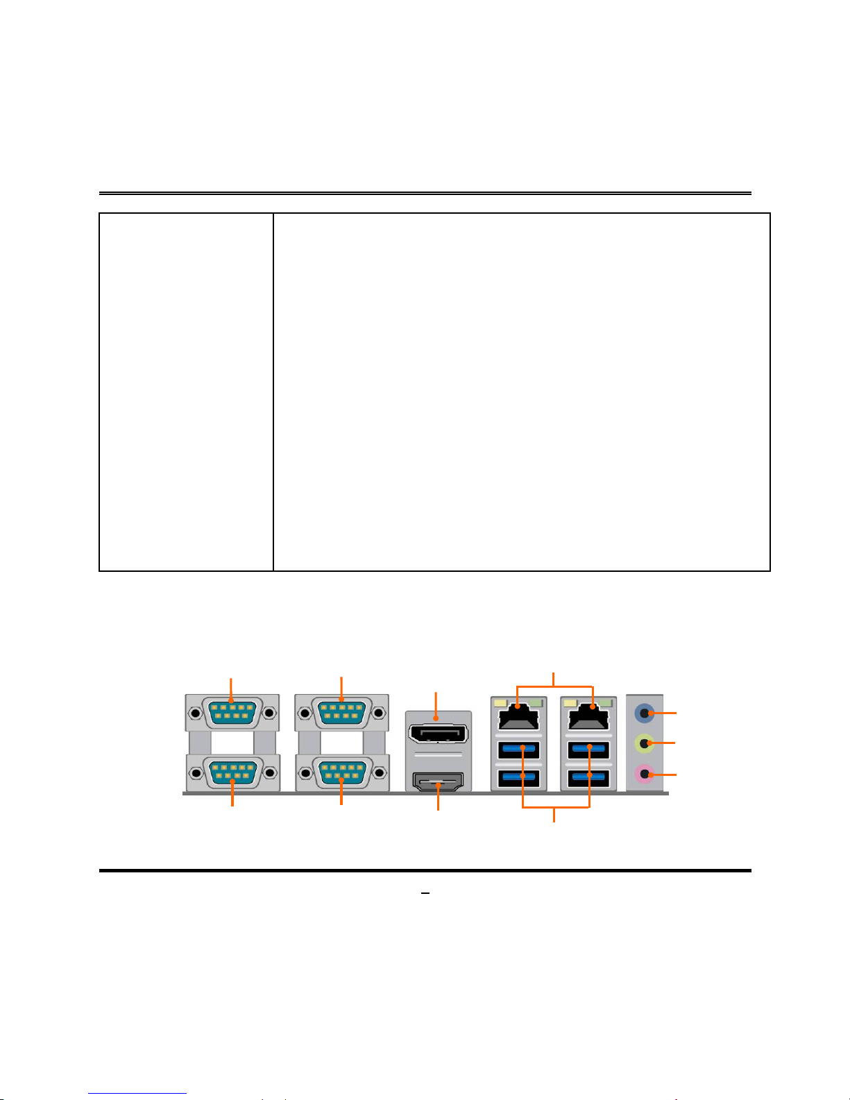
1-3 Layout Diagram
Rear IO Diagram
Serial Port
(COM1)
Serial Port
(COM2)
Serial Port
(COM3)
Serial Port
(COM4)
Display Port
HDMI Port
RJ-45 LAN Ports
USB 3.0 Ports
Line-IN
Line-OUT
MIC-IN
Page 9
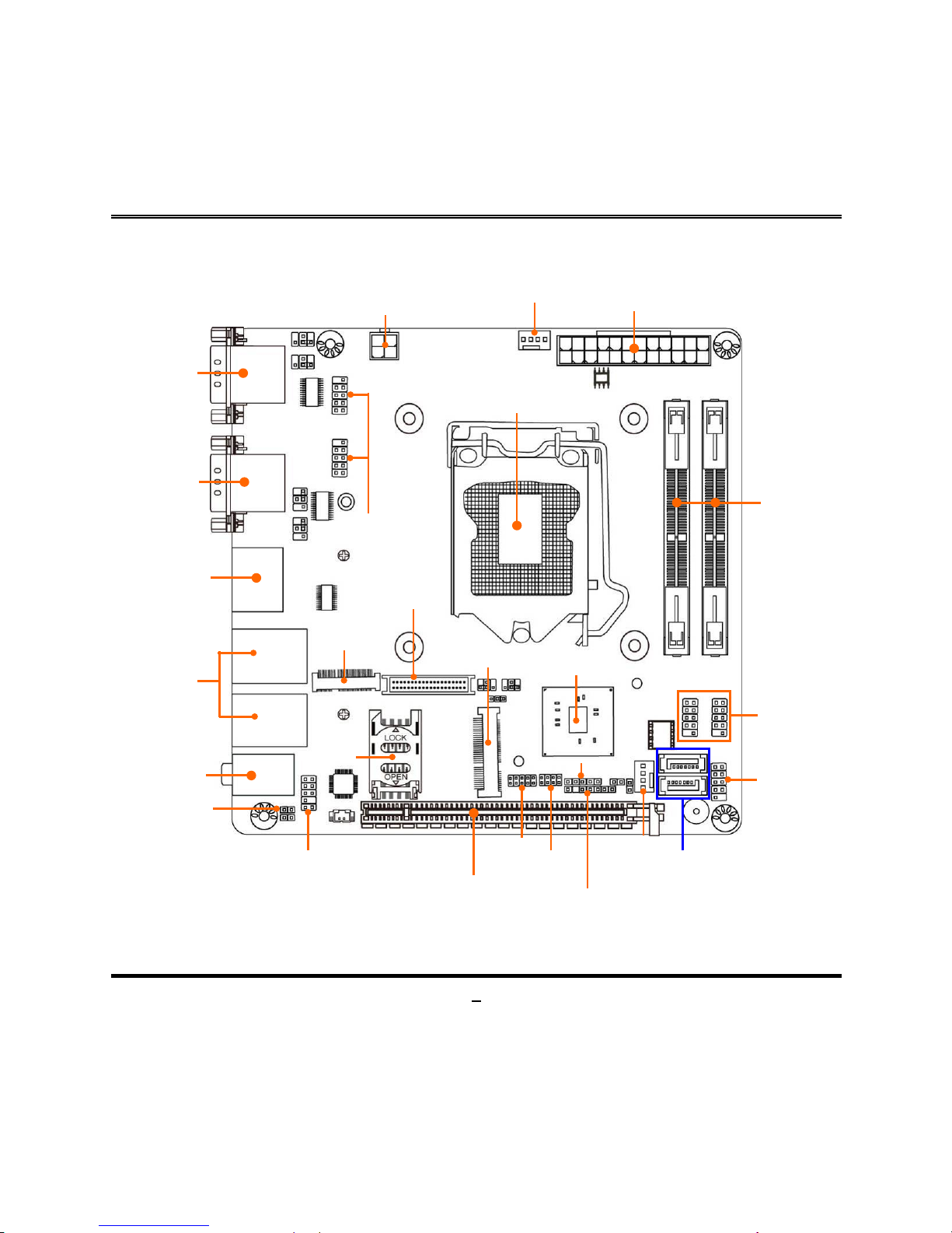
4
Motherboard Internal Diagram-Front
Note: SIM card slot only work when c ompati bl e SIM card installed & 3G LAN card installed in MPE1 Mini-PCIE slot.
Serial Ports
Serial Ports
RJ-45 LAN Ports
Over
USB 3.0 Ports
Display Port
over HDMI Port
Audio
Connectors
ATX Power
Connector
ATX 12V
Power Connector
CPUFAN Header
LGA 1151
CPU Socket
Intel H110 Chipset
PCI Express 2.0 x 16 Slot (PCIE1)
USB 2.0
Headers
Front Panel
Audio Header
Serial Port Headers
EDP
Connector
*DDR4 SODIMM Slot
(SODIMM1/2)
SATAIII Ports
(SATA1/2)
SYSFAN1 Header
Front Panel
Header
*SIM Card
Slot
*Full-size
Mini-PCIE/MSATA
Slot (MPE1)
SPDIF_OUT
Header
GPIO Header
JP1: Jumper & Header
Combo Block
PS/2 Keyboard & Mouse
Header
M.2 Socket 3
Connector
(MH1/2)
SUBUS Header
Page 10
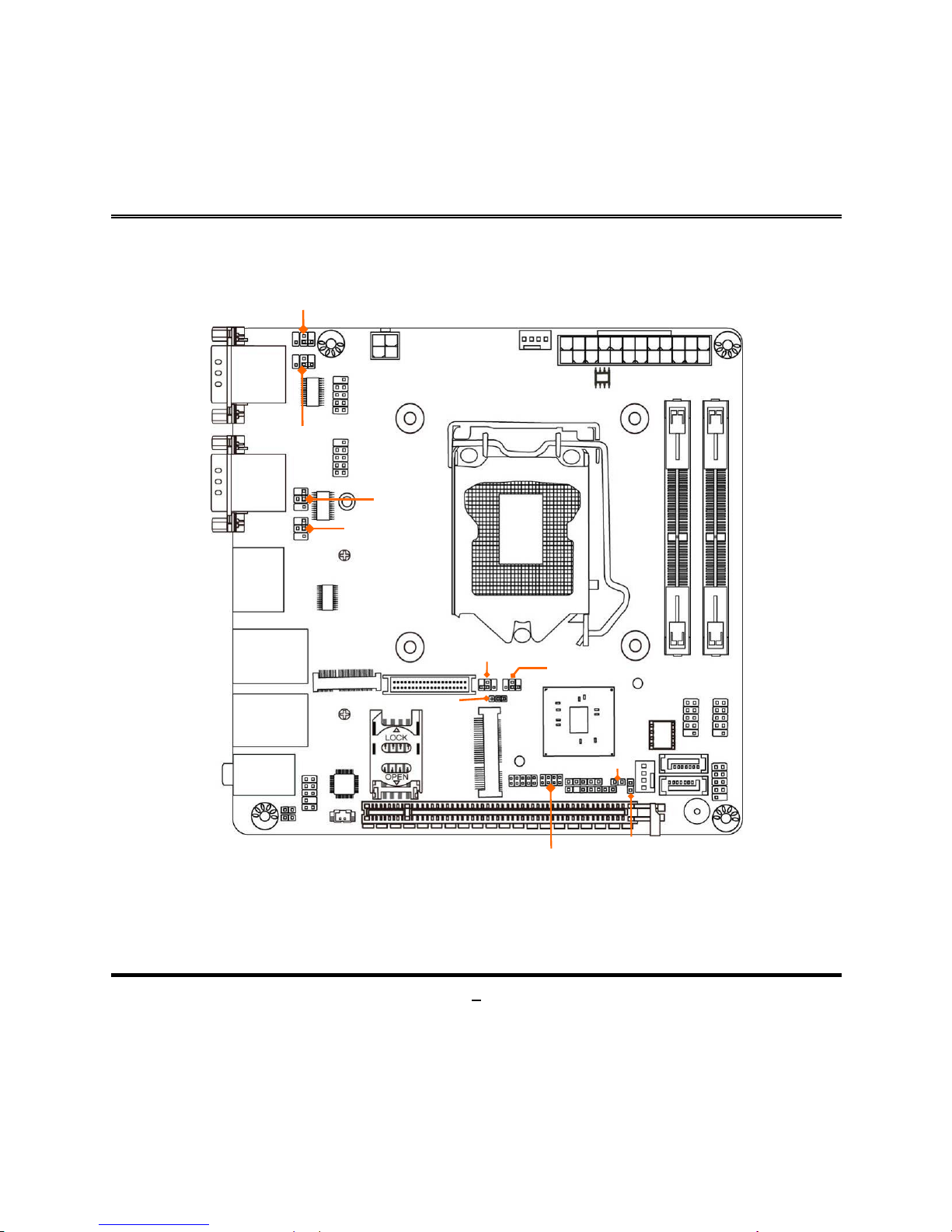
5
Motherboard Jumper Position
JCOMP2
JP2
JCOMP1
JCOMP3
JCOMP4
EDP_BKPWR
EDP_LCDPWR
JP1: Jumper & Header
Combo Block
MPE_PWR
JP_TEST
Page 11

6
Connectors
Connector
Name
ATXPWR1
24-Pin ATX Main Power Connector
ATX12V1
4-Pin 12V Power Connector
COM1_COM2/COM3_COM4
Serial Port COM Connector X4
DP_HDMI1
Top: Display Port Connector
Bottom: HDMI Port Connector
UL1/UL2
Top:RJ-45 LAN Connector X2
Middle & Bottom: USB 3.0 Port Connector X4
AUDIO1
Top: Line-in Connector
Middle: Line-out Connector
Bottom: MIC Connector
SATA1/2
SATAIII Connector
EDP
EDP Connector
SYSFAN,CPUFAN
FAN Connector X2
Headers
Header
Name
Description
FP_AUDIO1
Front Panel Audio Header
9-pin Block
SPDIFOUT1
HDMI_SPDIF Out Header
2-pin Block
FP1
Front Panel Header(PWR LED/ HD
LED/Power Button /Re set )
9-pin Block
USB1/2
USB Header X2
9-pin Block
PS2KBMS
PS2 Keyboard & Mouse Header
6-pin Block
SMBUS
SMBUS Header
5-pin Block
GPIO1
GPIO Header
10-pin Block
JP1
Pin(5&6):LAN1 Activity LED Header
Pin(7&8):LAN2 Activity LED Header
8-pin Block
COM5/6
Serial Port Header
9-pin Block
Page 12

7
Jumper
Jumper
Name
Description
JCOMP1
COM1 Port Pin9 Function Select
4-pin Block
JCOMP2
COM2 Port Pin9 Function Select
4-pin Block
JCOMP3
COM3 Port Pin9 Function Select
4-pin Block
JCOMP4
COM4 Port Pin9 Function Select
4-pin Block
JBAT
Clear CMOS RAM Settings
2-pin Block
JP2
ME_Features Select
2-pin Block
MPE_PWR
MPE1 Slot MPE_PWR VCC 3.3V/3.3VSB Select
3-pin Block
JP1
Pin(1-2): Case Open Message Display Function
Pin(3-4): ATX Mode / AT Mode Select
8-pin Block
EDP_BKPWR
EDP Backlight VCC 3.3V/5V/12V Select
4-pin Block
EDP_LCDPWR
EDP Panel Backlight VCC 3.3V/5V/12V Select
4-pin Block
Page 13
8
Chapter 2
Hardware Installation
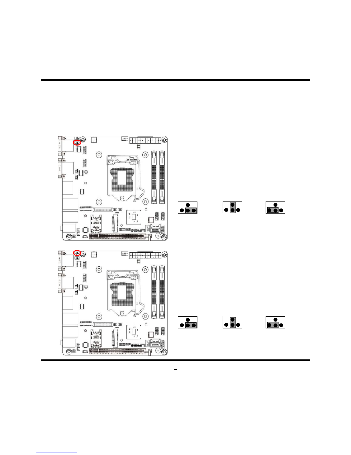
2-1 Jumper Setting
JCOMP1 (4-pin): COM1 Port Pin9 Function Select
1 3 5
4
6
2
6
4
2
5
3
1
6 4 2
5
3
1
JCOMP1→COM1 Port
Pin
-9
2-4 Closed:
Pin9=RING;
3-4 Closed:
Pin9=5V;
4-6 Closed:
Pin9=12V.
JCOMP2 (4-pin): COM2 Port Pin9 Function Select
1 3 5
4
6
2
6
4
2
5
3
1
6 4 2
5
3
1
JCOMP
2→COM2
Port Pin-9
2-4 Closed:
Pin9=RING;
3-4 Closed:
Pin9=5V;
4-6 Closed:
Pin9=12V.
Page 14
9
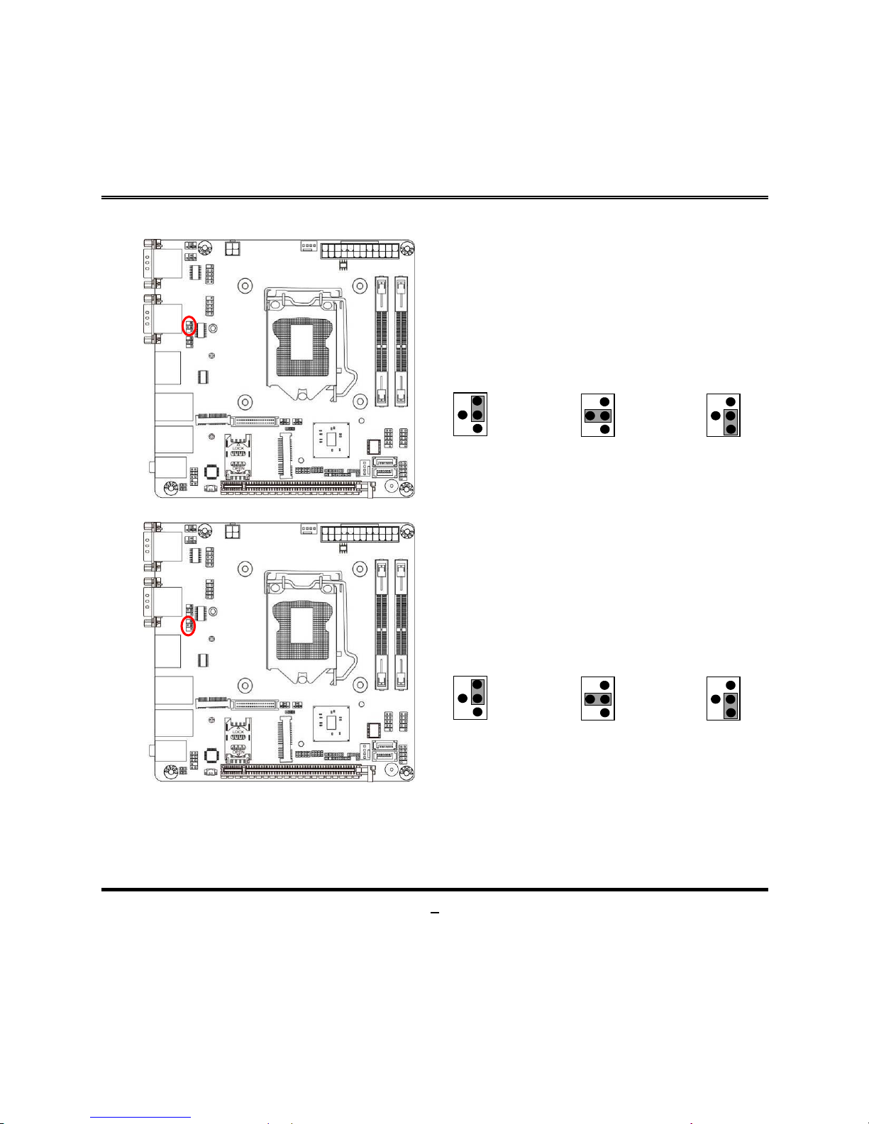
JCOMP3 (4-pin): COM3 Port Pin9 Function Select
6
4
2
3
1
5
1
2
4
6
3
5
2
4
6
1
3
5
2-4 Closed:
Pin9=RING;
3-4 Closed:
Pin9=5V;
4-6 Closed:
Pin9=12V.
JCOMP3→COM3 Port Pin-9
JCOMP4 (4-pin): COM4 Port Pin9 Function Select
6
4
2
3
1
5
1
2
4
6
3
5
2
4
6
1
3
5
2-4 Closed:
Pin9=RING;
3-4 C
losed:
Pin9=5V;
4-6 C
losed:
Pin9=12V.
JCOMP
4→COM4 Port
Pin-9
Page 15
10
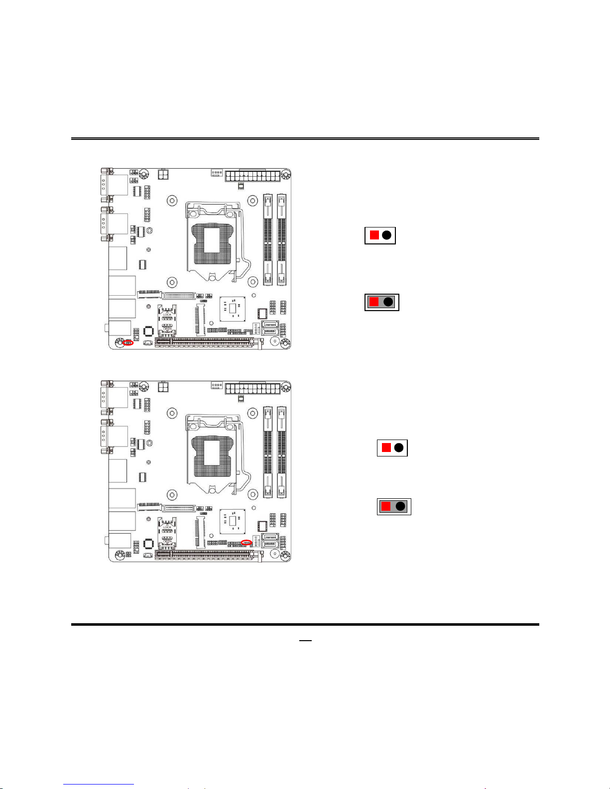
JBAT (2-pin): Clear CMOS RA M Settings
JBAT→Clear CMOS
1
2
1
2
1-2
Open: Normal (Default);
1-2 Closed:Clear CMOS Settings.
JP2 (2-pin): ME Features Select
1
2
1
2
JP2→ME Features Select
1
-2 Open: Enable ME Features;
1-2 Closed: Disable ME Features.
Page 16

11
MPE_PWR (3-pin): MPE1 Slot VCC 3.3V/3.3 VSB Select
2-3 Closed: MPE1 Slot VCC= 3.3VSB.
MPE_PWR
→
MPE1 Slot VCC
1
-2 Closed: MPE1 Slot
VCC= 3.3V;
1
3
1
3
Pin (1-2) of JP1 (8-pin):Case Open Message Display Function Select
2
Pin1
2
Pin1
4
3
3
4
5
6
6
5
Pin(1-2) of JP1→Case Open Detect
1-2 Open: Normal (Default);
1-2 Close: Case Open Detect
Function Selected.
7
8
8
7
Pin (1-2) Close: When Case open function pin short to GND, the Case open
function was detected. When Used, needs to enter BIOS and enable ‘Case Open
Detect’ function. In this case if your case is removed, next time when you restart
your computer, a message will be displayed on screen to inform you of this.
Page 17

12
Pin (3-4) of JP1 (8-pin): ATX Mode/ AT Mode Select
2
Pin1
2
Pin1
4
3
3
4
5
6
6
5
7
8
8
7
Pin(3-4) of JP7→ATX/AT Mode Select
3-4 Open: ATX Mode Selected (Default);
3-4 Close : AT Mode Selected.
*ATX Mode Selected: Press power button to power on after power input ready;
AT Mode Selected: Directly power on as power input ready.
EDP_BKPWR (4-pin): EDP Backlight VCC 3.3V/5V/12V
1 3 5
4
6
2
6
4
2
5
3
1
6 4 2
5
3
1
EDP_BKPWR→EDP Backlight VCC
2-4 Closed:
EDP Backlight
VCC =3.3V;
3
-4 Closed:
EDP Backlight
VCC =5V;
4-6 Closed:
EDP Backlight
VCC =12V;
Page 18

13
EDP_ LCDPWR (4-pin): EDP LCD Panel VCC 3.3V/5V/12V
1 3 5
4
6
2
6
4
2
5
3 1 6 4 2
5
3
1
EDP_LCDPWR→EDP LCD Panel VCC
2-4 Closed:
EDP LCD
VCC =3.3V;
3-4 Closed
:
EDP LCD
VCC =5V;
4-6 Closed:
EDP LCD
VCC =12V;
2-2 Connectors and Headers
2-2-1 Connectors
(1) Rear Panel Connectors
Serial Port
(COM1)
Serial Port
(COM2)
Serial Port
(COM3)
Serial Port
(COM4)
Display Port
HDMI Port
RJ-45 LAN Ports
USB 3.0 Ports
Line-IN
Line-OUT
MIC-IN
Page 19

14
Icon Name Function
Serial Port
Mainly for user to connect external MODEM or other
devices that supports
Serial Communications Interface.
*Note: COM1 supports RS232/422/485 function.
Display Port
To the system to corresponding display device with
compatible display port cable.
HDMI Port
To connect display device that support HDMI
specification.
RJ-45 LAN Port
This connector is standard RJ-45 LAN jack for
Network connection.
USB 3.0 Port
To connect USB keyboard, mouse or other devices
compatible with USB specification. USB 3.0 ports
supports up to 5Gbps data transfer rate.
Audio Connectors
BLUE:
Line-in Connector
GREEN: Line-out Con nect or
PINK : MIC Connector
Page 20

15
(2) COM1 (9-pin Block): RS232/422/485 Port
COM1 port can function as RS232/422/485 port. In normal settings COM1 functions
as RS232 port. With compatible COM cable COM1 can function as RS422 or RS 485
port. User also needs to go to BIOS to set ‘Transmission Mode Select’ for CO M1
at first, before using specialized cable to connect different pins of this port.
(3) ATXPWR1 (24-pin block): Power Connector
Page 21

16
(4) ATX12V1 (4-pin block): ATX12V Type Power Connector
(5) SATA1/SATA2 (7-pin): SATA III Port connector
SATA1&SATA2 are high-speed SATAIII port that supports 6 GB/s transfer rate.
Pin No.
Defnition
1
GND
2
TXP
3
TXN
4
GND
5
RXN
6
RXP
7
GND
Page 22

17
(6) EDP(40-pin): EDP Connector
Pin 1
Pin21
Pin No.
Pin Define
Pin No.
Pin Define
Pin 1
NC
Pin 21
NC
Pin 2
GND
Pin 22
NC
Pin 3
EDP_DATA3N
Pin 23
GND
Pin 4
EDP_DATA3P
Pin 24
GND
Pin 5
GND
Pin 25
GND
Pin 6
EDP_DATA2N
Pin 26
GND
Pin 7
EDP_DATA2P
Pin 27
EDP_HPD
Pin 8
GND
Pin 28
GND
Pin 9
E DP_DATA1N
Pin 29
GND
Pin 10
EDP_DATA1P
Pin 30
GND
Pin 11
GND
Pin 31
GND
Pin 12
EDP_DATA0N
Pin 32
LCD_BKLT_EN
Pin 13
EDP_DATA0P
Pin 33
LCD_BKLT_PWM
Pin 14
GND
Pin 34
Option
Pin 15
EDP_AUXP
Pin 35
NC
Pin 16
EDP_AUXN
Pin 36
LCD_BKLT_PWR
Pin 17
GND
Pin 37
LCD_BKLT_PWR
Pin 18
LCD_VCC
Pin 38
LCD_BKLT_PWR
Pin 19
LCD_VCC
Pin 39
LCD_BKLT_PWR
Pin 20
LCD_VCC
Pin 40
NC
Page 23

18
(7) CPUFAN/SYSFAN (4-pin): Fan Connector
2-2-2 Headers
(1) FP_AUDIO1 (9-pin): Line-Out, MIC-In Header
This header connects to Front Panel Line-out, MIC-In connector with cable.
MIC2_L
MIC2_R
LINE_OUT_R
SENSE
MIC_JD
Pin 1
2
GND
DETECT
LINE_OUT_L
LINE_OUT_JD
Page 24

19
(2) SPDIFOUT1 (2-pin): HDMI-SPDIF Out header
Pin1
SPDIF_OUT
GND
(3) FP1 (9-pin): Front Panel Header
HDD LED+
GND
HDD LED-
GND
RSTSW
PWRBTN
Pin 1
2
VCC
PWR LED+
PWR LED -
Page 25

20
(4) USB1/USB2 (9-pin): USB 2.0 Port Headers
VCC
NC
+DATA
Pin 1
-DATA
VCC
GND
GND
+DATA
-DATA
2
(5) PS2KBMS (6-pin): PS/2 Keyboard & Mouse Header
GND
KB_CLK
KB_DATA
Pin1
MS_DATA
VCC
MS_CLK
Page 26

21
(6) SMBUS (4-Pin): SMBUS Header
SMBUS_CLK
VCC3
Pin1
SMBUS_DATA
GND
SMBUS_ALERT
(7) GPIO1(10-pin): GPIO Header
9
GPIO81
GND
GPIO83 GPIO85
GPIO87
GPIO80
GPIO82
2
Pin 1
10
VCC
GPIO84
GPIO86
Page 27

22
(8) COM5/COM6 (9-pin): RS232(/422/485) Serial Port Header
Pin NO.
RS232
*RS422
(COM5
)
*RS485
(COM5)
Pin 1
DCD
TX-
DATA
-
Pin 2
DSR
NC
NC
Pin 3
RXD
TX+
DATA+
Pin 4
RTS
NC
NC
Pin 5
TXD
RX+
NC
Pin 6
CTS
NC
NC
Pin 7
DTR
RX-
NC
Pin 8
RI
NC
NC
Pin 9
GND
GND
GND
COM5 is optional to support RS232/422/485 function.
COM6 only supports RS232 function.
*Notice: COM5 servers as RS232 serial port header in most cases.RS422 &
RS485 function is only optional to customized models. User also needs to go to BIOS
to set ‘Transm issio n Mode Select’ for COM5 as [RS422] or [RS485] (only supported
by customized BIOS version )for boards that support RS422/485 function before
connecting compatible COM cable to COM5 header.
Page 28

23
(9) Pin( 5-6) & Pin(7-8) of JP1 (8-pin): LAN Activity LED Headers
Pin1
7
8
JP1: Pin(5-6)→LAN1 Activity LED
JP1: Pin(7-8)→LAN2 Activity LED
LAN1LED-
LAN1LED+
LAN2LED+
LAN2LED-
2
Page 29

24
Chapter 3
Introducing BIOS
Notice! The BIOS options in this manual are for reference only. Different
configurations may lead to difference in BIOS screen and BIOS
screens in manual s ar e usu ally the first BIOS v ersi on when t he b oar d is
released and may be different from your purchased motherboard.
Users are welcome to download the latest BIOS version form our
official website.
The BIOS is a progra m loc ated on a Fl ash Me mory on the mother board. This pr ogr am
is a bridge between motherboard and operating system. When you start the computer,
the BIOS program will gain control. The BIOS first operates an auto-diagnostic test
called POST (power on self test) for all the necessary hardware, it detects the entire
hardware device and configures the parameters of the hardware synchronization.
Only when these tasks are completed done it gives up control of the computer to
operating system (OS). Since the BIOS is the only channel for hardware and software
to communicate, it is the key factor for system stability, and in ensuring that your
system performance as its best.
3-1 Entering Setup
Power on the comput er and by pressi ng < Del> immedi ately all ows you to ent er Set up.
If the message disappears before your respond and you still wish to enter Setup,
restart the system to try again by turning it OFF then ON or pressing the “RESET”
button on the system case. You may also restart by simultaneously pressing <Ctrl>,
<Alt> and <Delete> keys. If you do not press the keys at the correct time and the
system does not boot, an err or messag e w ill be display ed and y ou w ill again be as ked
to
Press <Del> to enter Setup
Page 30

25
3-2 BIOS Menu Screen
The following diagram show a general BIOS menu screen:
BIOS Menu Screen
3-3 Function Keys
In the above BIOS Setup main menu of, you can see several options. We will explain
these options step by step in the following pages of this chapter, but let us first see a
short description of the function keys you may use here:
Press←→ (left, right) to select screen;
Menu Bar
Menu Items
Current Setting Value
Function Keys
General Help Items
Page 31

26
Press ↑↓ (up, down) to choose, in the main menu, the option you want to confirm
or to modify.
Press <Enter> to select.
Press <+>/<–> keys when you want to modify the BIOS parameters for the active
option.
[F1]: General help.
[F2]: Previous values.
[F3]: Optimized defaults.
[F4]: Save & Exit.
Press <Esc> to exit from BIOS Setup.
3-4 Getti ng H elp
Main Menu
The on-line description of the highlighted setup function is displayed at the top right
corner the screen.
Status Page Setup Menu/Option Page Setup Menu
Press F1 to pop up a small help window that describes the appropriate keys to use
and the possible selections for the highlighted item. To exit the Help Window, press
<Esc>.
3-5 Menu Bars
There are six menu bars on top of BIOS screen:
Main
To change system basic configuration
Advanced
To change system advanced configuration
Chipset
To change chipset configuration
Security
Password settings
Boot
To change boot settings
Save & Exit
Save setting, loading and exit options.
User can press the right or left arrow key on the keyboard to switch from menu bar.
The selected one is highlighted.
Page 32

27
3-6 Main Menu
Main menu screen includes some basic system information. Highlight the item and
then use the <+> or <-> and numerical keyboard keys to select the value you want in
each item.
System Date
Set the date. Please use [Tab] to switch between data elements.
System Time
Set the time. Please use [Tab] to switch between time elements.
Page 33

28
3-7 Advanced Menu
► Trusted Computing
Press [Enter] to enable or disable ‘Security Device Support’.
Security Device Support
Use this item to enable or disable BIOS support for security device.
The optional settings: [Disabled]; [Enabled].
*When set as [Enabled], user can make further settings in the following items:
TPM State
Use this item to enabl e or dis able securit y devic e. Your comp uter w ill reboot d uring
restart to change state of device.
The optional settings: [Disabled]; [Enabled].
Pending Operation
Use this item to schedule an operation for the security device. Your computer will
Page 34

29
reboot during restart to change state of device.
The optional settings: [None]; [TPM Clear].
► ACPI Settings
Press [Enter] to make setti ng s for the fol l owing sub-items:
ACPI Settings
ACPI Sleep State
Use this item to select the highest ACPI sleep state the system will enter when the
suspend button is pressed.
The optional settings are: [Suspend Disabled]; [S3 (Suspend to RAM)].
► PCH-FW Configuration
Press [Enter] to view ME information and make settings in the following sub-items:
TPM Device Selection
Use this item to select TPM device.
The defau lt setting is: [PTT].
[PTT]: Enable PTT in SkuMgr.
► Firmware Update Configuration
Press [Enter] to make setti ng s for ‘ME FW Image RE-Flash’.
ME FW Image Re-Flash
Use this item to enable or disable ME FW Image Re-F l ash func ti on.
The optional settings: [Disabled]; [Enabled].
* In the case that user needs to update ME firmware, user should set ‘ME FW
Image Re-Flash’ as [Enabled], save the settings and exit. The system will turn off
and reboot after 4 s econds. If t he user goes to B IOS scree n again will find thi s item
is set again as [Disabled], but user can still re-flash to update firmware next time.
► Wake-up Function Settings
Press [Enter] to make setti ng s for the fol l owing sub-items:
Wake-up System with Fixed Time
Use this item to enable or disable system wake on alarm event.
The optional settings: [Disabled]; [Enabled].
When set as [Enabled], system will wake on the hour/min/sec specified.
Wake-up System with Dynamic Time
Page 35

30
Use this item to enable or disable system wake on alarm event.
System will wake on the current time + Increase minutes.
The optional settings: [Disabled]; [Enabled].
When set as [Enabled], system will wake on the current time + increased
minute(s).
PS2 KB/MS Wake-up
The optional settings: [Enabled]; [Disabled].
Use this item to enable or disable PS2 KB/MS wake-up from S3/S4/S5.
**Note: This function is supported when ‘ERP Support’ is set as [Disabled].
USB S3/S4 Wake-up
Use this item to enable or disable USB S3/S4 wakeup. This function is only
supported when ERP function is disabled.
**Note: This function is supported when ‘ERP Support’ is set as [Disabled].
USB S5 Power
Use this item to enable or disable USB power after power shutdown.
*This function is supported when ‘ERP Support’ is set as [Disabled].
Ring Wake-up
The optional settings: [Enabled]; [Disabled].
Use this item to enable or disable ring wake-up.
**Note: This function is supported when ‘ERP Support’ is set as [Disabled].
► Super I/O Configuration
Press [Enter] to make setti ng s for the fol l owing sub-items:
Super IO Configuration
ERP Support
The optional settings: [Disabled]; [Auto].
This item should be set as [Disabled] if you wish to have all active wake-up
functions.
► Serial Port 1 Configuration
Press [Enter] to make settings for the f oll owing items:
Serial Port
Use this item to enable or disable serial port (COM).
Change Settings
Page 36

31
Use this item to select an optimal setting for super IO device.
Transmission Mode Select
The optional settings are: [RS422]; [RS232]; [RS485].
Mode Speed Select
The optional settings are: [RS232/RS422/RS485=250kbps]; [RS232=1Mbps,
RS422/RS485=10Mbps].
Serial Port FIF0 Mode
The optional setting s a re: [16-Byte FIF0]; [32-Byte FIF0]; [64-By te FIF 0]; [128-Byte
FIF0].
► Serial Port 2 Configuration/ Serial Port 3 Configuration/Serial Port 4
Configuration/ Serial Port 5 Configuration/ Serial Port 6 Configuration
Press [Enter] to make settings for the f oll owing sub-items:
Serial Port
Use this item to enable or disable serial port (COM).
Change Settings
Use this item to select an optimal setting for super IO device.
Serial Port FIF0 Mode
The optional setting s a re: [16-Byte FIF0]; [32-Byte FIF0]; [64-By te FIF 0]; [128-Byte
FIF0].
WatchDog Reset Timer
Use this item to enable or disable WDT reset function. When set as [Enabled], the
following sub-items shall appear:
WatchDog Reset Timer Value
User can set a value in the range of [4] to [255].
WatchDog Reset Timer Unit
The optional settings are: [Sec.]; [Min.].
WatchDog Wake-up Timer in ERP
This item support WDT wake-up while ‘ERP Support’ is set as [Auto].
The optional settings: [Disabled]; [Enabled].
When set as [Enabled], the following sub-items shall appear:
WatchDog Wake-up Timer Value in ERP
User can select a value in the range of [10] to [4095] seconds when ‘WatchDog
Page 37

32
Reset Timer Unit’ set as [Sec]; or in the range of [1] to [4095] minutes when
‘WatchDog Reset Timer Unit ’ set as [Min].
WatchDog Reset Timer Unit
The optional settings are: [Sec.]; [Min.].
ATX Power Emulate AT Power
This item support Emulate AT power function, MB power On/Off control by power
supply. Use needs to select ‘AT or ATX Mo de’ on MB jumper at first (refer to Page
12 , Pin 3&4 of JP1 block for ATX Mode & AT Mode Select).
Case Open Detect
Use this item to detect case has already open or not, show message in POST.
PS2 KB/MS Connect
The optional settings are: [Keyboard First]; [Mouse First].
► PC Health Status
Press [Enter] to view current hardware health status, make further settings in
‘SmartFAN Configuration’ and set value in ‘Shutdown Temperature’.
► SmartFAN Configuration
Press [Enter] to make setti ng s for S martFan Configuration:
SmartFAN Configuration
CPUFAN / SYSFAN1 Smart Mode
The optional settings are: [Disabled]; [Enabled].
When set as [Enabled], the following sub-items shall appear:
CPUFAN / SYSFAN1 Full-Speed Temperature
Use this item to set CPUFAN/SYSFAN full speed temperature. Fan will run at full
speed when above this pre-set temperature.
CPUFAN / SYSFAN1 Full-Speed Duty
Use this item to set CPUFAN/SYSFAN full-speed duty. Fan will run at full speed
when above this pre-set duty.
CPUFAN / SYSFAN1 Idle-Speed Temperature
Use this item to set CPUFAN /SYSFAN idle s peed te mper ature . Fan will r un at idle
speed when below this pre-set temperature.
CPUFAN / SYSFAN1 Idle-Speed Duty
Page 38

33
Use this item to set CPUFAN/SYSFAN idle speed duty. Fan will run at idle speed
when below this pre-set duty.
Shutdown Temperature
Use this item to select system shutdown temperature.
The optional settings are: [Disabled]; [70oC/156oF]; [75oC/164oF]; [80oC/172oF];
[85oC/180oF]; [90oC/188oF].
Serial Port Console Redirection
Press [Enter] to make setti ng s for the fol l owing sub-items:
COM1
Console Redirection
Use this item to enable or disable COM1 Console Redirection.
The optional settings are: [Disabled]; [Enabled].
When set as [Enabled], user can make further settings in the ‘Console
Redirection Settings’ screen:
Console Redirection Settings
The settings specify how the host computer and the remote computer (which the
user is using) will exchange data. Both computers should have the same or
compatible settings.
Press [Enter] to make settings for the follow i ng sub-items:
Terminal Type
The optional settings are: [VT100]; [VT100+]; [VT-UTF8]; [ANSI].
Bits per second
The optional settings are: [9600]; [19200]; [38400]; [57600]; [ 115200].
Data Bits
The optional settings are: [7]; [8].
Parity
The optional settings are: [None]; [Even]; [Odd];[Mark]; [Space].
Stop Bits
The optional settings are: [1]; [2].
Flow Control
The optional settings are: [None]; [Hardware RTS/CTS].
Page 39

34
VT-UTF8 Combo Key Support
The optional settings are: [Disabled]; [Enabled].
Recorder Mode
The optional settings are: [Disabled]; [Enabled].
Resolution 100x31
The optional settings are:[Disabled]; [Enabled].
Legacy OS Redirection Resolution
The optional settings are: [80x24]; [80x25].
Putty Keypad
The optional settings are: [VT100]; [LINUX]; [XTERMR6]; [SCO]; [ESCN];
[VT400].
Redirection After BIOS POST
The optional settings are: [Always Enable]; [BootLoader].
Serial Port for Out-of-Band Management/
Windows Emergency Management Services (EMS)
Console Redirection
The optional settings: [Disabled]; [Enabled].
When set as [Enabled], user can make further settings in ‘Console
Redirection Settings’ screen:
Console Redirection Settings
The settings specify how the host computer and the remote computer (which the
user is using) will exchange data. Both computers should have the same or
compatible settings.
Press [Enter] to make setti ng s for the fol l owing sub-items.
Out-of-Band Mgmt Port
The optional set ti ng s are: [COM1]; [COM1(Pci Bus0, Dev 0, F u nc 0) (Disabled)].
Terminal Type
The optional settings are: [VT100]; [VT100+]; [VT-UTF8]; [ANSI].
Bits per second
The optional settings are: [9600]; [19200]; [57600]; [115200].
Flow Control
The optional settings are: [None]; [Hardware RTS/CTS]; [Software Xon/Xof f].
Page 40

35
Data Bits
The default setting is: [8].
*This item may or may not show up, depending on different configuration.
Parity
The default setting is: [None].
*This item may or may not show up, depending on different configuration.
Stop Bits
The default setting is: [1].
*This item may or may not show up, depending on different configuration.
► CPU Configuration
Press [Enter] to v iew curr ent CPU con figurati on and make settings for the followi ng
sub-items:
Hyper-Threading
The optional settings: [Disabled]; [Enabled].
When set as [Disabled] only one thread per enabled core is enabled.
[Enabled]: for Windows XP and Linux (OS optimized for Hyper-Threading
Technology).
[Disabled]: for other OS (OS optimized not for Hyper-Thr eading Technology).
*Note: ‘Hyper-Threading’ item may or may not show up, depending on different
CPU.
Intel Virtualization Technology
The optional settings: [Enabled]; [Disabled].
When set as [Enabled], a VMM can utilize the additional hardware capabilities
provided by Vanderpool Technology.
Hardware Prefetcher
Use this item to turn on/off the MLC streamer prefecher.
The optional settings: [Disabled]; [Enabled].
Adjacent Cache Line Prefetch
Use this item to turn on/off prefeching of adjacent cache lines.
The optional settings: [Disabled]; [Enabled].
Intel(R) SpeedStep(tm)
This item allows more than two frequency ranges to be supported.
The optional settings: [Disabled]; [Enabled].
Page 41

36
CPU C Status
Use this item to enable or disable CPU C status.
The optional settings: [Disabled]; [Enabled].
Package C State Limit
The optional settings are: [C0/C1]; [C2]; [C3]; [C6]; [C7]; [C7s]; [C8]; [AUTO].
► Intel RMT Configuration
Press [Enter] to go to next screen to enable or disable ‘Intel Ready Mode
Technology’.
Intel Ready Mode Technology
The optional settings: [Disabled]; [Enabled].
*When set as [Enabled], user can also make further settings in the following items
that appear:
Intel RMT State
Use this item to enable or disable Intel RMT enabling status in BIOS.
► SATA Configuration
Press [Enter] to make setti ng s for the fol l owing sub-items:
SATA Controller(s)
The optional settings: [Disabled]; [Enabled].
SATA Mode Selection
The default setting is: [AHCI].
SATA1/ SATA2
Port
The optional settings: [Disabled]; [Enabled].
Use this item to enable or disable each SATA port.
Hot Plug
The optional settings: [Disabled]; [Enabled].
mSATA/M.2
Port
The optional settings: [Disabled]; [Enabled].
Use this item to enable or disable device connected to MSATA or M.2 SATA slot.
► Network Stack Configuration
Press [Enter] to go to ‘Network Stack’ screen to make further settings.
Page 42

37
Network Stack
Use this item to enable or disable UEFI Network Stack.
The optional settings: [Disabled]; [Enabled].
When set as [Enabled], the following sub-items shall appear:
Ipv4 PXE Support
The optional settings are: [Disabled]; [Enabled].
Use this item to enable Ipv4 PXE Boot Support. When set as [Disabled], Ipv4 boot
option will not be created.
Ipv6 PXE Support
The optional settings are: [Disabled]; [Enabled].
Use this item to enable Ipv6 PXE Boot Support. When set as [Disabled], Ipv6 boot
optional will not be created.
PXE boot wait time
Use this item to set wait time to press [ESC] key to abort the PXE boot.
Media Detect Count
Use this item to set number of times presence of media will be checked.
► CSM Configuration
Press [Enter] to make setti ng s for the fol l owing sub-items:
Option ROM execution
Network
This option controls the execution of UEFI and Legacy PXE OpROM.
The optional settings are: [Do not launch]; [UEFI]; [Legacy].
Storage
This option controls the execution of UEFI and Legacy Storage OpROM.
The optional settings are: [Do not launch]; [UEFI]; [Legacy].
Other PCI devices
This item is for PCI devices other than Network, Mass storage or video defines
which OpROM to launch.
The optional settings are: [Do not launch]; [UEFI]; [Legacy].
► NVMe Configuration
Press [Enter] to check NVMe controller and driver information.
Page 43

38
► USB Configuration
Press [Enter] to make setti ng s for the fol l owing sub-items:
USB Configuration
Legacy USB Support
The optional settings are: [Enable d]; [D isable d]; [Auto].
[Enabled]: To enable legacy USB support.
[Disabled]: to keep USB devices available only for EFI specification,
[Auto]: To disable legacy support if no USB devices are connected.
XHCI Hand-off
This is a workaround for OSes without XHCI hand-off support. The XHCI
ownership change should be claimed by XHCI driver.
The optional settings are: [Enabled]; [Disabled].
USB Mass Storage Driver Support
The optional settings are: [Disabled]; [Enabled].
USB hardware delay and time-out
USB Transfer time-out
Use this item to set the time-out value for control, bulk, and interrupt transfers.
The optional settings are: [1 sec]; [5 sec]; [10 sec]; [20 sec].
Device reset time-out
Use this item to set USB mass storage device start unit command time-out.
The optional settings are: [10 sec]; [20 sec]; [30 sec]; [40 sec].
Device power-up dela y
Use this item to set maximum time the device will take before it properly reports
itself to the host c ontr o l ler . ‘Auto’ us es default value: for a r o ot p or t i t i s 100 ms, for
a hub port the delay is taken from hub descriptor. The optional settings: [Auto];
[Manual].Select [Manual] you can set value for the following sub-item: ‘Device
Power-up delay in seconds’, the delay range in from 1 to 40 seconds, in one
second increments.
► Realtek PCIe GBE Family Controller(MAC:XX:XX:XX:XX:XX:XX)/ Realtek
PCIe GBE Family Controller(MAC:XX:XX:XX:XX:XX:XX)
These items show current network brief information.
Page 44

39
3-8 Chipset Menu
► System Agent (SA) Configuration
Press [Enter] to make settings for the f oll owing sub-items:
VT-d
The optional settings are: [Enabled]; [Disabled].
► Graphics Configuration
Press [Enter] to make further settings for Graphics Configuration.
Graphics Configuration
Primary Display
Use this item to select which of graphics device should be primary display.
The optional settings are: [Auto]; [IGFX]; [PEG].
Internal Graphics
Page 45

40
The optional settings are: [Auto]; [Disabled]; [Enabled].
GTT Size
The optional settings are: [2MB]; [4MB]; [8MB].
Aperture Size
The optional settings are: [128MB]; [256MB]; [512MB]; [1024MB].
DVMT Pre-Allocated
Use this item to select DVMT 5.0 pre-allocated (fixed) graphics memory size used
by the internal graphics device.
The optional settings are: [32M]; [64M]; [96M]; [128M]; [160M]; [192M]; [224M];
[256M]; [288M]; [320M]; [352M]; [384M]; [416M]; [448M]; [480M]; [512M]; [1024M] ;
[1536M] ; [2048M] ; [4M] ; [8M] ; [12M] ; [16M] ; [20M]; [24M] ; [28M] ; [32M/F7] ;
[36M]; [40M]; [44M]; [48M]; [52M]; [56M]; [60M].
DVMT Total Gfx Mem
Use this item to select DVMT 5.0 total graphics memory size used by the internal
graphics device.
The optional settings are: [128M]; [256M]; [MAX].
Primary IGFX Boot Display
Use this item to select the video device which will be activated during POST. This
has no effect if external graphics present. Secondary boot display selection will
appear based on your selection.
The optional settings are: [VBIOS Default]; [HDMI]; [DP]; [eDP].
* Note: When set as [HDMI], [DP] or [eDP], user can make further settings in
‘Second IGFX Boot Display’.
Second IGFX Boot Display
Use this item to select second IGFX boot device..
The optional settings are: [Disabled]; [HDMI]; [DP]; [eDP].
Active eDP
The optional settings are: [Disabled]; [Enabled].
* Note: When set as ‘Enabled’, user can make further settings in ‘Backlight
Control’.
Backlight Control
The optional settings are: [PWM Inverted]; [PWM Normal].
Page 46

41
► PEG Port Configuration
Press [Enter] to make settings for the f oll owing sub-items:
PEG Port Configuration
PEG(PCIE1 Slot)
This will show current device connected to PCIE1 slot.
Max Link Speed
The optional settings are: [Auto]; [Gen1]; [Gen2]; [Gen3].
► Memory Configuration
Press [Enter] to view brief information for the working memory module.
► PCH-IO Configuration
Press [Enter] to make settings for the f oll owing sub-items:
USB Controller
The optional settings are: [Disabled]; [Enabled].
HD Audio
The optional settings are: [Disabled]; [Enabled]; [Auto].
Onboard Lan1 Controller/ Onboard Lan2 Controller
Use this item to enable or disable LAN1/LAN2 device or controller.
MPE Slot
Use this item to enable or disable the Mini-PCIE root port.
The optional settings are: [Disabled]; [Enabled].
Speed
The optional settings are: [Auto]; [Gen1]; [Gen2]; [Gen3].
System State after Power Failure
Use this item to specify what state to go to when power re-applied after a power
failure (G3 state).
The optional settings are: [Always Off]; [Always On]; [Former State].
Page 47

42
3-9 Security Menu
Security menu allow users to change administrator password and user password
settings.
Administrator Password
Press [Enter] to create new administrator password. Press again to confirm the new
administrator password.
User Password
Press [Enter] to create new user password. Press again to confirm the new user
password.
Page 48

43
3-10 Boot Menu
Boot Configuration
Setup Prompt Timeout
Use this item to set number of seconds to wait for setup activation key.
Bootup Numlock State
Use this item to select keyboard numlock state.
The optional settings are: [On]; [Off].
Quiet Boot
The optional settings are: [Disabled]; [Enabled].
Boot Option Priorities
Boot Option #1/ Boot Option #2…
Use this item to decide system boot order from available options.
Page 49

44
3-11 Save & Exit Menu
Save Options:
Save Changes and Reset
This item allows user to reset the system after saving the changes.
Discard Changes and Reset
This item allows user to reset the system without saving any changes.
Default Options:
Restore Defaults
Use this item to restore /load default values for all the setup options.
Save as User Defaults
Use this item to save the changes done so far as user defaults.
Restore User Defaults
Page 50

45
Use this item to restore defaults to all the setup options.
Boot Override
UEFI:xx/…
Press this item to select the device as boot disk after save configuration and reset
Launch EFI Shell from filesystem device
Press this item to launch EFI Shell application (Shell.efi) from one of the available file
system device.
 Loading...