

Page 1

Intel® Responsive Retail Sensor (RRS)
H1000, H3000 and H4000 Sensors
User & Installation Guide
Revision 0.4
August 2018
Revision 0.4
Page 2

You may not use or facilitate the use of this document in connection with any infringement or other legal analysis concerning Intel products
described herein. You agree to grant Intel a non-exclusive, royalty-free license to any patent claim thereafter drafted which includes subject matter
disclosed herein.
No license (express or implied, by estoppel or otherwise) to any intellectual property rights is granted by this document.
All information provided here is subject to change without notice. Contact your Intel representative to obtain the latest Intel product specifications
and roadmaps.
The products described may contain design defects or errors known as errata which may cause the product to deviate from published specifications.
Current characterized errata are available on request.
Copies of documents which have an order number and are referenced in this document may be obtained by calling 1-800-548-4725 or by visiting:
http://www.intel.com/design/literature.htm
Intel technologies’ features and benefits depend on system configuration and may require enabled hardware, software or service activation. Learn
more at http://www.intel.com/ or from the OEM or retailer.
No computer system can be absolutely secure.
Intel and the Intel logo are trademarks of Intel Corporation in the U.S. and/or other countries.
*Other names and brands may be claimed as the property of others.
Copyright © 2018, Intel Corporation. All rights reserved.
Intel® Responsive Retail Sensor (RRS) Hx Series Sensor
User & Installation Guide August 2018
Page: 2 Revision 0.4
Page 3

Contents
1.0 Regulatory, Certification and Environmental Compliance ....................................... 7
1.1 Federal Communications Commission (FCC) Compliance ...................................... 7
1.2 Industry Canada (IC) Compliance ............................................................................... 8
1.3 Europe – EU Declaration of Conformity ...................................................................... 9
1.3.1 Other Regulatory Requirements .................................................................... 9
2.0 Safety and Regulatory Information ................................................................................ 11
2.1.1 Safety & Regulatory Warnings ..................................................................... 11
3.0 Product Description ............................................................................................................... 12
3.1 Features ........................................................................................................................... 13
3.1.1 UHF RFID Reader ............................................................................................ 13
3.1.2 Internal RFID Antenna ................................................................................... 13
3.1.3 Passive Infra-Red Detector ........................................................................... 13
3.1.4 Accelerometer / Magnetometer ................................................................... 13
3.1.5 5MP Camera ..................................................................................................... 13
3.1.6 Wi-Fi/BLE .......................................................................................................... 13
3.1.7 Temperature / Humidity ................................................................................ 13
3.2 Block Diagrams .............................................................................................................. 14
3.2.1 Top Level .......................................................................................................... 14
3.2.2 RF Subsystem .................................................................................................. 15
3.2.3 R2000 ASIC ...................................................................................................... 15
4.0 System Description ................................................................................................................ 16
4.1 Data Flow ........................................................................................................................ 16
4.2 Customer Cloud Applications ...................................................................................... 17
4.3 Responsive Retail Platform (RRP) .............................................................................. 17
4.4 RFID Readers.................................................................................................................. 17
4.5 RRP Device to Sensor Protocol ................................................................................... 18
4.5.1 Request Object ................................................................................................ 18
4.5.2 Notification Object .......................................................................................... 18
4.5.3 Response Object ............................................................................................. 19
4.5.4 Error Codes ...................................................................................................... 19
4.5.5 19
4.5.6 Commands/Responses/Indications ............................................................. 20
5.0 Product Specifications .......................................................................................................... 21
6.0 Hardware Description ........................................................................................................... 22
6.1 H4000 and H3000 Models ........................................................................................... 22
6.1.1 Mounting Holes ................................................................................................ 22
6.1.2 Motion Sensor M1 ........................................................................................... 22
6.1.3 Connector J1 (RJ-45) ..................................................................................... 22
6.1.4 Camera (C1) .................................................................................................... 22
Intel® Responsive Retail Sensor (RRS) Hx Series Sensor
August 2018 User & Installation Guide
Revision 0.4 Page: 3
Page 4

6.2 H1000 Model ................................................................................................................... 23
6.2.1 Mounting ........................................................................................................... 23
6.2.2 Connector J1 (RJ-45) ..................................................................................... 23
6.2.3 Reverse-SMA Connectors RS 0-4 ................................................................ 23
6.3 Visual Indicator D1 (Tri-Color LED) for all models ................................................. 23
6.3.1 OFF ..................................................................................................................... 23
6.3.2 GREEN (Power On) ......................................................................................... 24
6.3.3 Light BLUE ........................................................................................................ 24
6.3.4 Flashing WHITE ............................................................................................... 24
6.3.5 Solid PURPLE .................................................................................................... 24
6.3.6 Flashing PURPLE .............................................................................................. 24
6.3.7 Solid Yellow (Idle)........................................................................................... 24
6.3.8 BLUE .................................................................................................................. 24
6.3.9 Flashing BLUE .................................................................................................. 24
6.3.10 Flashing RED .................................................................................................... 24
7.0 Software Description ............................................................................................................. 25
7.1 Operating System .......................................................................................................... 25
7.2 Secure Platform ............................................................................................................. 25
7.3 Security Provisioning .................................................................................................... 25
8.0 Theory of Operation ............................................................................................................... 26
8.1 RFID Gateway Discovery ............................................................................................. 27
8.2 RFID Behavior Control .................................................................................................. 28
8.3 Managing Large Tag Populations ............................................................................... 30
8.3.1 Normal Scan (Single Target) ........................................................................ 31
8.3.2 Normal Scan (Dual Target) ........................................................................... 32
8.3.3 High Mobility (Dual Target) .......................................................................... 33
8.3.4 Deep Scan (Single Target) ........................................................................... 34
8.3.5 Searching for a Single Tag or Group of Tags ............................................ 35
9.0 System Installation ................................................................................................................ 38
9.1 RF Exposure Statement ............................................................................................... 38
9.2 Information to the User ............................................................................................... 38
9.3 Cabling Infrastructure .................................................................................................. 39
9.3.1 Correct Wiring Standards .............................................................................. 39
9.3.2 Proper Cable Type .......................................................................................... 40
9.3.3 Proper Cable Length ....................................................................................... 40
9.3.4 Environmental Conditions ............................................................................. 41
9.3.5 Power over Ethernet ...................................................................................... 41
9.3.6 Cabling, Mounting and Antenna Consideration for the H1000 models 42
9.4 Connectivity .................................................................................................................... 45
9.4.1 Physical ............................................................................................................. 45
9.4.2 Network ............................................................................................................. 46
9.5 Mounting (H4000 and H3000) .................................................................................... 47
9.5.1 Track Light Mounting Bracket ...................................................................... 48
9.5.2 Wall Mounting Bracket ................................................................................... 49
Intel® Responsive Retail Sensor (RRS) Hx Series Sensor
User & Installation Guide August 2018
Page: 4 Revision 0.4
Page 5

9.6 Mounting (H1000) ......................................................................................................... 50
Intel® Responsive Retail Sensor (RRS) Hx Series Sensor
August 2018 User & Installation Guide
Revision 0.4 Page: 5
Page 6
Revision History
Date
Revision
Description
June 2018
0.0
Initial release.
July 2018
0.1
Updates from J. Belstner
July 2018
0.2
Regulatory updates (sections 2.1, 2.2, 2.3, 2.5)
July 2018
0.3
Updated various minor references, B. Wixom
August 2018
0.4
Added China RoHS Table, Section 2.5. B. Wixom
§
Intel® Responsive Retail Sensor (RRS) Hx Series Sensor
User & Installation Guide August 2018
Page: 6 Revision 0.4
Page 7

US, FCC & NRTL
EU Commission CE
Argentina, ENACOM
Australia, ACMA
Brazil, ANATEL
Canada, IC
China, CCC & SRRC (if
applicable)
Colombia, CRC MinTIC ANTV
and ANE
Costa Rica, SUTEL
Hong Kong, OFTA & KCC
India, TRAI
Indonesia, BRTI
Japan, MIC JATE & VCCI
Korea, KCC & RRL
Malaysia, MCMC
Mexico, IFT
Russia, Minsvyaz
Saudi Arabia, CITC
Singapore, IMDA
Taiwan, NCC BSMI
Thailand, NBTC
Turkey, ICTA
United Arab Emirates, TRA
Uruguay, URSEC
Vietnam, YNTA
International CB Scheme (IEC
62368-1)
1.0 Regulatory, Certification and Environmental
Compliance
Certifications have been acquired to operate in the following countries:
1.1 Federal Communications Commission (FCC) Compliance
Intel® Responsive Retail Sensor (RRS) Hx Series Sensor
August 2018 User & Installation Guide
Revision 0.4 Page: 7
This device FCC ID: ZFL-H4000, ZFL-H3000 and ZFL-H1000 and contains FCC ID: XF6RS9113DB(for H4000), IC: 1000H-H4000, 1000H-H3000 and 1000H-H1000 and
contains IC ID: 8407A-RS9113DB (for H4000), complies with FCC Part 15 and ISED
license-exempt RSS standards. Operation is subject to the following two conditions: (1)
this device may not cause interference, and (2) this device must accept any interference,
including interference that may cause undesired operation of the device.
Cet appareil, qui contient ID FCC: ZFL-H4000, ZFL-H3000 and ZFL-H1000 et contient
FCC ID: XF6-RS9113DB (pour H4000), IC: 1000H-H4000, 1000H-H3000 et 1000HH1000 et contient IC ID: 8407A-RS9113DB(pour H4000), est conforme aux exigences
FCC et ISED pour les appareils radio autorisés. L’opération est soumise aux deux
conditions suivantes: (1) cet appareil ne doit pas provoquer d’interférence, et (2) cet
appareil peut provoquer des interférences, y compris des interférences pouvant entraîner
un fonctionnement indésirable.
Page 8
Caution: Changes to this product or modifications not expressly approved by
the party responsible for compliance could void your authority to operate the
equipment.
WARNING: This equipment has been tested and found to comply with the limits for a
Class A digital device, pursuant to part 15 of the FCC Rules. These limits are designed to
provide reasonable protection against harmful interference when the equipment is
operated in a commercial environment. This equipment generates, uses, and can radiate
radio frequency energy and, if not installed and used in accordance with the instruction
manual, may cause harmful interference to radio communications. Operation of this
equipment in a residential area is likely to cause harmful interference in which case the
user will be required to correct the interference at his own expense.
1.2 Industry Canada (IC) Compliance
This device FCC ID: ZFL-H4000, ZFL-H3000 and ZFL-H1000 and contains FCC ID: XF6RS9113DB(for H4000), IC: 1000H-H4000, 1000H-H3000 and 1000H-H1000 and
contains IC ID: 8407A-RS9113DB(for H4000), complies with FCC Part 15 and ISED
license-exempt RSS standards. Operation is subject to the following two conditions: (1)
this device may not cause interference, and (2) this device must accept any interference,
including interference that may cause undesired operation of the device.
Cet appareil, qui contient ID FCC: ZFL-H4000, ZFL-H3000 and ZFL-H1000 et contient
FCC ID: XF6-RS9113DB(pour H4000), IC: 1000H-H4000, 1000H-H3000 et 1000HH1000 et contient IC ID: 8407A-RS9113DB(pour H4000), est conforme aux exigences
FCC et ISED pour les appareils radio autorisés. L’opération est soumise aux deux
conditions suivantes: (1) cet appareil ne doit pas provoquer d’interférence, et (2) cet
appareil peut provoquer des interférences, y compris des interférences pouvant entraîner
un fonctionnement indésirable.
Caution: Changes to this product or modifications not expressly approved by
the party responsible for compliance could void your authority to operate the
equipment.
Innovation, Science and Economic Development Canada ICES-003 Compliance Label:
CAN ICES-3(A)/NMB-3(A)
This device complies with Industry Canada license-exempt RSS standard(s). Operation
is subject to the following two conditions: (1) this device may not cause interference, and
(2) this device must accept any interference, including interference that may cause
undesired option of the device.
Le présent appareil est conforme aux CNR d’Industrie Canada applicables aux appareils
radio exempts de licence. L’exploitation est autorisée aux deux conditions suivantes : (1)
l’appareil ne doit pas produire de brouillage, et (2) l’utilisateur de l’appareil doit accepter
tout brouillage radioélectrique subi, même si le brouillage est susceptible d’en
comparomettre le fonctionnement.
Intel® Responsive Retail Sensor (RRS) Hx Series Sensor
User & Installation Guide August 2018
Page: 8 Revision 0.4
Page 9
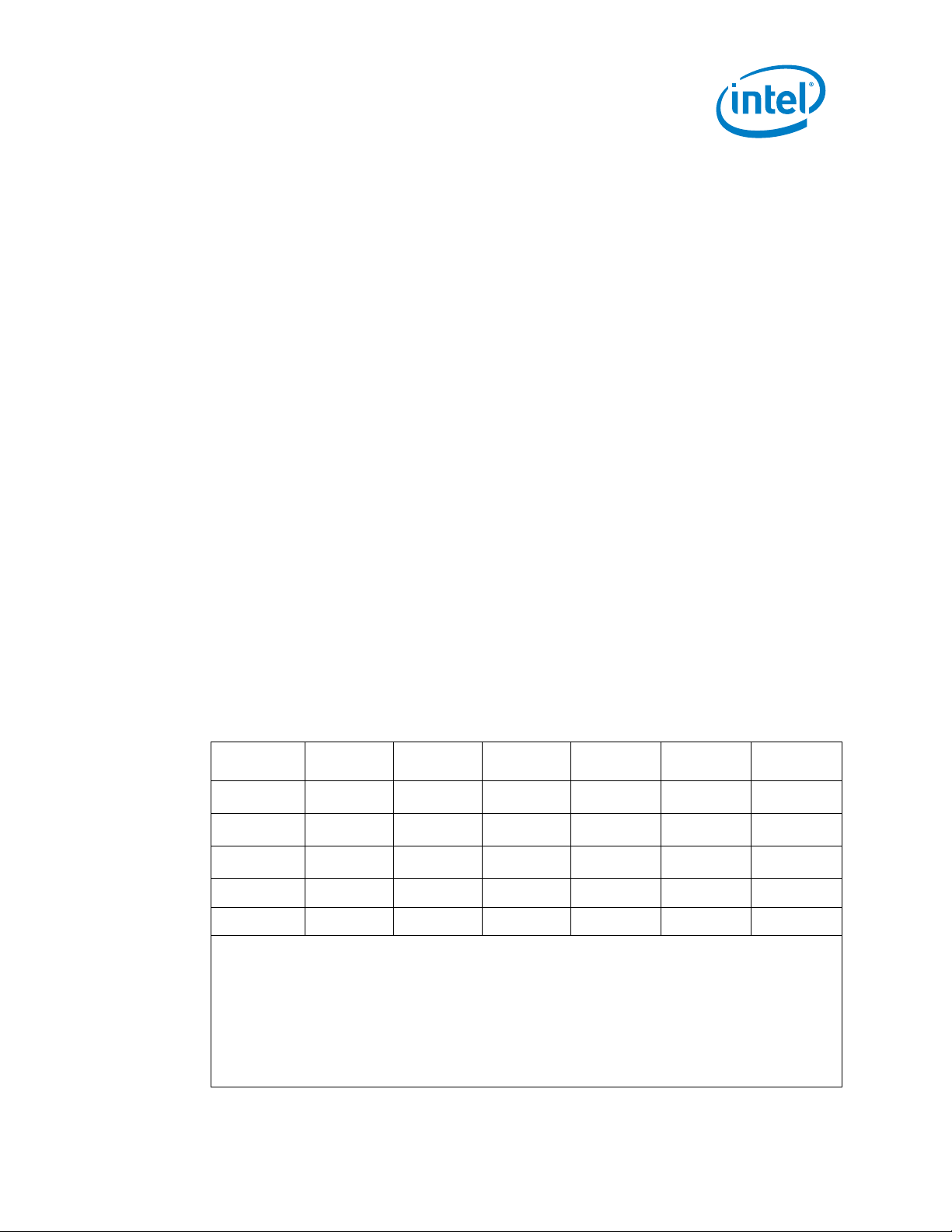
部件名称
(Parts)
铅
(Pb)
汞
(Hg)
镉
(Cd)
六价铬
(Cr(VI))
多溴联苯
(PBB)
多溴二苯醚
(PBDE)
主机板
Motherboard
×
○ ○ ○ ○ ○
机壳Chassis
×
○ ○ ○ ○ ○
缆线Cables
×
○ ○ ○ ○ ○
风扇 Fan
○ ○ ○ ○ ○
○
散热器Heat sink
○ ○ ○ ○ ○
○
本表格依据 SJ/T 11364 的规定编制。
○:表示该有害物质在该部件所有均质材料中的含量均在GB/T 26572标准规定的限量要求以下。
○:Indicates that this hazardous substance contained in all homogeneous materials of such component is within the limits specified in GB/T 26572.
×:表示该有害物质至少在该部件的某一均质材料中的含量超出GB/T 26572标准规定的限量要求。
×: Indicates that the content of such hazardous substance in at least a homogeneous material of such component exceeds the limits specified in
GB/T 26572.
对销售之日的所售产品,本表显示我公司供应链的电子信息产品可能包含这些物质。注意:在所售产品中可能会也可能不会含有所有所列的部件。
This table shows where these substances may be found in the supply chain of our electronic information products, as of the date of sale of the
enclosed product. Note that some of the component types listed above may or may not be a part of the enclosed product
1.3 Voluntary Control Council for Interference (VCCI) Warning
Class A ITE
この装置は、情報処理装置等電波障害自主規制協議会(VCCI)クラスA情報技術
装置です。この装置を家庭環境で使用すると電波妨害を引き起こすことがあります。こ
の場合には使用者が適切な対策を講ずるよう要求されることがあります。
1.4 Europe – EU Declaration of Conformity
Hereby, Intel Corporation declares that the radio equipment type RRS-H1000, RRSH3000 and RRS-H4000 is in compliance with…
• Radio Equipment Directive (RED) 2014/53/EU
• EU directive 2011/65/EU (RoHS II)
The full text of the EU declaration of conformity is available at the following internet
address:
1.4.1 Other Regulatory Requirements
Hereby, Intel Corporation declares that the radio equipment type RRS-H1000, RRSH3000 and RRS-H4000 is in compliance with…
• REACH Regulation (EC) 1907/2006
• WEEE Directive 2012/19/EU
China RoHS Declaration
Management Methods on Control of Pollution From Electronic Information Products
(China RoHS declaration)
产品中有害物质的名称及含量
Hazardous Substances Table
Intel® Responsive Retail Sensor (RRS) Hx Series Sensor
August 2018 User & Installation Guide
Revision 0.4 Page: 9
Page 10
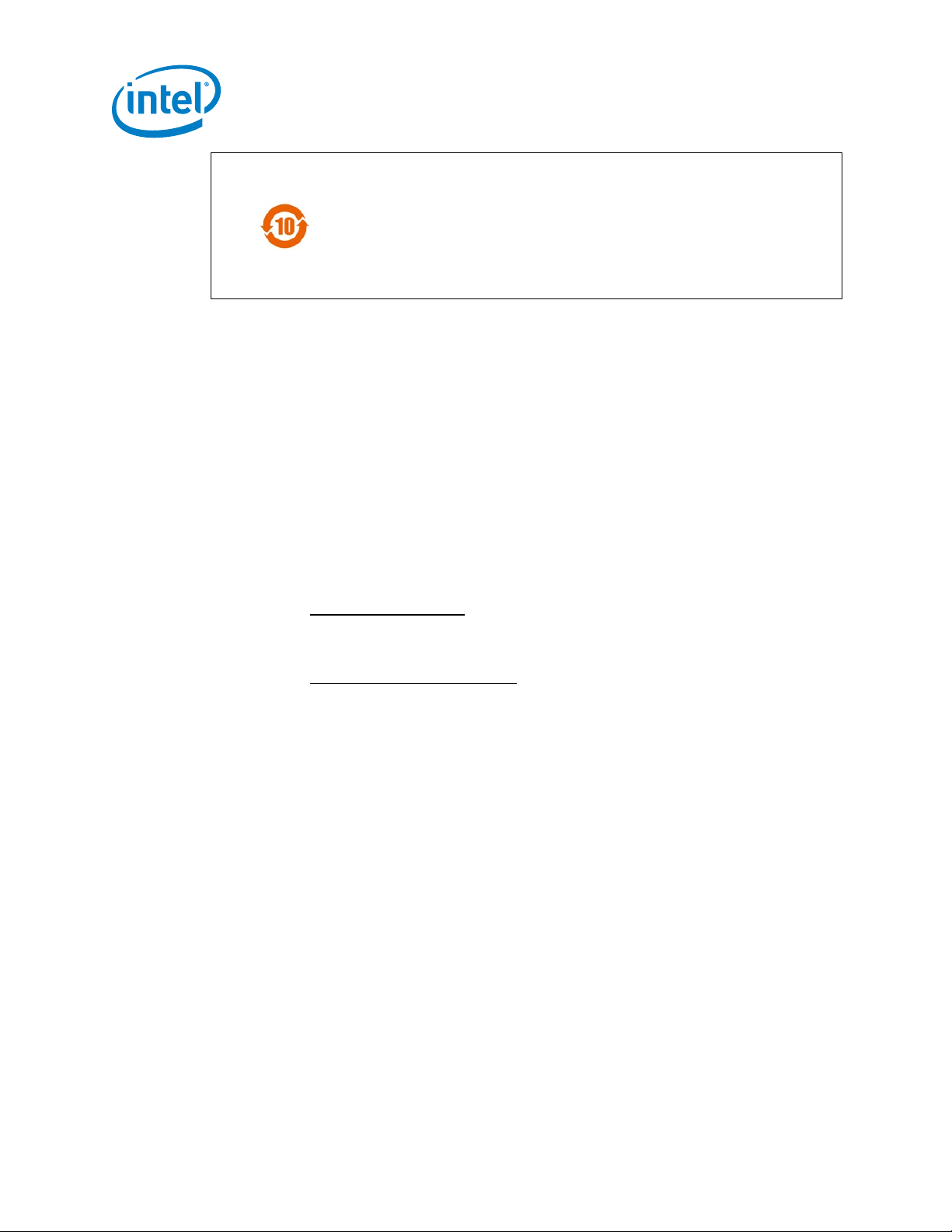
除非另外特别的标注,此标志为针对所涉及产品的环保使用期限标志.
某些可更换的零部件可能会有一个不同的环保使用期限(例如,电池单元模块).
此环保使用期限只适用于产品在产品手册中所规定的条件下工作.
The Environmental Protection Use Period (EPUP) for all enclosed products and their parts are per the symbol shown here, unless otherwise marked.
Certain field-replaceable parts may have a different EPUP (for example, battery modules) number. The Environment-Friendly Use Period is valid
only when the product is operated under the conditions defined in the product manual.
1.5 H1000 Specific Instruction & Warning
This device has been designed to operate with the antennas listed below, and having a
maximum gain of 8.5 dBi. Antennas not included in this list or having a gain greater than
8.5 dBi are strictly prohibited for use with this device. The required antenna impedance is
50 ohms.
Ce dispositif a été désigné pour fonctionner avec les antennes énumérées ci-dessous, et
ayant un gain maximum de 8.5 dBi. Les antennes non incluses dans cette liste ou ayant
un gain plus grand que 8.5 dBi sont strictement interdites pour l'utilisation avec cet
appareil. L'antenne requise impédance est 50 ohms.
(A) The recommended antenna types for the H1000 unit are listed below (and section
10.3.6.2):
a. Ceiling/Wall Mounting: Laird RFID Panel Antenna, S8655P (ETSI) or
S9025P (FCC). This antenna has a circularly polarized pattern and provide
5.5 dBi gain.
b. Tabletop Point-of-Sale (POS): Times-7 RFID Near-Field Antenna, A1030.
This antenna has a circularly polarized pattern and provides -15.0 dBi gain.
(B) The H1000 has 4x external ports, connector type Reverse Polarity SMA (SMA-R).
The maximum allowable torque for these external connectors is 10 in-lbs, max.
(C) It is possible that these port connectors require an RF adapter depending upon the
actual antenna that is used and it’s mating connector type.
Intel® Responsive Retail Sensor (RRS) Hx Series Sensor
User & Installation Guide August 2018
Page: 10 Revision 0.4
Page 11
2.0 Safety and Regulatory Information
2.1.1 Safety & Regulatory Warnings
USERS: This device is intended to be use/operated by Instructed Persons &
Skilled Persons only.
Do Not Open: This device is not intended to be open by the operator. There
are no user serviceable parts.
Installation and Maintenance: Do not connect/disconnect any cables to or perform
installation/maintenance on this device during an electrical storm.
This equipment is only to be connected to PoE networks without routing to outside plants.
This unit is supplied by an UL Listed I.T.E.
Intel® Responsive Retail Sensor (RRS) Hx Series Sensor
August 2018 User & Installation Guide
Revision 0.4 Page: 11
Page 12
3.0 Product Description
H4000
H3000
H1000
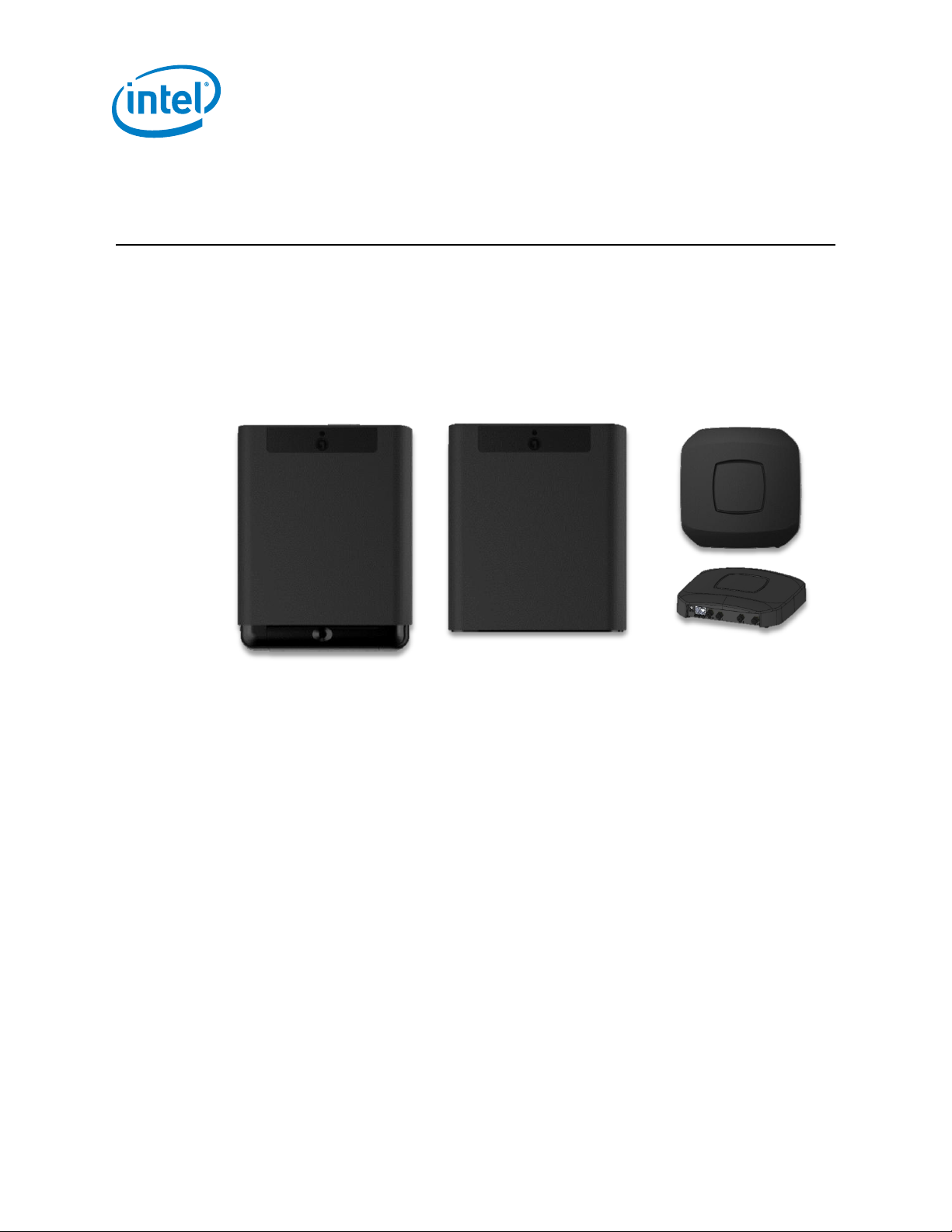
The RRS-H1000 (Model: H1000), RRS-H3000 (Model: H3000) and RRS-H4000 (Model:
H4000) are members of the “Smart Sensor” family that is part of the Intel© Responsive
Retail System (RRS). These devices have capabilities for several on-board sensors
including an EPC Gen 2 UHF RFID Interrogator (reader). These sensors are designed to
work stand-alone, or in a network of other “Smart Sensors” as part of an Internet-ofThings (IoT) system where computing power is pushed out to the edge devices.
Figure 1: Responsive Retail Sensor Hx000 Family
Intel® Responsive Retail Sensor (RRS) Hx Series Sensor
User & Installation Guide August 2018
Page: 12 Revision 0.4
Page 13
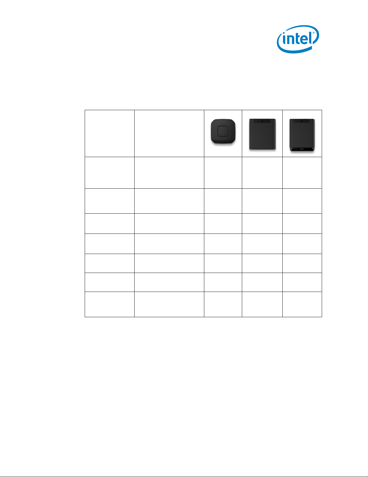
Feature
Description &
Purpose
H1000
H3000
H4000
Reader
UHF EPC Gen 2 RFID
Reader module. This
module supports the core
functionality of RRS (i.e.
inventory management)
Antenna
7.67 dBi Slot Coupled
Microstrip Antenna
.
*
Red Detector
Detect human motion
Magnetometer
Reading the orientation of
the device as it is
mounted.
Omnivision OV5640 5MP
camera for video and still
image capture
Redpine Systems
RS9113 integrated WiFi/BLE
Humidity
Read the temperature
and humidity of the
environment where the
device is mounted.
3.1 Features
The H3000 and H4000 are designed to be ceiling or wall mounted facing into the retail
space and hidden from view. H1000 is designed to be mounted under a table or flush
mounted to a wall or cabinet and hidden from view. The following features are unique to
the three different models
Intel® Responsive Retail Sensor (RRS) Hx Series Sensor
August 2018 User & Installation Guide
Revision 0.4 Page: 13
*
The H1000 model is designed to support up to four reverse-SMA RF ports for
connecting up to four UHF RFID external antennas (not included) on the front panel.
Page 14

3.2 Block Diagrams
3.2.1 Top Level
A block diagram of the PCBA common to all products is shown below.
Figure 2: Hx000 Functional Block Diagram
Intel® Responsive Retail Sensor (RRS) Hx Series Sensor
User & Installation Guide August 2018
Page: 14 Revision 0.4
Page 15

3.2.2 RF Subsystem
The R2000 subsystem (aka “RF Circuitry”) is defined as the ARM M4 (aka
Microcontroller), R2000/RFID transceiver (aka “Indy Reader Chip”), power amplifier,
directional coupler, 4-port antenna switch and associated matching components. The
Sensors uses an internal dual linear antenna that only requires two of the four ports. The
H1000 brings out all four of the antenna ports to external R-SMA connectors allowing the
System Integrator to use antennas that are not collocated with the H1000reader. Below
is a block diagram of the R2000 Sub-System.
3.2.3 R2000 ASIC
For reference, a block diagram of the Impinj R2000 ASIC internal components is shown
below.
Figure 3: R2000 ASIC Block Diagram
Intel® Responsive Retail Sensor (RRS) Hx Series Sensor
August 2018 User & Installation Guide
Revision 0.4 Page: 15
Page 16

4.0 System Description
The RRS-Hx Sensor is just one component of the larger Intel® Responsive Retail
Platform (RRP) shown in Figure 3.1 below. The system is comprised of one or more
Retail Sensors and a RRP appliance for control and orchestration. Customers may
integrate their own cloud infrastructure component for data storage and analytics.
The power of the RRP is in the networked communication and coordination that exists
between the RRS’s themselves and between the RRS and the RRP device. Whether a
system deployment has 5 or 500 Retail Sensor Platforms, this communication and
coordination greatly simplifies initial configuration as well as the operational management.
4.1 Data Flow
From a data flow perspective, RFID reader interrogates the tag population within its field
of view and passes information regarding the tags as well as information from other
various on-board sensors to the RRP appliance. The RRP appliance does more than just
aggregate the data from the sensor population, it also orchestrates the behavior of each
sensor to optimize the overall in-store data collection process. Inventory Events, Alerts
and System Status can be forwarded from the RRP device to applications running in the
customer’s cloud infrastructure. Figure 9 illustrates the flow of data and control within the
RRS.
Figure 4: RRS Functional Block Diagram
Intel® Responsive Retail Sensor (RRS) Hx Series Sensor
User & Installation Guide August 2018
Page: 16 Revision 0.4
Page 17

Figure 5: System Data Flow
4.2 Customer Cloud Applications
Customers may utilize their own cloud infrastructure to process the data. RRP will
provide a set of REST interfaces for customer applications to obtain the data necessary
to determine item identification, location, movement and status.
4.3 Responsive Retail Platform (RRP)
The Responsive Retail Platform (RRP) performs sensor control, sensor management,
sensor data aggregation, data processing, event generation and event management. It
supports configuration and management from a local interface.
4.4 RFID Readers
The RRS-Sensor devices provide the ability to remote command, control, status, and
data collection via Ethernet. Data from RFID tag reads as well as data from other onboard sensors is published to an MQTT broker. The data API is based on JSON RPC
commands, responses and indications. JSON-RPC is a text based, stateless, lightweight
remote procedure call (RPC) protocol.
Intel® Responsive Retail Sensor (RRS) Hx Series Sensor
August 2018 User & Installation Guide
Revision 0.4 Page: 17
Page 18

4.5 RRP Device to Sensor Protocol
The RRS Sensor provides a remote capability for command, control, status and data
collection via JSON Remote Procedure Call (RPC) over MQTT. The Retail Gateway
Command set follows the JSON RPC 2.0 specification. JSON-RPC is a stateless,
lightweight protocol that is transport agnostic.
4.5.1 Request Object
The Request object has the following members:
jsonrpc
o A String specifying the version of the JSON-RPC protocol.
method
o A String containing the name of the method to be invoked.
params
o A Structured value that holds the parameter values to be used duringthe
invocation of the method.
o This member may be omitted.
id
o An identifier containing a String or Number value (if included).
o This member is used to correlate the context between the two objects.
4.5.2 Notification Object
A Notification is a Request object without an "id" member. A Request object that is a
Notification signifies that a corresponding Response object is not expected.
Intel® Responsive Retail Sensor (RRS) Hx Series Sensor
User & Installation Guide August 2018
Page: 18 Revision 0.4
Page 19
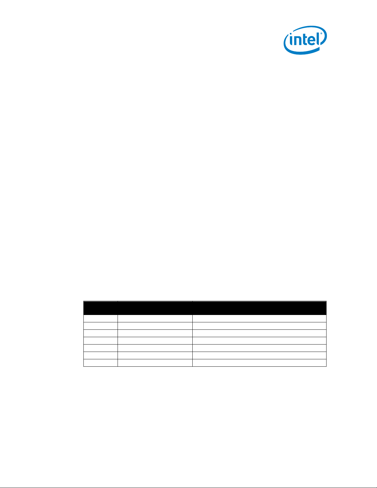
Code
Message
Meaning
-32001
Wrong State
Cannot be executed in the current state
-32002
Function not supported
The requested functionality is not supported
-32100
No facility assigned
The RRS has no Facility ID assigned yet
-32601
Method not found
The method does not exist
-32602
Invalid Parameter
Out of range or invalid format
-32603
Internal Error
RFID Sensor Platform application error
-32700
Parse error
Invalid JSON Object
4.5.3 Response Object
The Response is expressed as a single JSON Object, with the following members:
jsonrpc
o A String specifying the version of the JSON-RPC protocol.
result
o The presence of this member indicates successful execution of the
corresponding method.
o This member is not present when the execution of the method resulted in an
error.
error
o The presence of this member indicates unsuccessful execution of the
corresponding method.
o This member is not present when the execution of the method was successful.
o When present, the error Object contains the following members:
code
o An integer that indicates the error type that occurred.
message
o A String providing a short description of the error.
data
o A Primitive or Structured value that contains additional formation
o See table below for supported error codes.
id
o This member is always present on a response and contains the same value as
the id member in the corresponding Request Object.
o This member is not present on indications.
about the error (optional).
4.5.4 Error Codes
The RFID Sensor Platform provides one of the following error codes when an error
occurs.
4.5.5
Intel® Responsive Retail Sensor (RRS) Hx Series Sensor
August 2018 User & Installation Guide
Revision 0.4 Page: 19
Page 20

4.5.6 Commands/Responses/Indications
Commands
Brief Description
connect
Request connect credentials from the GW
get_state
Retrieve the capabilities and current configuration
set_frequency_plan
Set the Region of Operation frequency plan
set_antenna_config
Configure the per antenna port parameters
set_select
Define a set of tag select criteria
set_post_match
Define the post singulation match criteria
apply_behavior
Applies a set of RFID parameters and…
start_inventory
Command a single or multiple inventory round(s)
stop_inventory
Stop the inventory round in progress.
tag_read_memory
Read up to 32 16-bit words from the tag memory
tag_write_memory
Write up to32 16-bit words to the tag memory
get_tag_database
Retrieve the Tag Database from the RRS
get_bist_results
Query the Built-In-Self-Test (BIST) data of the RRS
set_device_alert
Configures and/or acknowledges device alerts
set_alert_threshold
Configure a particular “device_alert" threshold
ack_alert
Acknowledge a particular “device_alert"
set_motion_event
Configure the “motion_event" thresholds
get_sw_version
Retrieve the software versions of the RRS
load_defaults
Command to load the power-on default settings
capture_image
Capture an image using the on-board camera
start_video
Start streaming video using the on-board camera
stop_video
Stop streaming video using the on-board camera
set_led
Control the RFID Sensor Platform LED
reset
Perform a soft reset of the Embedded RFID module
reboot
Perform a reboot of the entire sensor platform
shutdown
Perform a clean shutdown of the entire sensor
set_facility_id
Set the Facility ID string assigned to this sensor
set_dense_reader_mode
Command the use of “Dense Reader Mode”
Indications
Brief Description
device_alert
Indicates a Built-In-Test event has occurred
heartbeat
Indicates the RRS is still operational
motion_event
Indicates the detection of motion from the IR sensor
status_update
Indicates a change in status
inventory_data
Indicates the receipt of RFID tag information
inventory_complete
Indicates that the inventory round is complete
inventory_event
Indicates that an inventory "event" has occurred
Intel® Responsive Retail Sensor (RRS) Hx Series Sensor
User & Installation Guide August 2018
Page: 20 Revision 0.4
Page 21

Model
H1000
H3000
H4000
Electrical:
Air Interface Protocol
EPC UHF RFID Class 1 Gen 2 (ISO
18000-6C)
EPC UHF RFID Class 1 Gen 2 (ISO
18000-6C)
EPC UHF RFID Class 1 Gen 2 (ISO
18000-6C)
Operating Frequency
902-928 MHz (US), 865-868 MHz (ETSI)
902-928 MHz (US), 865-868 MHz (ETSI)
902-928 MHz (US), 865-868 MHz (ETSI)
Radiated Power
N/A
Up to 4W EIRP (2W ERP)
Up to 4W EIRP (2W ERP)
Antenna
N/A
Integrated 6 dBi Dual-Linear Polarized
Integrated 6 dBi Dual-Linear Polarized
Power Output
Up to +27.03 dBm
Up to +28.15 dBm
Up to +28.16 dBm
Power Source
PoE+ (IEEE 802.3af, 802.3at, Cisco
UPOE)
PoE+ (IEEE 802.3af, 802.3at, Cisco
UPOE)
PoE+ (IEEE 802.3af, 802.3at, Cisco
UPOE)
Power Consumption
16W max, 5W max idle
16W max, 5W max idle
13W max, 5W max idle
Tag Read Range
Based on external antenna type
>15m
>15m
Tag Read Rate
>600 tag reads/sec
>600 tag reads/sec
>600 tag reads/sec
Visual Indicators
Single tri-color LED
Single tri-color LED
Single tri-color LED
IR Detection
N/A
Panasonic PIR Sensor
Panasonic PIR Sensor
Video Camera
N/A
N/A
5MP, FOV-D 110˚, H.264 or raw video,
module rotation 0˚ to 90˚
Antenna Ports
4-Ports, Reverse SMA
N/A
N/A
Mechanical:
Dimensions
6.25" x 6.25" x 1.25” (15.9cm x 15.9cm
x 3.2cm)
10.4" x 9" x 2” (26.4cm x 22.9cm x
5.1cm)
12" x 9" x 2” (30.5cm x 22.9cm x
5.1cm)
Weight
1.46 lbs. (0.66 kg)
4.00 lbs. (1.82 kg)
4.35 lbs. (1.98 kg)
Mounting
Custom mounting plate, or desk top
VESA 75mm pattern, M4 threads
VESA 75mm pattern, M4 threads
Color
Black
Black or White
Black or White
Environmental:
Operating Temperature
0°C to +35°C
0°C to +35°C
0°C to +35°C
Rating
IP-50
IP-50
IP-50
Application Interface:
Network Connectivity
Ethernet 10/100
Ethernet 10/100
Ethernet 10/100
IP Address Configuration
DHCP or static
DHCP or static
DHCP or static
Data Protocol
JSON-RPC 2.0 over MQTT
JSON-RPC 2.0 over MQTT
JSON-RPC 2.0 over MQTT
Configuration/Management
mDNS/DNS-SD
mDNS/DNS-SD
mDNS/DNS-SD
Time Synchronization
Network Time Protocol (NTP)
Network Time Protocol (NTP)
Network Time Protocol (NTP)
Software/Firmware Update
Remotely upgradable
Remotely upgradable
Remotely upgradable
Sensor Provisioning Function
Near Field Communications (NFC), no
power required
Near Field Communications (NFC), no
power required
Near Field Communications (NFC), no
power required
4x External Antenna Ports
For use with customer supplied
external antenna, up to 4x
simultaneously. 4-Ports, Reverse SMA
N/A
N/A
Regulatory:
Safety Compliance
IEC 60950-1
IEC 60950-1
IEC 60950-1
Radio Approvals
1
FCC, ETSI, PRC (China), Singapore,
Japan, among others
1
FCC, ETSI, PRC (China), Singapore,
Japan, among others
1
FCC, ETSI, PRC (China), Singapore,
Japan, among others
5.0 Product Specifications
Intel® Responsive Retail Sensor (RRS) Hx Series Sensor
August 2018 User & Installation Guide
Revision 0.4 Page: 21
Page 22

6.0 Hardware Description
D1
M1
C1
J1
VESA
75 mm
6.1 H4000 and H3000 Models
Figure 6 highlights the external interfaces.
Figure 6: H400/H3000 Front and Back interfaces
6.1.1 Mounting Holes
The RRS-H3000(Model: H3000) and RRS-H4000(Model: H4000) sensors provides a 75mm hole pattern compatible with several types of mounting brackets. The holes are
threaded to accept up to a 1 cm M4 stud.
6.1.2 Motion Sensor M1
The RRS-H3000(Model: H3000) and RRS-H4000(Model: H4000) sensors uses a passive
infrared sensor to detect human motion in the field of the RFID antenna.
6.1.3 Connector J1 (RJ-45)
The RRS-H3000 and RRS-H4000 sensor is a 48V Power Over Ethernet (POE) Class 3
device as defined in IEEE 802.3af. The sensors supports 10/100 Ethernet on this same
connector.
6.1.4 Camera (C1)
The RRS-H4000 uses an Omnivision 5MP camera with a 100 degree horizontal field of
view. The H4000 microprocessor is capable of streaming 1080p video at 30 frames per
second. The camera module offers a rotation range of 0˚ to 90˚.
Intel® Responsive Retail Sensor (RRS) Hx Series Sensor
User & Installation Guide August 2018
Page: 22 Revision 0.4
Page 23
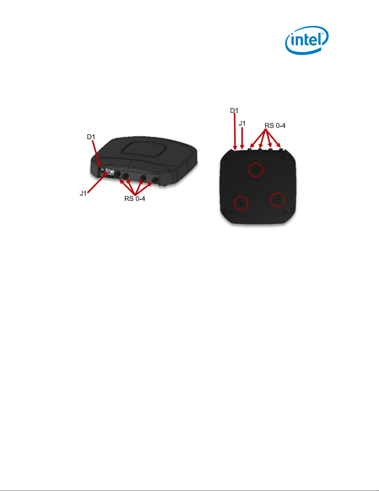
6.2 H1000 Model
Figure 7 highlights the external interfaces.
Figure 7:
RRS-H1000
6.2.1 Mounting
6.2.2 Connector J1 (RJ-45)
The RRS-H1000 is a 48V Power Over Ethernet (POE) Class 3 device as defined in IEEE
802.3af. The RRS-H1000 supports 10/100 Ethernet on this same connector.
6.2.3 Reverse-SMA Connectors RS 0-4
The RRS-H1000 provides four Reverse-SMA RF ports for connecting up to four UHF
RFID external antennas (not included).
6.3 Visual Indicator D1 (Tri-Color LED) for all models
The RRS-Sensors provides a multicolored visual indicator to notify the user of the
following operational states.
6.3.1 OFF
An LED state of “off" indicates the RRS-Sensors has either been commanded to disable
its visual indicator or is otherwise non-operational.
Intel® Responsive Retail Sensor (RRS) Hx Series Sensor
August 2018 User & Installation Guide
Revision 0.4 Page: 23
Page 24

6.3.2 GREEN (Power On)
An LED state of "solid green" is the default to indicate power has been successfully
applied to the RRS. This initial LED state should not last longer than 2 – 3 minutes.
After 2 – 3 minutes, the LED color should transition to indicate successful OS boot.
6.3.3 Light BLUE
An LED state of “solid light blue" indicates the RRS-Sensors has successfully booted to
the Linux OS, but the RFID Applications are not yet running.
6.3.4 Flashing WHITE
An LED state of “flashing white" after boot up indicates the RRS-Sensors is in the
process of discovering the RFID Gateway. The state of “flashing white" can also be
commanded (i.e. Beacon Mode) by the Gateway via JavaScript Object Notation (JSON)
Remote Procedure Call (RPC) for visually identifying the RRS.
6.3.5 Solid PURPLE
An LED state of “solid purple" indicates the RRS-Sensors is waiting to read a security
provisioning tag.
6.3.6 Flashing PURPLE
After a security provisioning tag has been successfully read, the RRS-Sensors LED state
will be “flashing purple" for a period of 5 seconds.
6.3.7 Solid Yellow (Idle)
Following Gateway Discovery, an LED state of “solid yellow" indicates that The RRSSensors is in the idle state and ready to accept commands.
6.3.8 BLUE
An LED state of “solid blue" indicates the RRS-Sensors is currently in an Inventory Cycle
(i.e. transmitting) but not receiving any tag data.
6.3.9 Flashing BLUE
An LED state of “flashing blue" indicates the RRS-Sensors is currently in an Inventory
Cycle (i.e. transmitting) and successfully communicating with RFID tags.
6.3.10 Flashing RED
An LED state of “flashing red" indicates the RRS-Sensors has detected a failure. This
will continue until the alert is acknowledged by the RFID Gateway or the CLI.
Intel® Responsive Retail Sensor (RRS) Hx Series Sensor
User & Installation Guide August 2018
Page: 24 Revision 0.4
Page 25

7.0 Software Description
Figure 8: RRS-Hx000 Software Stack
7.1 Operating System
The H4000/H3000 uses the Freescale I.MX6 processor running a Yocto Project Linux
kernel and file system.
7.2 Secure Platform
The H4000/H3000 incorporates both secure boot, file system encryption and software
packages that are signed by Intel’s EDSS to insure that only the software intended for
this device is allowed to run.
7.3 Security Provisioning
The H4000/H3000 includes an embedded NFC tag for programming the security
information required to join the Responsive Retail Platform. An Android Application is
available to easily program this information into the sensor. The screenshots below
show how to use this application to program the H4000/H3000. TODO Add screenshots
here)
Intel® Responsive Retail Sensor (RRS) Hx Series Sensor
August 2018 User & Installation Guide
Revision 0.4 Page: 25
Page 26

8.0 Theory of Operation
The power of RRS is in the networked communication and coordination that exists
between the Sensor Platforms themselves and between the RFID Gateway. Whether a
particular RFID system deployment has 5 or 500 RRS devices, this communication and
coordination greatly simplifies initial configuration as well as the operational management.
This section defines the set of messages used between the RFID Retail Sensor Platform
and the RFID Gateway that facilitates this orchestration.
Some of these messages affect the RF power output and modulation scheme being
transmitted. The Impinj R2000 RF subsystem buffers all commands received from the
RFID Gateway via the Host Processor. NOTE: Any command that attempts to set a
parameter to a value that is outside its valid range or would otherwise cause the RRSSensors to no longer be compliant with its certification will return an error code and the
previous command settings will persist.
Several Use Cases have been defined that illustrate initial discovery, configuration and
tag population management. Detailed message definitions can be found in the Retail
Sensor Platform API.
Intel® Responsive Retail Sensor (RRS) Hx Series Sensor
User & Installation Guide August 2018
Page: 26 Revision 0.4
Page 27

CloudGatewaySensor
Developer
SI
NFC Provisi oning of Token/Has h
ntpdate <Ti me Server>
time sync
{:Root CA URL ,
:Time Ser ver }
REST <Root CA URL>
Root CA
{:Root CA}
Authentica te against Hash
REST (https ://rfid-gw/creds) inc lude Token
MQTT Crede ntials w/Public Key L ist
REST (http: //rfid-gw/urls)
URL List
Authenticate using Root CA
REST (https ) validate Token
VALID
Set MQTT pas sword file
Reload MQT T configuration
Connect to M QTT Broker using C redentials
SUCCESS
MQTT
RPC Comm and (connect request)
RPC Command (connect response)
RPC Indication (status ready)
8.1 RFID Gateway Discovery
A goal of the RFID Sensor Platform is to be as much of a “zero-conf" installation as
possible. Once power is applied, the RRS Sensor autonomously acquires a network
address via DHCP and discover the RRS Gateway. The RRS Sensor also supports
encryption via a TLS connection to the MQTT broker. An optional “provisioning tag”
containing a hash and token can be used for the RRS Sensor to authenticate the Cloud
and the RRS Gateway to authenticate the sensor as it connects. Figure 9 illustrates the
message exchange involved in this use case.
Intel® Responsive Retail Sensor (RRS) Hx Series Sensor
August 2018 User & Installation Guide
Revision 0.4 Page: 27
Figure 9: Device Discovery
Page 28

8.2 RFID Behavior Control
Parameter
Definition
action
Specifies the action to be taken.
The valid values are “START" and “STOP".
action_time
Specifies the millisecond epoch time to apply the behavior. If
zero or not included, the behavior is applied immediately.
behavior
Optional set of behavior parameters (see below).
id
The ID string assigned to this behavior
operation_mode
The embedded RFID module transmit operation mode.
The valid values are "Continuous" and "NonContinuous".
The default value is "NonContinuous".
link_profile
The RF Link Profile to be used for this behavior.
(see 錯誤! 找不到參照來源。)
The valid range is 0 – 4.
power_level
The power output level in dBm to be used for this behavior.
The valid range is 0 – 27.03.
dwell_time
The maximum amount of time (ms) spent on a particular virtual
port before switching to the next virtual port during an inventory
cycle. If this parameter is zero, the “inv_cycles" parameter may
not be zero.
The valid range is 0 – 65535.
inv_cycles
The maximum amount of inventory cycles to attempt on a
particular virtual port before switching to the next virtual port
during an inventory cycle. If this parameter is zero, the
“dwell_time" parameter may not be zero.
The valid range is 0 – 65535.
selected_state
Specifies the state of the “SL" flag to be used for this behavior
when specifying a select protocol operation. The valid values
are:
“Any", “Deasserted" and “Asserted".
session_flag
Specifies which inventory session flag is matched against the
state specified by “target_state". (see 錯誤! 找不到參照來源。)
The valid values are “S0", “S1", “S2" and “S3".
target_state
Specifies the state of the inventory session flag specified by
“session_flag" that are to apply the subsequent tag protocol
operation. (see 錯誤! 找不到參照來源。)
The valid values are “A" and “B".
q_algorithm
The specific Q algorithm being configured.
The valid values are “Fixed" and “Dynamic". When using a
“Fixed" algorithm, the number of time slots is 2^Q. When using
a “Dynamic" algorithm, the Smart Sensor Platform’s embedded
module will vary the number of slots dynamically based on the
number of tags responding.
fixed_q_value
The fixed Q value to use (valid when q_algorithm = Fixed).
The valid range of this parameter is 0 – 15.
repeat_until_no_tags
Specifies whether or not the singulation algorithm should
In addition to using default values, the RFID Sensor Platform supports the detailed RFID
configuration via the “apply_behavior” API command. This command is shown below
(see the RFID API Command Set document for a complete set of command definitions).
Intel® Responsive Retail Sensor (RRS) Hx Series Sensor
User & Installation Guide August 2018
Page: 28 Revision 0.4
Page 29

continue until no more tags are singulated.
The valid values are “true" or “false".
start_q_value
The initial Q value to use at the beginning of an inventory round
(valid when q_algorithm = Dynamic).
The valid range of this parameter is 0 – 15.
min_q_value
The minimum Q value that would ever be used during an
inventory round (valid when q_algorithm = Dynamic).
The valid range of this parameter is 0 – 15.
max_q_value
The maximum Q value that would ever be used during an
inventory round (valid when q_algorithm = Dynamic).
The valid range of this parameter is 0 – 15.
threshold_multiplier
A 4X multiplier applied to the Q-adjustment threshold as part of
the dynamic-Q algorithm.
The valid range of this parameter is 0 – 255.
retry_count
The number of times to try another execution of the singulation
algorithm before either toggling the target flag or terminating
the operation.
The valid range of this parameter is 0 – 255.
toggle_target_flag
Specifies whether or not to toggle the targeted flag.
The valid values are “true" or “false".
toggle_mode
When toggle_target_flag is true, this value specifies when to
toggle the targeted flag. The valid values are “None”,
“OnInvCycle", OnInvRound”, or “OnReadRate".
perform_select
Specifies whether or not to perform a select command based
on the previously configured criteria
The valid values are “true" and “false".
perform_post_match
Specifies whether or not to perform a post singulation match
based on the previously configured criteria.
The valid values are “true" and “false".
filter_duplicates
Specifies whether or not the RFID Sensor Platform should filter
out duplicate tag information before sending to the Gateway.
The valid values are “true" or “false".
auto_repeat
Specifies whether or not to continue performing inventory
rounds until the “stop_inventory" command is received.
When this value is "No", an "inventory_complete" indication will
be sent from the RFID Sensor Platform to the RRS Gateway at
the end of the inventory round.
The valid values are “true" and “false".
delay_time
The amount of time (ms) that the transmitter is turned off
between subsequent inventory rounds. Used when
"auto_repeat" is true to control the transmit duty cycle.
The valid range is 0 – 65535.
Parameter / Profile Index
0 1 2 3 4
Modulation Type
DSB-
ASK
PR-ASK
PR-ASK
DSB-
ASK
DSB-
ASK
Tari Duration (us)
25
25
25
6.25
6.25
Data 0/1 Difference
1
0.5
0.5
0.5
0.5
Pulse Width (us)
12.5
12.5
12.5
3.13
3.13
R-T Calculation (us)
75
62.5
62.5
15.63
15.63
Intel® Responsive Retail Sensor (RRS) Hx Series Sensor
August 2018 User & Installation Guide
Revision 0.4 Page: 29
Page 30

T-R Calculation (us)
200
85.33
71.11
20
33.33
Divide Ratio
8
21.33
21.33
8
21.33
Data Encoding
FM0
Miller-4
Miller-4
FM0
FM0
Pilot Tone
1 1 1 1 1
Link Frequency (kHz)
40
250
300
400
640
Data Rate (kbps)
40
62.5
75
400
640
Session
Tag Energized
Tag Not Energized
S0
Indefinite
None
S1
500 ms < persistence < 5 s
2 s < persistence
S2
Indefinite
2 s < persistence
S3
Indefinite
2 s < persistence
8.3 Managing Large Tag Populations
The RFID Gateway can segregate a large tag population into several smaller ones using
the Retail Sensor Platform’s “select" and “post-match" functions. Segregation allows the
RRS-Sensors to more accurately inventory a tag population by avoiding collisions. This
same functionality can also be used to isolate a single tag that might be located in a
challenging RF environment or perhaps physically oriented in a less than optimal fashion.
A challenge in managing larger tag populations is dealing with “tag collisions" during the
query-response (more than one tag responding at exactly the same time). The RRS-
Sensors offers an adaptive algorithm (Dynamic-Q) function to mitigate tag collisions. An
adaptive Q algorithm increases the reading efficiency significantly thereby reducing the
time it takes to completely inventory a large tag population. The RRS-Sensors allows the
RFID Gateway to optimally configure the Q Algorithm based on a known tag population.
Dynamic-Q is used by default, which relieves the Gateway from having to explicitly set
the Q-value.
Intel® Responsive Retail Sensor (RRS) Hx Series Sensor
User & Installation Guide August 2018
Page: 30 Revision 0.4
Page 31

8.3.1 Normal Scan (Single Target)
This Use-Case illustrates the most common situation where a number of tagged items
are being continuously inventoried on an RFID-enabled “smart shelf" or perhaps an
overhead Retail Sensor Platform in an RFID-enabled “smart store". This mode will allow
multiple reads per tag for a moderate update of tag status to alert the RFID system
should a tagged item be moved. No tag filtering is specified. The figure below illustrates
the message exchange involved in this use case.
Figure 10 Normal Scan (Single Target) Data Flow
Intel® Responsive Retail Sensor (RRS) Hx Series Sensor
August 2018 User & Installation Guide
Revision 0.4 Page: 31
Page 32

8.3.2 Normal Scan (Dual Target)
This Use-Case illustrates the most common situation where a number of tagged items
are being continuously inventoried on an RFID-enabled “smart shelf" or perhaps an
overhead Retail Sensor Platform in an RFID-enabled “smart store". This mode will allow
multiple reads per tag for a moderate update of tag status to alert the RFID system
should a tagged item be moved. No tag filtering is specified. The figure below illustrates
the message exchange involved in this use case.
Figure 11 Normal Scan (Dual Target) Data Flow
Intel® Responsive Retail Sensor (RRS) Hx Series Sensor
User & Installation Guide August 2018
Page: 32 Revision 0.4
Page 33

8.3.3 High Mobility (Dual Target)
This Use-Case addresses the situation where a number of tagged items are being
continuously inventoried, and higher numbers of reads per tag are required to detect tag
mobility. Figure 4 illustrates the message exchange involved in this use case.
Figure 12 High Mobility Data Flow
Intel® Responsive Retail Sensor (RRS) Hx Series Sensor
August 2018 User & Installation Guide
Revision 0.4 Page: 33
Page 34

8.3.4 Deep Scan (Single Target)
This Use-Case illustrates a thorough “Deep Scan" using the most robust RF link to insure
that all tags within the coverage area are successfully read at least once. This mode
also uses suppression to allow weaker tags to respond without competing with the
multiple responses of other tags and is recommended only in situations where multiple
reads per tag is not required. Sessions 2 and 3 are used to provide longer suppression
times while scanning. Alternating between sessions 2 and 3 (and between A and B)
allows for a rapid recovery when rescanning the tag population. This use-case insures
that even the most distant tags with the weakest backscatter signal can be eventually
read. Figure 6 illustrates the message exchange involved in this use case.
Figure 13 Deep Scan Data Flow
Intel® Responsive Retail Sensor (RRS) Hx Series Sensor
User & Installation Guide August 2018
Page: 34 Revision 0.4
Page 35

8.3.5 Searching for a Single Tag or Group of Tags
There are two ways to search for an individual tag or group of tags using The RRSSensors.
The “select" function configures the RRS-Sensors with set of tag filter criteria and
instructs those tags that match that filter criteria to modify a certain register flag, forcing it
to a known value prior to singulation. The tag protocol operation (i.e. read, write, kill) is
applied only to those tags that meet the filter criteria. When tag populations are relatively
large (> 1000) or when it is critical to apply a tag protocol operation to only a single tag,
this method of filtering is preferred. A good example of an applied use of the "select"
function would be at the point-of-sale (POS) where tags could be deactivated (killed)
prior to exiting a controlled area.
The "post-match" function configures The RRS-Sensors with set of tag filter criteria that
is applied "post" singulation or after a particular tag protocol operation is performed.
Even though the tag still has to compete in the RF environment of the singulation
process, the only data sent to the RFID Gateway is from those tags that match the filter
criteria defined in the "post match" function. “Post Match" filtering is a single step
process, tag memory is not modified and all tags respond to the inventory request.
When tag populations are relatively small (< 1000), this method of filtering on certain tags
is more efficient. A good example of an applied use of the "post match" function would
be when searching a larger tag population with a hand scanner for a particular tag or
group of tags.
Intel® Responsive Retail Sensor (RRS) Hx Series Sensor
August 2018 User & Installation Guide
Revision 0.4 Page: 35
Page 36

8.3.5.1 Tag "Select"
This Use-Case shows an example of the tag "select" function to search for a single tag or
group of tags. Figure 7 below illustrates the message exchange involved in this use case.
Figure 14 Tag Select Data Flow
Intel® Responsive Retail Sensor (RRS) Hx Series Sensor
User & Installation Guide August 2018
Page: 36 Revision 0.4
Page 37

8.3.5.2 “Post Match" Filtered Inventory
This Use-Case shows an example of the tag "post match" function to search for a single
tag or group of tags. Figure 8 illustrates the message exchange involved in this use case.
Figure 15 Post Match Data Flow
Intel® Responsive Retail Sensor (RRS) Hx Series Sensor
August 2018 User & Installation Guide
Revision 0.4 Page: 37
Page 38

9.0 System Installation
9.1 RF Exposure Statement
Caution: The radiated output power of this device is below the FCC and
International radio frequency exposure limits. To avoid the possibility of exceeding
these exposure limits, always maintain a minimum distance of 34 cm (minimum
distance of model H1000 is 26 cm) between the antenna and the human body.
Details regarding the authorized configurations can be found at
http://www.fcc.gov/oet/ea/ by entering the FCC ID from the device.
Caution: L'antenne (s) utilisée (s) pour cet émetteur doit être installée pour assurer
une distance de séparation d'au moins 34 cm (la distance minimale du modèle
H1000 est de 26 cm) de Personnes et ne doivent pas être co-situés ou fonctionner
conjointement avec une autre antenne ou émetteur. Utilisateurs et Les installateurs
doivent être munis d'instructions d'installation d'antenne et de conditions
d'exploitation de l'émetteur pour Conformité à l'exposition RF.
9.2 Information to the User
§15.105 Information to the user
Note: This equipment has been tested and found to comply with the limits for a Class A digital
device, pursuant to part 15 of the FCC Rules. These limits are designed to provide reasonable
protection against harmful interference in a residential installation. This equipment generates, uses
and can radiate radio frequency energy and, if not installed and used in accordance with the
instructions, may cause harmful interference to radio communications. However, there is no
guarantee that interference will not occur in a particular installation. If this equipment does cause
harmful interference to radio or television reception, which can be determined by turning the
equipment off and on, the user is encouraged to try to correct the interference by one or more of
the following measures:
Reorient or relocate the receiving antenna.
Increase the separation between the equipment and receiver.
Connect the equipment to another POE source.
Consult the system integrator or authorized technician for help.
This Class A digital apparatus complies with Canadian ICES-003.
Cet appareil numérique de la classe B est conforme à la norme NMB-003 du Canada.
Intel® Responsive Retail Sensor (RRS) Hx Series Sensor
User & Installation Guide August 2018
Page: 38 Revision 0.4
Page 39

9.3 Cabling Infrastructure
Poorly or incorrectly installed network cabling can cause numerous problems in the RRSSensors network. However small it may appear, a problem with network cabling can
have a catastrophic effect on the operation of the network. Even a small kink in a cable
can cause an RRS to have intermittent connection with the RFID Gateway, and a poorly
crimped connector may compromise Power over Ethernet (POE) functionality.
If there is existing cabling in an installation, it should be tested first using a Fluke
Networks LSPRNTR-100 or equivalent device to insure proper RJ-45 connector pin out
and Power over Ethernet (POE) capability before using with to power an RRS.
9.3.1 Correct Wiring Standards
There are two wiring standards for network cabling: T568a and T568b. DO NOT
COMBINE T568a and T568b on the same cable!
Figure 16 T-568A vs. T-568B
RJ-45 connectors are designed for either stranded or solid cable, but usually not both.
Ensure use of the correct crimping tool for the specific type of connector. Ethernet
cables have four pairs of color-coded twisted wires (orange, green, blue and brown).
These cables are designed for high-speed data transfer with very little cross talk. It is
important that no more than about 6 mm of the cable is untwisted at either end.
Intel® Responsive Retail Sensor (RRS) Hx Series Sensor
August 2018 User & Installation Guide
Revision 0.4 Page: 39
Page 40

9.3.2 Proper Cable Type
For in-store RRS installations, it is recommended to use high-quality CAT 5e or CAT 6
cabling. Cables are categorized according to the data rates that they can transmit
effectively. The specifications also describe the material, the connectors and the number
of times each pair is twisted per meter. The most widely installed category is CAT 5e.
Ensure that the category (CAT) of cabling used in the RFID system installation fulfills the
required data rates.
Cat 3 (no longer used) up to 16 MHz
Cat 5e up to 100 MHz
Cat 6 up to 250 MHz
Cat 6A up to 500 MHz
Cat 7 up to 600 MHZ
Cat 7A up to 1 GHz
Video and image files are generally much larger than JSON text files and need to be
moved around the network as quickly as possible. In general, it is possible to use goodquality CAT 5 cabling for gigabit networks. However, it is generally recommended to use
CAT 5e or CAT 6 cabling for gigabit connectivity, even if the existing network switches
and routers support only 100 Mbps. This will ensure that the infrastructure in place can
support gigabit data rates when an upgrade becomes necessary.
9.3.3 Proper Cable Length
Ensure that your cabling meets the requirements of your equipment. The distance
between an RRS and the switch cannot be greater than 100 m. If installing sockets,
remember to consider the distance between the socket and the RRS. A good rule of
thumb is 90 meters for horizontal runs, and ten meters for the patch cabling.
Do NOT run cabling next to electrical cabling due to the potential for interference.
Since network cabling typically uses solid wire, cabling should not be twisted or bent into
a tight radius (not less than 4 times the diameter of the cable). Do not use metal staples
to secure cable runs, nor tightly adjusted cable wraps.
Avoid a daisy chain network topology using intermediate switches or butt connectors to
extend the length of an otherwise "too short" cable run. Use a single continuous cable
run from the RRS to the switch.
Intel® Responsive Retail Sensor (RRS) Hx Series Sensor
User & Installation Guide August 2018
Page: 40 Revision 0.4
Page 41

9.3.4 Environmental Conditions
The RRS-Hx Series Sensor is designed to operate at 100% transmit duty-cycle in
ambient temperature conditions of up to 50 C provided there is airflow across the back
plate of the device. The RRS can also operate at 100% transmit duty-cycle in ambient
temperature conditions of up to 35 C when mounted with the back-plate flush against a
horizontal surface.
The RRS-Sensor can operate at higher ambient temperature conditions by autonomously
controlling the transmit duty-cycle. However, once the internal microprocessor reaches a
temperature of 104 C, the RRS software will shut down to prevent damage and memory
corruption.
9.3.5 Power over Ethernet
Power over Ethernet (POE) is a mechanism for supplying power to network devices over
the same cabling used to carry network traffic. POE allows the RRS to receive both
power and data over a single cable. This feature simplifies network installation and
maintenance by using an Ethernet switch with integrated POE as a central power source
for all RRSs. The challenge during installation is to calculate the total power
consumption required making sure it is less than the power budget of the Ethernet switch.
The Juniper EX2200-24P-4G is a recommended switch for RRS networks due to its
remote manageability and sufficient 400W power budget to provide POE for an RRS on
each of the 24 ports. However, any 48V POE+ switch is sufficient.
Intel® Responsive Retail Sensor (RRS) Hx Series Sensor
August 2018 User & Installation Guide
Revision 0.4 Page: 41
Page 42

9.3.6 Cabling, Mounting and Antenna Consideration for the H1000 models
9.3.6.1 Antenna Cabling Infrastructure
Poorly or incorrectly installed RFID Antenna cabling can cause problems with the RRSH1000. Even a small kink in the cable can cause an impedance mismatch resulting in
poor tag read performance. Always be sure to follow the instructions provided by the
antenna manufacturer.
9.3.6.2 Recommended Antennas
This device has been designed to operate with the antennas listed below, and having a
maximum gain of 6 dB. Antennas not included in this list or having a gain greater than 6
dB are strictly prohibited for use with this device. The required antenna impedance is 50
ohms.
Ce dispositif a été désigné pour fonctionner avec les antennes énumérées ci-dessous, et
ayant un gain maximum de 6 dB. Les antennes non incluses dans cette liste ou ayant un
gain plus grand que 6 dB sont strictement interdites pour l'utilisation avec cet appareil.
L'antenne requise impédance est 50 ohms.
9.3.6.2.1 Ceiling or Wall Mount
For ceiling or wall mount installations, the Laird RFID Panel Antenna S8655P (ETSI) or
S9025P (FCC) is recommended. These antennas have a circularly polarized pattern and
provide 5.5 dBi gain.
Figure 17 Circular Polarized Panel Antenna
Intel® Responsive Retail Sensor (RRS) Hx Series Sensor
User & Installation Guide August 2018
Page: 42 Revision 0.4
Page 43

Length (ft)
LMR-195
LMR-240
LMR-400
LMR-600
5
0.6 dB
0.4 dB
0.2 dB
0.1 dB
10
1.1 dB
0.8 dB
0.4 dB
0.3 dB
25
2.8 dB
1.9 dB
1.0 dB
0.6 dB
9.3.6.2.2 Tabletop Point-of-Sale (POS)
For Point-of-Sale (POS) installations, the Times-7 RFID Near-Field Antenna A1030 is
recommended. The A1030 antenna offers outstanding near field performance in a unique
and optimized footprint, improving workflow and eliminating stray tag reads. These
antennas have a circularly polarized pattern and have -15.0 dBi gain.
Figure 18 Near Field POS Antenna
9.3.6.3 Proper RF Cable Type
The type and length of coax cable can greatly affect the tag read performance of the
installation. RF performance (aka read range) is determined by a combination of transmit
power, receive sensitivity, cable losses, antenna gain and tag type. For a given RFID
reader and tag, the variables to consider during installation are cable losses and antenna
gain. The longer the cable, the greater the loss. If longer coax cable runs are required, a
larger diameter, lower loss cable type should be used to mitigate the losses due to the
increased length. Table 4 Cable Loss Chart is provided for common coax cables used for
RFID installations
Intel® Responsive Retail Sensor (RRS) Hx Series Sensor
August 2018 User & Installation Guide
Revision 0.4 Page: 43
Page 44

9.3.6.4 Power Output Calculations
One of the parameters in the “apply_behavior” command from the RFID Gateway is the
output power level. This level can be adjusted from 0 to 27.03 dBm. To ensure
compliance with the maximum EIRP restrictions defined in the certification grant, these
commands must be scripted by an authorized installer or system integrator.
The maximum power level is a function of the antenna gain and the cable/connector
losses as shown in the equation below.
P
+ G
out
The table below shows the maximum power level allowed for the various types of
antennas, including the two recommended in this section.
ant
– L
cable
< EIRP
limit
Intel® Responsive Retail Sensor (RRS) Hx Series Sensor
User & Installation Guide August 2018
Page: 44 Revision 0.4
Page 45

RFID Re ta il S e ns o r P latfo rm s
Ro ute r
400W P O E S witc h
RFID-GW
To ISP Mo d e m or
Co rp o ra te Intra ne t
9.4 Connectivity
9.4.1 Physical
Figure 10 shows all the physical components of an in-store RFID network deployment
and how they would be connected to one another.
Intel® Responsive Retail Sensor (RRS) Hx Series Sensor
August 2018 User & Installation Guide
Revision 0.4 Page: 45
Figure 19 Physical In-Store Connectivity
Page 46

9.4.2 Network
Certain firewall rules may be necessary for proper functionality of the system. In addition
to a more traditional network diagram, 錯誤! 找不到參照來源。 shows a list of domains,
protocols and ports that the RRS requires access to for proper functionality of the system.
Figure 20 Network Diagram with IP Port Identification
Intel® Responsive Retail Sensor (RRS) Hx Series Sensor
User & Installation Guide August 2018
Page: 46 Revision 0.4
Page 47

9.5 Mounting (H4000 and H3000)
The typical Retail RFID installation will require the RRS sensors to be mounted from the
ceiling. A common mounting technique is to utilize existing track-light rails. Figure 13
shows how the RRS can blend in with the actual lights mounted to the same rail.
Figure 21 RRS-H4000 Stealth
Intel® Responsive Retail Sensor (RRS) Hx Series Sensor
August 2018 User & Installation Guide
Revision 0.4 Page: 47
Page 48

9.5.1 Track Light Mounting Bracket
Encinitas Labs provides a mounting bracket that allows the SENSOR to be mounted from
a track light rail. (see Figure 14)
Figure 22 H4000/H3000 Track Light Mount Assembly
Intel® Responsive Retail Sensor (RRS) Hx Series Sensor
User & Installation Guide August 2018
Page: 48 Revision 0.4
Page 49

9.5.2 Wall Mounting Bracket
Encinitas Labs provides a mounting bracket that allows the sensor to be mounted to a
flat surface (see Figure 15).
Figure 23 H4000/H3000 Wall Mount Assembly
Intel® Responsive Retail Sensor (RRS) Hx Series Sensor
August 2018 User & Installation Guide
Revision 0.4 Page: 49
Page 50

9.6 Mounting (H1000)
In a typical RRS-H1000 installation, the sensor can be mounted vertically in the case of
portal over a doorway or horizontally under a table in the case of “point-of-sale”. The
RRS-H1000 is mounted using the plate provided (see Figure 24)
Figure 24 H1000 Mounting Plate
If at all practical or possible, the RRS-H1000 should be mounted onto a vertical surface
for the best possible convection cooling. The device should not be mounted in a way that
blocks air flow between the unit and the mounting plate and the device should be
mounted in a way to allow free air flow for passive cooling.
Intel® Responsive Retail Sensor (RRS) Hx Series Sensor
User & Installation Guide August 2018
Page: 50 Revision 0.4
 Loading...