

Page 1

Intel® Server Board S2600ST
Product Family
Technical Product Specification
An overview of product features, functions, architecture, and support specifications.
Rev 1.03
March 2018
Intel® Server Products and Solutions
Page 2

<This page is left intentionally blank>
Page 3

Intel® Server Board S2600ST Product Family Technical Product Specification
Date
Revision
Changes
June 2017
1.0
Production release.
August 2017
1.01
Added Design and Environmental Specifications Section
Corrected post codes on Appendix B (Tables: 40, 41 and 42)
Added a note on section 4.6.2
Fixed a part on section 5.3.1 where DIMM population suggested was not accurate
Added Information to Appendix E
February 2018 1.02
Document Revision History
Corrected thermal Configuration Tables on Appendix E (Tables: 49, 50, 51 and 52)
Corrected the Maximum TDP from 165W to 205W
Added section 10.5.4 Chassis Intrusion header Pin-out
Added reference to the Chassis Intrusion Header on Figure 2
March 2018 1.03
Added documents to the Reference documents table
3
Page 4

Intel® Server Board S2600ST Product Family Technical Product Specification
Disclaimers
Intel technologies’ features and benefits depend on system configuration and may require enabled
hardware, software or service activation. Learn more at Intel.com, or from the OEM or retailer.
You may not use or facilitate the use of this document in connection with any infringement or other legal
analysis concerning Intel products described herein. You agree to grant Intel a non-exclusive, royalty-free
license to any patent claim thereafter drafted which includes subject matter disclosed herein.
No license (express or implied, by estoppel or otherwise) to any intellectual property rights is granted by this
document.
The products described may contain design defects or errors known as errata which may cause the product
to deviate from published specifications. Current characterized errata are available on request.
Intel disclaims all express and implied warranties, including without limitation, the implied warranties of
merchantability, fitness for a particular purpose, and non-infringement, as well as any warranty arising from
course of performance, course of dealing, or usage in trade.
Intel, the Intel logo, Xeon, and Xeon Phi are trademarks of Intel Corporation in the U.S. and/or other
countries.
*Other names and brands may be claimed as the property of others.
© Intel Corporation. All Rights Reserved.
4
Page 5

Intel® Server Board S2600ST Product Family Technical Product Specification
Table of Contents
1. Introduction ............................................................................................................................................................... 13
1.1 Chapter Outline ............................................................................................................................................................... 14
1.2 Intel® Server Board Use Disclaimer......................................................................................................................... 14
2. Server Board Family Overview .............................................................................................................................. 15
2.1 Server Board Feature Set ............................................................................................................................................ 16
2.2 Server Board Component / Feature Identification ........................................................................................... 17
2.3 Server Board Mechanical Drawings ........................................................................................................................ 21
2.4 Product Architecture Overview ................................................................................................................................ 28
2.5 System Software Stack ................................................................................................................................................ 28
2.5.1 Hot Keys Supported During Power-On Self-Test (POST) ............................................................................. 29
2.5.2 BIOS Update Capability ............................................................................................................................................... 30
2.5.3 BIOS Recovery ................................................................................................................................................................. 30
2.5.4 Field Replaceable Unit (FRU) and Sensor Data Record (SDR) Data ........................................................... 31
3. Processor Support .................................................................................................................................................... 32
3.1 Processor Heat Sink Module (PHM) and Processor Socket Assembly .................................................... 32
3.2 Processor Thermal Design Power (TDP) Support ............................................................................................ 34
3.3 Intel® Xeon® Processor Scalable Family Overview ........................................................................................... 35
3.3.1 Intel® 64 Instruction Set Architecture (ISA) ......................................................................................................... 36
3.3.2 Intel® Hyper-Threading Technology ...................................................................................................................... 36
3.3.3 Enhanced Intel SpeedStep® Technology ............................................................................................................. 36
3.3.4 Intel® Turbo Boost Technology 2.0 ........................................................................................................................ 36
3.3.5 Intel® Virtualization Technology for IA-32, Intel® 64 and Intel® Architecture (Intel® VT-x) ............. 36
3.3.6 Intel® Virtualization Technology for Directed I/O (Intel® VT-d) .................................................................. 36
3.3.7 Execute Disable Bit ........................................................................................................................................................ 36
3.3.8 Intel® Trusted Execution Technology (Intel® TXT) for Servers .................................................................... 37
3.3.9 Intel® Adavanced Vector Extension 512 (Intel® AVX-512) ............................................................................ 37
3.3.10 Intel® Advanced Encryption Standard New Instructions (Intel® AES-NI) ................................................ 37
3.3.11 Intel® Node Manager (Intel® NM) 4.0 ...................................................................................................................... 37
3.4 Processor Population Rules ....................................................................................................................................... 38
3.5 Processor Initialization Error Summary ................................................................................................................ 38
4. PCI Express* (PCIe*) Support ................................................................................................................................. 41
4.1.1 PCIe* Enumeration and Allocation ......................................................................................................................... 41
4.1.2 Non-Transparent Bridge ............................................................................................................................................. 41
5. Memory Support ....................................................................................................................................................... 43
5.1 Memory Sub-system Architecture Overview ...................................................................................................... 43
5.2 Supported Memory ....................................................................................................................................................... 44
5.3 Memory Slot Identification and Population Rules ........................................................................................... 44
5.3.1 DIMM Population Guidelines for Best Performance ........................................................................................ 46
5.4 Memory RAS Features .................................................................................................................................................. 47
5.4.1 DIMM Populations Rules and BIOS Setup for Memory RAS ........................................................................ 48
5
Page 6

Intel® Server Board S2600ST Product Family Technical Product Specification
6. System I/O ................................................................................................................................................................. 49
6.1 Intel® QuickAssist Technology Support ................................................................................................................ 49
6.2 PCIe* Add-in Card Support ........................................................................................................................................ 50
6.2.1 Riser Card Support ........................................................................................................................................................ 51
6.3 Onboard Storage Subsystem .................................................................................................................................... 51
6.3.1 M.2 Storage Device Support ...................................................................................................................................... 52
6.3.2 Onboard PCIe* OCuLink Connectors ..................................................................................................................... 53
6.3.3 Intel® Volume Management Device (Intel® VMD) for NVMe* SSDs ............................................................ 53
6.3.4 Intel® Virtual RAID on Chip (Intel® VROC) for NVMe* ...................................................................................... 56
6.3.5 Onboard SATA Support .............................................................................................................................................. 57
6.3.6 Embedded Software RAID Support ........................................................................................................................ 59
6.4 Network Interface ........................................................................................................................................................... 61
6.4.1 Onboard Ethernet Ports .............................................................................................................................................. 61
6.4.2 SFP+ LAN Riser Option ................................................................................................................................................ 62
7. System Security ........................................................................................................................................................ 64
7.1 BIOS Setup Utility Security Option Configuration ............................................................................................ 64
7.2 BIOS Password Protection ......................................................................................................................................... 64
7.3 Trusted Platform Module (TPM) Support ............................................................................................................ 65
7.3.1 TPM Security BIOS ......................................................................................................................................................... 66
7.3.2 Physical Presence .......................................................................................................................................................... 67
7.3.3 TPM Security Setup Options ..................................................................................................................................... 67
7.4 Intel® Trusted Execution Technology .................................................................................................................... 68
8. Platform Management ............................................................................................................................................. 69
8.1 Management Feature Set Overview ....................................................................................................................... 69
8.1.1 IPMI 2.0 Features Overview ....................................................................................................................................... 69
8.1.2 Non-IPMI Features Overview .................................................................................................................................... 70
8.2 Platform Management Features and Functions ................................................................................................ 71
8.2.1 Power Subsystem .......................................................................................................................................................... 71
8.2.2 Advanced Configuration and Power Interface (ACPI) ..................................................................................... 71
8.2.3 Watchdog Timer ............................................................................................................................................................. 72
8.2.4 System Event Log (SEL) ............................................................................................................................................... 72
8.3 Sensor Monitoring ......................................................................................................................................................... 73
8.3.1 Sensor Re-arm Behavior ............................................................................................................................................. 73
8.3.2 Thermal Monitoring ...................................................................................................................................................... 73
8.4 Standard Fan Management ........................................................................................................................................ 74
8.4.1 Hot-Swap Fans ................................................................................................................................................................ 74
8.4.2 Fan Domains ..................................................................................................................................................................... 75
8.4.3 Thermal and Acoustic Management ...................................................................................................................... 75
8.4.4 Thermal Sensor Input to Fan Speed Control ..................................................................................................... 75
8.5 Memory Thermal Management ................................................................................................................................ 76
8.6 Power Management Bus (PMBus*) .......................................................................................................................... 77
8.6.1 Component Fault LED Control ................................................................................................................................. 77
6
Page 7

Intel® Server Board S2600ST Product Family Technical Product Specification
9. Standard and Advanced Server Management Features .................................................................................. 79
9.1 Dedicated Management Port .................................................................................................................................... 80
9.2 Embedded Web Server ................................................................................................................................................ 81
9.3 Advanced Management Feature Support (Intel® RMM4 Lite) ...................................................................... 82
9.3.1 Keyboard, Video, and Mouse (KVM) Redirection .............................................................................................. 82
9.3.2 Media Redirection .......................................................................................................................................................... 83
9.3.3 Remote Console ............................................................................................................................................................. 84
9.3.4 Performance ..................................................................................................................................................................... 85
10. On-board Connector/Header Overview .............................................................................................................. 86
10.1 Power Connectors ......................................................................................................................................................... 86
10.1.1 Main Power ....................................................................................................................................................................... 86
10.1.2 CPU Power Connectors ............................................................................................................................................... 86
10.1.3 Supplemental 12-V Power-In Connector ............................................................................................................ 88
10.2 Front Panel Headers and Connectors ................................................................................................................... 88
10.2.1 Front Panel Header ....................................................................................................................................................... 88
10.2.2 Front Panel USB Connector ....................................................................................................................................... 89
10.3 Onboard Storage Connectors ................................................................................................................................... 89
10.3.1 SATA 6 Gbps Connectors ........................................................................................................................................... 89
10.3.2 M.2 Connectors ............................................................................................................................................................... 91
10.4 Fan Connectors ............................................................................................................................................................... 92
10.4.1 System Fan Connectors ............................................................................................................................................... 92
10.4.2 CPU Fan Connectors ..................................................................................................................................................... 92
10.5 Other Headers and Connectors ............................................................................................................................... 92
10.5.1 HSBP Inter-Integrated Circuit (I
2
C) Headers ....................................................................................................... 93
10.5.2 Serial Port Connector ................................................................................................................................................... 93
10.5.3 PMBUS Connector ......................................................................................................................................................... 93
10.5.4 Chassis Intrusion Header ............................................................................................................................................ 93
11. Reset and Recovery Jumpers ................................................................................................................................. 94
11.1 BIOS Default Jumper Block ....................................................................................................................................... 95
11.2 Password Clear Jumper Block .................................................................................................................................. 95
11.3 Management Engine (ME) Firmware Force Update Jumper Block ............................................................ 96
11.4 BMC Force Update Jumper Block ........................................................................................................................... 96
11.5 BIOS Recovery Jumper Block ................................................................................................................................... 97
12. Light Guided Diagnostics ........................................................................................................................................ 99
12.1 DIMM Fault LEDs ............................................................................................................................................................ 99
12.2 System LEDs .................................................................................................................................................................. 100
12.2.1 System ID LED .............................................................................................................................................................. 100
12.2.2 System Status LED ...................................................................................................................................................... 100
12.3 Post Code Diagnostic LEDs ..................................................................................................................................... 101
12.4 CPU Fault LEDs ............................................................................................................................................................. 102
12.5 BMC Boot/Reset Status LED Indicators ............................................................................................................. 102
13. Design and Environmental Specifications ........................................................................................................ 103
7
Page 8

Intel® Server Board S2600ST Product Family Technical Product Specification
13.1 Intel® Server Board S2600ST Design Specifications..................................................................................... 103
Appendix A. Integration and Usage Tips .............................................................................................................. 104
Appendix B. POST Code Diagnostic LED Decoder ............................................................................................. 105
B.1. Early POST Memory Initialization MRC Diagnostic Codes ......................................................................... 106
B.2. BIOS POST Progress Codes .................................................................................................................................... 108
Appendix C. POST Code Errors .............................................................................................................................. 115
C.1. POST Error Beep Codes ........................................................................................................................................... 121
Appendix D. Statement of Volatility...................................................................................................................... 123
Appendix E. Supported Intel Server Chassis ...................................................................................................... 125
E.1. Hot-Swap Backplane (Optional) ............................................................................................................................ 128
E.2. System Level Environmental Limits .................................................................................................................... 129
E.3. Thermal Configuration Tables ............................................................................................................................... 130
Appendix F. Glossary ............................................................................................................................................... 141
8
Page 9

Intel® Server Board S2600ST Product Family Technical Product Specification
List of Figures
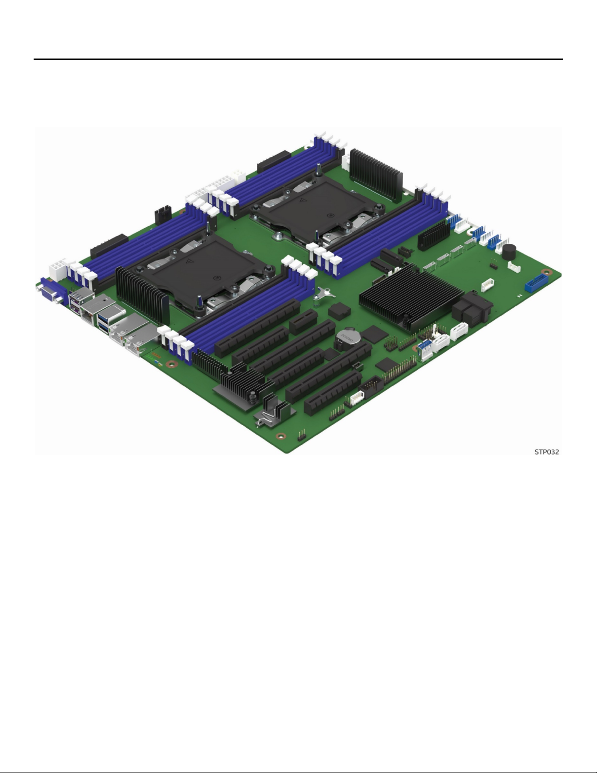
Figure 1. Intel® Server Board S2600STB ......................................................................................................................................... 15
Figure 2. Server board component / feature identification ..................................................................................................... 17
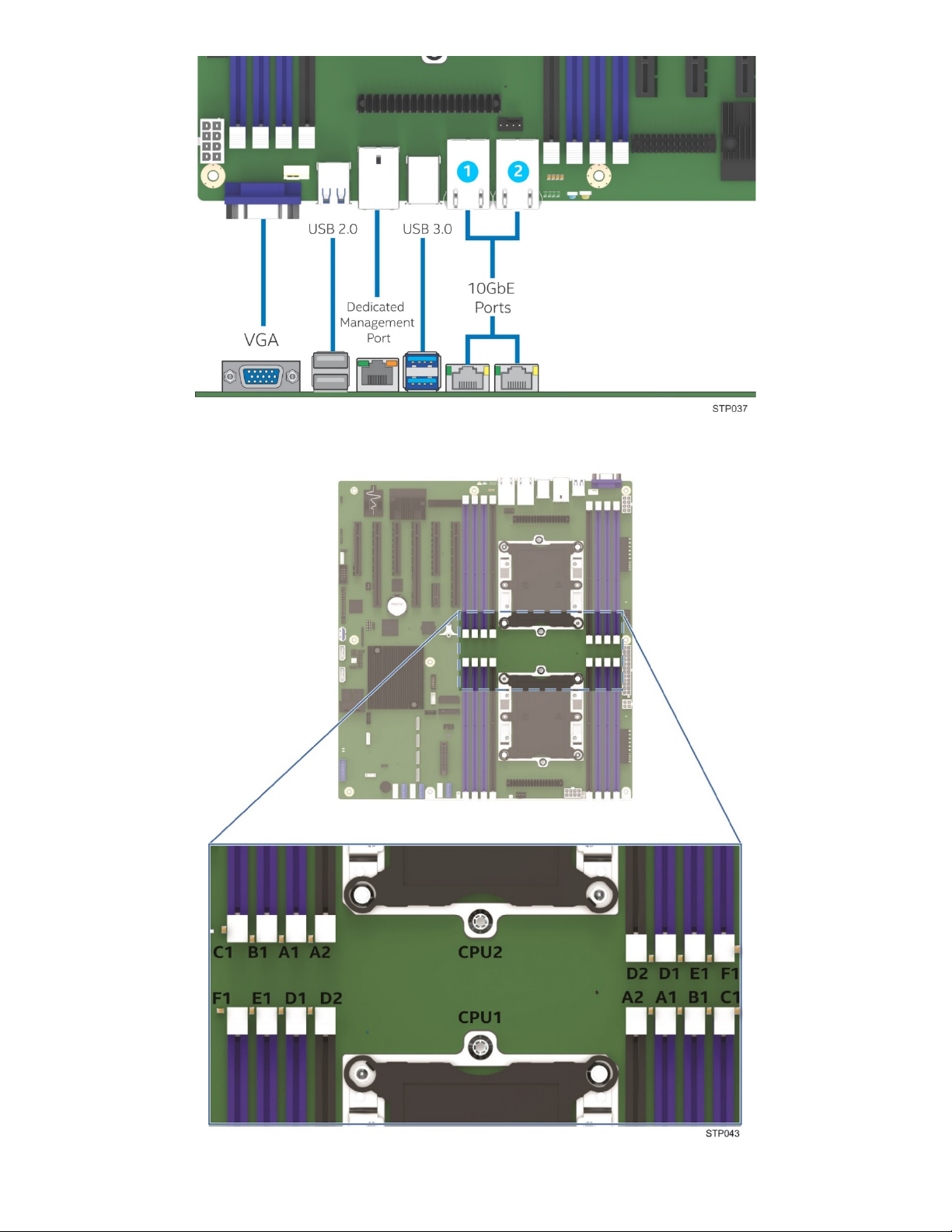
Figure 3. Intel® Server Board S2600ST product family external I/O connector layout ............................................... 18
Figure 4. Intel® Light Guided Diagnostics - DIMM fault LEDs .................................................................................................. 18
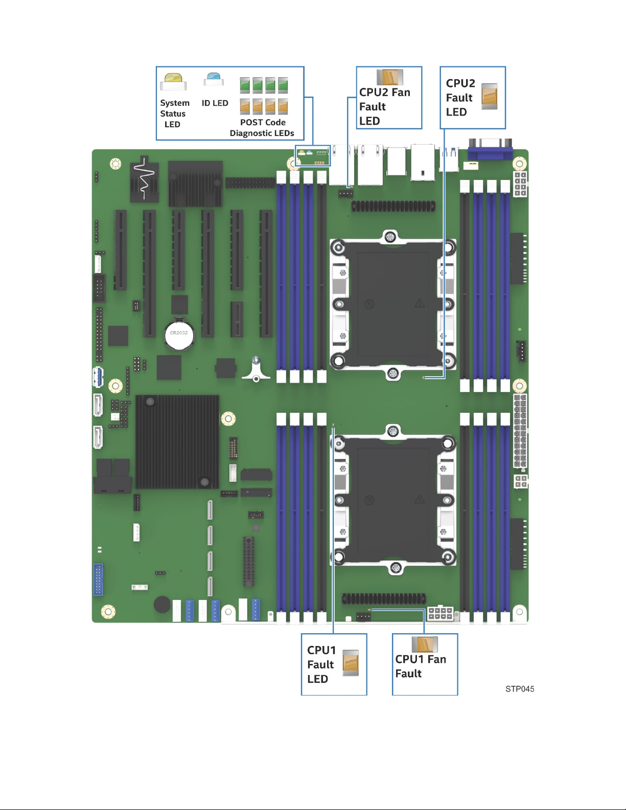
Figure 5. Intel® Light Guided Diagnostics – LED identification ............................................................................................... 19
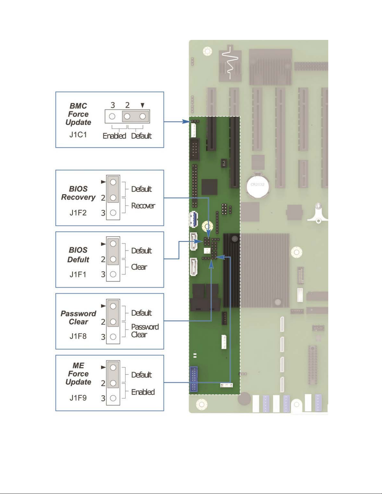
Figure 6. Jumper block identification ............................................................................................................................................... 20
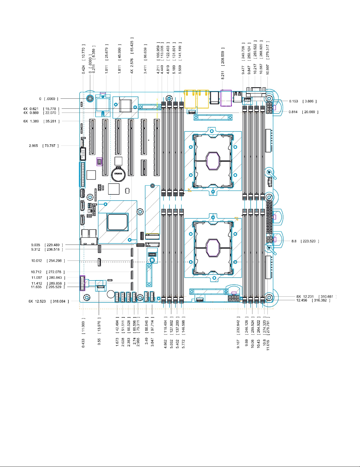
Figure 7. Primary side keep out zone and component height restrictions ....................................................................... 21
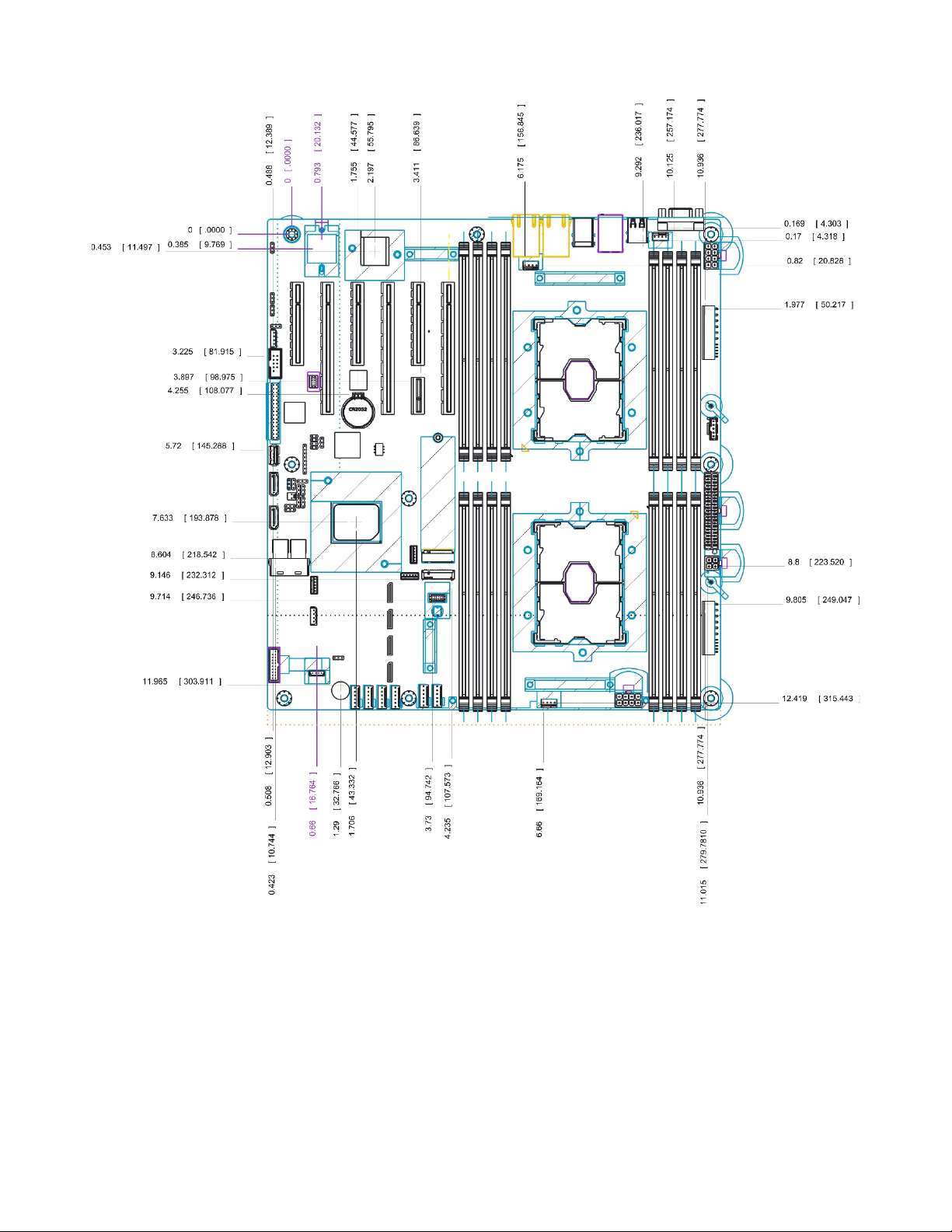
Figure 8. Secondary side keep out zone ......................................................................................................................................... 22
Figure 9. Mounting holes ....................................................................................................................................................................... 23
Figure 10. Mounting holes continued ............................................................................................................................................... 24
Figure 11. Major components and connectors (1 of 3) ............................................................................................................. 25
Figure 12. Major components and connectors (2 of 3) ............................................................................................................. 26
Figure 13. Major components and connectors (3 of 3) ............................................................................................................. 27
Figure 14. Intel® Server Board S2600ST product family block diagram ............................................................................ 28
Figure 15. Processor socket assembly ............................................................................................................................................. 32
Figure 16. Processor socket assembly and protective dust cover ....................................................................................... 32
Figure 17. Processor heat sink module (PHM) components and processor socket reference diagram ............... 33
Figure 18. Processor heat sink module (PHM) sub-assembly ................................................................................................ 33
Figure 19. Fully assembled processor heat sink module (PHM) ........................................................................................... 34
Figure 20. Two systems connected through PCIe* Non-Transparent Bridge (NTB) ..................................................... 42
Figure 21. Memory sub-system architecture ................................................................................................................................. 43
Figure 22. Intel® Server Board S2600ST product family memory slot layout ................................................................. 45
Figure 23. Optional Intel® QuickAssist Technology bridge cable installed ...................................................................... 50
Figure 24. Intel® QuickAssist Technology bridge cable – iPC AXXSTCBLQAT ................................................................ 50
Figure 25. PCIe* slots ............................................................................................................................................................................... 51
Figure 26. M.2 connectors ..................................................................................................................................................................... 52
Figure 27. Onboard OCuLink connectors ....................................................................................................................................... 53
Figure 28. Intel® Volume Management Device (Intel® VMD) for NVMe* SSDs ................................................................. 53
Figure 29. VMD support disabled in BIOS setup .......................................................................................................................... 55
Figure 30. VMD support enabled in BIOS setup .......................................................................................................................... 55
Figure 31. Intel® VROC basic architecture overview ................................................................................................................... 56
Figure 32. Intel® VROC upgrade key .................................................................................................................................................. 56
Figure 33. SATA RAID 5 upgrade key ................................................................................................................................................ 61
Figure 34. Network interface connectors ........................................................................................................................................ 61
Figure 35. External RJ45 network interface controller (NIC) port LED definition .......................................................... 62
Figure 36. SFP+ LAN Riser Option...................................................................................................................................................... 62
Figure 37. SFP+ LAN Riser Option Support ................................................................................................................................... 63
Figure 38. BIOS setup security options ............................................................................................................................................ 64
Figure 39. Onboard TPM Connector ................................................................................................................................................. 66
Figure 40. High-level fan speed control process ......................................................................................................................... 76
9
Page 10

Intel® Server Board S2600ST Product Family Technical Product Specification
Figure 41. Intel® RMM4 Lite placement ............................................................................................................................................ 80
Figure 42. Dedicated Management Port .......................................................................................................................................... 80
Figure 43. Jumper block locations and pins .................................................................................................................................. 94
Figure 44. DIMM fault LEDs ................................................................................................................................................................... 99
Figure 45. System status LED and ID LED identification ....................................................................................................... 100
Figure 46. POST diagnostic LED location and definition ....................................................................................................... 105
Figure 47. Intel® Server Chassis P4304XXMFEN2 feature overview ................................................................................ 125
Figure 48. Intel® Server Chassis P4304XXMUXX feature overview .................................................................................. 126
Figure 49. Chassis-only building block (no front drive bay configuration) .................................................................... 126
Figure 50. Intel® Server Chassis P4304XXMFEN2/P4304XXMUXX front panel .......................................................... 127
Figure 51. P4304XXMFEN2 back panel ........................................................................................................................................ 127
Figure 52. Intel® Server Chassis P4304XXMUXX back panel .............................................................................................. 127
Figure 53. Drive tray LED identification ........................................................................................................................................ 128
10
Page 11

Intel® Server Board S2600ST Product Family Technical Product Specification
List of Tables
Table 1. Reference Documents ........................................................................................................................................................... 13
Table 2. Intel® Server Board S2600ST product family common feature set ................................................................... 16
Table 3. POST hot keys .......................................................................................................................................................................... 29
Table 4. Intel® Xeon® Processor Scalable Family Feature Comparison .............................................................................. 35
Table 5. Mixed processor configurations error summary ........................................................................................................ 39
Table 6. CPU – PCIe* port routing ...................................................................................................................................................... 41
Table 7. DDR4 RDIMM and LRDIMM support ................................................................................................................................ 44
Table 8. Memory RAS Features ........................................................................................................................................................... 47
Table 9. Intel® VROC upgrade key options ..................................................................................................................................... 57
Table 10. SATA and sSATA Controller Feature Support .......................................................................................................... 57
Table 11. SATA and sSATA controller BIOS utility setup options ........................................................................................ 58
Table 12. Onboard Network interface controller (NIC) LED Definition .............................................................................. 62
Table 13. SFP+ LAN Riser LED Definition ........................................................................................................................................ 63
Table 14. BIOS security configuration TPM states ...................................................................................................................... 67
Table 15. BIOS security configuration TPM administrative controls .................................................................................. 68
Table 16. Power control sources ........................................................................................................................................................ 71
Table 17. ACPI power states ................................................................................................................................................................. 71
Table 18. Component fault LEDs ........................................................................................................................................................ 78
Table 19. Intel® Remote Management Module 4 (Intel® RMM4) options ........................................................................... 79
Table 20. Standard and advanced server management features ......................................................................................... 79
Table 21. Main Power Connector Pin-out (“MAIN_PWR_CONN”) ......................................................................................... 86
Table 22. CPU1 Power Connector Pin-out (“CPU_1_PWR”) ................................................................................................... 87
Table 23. CPU2 Power Connector Pin-out (“CPU_2_PWR”) ................................................................................................... 88
Table 24. Auxiliary Power-in Connector Pin-out ("AUX_PWR_IN”) ...................................................................................... 88
Table 25. Front Panel Header Pin-out .............................................................................................................................................. 88
Table 26. Front Panel USB 3.0 Connector Pin-out ..................................................................................................................... 89
Table 27. SATA 6 Gbps Connector Pin-out .................................................................................................................................... 89
Table 28. Mini-SAS HD Connectors for SATA 6 Gbps Pin-out ............................................................................................... 90
Table 29. M.2 Connector Pin-outs (for SATA & PCIe* modules) ........................................................................................... 91
Table 30. 6-Pin System Fan Connector Pin-out ........................................................................................................................... 92
Table 31. 4-pin System Fan Connector Pin-out ........................................................................................................................... 92
Table 32. CPU Fan Connector Pin-out ............................................................................................................................................. 92
Table 33. I
Table 34. Serial Port A Connector Pin-out ..................................................................................................................................... 93
Table 35. PMBUS Connector Pin-out ............................................................................................................................................... 93
Table 36. Chassis Intrusion Header Pin-out .................................................................................................................................. 93
Table 37. System status LED state detail ..................................................................................................................................... 101
Table 38. BMC Boot/Reset Status LED Indicators .................................................................................................................... 102
Table 39.Server Board Environmental Limits ......................................................................................................................... 103
Table 40. POST progress code LED example ............................................................................................................................. 105
11
2
C Header B Pin-out (“HSBP_I2C_B”) ........................................................................................................................... 93
Page 12

Intel® Server Board S2600ST Product Family Technical Product Specification
Table 41. MRC progress codes ......................................................................................................................................................... 106
Table 42. MRC Fatal Error Codes ..................................................................................................................................................... 107
Table 43. POST progress codes ....................................................................................................................................................... 108
Table 44. POST error codes and messages ................................................................................................................................ 116
Table 45. POST error beep codes ................................................................................................................................................... 121
Table 46. Integrated BMC beep codes .......................................................................................................................................... 122
Table 47. Volatile and non-volatile components on the Intel® Server Board S2600ST product family ........... 123
Table 48. Volatile and non-volatile components on the LAN riser ................................................................................... 123
Table 49. Drive status LED states .................................................................................................................................................... 128
Table 50. Drive activity LED states .................................................................................................................................................. 128
Table 51. PCIe* SSD drive status LED states .............................................................................................................................. 128
Table 52. Environmental Limits ....................................................................................................................................................... 129
Table 53. System in “Normal” Operating Mode for Systems with Fan Redundancy ................................................. 131
Table 51. System in “Fan Fail” Operating Mode for Systems with Fan Redundancy ................................................ 134
Table 52. System in “Normal” Operating Mode for Systems without Fan Redundancy .......................................... 137
Table 53. System in “Throttling” Operating Mode for Systems with Fan Redundancy ............................................ 140
12
Page 13

Intel® Server Board S2600ST Product Family Technical Product Specification
Document
Classification
Intel® Server System BMC Firmware External Product Specification for Intel® Xeon®
processor Scalable family
Intel® Server System BIOS External Product Specification for Intel® Xeon® processor
Scalable family
Intel® C620 Series Chipset Platform Controller Hub External Design Specification
Intel Confidential
Intel® Xeon® processor Scalable Family Server Processor External Design Specification
Volume 1, Volume 2 Part A, Volume 2 Part B, Volume 3
Advanced Configuration and Power Interface Specification. Revision 3.0 (2004)
http://www.acpi.info/
Intelligent Platform Management Interface Specification, v2.0 (2004)
Public
Intelligent Platform Management Bus Communications Protocol Specification, v1.0
(1998)
Platform Support for Serial-over-LAN (SOL), TMode, and Terminal Mode External
Architecture Specification, Version 1.1 (2002)
Intel® Remote Management Module User Guide
Public
Alert Standard Format (ASF) Specification, Version 2.0 (2003), ©2000-2003,
Distributed Management Task Force, Inc., http://www.dmtf.org
SmaRT & CLST Architecture on Intel Systems and Power Supplies Specification
Public
Intel® Remote Management Module 4 Technical Product Specification
Public
Intel® Remote Management Module 4 and Integrated BMC Web Console User Guide
Public
1. Introduction
This Technical Product Specification (TPS) provides a high level overview of the features, functions, and
architecture of the Intel® Server Board S2600ST product family.
For more in-depth technical information, refer to the documents listed in Table 1.
Note: Some of the documents listed in the following table are classified as “Intel Confidential”. These
documents are made available under a Non-Disclosure Agreement (NDA) with Intel and must be ordered
through your local Intel representative.
Table 1. Reference Documents
Document Title
Intel Confidential
Intel Confidential
Intel Confidential
Public
Public
Public
Public
13
Page 14

Intel® Server Board S2600ST Product Family Technical Product Specification
1.1 Chapter Outline
This document is divided into the following chapters:
• Chapter 1 – Introduction
• Chapter 2 – Server Board Overview
• Chapter 3 – Processor Support
• Chapter 4 – PCI Express* (PCIe*) Support
• Chapter 5 – Memory Support
• Chapter 6 – System I/O
• Chapter 7 – System Security
• Chapter 8 – Platform Management
• Chapter 9 – Standard and Advanced Server Management Features
• Chapter 10 – On-Board Connector and Header Overview
• Chapter 11 – Reset and Recovery Jumpers
• Chapter 12 – Light-Guided Diagnostics
• Chapter 13 – Design and Environmental Specifications
• Appendix A – Integration and Usage Tips
• Appendix B – Post Code Diagnostic LED Decoder
• Appendix C – Post Code Errors
• Appendix D – Statement of Volatility
• Appendix E – Supported Intel Server Chassis
• Appendix F – Glossary
1.2 Intel® Server Board Use Disclaimer
Intel® Server Boards support add-in peripherals and contain a number of high-density very large scale
integration (VLSI) and power delivery components that need adequate airflow to cool. Intel ensures through
its own chassis development and testing that when Intel server building blocks are used together, the fully
integrated system will meet the intended thermal requirements of these components. It is the responsibility
of the system integrator who chooses not to use Intel developed server building blocks to consult vendor
datasheets and operating parameters to determine the amount of airflow required for their specific
application and environmental conditions. Intel Corporation cannot be held responsible if components fail
or the server board does not operate correctly when used outside any of its published operating or nonoperating limits.
14
Page 15
Intel® Server Board S2600ST Product Family Technical Product Specification
2. Server Board Family Overview
The Intel® Server Board S2600ST product family is a monolithic printed circuit board assembly with features
that are intended for flexibility in scalable performance environments. This server board is designed to
support the Intel® Xeon® processor Scalable family. Previous generation Intel® Xeon® processors are not
supported.
Figure 1. Intel® Server Board S2600STB
15
Page 16

Intel® Server Board S2600ST Product Family Technical Product Specification
Intel® Server Board Feature
iPC – S2600STB
iPC –S2600STQ
Processor
2 – LGA3647-0 (Socket P) processor sockets
Note: Previous generation Intel® Xeon® processors are not supported.
Memory
16 total DIMM slots
DDR4 standard voltage of 1.2 V
Intel® C62x Series Chipset
Intel® C624 Chipset
Intel® C628 Chipset
Intel® QuickAssist Technology
No
Yes
Local Area Network (LAN)
Dual port RJ45 10 GbE on board
Optional riser aligned to Slot 5 with two 10 Gb SFP+ connectors
Onboard PCIe* NVMe*
• (4) – OCuLink connectors
(accessory option)
• (2) – OCuLink connectors
option)
Onboard SATA
12 x SATA 6 Gbps ports (6 Gb/s, 3 Gb/s and 1.5 Gb/s transfer rates are supported)
PCIe* Add-in Card Slots
• Slot 1: PCIe* 3.0 x8 slot (x8 electrical) handled by CPU2
• Slot 6: PCIe* 3.0 x16 slot (x16 electrical) handled by CPU1 (riser capable)
Video
• Integrated 2D video controller
(1) – DB-15 external connector
USB
• (2) – external USB 2.0 ports
(1) – 2x10 pin connector providing front panel support for (2) USB 2.0 / 3.0 ports
Serial Port
(1) – internal DH-10 serial port A connector
Server Management
• Integrated baseboard management controller, IPMI 2.0 compliant
• Advanced server management via Intel® RMM4 Lite (accessory option)
Security
Trusted platform module 2.0 (Rest of World) – iPC- AXXTPMENC8 (accessory option)
Trusted platform module 2.0 (China Version) – iPC- AXXTPME8 (accessory option)
System Fan Support
• (2) – 4-pin processor fan headers
• (1) – 4-pin rear system fan header
2.1 Server Board Feature Set
Table 2. Intel® Server Board S2600ST product family common feature set
Supports (1) or (2) Intel® Xeon® processor Scalable family with maximum TDP of 205 W.
2 UPI* links between processors
8 DIMM slots across 6 memory channels per processor
• 1 DIMM slot per memory channel on 4 channels
• 2 DIMM slots per memory channel on 2 channels
Supported memory: Registered DDR4 (RDIMM), Load Reduced DDR4 (LRDIMM)
Memory data transfer rate up to 2666 MT/s (processor SKU dependent)
• Intel® VMD support
• Intel® RSTe VROC support
• (2) – single port 7-pin SATA connectors
• (2) – M.2 connectors – SATA / PCIe*
• (2) – 4-port mini- SAS high density (HD) (SFF-8643) connectors
Embedded SATA software RAID
• Intel® RSTe 5.0
• Intel® Embedded Server RAID Technology 2 1.60 with optional RAID 5 key support (see
section 6.3.6 for details)
• Slot 2: PCIe* 3.0 x16 slot (x16 electrical) handled by CPU2 (riser capable)
• Slot 3: PCIe* 3.0 x8 slot (x8 electrical) handled by CPU2
• Slot 4: PCIe* 3.0 x16 slot (x16 electrical) handled by CPU2
• Slot 5: PCIe* 3.0 x8 slot (x8 electrical) handled by CPU1
• 16 MB of DDR4 video memory
•
• (2) – external USB 3.0 ports
• (1) – internal USB 3.0 type A connector
•
• Intel® VMD support
• Intel® RSTe VROC support (accessory
• Support for Intel® Server Management software
• Dedicated onboard RJ45 management port
16
• (6) – 6-pin front system fan headers
Page 17

Intel® Server Board S2600ST Product Family Technical Product Specification
2.2 Server Board Component / Feature Identification
Figure 2. Server board component / feature identification
17
Page 18
Intel® Server Board S2600ST Product Family Technical Product Specification
Figure 3. Intel® Server Board S2600ST product family external I/O connector layout
Figure 4. Intel® Light Guided Diagnostics - DIMM fault LEDs
18
Page 19
Intel® Server Board S2600ST Product Family Technical Product Specification
Figure 5. Intel® Light Guided Diagnostics – LED identification
19
Page 20
Intel® Server Board S2600ST Product Family Technical Product Specification
Figure 6. Jumper block identification
See Chapter 11 for additional details on reset and recovery jumpers.
20
Page 21
Intel® Server Board S2600ST Product Family Technical Product Specification
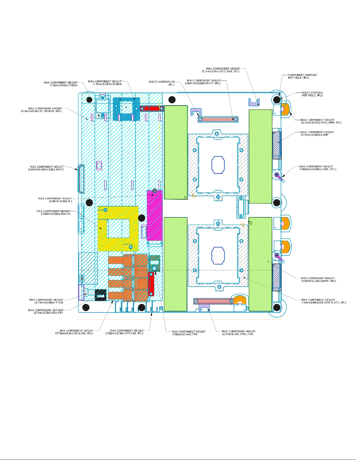
2.3 Server Board Mechanical Drawings
Figure 7. Primary side keep out zone and component height restrictions
21
Page 22
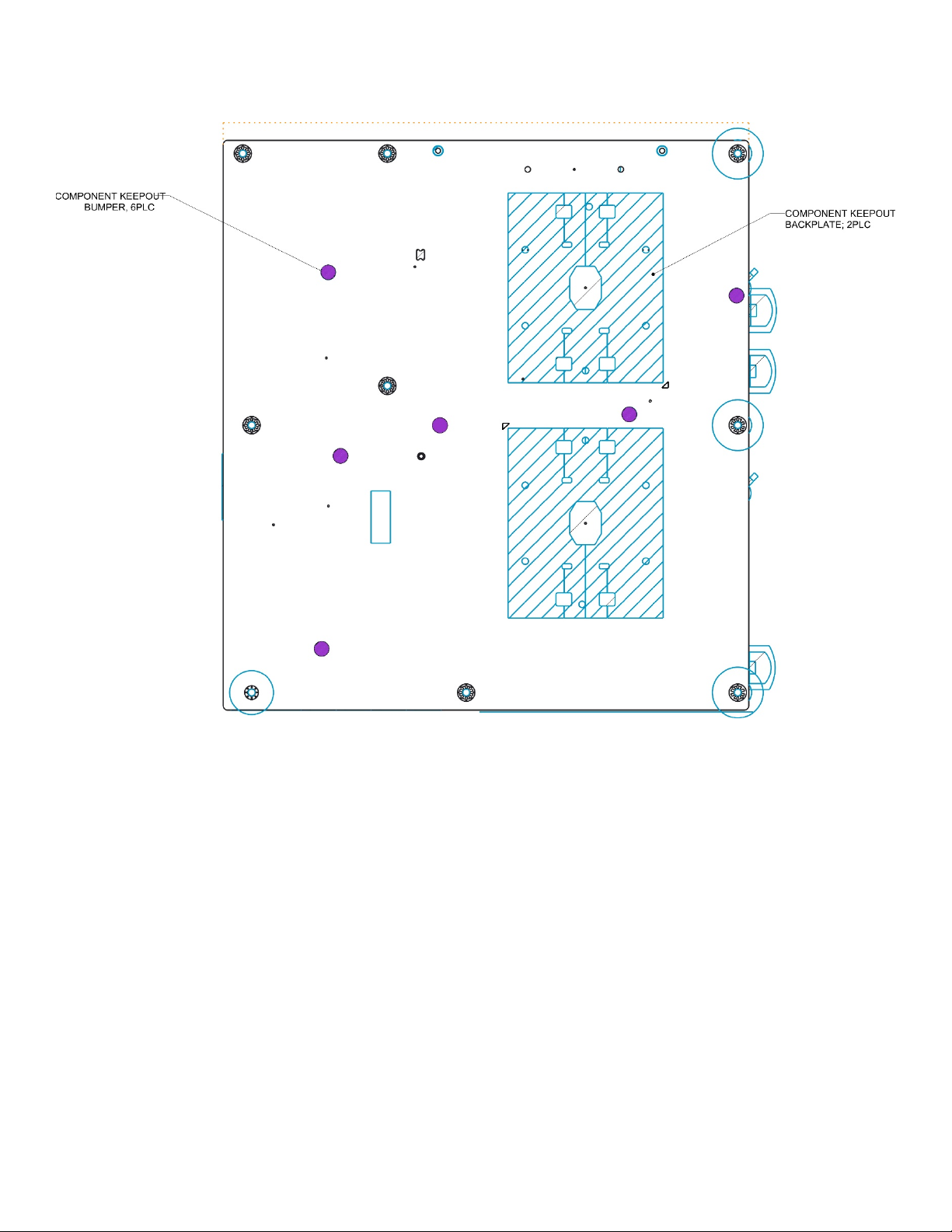
Intel® Server Board S2600ST Product Family Technical Product Specification
Figure 8. Secondary side keep out zone
22
Page 23
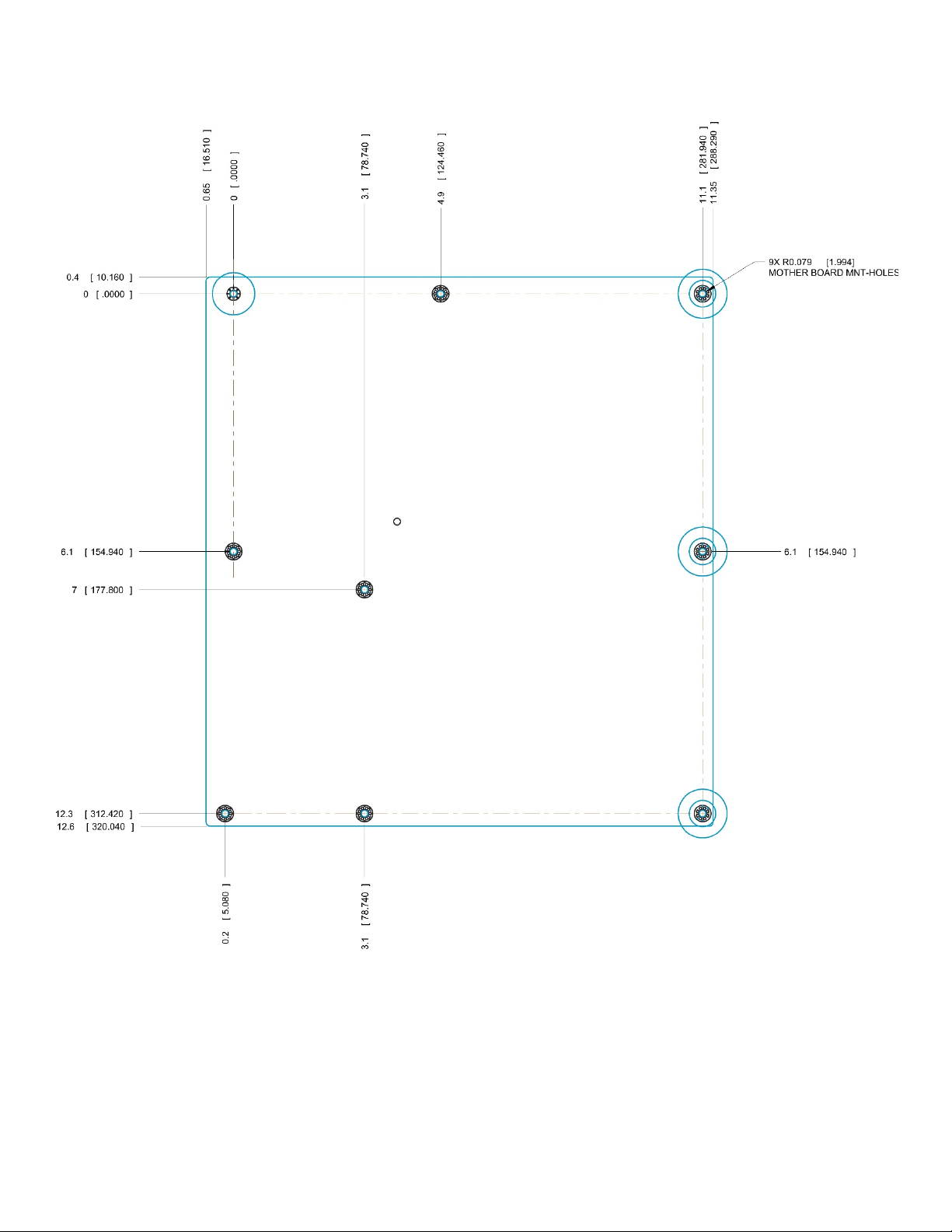
Intel® Server Board S2600ST Product Family Technical Product Specification
Figure 9. Mounting holes
23
Page 24
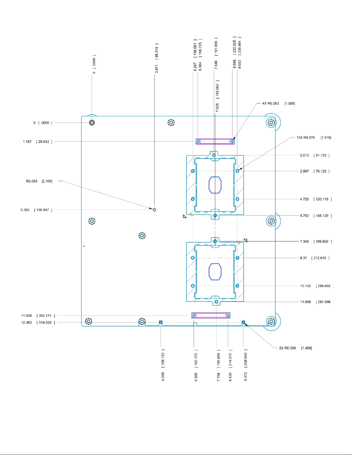
Intel® Server Board S2600ST Product Family Technical Product Specification
Figure 10. Mounting holes continued
24
Page 25
Intel® Server Board S2600ST Product Family Technical Product Specification
Figure 11. Major components and connectors (1 of 3)
25
Page 26
Intel® Server Board S2600ST Product Family Technical Product Specification
Figure 12. Major components and connectors (2 of 3)
26
Page 27

Intel® Server Board S2600ST Product Family Technical Product Specification
Figure 13. Major components and connectors (3 of 3)
27
Page 28
Intel® Server Board S2600ST Product Family Technical Product Specification
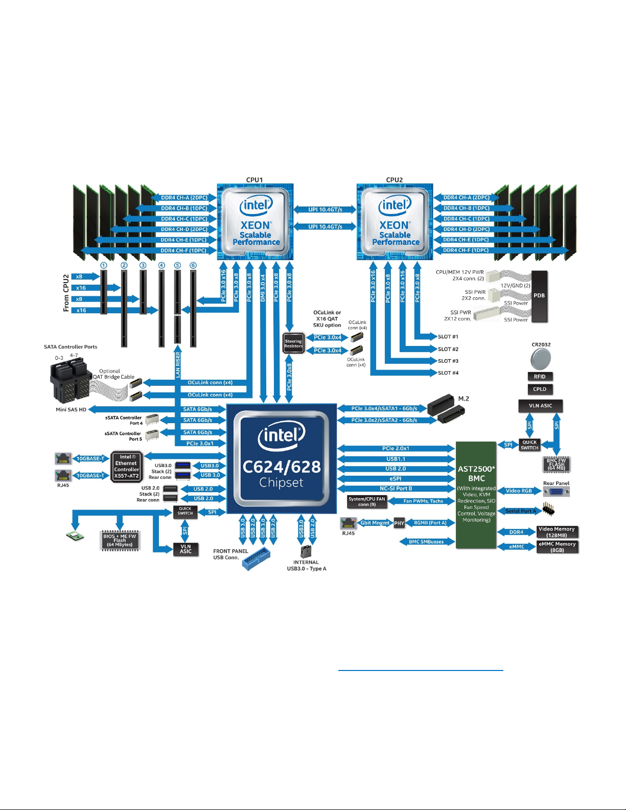
2.4 Product Architecture Overview
The architecture of the Intel® Server Board S2600ST product family is developed around the integrated
features and functions of the Intel® Xeon® processor Scalable family, the Intel® C624 and C628 chipsets, and
the Aspeed* AST2500 Baseboard Management Controller (BMC).
The following diagram provides an overview of the server board architecture, showing the features and
interconnects of each of the major sub-system components.
Figure 14. Intel® Server Board S2600ST product family block diagram
2.5 System Software Stack
System software is pre-programmed by Intel on the server board during the board assembly process,
making the server board functional at first power on after system integration. However, to ensure the most
reliable system operation, it is highly recommended to visit http://downloadcenter.intel.com
available system updates.
System updates can be performed in a number of operating environments, including the embedded Unified
Extensible Firmware Interface (UEFI) shell using the UEFI only System Update Package (SUP), or under Intel
supported operating systems using the Intel® One Boot Flash Update (Intel® OFU) utility.
28
for the latest
Page 29

Intel® Server Board S2600ST Product Family Technical Product Specification
Hot Key
Function
<F2>
Enter the BIOS setup utility
<F6>
Pop-up BIOS boot menu
<F12>
Network boot
<Esc>
Switch from logo screen to diagnostic screen
<Pause>
Stop POST temporarily
As part of the initial system integration process, system integrators must program system configuration data
onto the server board using the Field Replaceable Unit / Sensor Data Record (FRUSDR) utility to ensure the
embedded platform management subsystem is able to provide the best performance and cooling for the
final system configuration. The FRUSDR utility is included in the uEFI SUP and Intel OFU packages.
Refer to the following Intel documents for more in-depth information about the system software stack and
their functions:
• Intel® Server System BMC Firmware External Product Specification for Intel® Xeon® Processor Scalable
Family – Intel NDA Required
• Intel® Server System BIOS External Product Specification for Intel® Xeon® processor Scalable family –
Intel NDA Required
2.5.1 Hot Keys Supported During Power-On Self-Test (POST)
Certain hot keys are recognized during power-on self-test (POST). A hot key is a key or key combination that
is recognized as an unprompted command input by the system operator. In most cases, hot keys are
recognized even while other processing is in progress.
The Basic Input/Output System (BIOS) supported hot keys are only recognized by the BIOS during the
system boot time POST process. BIOS supported hot keys are no longer recognized once the POST process
has completed and the operating system boot process has begun.
Table 3 provides a list of BIOS supported hot keys.
Table 3. POST hot keys
2.5.1.1 POST Logo and Diagnostic Screens
With the BIOS Setup Utility set to Quiet Boot (default), the BIOS will display a splash screen to the display
monitor during the POST process. Pressing the <ESC> key will close the splash screen and open a POST
Diagnostic / Information screen in its place.
The factory default splash screen is that of an Intel Logo. A custom OEM splash screen can be installed to a
designated flash memory location to over-ride the factory default.
If a splash screen is not present in the BIOS flash memory space, or if Quiet Boot is disabled in BIOS Setup,
the POST diagnostic screen is displayed during POST with a summary of the system configuration
information. The POST diagnostic screen is purely a text mode screen, as opposed to the graphics mode
logo screen.
If console redirection is enabled in the BIOS setup utility, the quiet boot setting is disregarded and the text
mode diagnostic screen is displayed unconditionally. This is due to the limitations of console redirection,
which transfers data in a mode that is not graphics-compatible.
29
Page 30

Intel® Server Board S2600ST Product Family Technical Product Specification
2.5.1.2 BIOS Boot Pop-Up Menu
The BIOS Boot Specification (BBS) provides a boot pop-up menu that can be invoked by pressing the <F6>
key during POST. The BBS pop-up menu displays all available boot devices. The boot order in the pop-up
menu is not the same as the boot order in the BIOS setup utility. The pop-up menu simply lists all of the
available devices from which the system can be booted, and allows a manual selection of the desired boot
device.
When an Administrator password is installed in the BIOS setup utility, the Administrator password is
required to access the boot pop-up menu. If a User password is entered, the user is taken directly to the boot
manager in the BIOS setup utility only allowing the system to boot in the order previously defined by the
administrator.
2.5.1.3 Entering BIOS Setup
To enter the BIOS setup utility using a keyboard (or emulated keyboard), press the <F2> function key during
boot time when the OEM or Intel logo screen or the POST diagnostic screen is displayed.
The following instructional message is displayed on the diagnostic screen or under the quiet boot logo
screen:
Press <F2> to enter setup, <F6> Boot Menu, <F12> Network Boot
Note: With a USB keyboard, it is important to wait until the BIOS discovers the keyboard and beeps; until the
USB controller has been initialized and the keyboard activated, key presses are not read by the system.
When the BIOS setup utility is entered, the main screen is displayed initially. However, if a serious error
occurs during POST, the system enters the BIOS setup utility and displays the error manager screen instead
of the main screen.
Refer to the following Intel document for additional BIOS setup utility information:
• Intel® Server System BIOS External Product Specification for Intel® Xeon® processor Scalable family –
Intel NDA Required
2.5.2 BIOS Update Capability
To bring BIOS fixes or new features into the system, it is necessary to replace the current installed BIOS
image with an updated one. The BIOS image can be updated using a standalone IFLASH32 utility in the UEFI
shell or using the OFU utility program under a supported operating system. Full BIOS update instructions are
provided with update packages downloaded from the Intel website.
2.5.3 BIOS Recovery
If a system is unable to boot successfully to an OS, hangs during POST, or even hangs and fails to start
executing POST, it may be necessary to perform a BIOS recovery procedure to replace a defective copy of
the primary BIOS
The BIOS provides three mechanisms to start the BIOS recovery process, which is called recovery mode:
• The recovery mode jumper causes the BIOS to boot in recovery mode. See Figure 6 for jumper
location.
• At power on, if the BIOS boot block detects a partial BIOS update was performed, the BIOS
automatically boots in recovery mode.
• The baseboard management controller (BMC) asserts the recovery mode general purpose
input/output (GPIO) in case of partial BIOS update and FRB2 timeout.
30
Page 31

Intel® Server Board S2600ST Product Family Technical Product Specification
The BIOS recovery takes place without any external media or mass storage device as it uses a backup BIOS
image inside the BIOS flash in recovery mode.
Note: The recovery procedure is included here for general reference. However, if in conflict, the instructions
in the BIOS release notes are the definitive version.
When the BIOS recovery jumper is set, the BIOS begins by logging a recovery start event to the System Event
Log (SEL). It then loads and boots with a backup BIOS image residing in the BIOS flash device. This process
takes place before any video or console is available. The system boots to the embedded UEFI shell, and a
recovery complete event is logged to the SEL. From the UEFI shell, the BIOS can then be updated using a
standard BIOS update procedure defined in update instructions provided with the system update package
downloaded from the Intel website. Once the update has completed, switch the recovery jumper back to its
default position and power cycle the system.
If the BIOS detects a partial BIOS update or the BMC asserts recovery mode GPIO, the BIOS boots in recovery
mode. The difference is that the BIOS boots up to the error manager page in the BIOS setup utility. In the
BIOS Setup utility, a boot device, shell or Linux for example, could be selected to perform the BIOS update
procedure under shell or OS environment.
Note: Prior to performing a recovery boot, be sure to check the BIOS release notes and verify the recovery
procedure shown in the release notes. This process needs to be followed step by step to ensure the stability
of the system once it is completed.
2.5.4 Field Replaceable Unit (FRU) and Sensor Data Record (SDR) Data
As part of the initial system integration process, the server board/system must have the proper Field
Replaceable Unit (FRU) and Sensor Data Record (SDR) data loaded. This ensures that the embedded platform
management system is able to monitor the appropriate sensor data and operate the system with best
cooling and performance. The BMC supports automatic configuration of the manageability subsystem after
changes have been made to the system’s hardware configuration. Once the system integrator has performed
an initial FRU/SDR package update, subsequent auto-configuration occurs without the need to perform
additional SDR updates or provide other user input to the system when any of the following components are
added or removed.
• Processors
• Intel Add-in cards / modules
• Power supplies
• Fans
• Fan options (for example, upgrade from non-redundant cooling to redundant cooling)
• Intel® Xeon Phi™ coprocessor cards
• Hot swap backplane
• Front panel
Note: The system may not operate with best performance or best/appropriate cooling if the proper FRU and
SDR data is not installed. The system fans may operate at full speed 100% all the time if the FRUSDR utility
is not run after the initial board integration and system configuration.
The FRU and SDR data can be updated using a standalone FRUSDR utility in the UEFI shell, or can be done
using the OFU utility program under a supported operating system. Full FRU and SDR update instructions are
provided with the appropriate system update package (SUP) or OFU utility which can be downloaded from
the Intel website.
31
Page 32

Intel® Server Board S2600ST Product Family Technical Product Specification
3. Processor Support
The server board includes two Socket-P0 LGA3647-0 processor sockets compatible with the Intel® Xeon®
processor Scalable family with a maximum Thermal Design Power (TDP) of 205 W. Visit http://ark.intel.com/
for a complete list of supported processors.
Note: Previous generation Intel® Xeon® processors are not supported on the Intel® Server Boards described
in this document.
3.1 Processor Heat Sink Module (PHM) and Processor Socket Assembly
Each processor socket of the server board is pre-assembled and includes a back plate, LGA3647-0 processor
socket, and a bolster plate assembly. The illustration in Figure 15 identifies each sub-assembly component.
Figure 15. Processor socket assembly
Server boards with no processors installed have a plastic protective dust cover installed over each processor
socket assembly. The protective covers must be carefully removed before processor installation, as shown in
Figure 16.
Figure 16. Processor socket assembly and protective dust cover
32
Page 33

Intel® Server Board S2600ST Product Family Technical Product Specification
This generation server board introduces the concept of the Processor Heat Sink Module (PHM) shown in
Figure 17, Figure 18, and Figure 19.
Processor installation requires that the processor be attached to the processor heat sink prior to
installation onto the server board.
Figure 17. Processor heat sink module (PHM) components and processor socket reference diagram
Figure 18. Processor heat sink module (PHM) sub-assembly
33
Page 34

Intel® Server Board S2600ST Product Family Technical Product Specification
Figure 19. Fully assembled processor heat sink module (PHM)
3.2 Processor Thermal Design Power (TDP) Support
To allow for optimal operation and provide for best long-term reliability of Intel processor-based systems,
the processor must remain within the defined minimum and maximum case temperature (TCASE)
specifications. Thermal solutions not designed to provide sufficient thermal capability may affect the longterm reliability of the processor and system. The server board described in this document is designed to
support the Intel® Xeon® processor Scalable family TDP guidelines up to and including 205 W.
Disclaimer Note: Intel® Server Boards contain a number of high-density very large scale integration (VLSI)
and power delivery components that need adequate airflow to cool. Intel ensures, through its own chassis
development and testing, that when Intel server building blocks are used together, the fully integrated
system meets the intended thermal requirements of these components. It is the responsibility of system
integrators who choose not to use Intel developed server building blocks to consult vendor datasheets and
operating parameters to determine the amount of airflow required for their specific applications and
environmental conditions. Intel Corporation cannot be held responsible if components fail or the server
board does not operate correctly when used outside any of its published operating or non-operating limits.
34
Page 35

Intel® Server Board S2600ST Product Family Technical Product Specification
Feature
Platinum 81xx
Gold 61xx
Gold 51xx
Silver 41xx
Bronze 31xx
# of Intel® UPI Links
3 3 2
2
2
Intel UPI Speed
10.4 GT/s
10.4 GT/s
10.4 GT/s
9.6 GT/s
9.6 GT/s
2S-2UPI
8S- 3UPI
Node Controller Support
Yes
Yes
No
No
No
# of Memory Channels
6 6 6
6
6
Max DDR4 Speed
2666
2666
2400
2400
2133
768GB
1.5TB (select SKUs)
768GB
1.5TB (select SKUs)
768GB
1.5TB (select SKUs)
RAS Capability
Advanced
Advanced
Advanced
Standard
Standard
Intel® Turbo Boost
Technology
Intel® HT Technology
Yes
Yes
Yes
Yes
No
Intel® AVX-512 ISA Support
Yes
Yes
Yes
Yes
Yes
Intel® AVX-512 - # of 512b
FMA Units
# of PCIe* Lanes
48
48
48
48
48
3.3 Intel® Xeon® Processor Scalable Family Overview
The Intel® Server Board S2600ST product family has support for the Intel® Xeon® processor Scalable family:
• Intel® Xeon® Bronze XXXX processor,
• Intel® Xeon® Silver XXXX processor,
• Intel® Xeon® Gold XXXX processor, and
• Intel® Xeon® Platinum XXXX processor,
where XXXX is the Intel defined processor SKU.
Table 4. Intel® Xeon® Processor Scalable Family Feature Comparison
2S-2UPI
2S-3UPI
4S-2UPI
4S-3UPI
2S-2UPI
4S-2UPI
2S-2UPI 2S-2UPI
768 GB 768 GB
Supported Topologies
Memory Capacity
2S-3UPI
4S-2UPI
4S-3UPI
Yes Yes Yes Yes No
2 2 1 1 1
The Intel® Xeon® processor Scalable family combines several key system components into a single processor
package, including the CPU cores, Integrated Memory Controller (IMC), and Integrated IO Module (IIO). The
processor includes many core and uncore features and technologies described in the following sections.
Core features:
• Intel® Ultra Path Interconnect (Intel® UPI) – up to 10.4 GT/s
• Intel® Speed Shift Technology
• Intel® 64 architecture
• Enhanced Intel SpeedStep® Technology
• Intel® Turbo Boost Technology 2.0
• Intel® Hyper-Threading Technology (Intel® HT Technology)
• Intel® Virtualization Technology for IA-32, Intel® 64 and Intel® Architecture (Intel® VT-x)
• Intel® Virtualization Technology for Directed I/O (Intel® VT-d)
• Execute Disable Bit
• Intel® Trusted Execution Technology (Intel® TXT)
• Intel® Advanced Vector Extensions 512 (Intel® AVX-512)
• Intel® Advanced Encryption Standard New Instructions (Intel® AES-NI)
Uncore features:
35
Page 36

Intel® Server Board S2600ST Product Family Technical Product Specification
• Up to 48 PCIe* lanes 3.0 lanes per CPU – 79GB/s bi-directional pipeline
• Six channels DDR4 memory support per CPU
• DMI3/PCIe 3.0 interface with a peak transfer rate of 8.0 GT/s.
• Non-Transparent Bridge (NTB) enhancements – three full duplex NTBs and 32 MSI-X vectors
• Intel® Volume Management Device (Intel® VMD) – manages CPU attached NVM Express* (NVMe*) solid
state drives (SSDs)
• Intel® Quick Data Technology
• Support for Intel® Node Manager 4.0
3.3.1 Intel® 64 Instruction Set Architecture (ISA)
Intel® 64 architecture is a 64-bit memory extension to the IA-32 architecture. Further details on Intel 64
architecture and programming model can be found at http://developer.intel.com/technology/intel64/.
3.3.2 Intel® Hyper-Threading Technology
The processor supports Intel® Hyper-Threading Technology (Intel® HT Technology), which allows an
execution core to function as two logical processors. While some execution resources such as caches,
execution units, and buses are shared, each logical processor has its own architectural state with its own set
of general-purpose registers and control registers. This feature must be enabled via the BIOS and requires
operating system support.
3.3.3 Enhanced Intel SpeedStep® Technology
Processors in the fifth generation Intel® Core™ processor family support Enhanced Intel SpeedStep®
Technology. The processors support multiple performance states, which allows the system to dynamically
adjust processor voltage and core frequency as needed to enable decreased power consumption and
decreased heat production. All controls for transitioning between states are centralized within the processor,
allowing for an increased frequency of transitions for more effective operation.
The Enhanced Intel SpeedStep Technology feature may be enabled and disabled by an option on the
processor configuration setup screen. By default Enhanced Intel SpeedStep Technology is enabled. If
disabled, the processor speed is set to the processor’s max TDP core frequency (nominal rated frequency).
3.3.4 Intel® Turbo Boost Technology 2.0
Intel® Turbo Boost Technology is featured on all processors in the fifth generation Intel® Core™ processor
family. Intel Turbo Boost Technology opportunistically and automatically allows the processor to run faster
than the marked frequency if the processor is operating below power, temperature, and current limits. This
results in increased performance for both multi-threaded and single-threaded workloads.
3.3.5 Intel® Virtualization Technology for IA-32, Intel® 64 and Intel® Architecture (Intel® VT-x)
Intel® Virtualization Technology for IA-32, Intel® 64 and Intel® Architecture (Intel® VT-x) provides hardware
support in the core to improve performance and robustness for virtualization. Intel VT-x specifications and
functional descriptions are included in the Intel® 64 and IA-32 Architectures Software Developer’s Manual.
3.3.6 Intel® Virtualization Technology for Directed I/O (Intel® VT-d)
Intel® Virtualization Technology for Directed I/O (Intel® VT-d) provides hardware support in the core and
uncore implementations to support and improve I/O virtualization performance and robustness.
3.3.7 Execute Disable Bit
Intel's Execute Disable Bit functionality can help prevent certain classes of malicious buffer overflow attacks
when combined with a supporting operating system. This allows the processor to classify areas in memory
by where application code can execute and where it cannot. When malicious code attempts to insert code in
the buffer, the processor disables code execution, preventing damage and further propagation.
36
Page 37

Intel® Server Board S2600ST Product Family Technical Product Specification
3.3.8 Intel® Trusted Execution Technology (Intel® TXT) for Servers
Intel® Trusted Execution Technology (Intel® TXT) defines platform-level enhancements that provide the
building blocks for creating trusted platforms. The Intel TXT platform helps to provide the authenticity of the
controlling environment such that those wishing to rely on the platform can make an appropriate trust
decision. The Intel TXT platform determines the identity of the controlling environment by accurately
measuring and verifying the controlling software.
3.3.9 Intel® Adavanced Vector Extension 512 (Intel® AVX-512)
The base of the 512-bit SIMD instruction extensions are referred to as Intel® Advanced Vector Extension 512
(Intel® AVX-512) foundation instructions. They include extensions of the Intel AVX family of SIMD
instructions but are encoded using a new encoding scheme with support for 512-bit vector registers, up to
32 vector registers in 64-bit mode, and conditional processing using opmask registers.
3.3.10 Intel® Advanced Encryption Standard New Instructions (Intel® AES-NI)
Intel® Advanced Encryption Standard New Instructions (Intel® AES-NI) is a set of instructions implemented in
all processors in the fifth generation Intel® Core™ processor family. This feature adds instructions to
accelerate encryption and decryption operations used in the Advanced Encryption Standard (AES). The Intel
AES-NI feature includes six additional Single Instruction Multiple Data (SIMD) instructions in the Intel®
Streaming SIMD Extensions instruction set.
The BIOS is responsible in POST to detect whether the processor has the Intel AES-NI instructions available.
Some processors may be manufactured without Intel AES-NI instructions.
The Intel AES-NI instructions may be enabled or disabled by the BIOS. Intel AES-NI instructions are in an
enabled state unless the BIOS has explicitly disabled them.
3.3.11 Intel® Node Manager (Intel® NM) 4.0
The Intel® C620 series chipset Intel® Management Engine (Intel® ME) supports Intel® Node Manager (Intel®
NM) technology. The Intel ME and Intel NM combination is a power and thermal control capability on the
platform, which exposes external interfaces that allow IT (through external management software) to query
the Intel ME about platform power capability and consumption, thermal characteristics, and specify policy
directives (that is, set a platform power budget). The Intel ME enforces these policy directives by controlling
the power consumption of underlying subsystems using available control mechanisms (such as processor
P/T states). The determination of the policy directive is done outside of the Intel ME either by intelligent
management software or by the IT operator.
Below are the some of the applications of Intel® Intelligent Power Node Manager technology.
• Platform power monitoring and limiting: The Intel ME/ Intel NM monitors platform power
consumption and holds average power over duration. It can be queried to return actual power at any
given instance. The power limiting capability is to allow external management software to address
key IT issues by setting a power budget for each server.
• Inlet air temperature monitoring: The Intel ME / Intel NM monitors server inlet air temperatures
periodically. If there is an alert threshold in effect, then Intel ME / Intel NM issues an alert when the
inlet (room) temperature exceeds the specified value. The threshold value can be set by policy.
• Memory subsystem power limiting: The Intel ME / Intel NM monitors memory power consumption.
Memory power consumption is estimated using average bandwidth utilization information.
• Processor power monitoring and limiting: The Intel ME / Intel NM monitors processor or socket
power consumption and holds average power over duration. It can be queried to return actual power
at any given instant. The monitoring process of the Intel ME will be used to limit the processor power
consumption through processor P-states and dynamic core allocation.
• Core allocation at boot time: Restrict the number of cores for OS/Virtual Machine Manager (VMM)
use by limiting how many cores are active at boot time. After the cores are turned off, the CPU limits
37
Page 38

Intel® Server Board S2600ST Product Family Technical Product Specification
how many working cores are visible to the BIOS and OS/VMM. The cores that are turned off cannot be
turned on dynamically after the OS has started. It can be changed only at the next system reboot.
• Core allocation at runtime: This particular use case provides a higher level processor power control
mechanism to a user at runtime, after booting. An external agent can dynamically use or not use cores
in the processor subsystem by requesting Intel ME / Intel NM to control them, specifying the number
of cores to use or not use.
For additional information on Intel Intelligent Power Node Manager support, see Chapter 9.
3.4 Processor Population Rules
Note: The server board may support dual-processor configurations consisting of different processors that
meet the defined criteria; however, Intel does not perform validation testing of this configuration. In addition,
Intel does not guarantee that a server system configured with unmatched processors will operate reliably.
The system BIOS does attempt to operate with processors which are not matched but are generally
compatible. For optimal system performance in dual-processor configurations, Intel recommends that
identical processors be installed.
When using a single processor configuration, the processor must be installed into the processor socket
labeled “CPU_1”.
Note: Some board features may not be functional without a second processor installed. See
Server Board S2600ST product family block diagram.
When two processors are installed, the following population rules apply:
• Both processors must have the same number of cores
• Both processors must have the same cache sizes for all levels of processor cache memory
• Both processors must support identical DDR4 frequencies
• Both processors must have identical extended family, extended model, processor type, family code,
and model number
Processors with different core frequencies can be mixed in a system, given the prior rules are met. If this
condition is detected, all processor core frequencies are set to the lowest common denominator (highest
common speed) and an error is reported.
Processor stepping within a common processor family can be mixed as long as it is listed in the processor
specification updates published by Intel Corporation. Mixing of processors with a different stepping revision
is only validated and supported between processors that are plus or minus one stepping from each other.
Figure 14. Intel®
3.5 Processor Initialization Error Summary
Table 5 describes mixed processor conditions and recommended actions for all Intel® Server Boards and
Intel® Server Systems designed around the Intel® Xeon® processor Scalable family and Intel® C620 series
chipset architecture. The errors can be one of three severities:
• Fatal: If the system cannot boot, POST halts and display the following message:
Unrecoverable fatal error found. System will not boot until the error is
resolved
Press <F2> to enter setup
38
Page 39

Intel® Server Board S2600ST Product Family Technical Product Specification
Error
Severity
System Action when BIOS Detects the Error Condition
• Halts at POST code 0xE6.
remedied.
Logs the POST error code into the SEL.
remedied.
• Halts at POST code 0xE5.
remedied.
• Halts at POST code 0xE5.
remedied.
If the frequencies for all processors can be adjusted to be the same:
remedied
When the <F2> key on the keyboard is pressed, the error message is displayed on the error manager
screen and an error is logged to the system event log (SEL) with the POST error code.
The “POST Error Pause” option setting in the BIOS setup does not have any effect on this error.
If the system is not able to boot, the system generates a beep code consisting of three long beeps
and one short beep. The system cannot boot unless the error is resolved. The faulty component must
be replaced.
The system status LED is set to a steady amber color for all fatal errors that are detected during
processor initialization. A steady amber system status LED indicates that an unrecoverable system
failure condition has occurred.
• Major: An error message is displayed to the error manager screen and an error is logged to the SEL. If
the BIOS setup option “Post Error Pause” is enabled, operator intervention is required to continue
booting the system. If the BIOS setup option “POST Error Pause” is disabled, the system continues to
boot.
• Minor: An error message may be displayed to the screen or to the BIOS setup error manager and the
POST error code is logged to the SEL. The system continues booting in a degraded state. The user
may want to replace the erroneous unit. The “POST Error Pause” option setting in the BIOS setup
does not have any effect on this error.
Processor family
not identical
Processor model
not identical
Processor
cores/threads not
identical
Processor cache or
home agent not
identical
Table 5. Mixed processor configurations error summary
Fatal
Fatal
Fatal
Fatal
• Halts with three long beeps and one short beep.
• Takes fatal error action (see above) and does not boot until the fault condition is
•
• Alerts the BMC to set the system status LED to steady amber.
• Displays 0196: Processor model mismatch detected message in the error
manager.
• Takes fatal error action (see above) and does not boot until the fault condition is
• Halts with three long beeps and one short beep.
• Takes fatal error action (see above) and does not boot until the fault condition is
• Halts with three long beeps and one short beep.
• Takes fatal error action (see above) and does not boot until the fault condition is
• Adjusts all processor frequencies to the highest common frequency.
• Does not generate an error – this is not an error condition.
• Continues to boot the system successfully.
Processor
frequency (speed)
not identical
Fatal
If the frequencies for all processors cannot be adjusted to be the same:
• Logs the POST error code into the SEL.
• Alerts the BMC to set the system status LED to steady amber.
• Does not disable the processor.
• Displays 0197: Processor speeds unable to synchronize message in the
error manager.
• Takes fatal error action (see above) and does not boot until the fault condition is
39
Page 40

Error
Severity
System Action when BIOS Detects the Error Condition
Processor
If the link frequencies for all Intel® Ultra Path Interconnect (Intel® UPI) links can be adjusted to be
remedied.
• Logs the POST error code into the SEL.
code in the error manager waiting for operator intervention.
• Logs the POST error code into the SEL.
setting in setup.
Intel® UPI link
frequencies not
identical
Intel® Server Board S2600ST Product Family Technical Product Specification
the same:
• Adjusts all Intel UPI interconnect link frequencies to highest common frequency.
• Does not generate an error – this is not an error condition.
• Continues to boot the system successfully.
Fatal
If the link frequencies for all Intel UPI links cannot be adjusted to be the same:
• Logs the POST error code into the SEL.
• Alerts the BMC to set the system status LED to steady amber.
• Does not disable the processor.
• Displays 0195: Processor Intel(R) UPII link frequencies unable to
synchronize message in the error manager.
• Takes fatal error action (see above) and does not boot until the fault condition is
Processor
microcode update
failed
Processor
microcode update
missing
Major
Minor
• Displays 816x: Processor 0x unable to apply microcode update message
in the error manager or on the screen.
• Takes major error action. The system may continue to boot in a degraded state,
depending on the “POST Error Pause” setting in setup, or may halt with the POST error
• Displays 818x: Processor 0x microcode update not found message in the
error manager or on the screen.
• The system continues to boot in a degraded state, regardless of the “POST Error Pause”
40
Page 41

Intel® Server Board S2600ST Product Family Technical Product Specification
CPU 1
CPU 2
Port DMI 3 - x4
Chipset
Port DMI 3 - x4
Not used
Port 1A - x4
Intel® QuickAssist Technology engine uplink
Port 1A - x4
Slot #2
Intel® QuickAssist Technology engine uplink
Slot #2
Port 1C – x4
Opt1: Chipset (PCH) x16 uplink1
and PCIe_SSD3)
Port 1C – x4
Slot #2
Port 2A - x4
Slot #6
Port 2A - x4
Slot #4
Port 2B - x4
Port 2B - x4
Port 2C - x4
Slot #6
Port 2C - x4
Slot #4
Port 2D - x4
Slot #6
Port 2D - x4
Slot #4
Port 3A - x4
OCuLink PCIe_SSD0
Port 3A - x4
Slot #1
Port 3B - x4
OCuLink PCIe_SSD1
Port 3B - x4
Slot #1
Port 3C - x4
Slot #5
Port 3C - x4
Slot #3
Port 3D -x4
Slot #5
Port 3D -x4
Slot #3
4. PCI Express* (PCIe*) Support
The PCI Express* (PCIe*) interface of the Intel® Server Board S2600ST product family is fully compliant with
the PCI Express Base Specification Revision 3.0 supporting the following PCIe bit rates: Gen 3.0 (8.0 GT/s),
Gen 2.0 (5.0 GT/s), and Gen 1.0 (2.5 GT/s).
For specific board features and functions supported by the PCIe sub-system, see Chapter 6.
Table 6 provides the PCIe port routing information from each processor.
Table 6. CPU – PCIe* port routing
PCI Ports
Port 1B - x4
Port 1D – x4 Port 1D – x4
1
See section 6.1 for more details on the chipset / platform controller hub (PCH) uplink usage.
Onboard device
Opt2: 2x OCulink connectors (for PCIe_SSD2
Slot #6
PCI Ports
Port 1B - x4
Onboard device
Slot #2
Slot #4
4.1.1 PCIe* Enumeration and Allocation
The BIOS assigns PCI bus numbers in a depth-first hierarchy, in accordance with the PCI Local Bus
Specification Revision 3.0. The bus number is incremented when the BIOS encounters a PCI-PCI bridge
device.
Scanning continues on the secondary side of the bridge until all subordinate buses are assigned numbers.
PCI bus number assignments may vary from boot to boot with varying presence of PCI devices with PCI-PCI
bridges.
If a bridge device with a single bus behind it is inserted into a PCI bus, all subsequent PCI bus numbers below
the current bus are increased by one. The bus assignments occur once, early in the BIOS boot process, and
never change during the pre-boot phase.
4.1.2 Non-Transparent Bridge
The PCIe Non-Transparent Bridge (NTB) acts as a gateway that enables high performance, low latency
communication between two PCIe Hierarchies, such as a local and remote system. The NTB allows a local
processor to independently configure and control the local system and provides isolation of the local host
memory domain from the remote host memory domain, while enabling status and data exchange between
41
Page 42

Intel® Server Board S2600ST Product Family Technical Product Specification
the two domains. The NTB is discovered by the local processor as a Root Complex Integrated Endpoint
(RCiEP).
Figure 20 shows two systems connected through an NTB. Each system is a completely independent PCIe
hierarchy. The width of the NTB link can be x16, x8, or x4 at the expense of other PCIe root ports. Only port A
can be configured as an NTB port.
Figure 20. Two systems connected through PCIe* Non-Transparent Bridge (NTB)
The specified processor family supports one NTB configuration/connection model:
• NTB port attached to another NTB port of the same component type and generation.
• Direct address translation between the two PCIe hierarchies through two separate regions in memory
space. Accesses targeting these memory addresses are allowed to pass through the NTB to the
remote system. This mechanism enables the following transaction flows through the NTB:
o Both posted mem writes and non-posted mem read transactions across the NTB.
o Peer-to-peer mem read and write transactions to and from the NTB.
In addition, the NTB provides the ability to interrupt a processor in the remote system through a set of
doorbell registers. A write to a doorbell register in the local side of the NTB generates an interrupt to the
remote processor. Since the NTB is designed to be symmetric, the converse is also true.
For additional information, refer to the processor family external design specification (EDS).
42
Page 43

Intel® Server Board S2600ST Product Family Technical Product Specification
5. Memory Support
This chapter describes the architecture that drives the memory sub-system, supported memory types,
memory population rules, and supported memory reliability, availability, and serviceability (RAS) features.
5.1 Memory Sub-system Architecture Overview
Figure 21. Memory sub-system architecture
Note: The Intel® Server Board S2600ST product family only supports DDR4 memory.
Each installed processor includes an Integrated Memory Controller (IMC) capable of supporting up to six
DDR4 memory channels that can accommodate up to two DIMM slots per channel. On the Intel® Server
Board S2600ST product family, a total of 16 DIMM slots is provided (eight DIMMs per processor) – 1x DDR4
DIMM slots per memory channel on four channels, and 2x DDR4 DIMM slots on two channels (2-1-1
topology).
The server board supports the following:
• Only DDR4 DIMMs are supported.
• Only RDIMMs and LRDIMMs with thermal sensor on-DIMM (TSOD) are supported.
• Only Error Correction Code (ECC) enabled RDIMMs and LRDIMMs are supported.
• Maximum supported DIMM speeds are dependent on the level of processor installed in the system
o Intel® Xeon® Platinum 81xx processor – max. 2666 MegaTransfers/second (MT/s)
o Intel® Xeon® Gold 61xx processor – max. 2666 MT/s
o Intel® Xeon® Gold 51xx processor – max 2400 MT/s
o Intel® Xeon® Silver processor – max. 2400 MT/s
o Intel® Xeon® Bronze processor – max. 2133 MT/s
• DIMM sizes of 4 GB, 8 GB, 16 GB, 32 GB, 64 GB and 128 GB
• DIMMs organized as Single Rank (SR), Dual Rank (DR), or Quad Rank (QR)
• Only Error Correction Code (ECC) enabled RDIMMs or LRDIMMs are supported
43
Page 44

Intel® Server Board S2600ST Product Family Technical Product Specification
5.2 Supported Memory
Table 7. DDR4 RDIMM and LRDIMM support
5.3 Memory Slot Identification and Population Rules
Note: Although mixed DIMM configurations may be functional, Intel only supports and performs platform
validation on systems that are configured with identical DIMMs installed.
Each installed processor provides six memory channels. On the Intel® Server Board S2600ST product family,
memory channels for each processor are labeled A through F. Channels A and D on each processor support
two DIMM slots. All other memory channels have one DIMM slot. On the server board, each DIMM slot is
labeled by CPU #, memory channel, and slot # as shown in the following examples: CPU1_DIMM_A2;
CPU2_DIMM_A2.
DIMM population rules require that channels that support more than one DIMM be populated starting with
the blue DIMM slot or the DIMM slot farthest from the processor in a “fill-farthest” approach. In addition,
when populating a quad-rank DIMM with a single- or dual-rank DIMM in the same channel, the quad-rank
DIMM must be populated farthest from the processor. The memory slots associated with a given processor
are unavailable if the corresponding processor socket is not populated.
A processor may be installed without populating the associated memory slots, provided a second processor
is installed with associated memory. In this case, the memory is shared by the processors; however, the
platform suffers performance degradation and latency.
Processor sockets are self-contained and autonomous. However, all memory subsystem support (such as
memory RAS or error management) in the BIOS setup utility are applied commonly across processor sockets.
On the Intel® Server Board S2600ST product family, a total of 16 DIMM slots is provided – 1x DDR4 DIMM
slots per memory channel on four channels, and 2x on two channels (2-1-1 topology). The nomenclature for
memory slots is detailed in Figure 22.
44
Page 45

Intel® Server Board S2600ST Product Family Technical Product Specification
Figure 22. Intel® Server Board S2600ST product family memory slot layout
The DIMM population requirements are listed below.
• For multiple DIMMs per channel:
o For RDIMM, LRDIMM, 3DS RDIMM, or 3DS LRDIMM, always populate DIMMs with higher
electrical loading in the first slot of a channel (blue slot) followed by the second slot.
• When only one DIMM is used in the channels A or D, it must be populated in the BLUE DIMM slot.
• A maximum of 8 logical ranks can be used on any one channel, as well as a maximum of 10 physical
ranks loaded on a channel.
• Mixing of DDR4 DIMM Types (RDIMM, LRDIMM, 3DS-RDIMM, 3DS-LRDIMM, NVDIMM) within channel
or socket or across sockets is not supported. This is a Fatal Error Halt in Memory Initialization.
• Mixing DIMMs of different frequencies and latencies is not supported within or across processor
sockets. If a mixed configuration is encountered, the BIOS attempts to operate at the highest
common frequency and the lowest latency possible.
• LRDIMM Rank Multiplication Mode and Direct Map Mode must not be mixed within or across
processor sockets. This is a Fatal Error Halt in Memory Initialization.
• In order to install 3 QR LRDIMMs on the same channel, they must be operated with Rank
Multiplication as RM = 2. This will make each LRDIMM appear as a DR DIMM with ranks twice as large.
• RAS Modes Rank Sparing, and Mirroring are mutually exclusive in this BIOS. Only one operating mode
may be selected, and it will be applied to the entire system.
• If a RAS Mode has been configured, and the memory population will not support it during boot, the
system will fall back to Independent Channel Mode and log and display errors.
• Rank Sparing Mode is only possible when all channels that are populated with memory meet the
requirement of having at least 2 SR or DR DIMM installed, or at least one QR DIMM installed, on each
populated channel.
45
Page 46

Intel® Server Board S2600ST Product Family Technical Product Specification
• Mirroring Modes require that for any channel pair that is populated with memory, the memory
population on both channels of the pair must be identically sized. Refer to the Intel Xeon processor
Scalable family BIOS EPS for details on pairing nomenclature.
5.3.1 DIMM Population Guidelines for Best Performance
Processors within the Intel® Xeon® processor Scalable family include two integrated memory controllers
(IMC), each supporting three memory channels.
For best performance, DIMMs should be populated using the following guidelines:
• Each installed processor should have matching DIMM configurations
• The following DIMM population guidelines should be followed for each installed processor
o 1 DIMM to 3 DIMM Configurations – DIMMs should be populated to DIMM Slot 1 (Blue Slots) of
Channels A thru C
o 4 DIMM Configurations – DIMMs should be populated to DIMM Slot 1 (Blue Slots) of Channels A,
B, D, and E
o 5 DIMM Configurations – NOT Recommended. This is an unbalanced configuration which will
yield less than optimal performance
o 6 DIMM Configurations – DIMMs should be populated to DIMM Slot1 (Blue Slots) of all Channels
o 7 DIMM Configurations – NOT Recommended. This is an unbalanced configuration which will
yield less than optimal performance
o 8 DIMM Configurations – DIMMs are populated to ALL DIMM Slots
46
Page 47

Intel® Server Board S2600ST Product Family Technical Product Specification
RASM Feature
Description
Standard
Advanced
x8 Single Device Data Correction (SDDC) via static virtual lockstep
(applicable to x8 DRAM DIMMs).
ADDDC (SR) (applicable to x4 DRAM DIMMs).
√
√
x8 Single Device Data Correction + 1 bit (SDDC+1) (applicable to x8
DRAM DIMMs).
SDDC + 1, and ADDDC (MR) + 1 (applicable to x4 DRAM DIMMs).
√
DDR4 Command/Address
Retry
DDR4 Write Data CRC
Protection
Demand scrubbing is the ability to write corrected data back to the
correctable errors. Prevents accumulation of single-bit errors.
Full memory mirroring: An intra-IMC method of keeping a duplicate
is transparent to the OS and applications.
Address range/partial memory mirroring: Provides further intra socket
rest of the memory in the socket in non-mirror mode.
Dynamic fail-over of failing ranks to spare ranks behind the same
memory controller DDR ranks.
With multi rank, up to two ranks out of a maximum of eight ranks can
be assigned as spare ranks.
Process of signaling error along with the detected UC data. iMC's
data.
Ability to identify a specific failing DIMM thereby enabling the user to
supported.
Memory Disable and Map Out
for Fault Resilient Boot (FRB)
Allows memory initialization and booting to OS even when memory
fault occurs.
Starting with DDR4 technology, there is an additional capability
faulty cell areas detected during system boot time.
5.4 Memory RAS Features
Supported memory RAS features are dependent on the level of processor installed. Each processor level
within the Intel® Xeon® processor Scalable family has support for either standard or advanced memory RAS
features as defined in Table 8.
Table 8. Memory RAS Features
√ √
Device Data Correction
√
(CMD/ADDR) Parity Check and
Memory Demand and Patrol
Scrubbing
Memory Mirroring
Sparing
Rank Level Memory Sparing
Multi-rank Level Memory
Sparing
DDR4 technology based CMD/ADDR parity check and retry with
CMD/ADDR parity error “address” logging and CMD/ADDR retry.
Detects DDR4 data bus faults during write operation. √ √
memory once a correctable error is detected on a read transaction.
Patrol scrubbing proactively searches the system memory, repairing
(secondary or mirrored) copy of the contents of memory as a
redundant backup for use if the primary memory fails. The mirrored
copy of the memory is stored in memory of the same processor
socket's IMC. Dynamic (without reboot) failover to the mirrored DIMMs
granularity to mirroring of memory by allowing the firmware or OS to
determine a range of memory addresses to be mirrored, leaving the
√ √
√ √
√ √
√
√ √
√ √
iMC’s Corrupt Data
Containment
Failed DIMM Isolation
Post Package Repair (PPR)
Note: Memory RAS features may not be supported on all SKUs of a processor type.
47
patrol scrubber and sparing engine have the ability to poison the UC
replace only the failed DIMM(s). In case of uncorrected error and
lockstep mode, only DIMM-pair level isolation granularity is
available known as Post Package Repair (PPR). PPR offers additional
spare capacity within the DDR4 DRAM that can be used to replace
√ √
√ √
√ √
√ √
Page 48

Intel® Server Board S2600ST Product Family Technical Product Specification
5.4.1 DIMM Populations Rules and BIOS Setup for Memory RAS
The following rules apply when enabling RAS features:
• Memory sparing and memory mirroring options are enabled in BIOS setup. Memory sparing and
memory mirroring options are mutually exclusive; only one operating mode may be selected in BIOS
setup.
• If a RAS mode has been enabled and the memory configuration is not able to support it during boot,
the system falls back to independent channel mode and log and display errors.
• Rank sparing mode is only possible when all channels that are populated with memory meet the
requirement of having at least two SR or DR DIMMs installed or at least one QR DIMM installed on
each populated channel.
• Memory mirroring mode requires that for any channel pair that is populated with memory, the
memory population on both channels of the pair must be identically sized.
48
Page 49

Intel® Server Board S2600ST Product Family Technical Product Specification
6. System I/O
6.1 Intel® QuickAssist Technology Support
This section provides a high level overview for Intel® QuickAssist Technology and its support on the Intel®
Server Board S2600ST product family. For more in depth information about this technology, visit
http://www.intel.com/content/www/us/en/embedded/technology/quickassist/overview.html
Note – For the Intel® Server Board S2600ST product family, Intel® QuickAssist Technology (Intel® QAT) is
only supported on the S2600STQ SKU.
Intel® QuickAssist Technology (Intel® QAT) provides security and compression acceleration capabilities used
to improve performance and efficiency across the data center.
Intel® QuickAssist Technology supports the following:
• Cryptographic capabilities: 100 Gb/s IPSec & SSL
o Symmetric ciphers: (AES, AES-XTS, 3DES/DES, RC4, Kasumi, Snow3G, ZUC)
o Message digest/hash (MD5, SHA1, SHA2, SHA3)
o Authentication (HMAC, AES-XCBC)
o Authenticated encryption (AES-GCM, AES-CCM)
• Asymmetric (public key) cryptographic capabilities
o Modular exponentiation for Diffie-Hellman (DH)
o RSA key generation, encryption/decryption and digital signature generation/verification.
RSA(2K Keys) up to 100K Ops/sec
o DSA parameter generation and digital signature generation/verification
o Elliptic curve cryptography: ECDSA, ECDH
• Compression/decompression (deflate) up to 100Gb/s
On the Intel® Server Board S2600STQ, there are three Intel® QAT engines incorporated into the Intel® C628
Chipset with a dedicated x16 PCIe* 3.0 link that allows for up to 100 Gbps aggregated bandwidth.
Intel® QAT bandwidth can be increased to 150 Gbps with the addition of an optional Intel® QAT bridge cable
- AXXSTCBLQAT) connected between the onboard mini-SAS HD connectors for SATA Ports 0-3 and 4-7,
(iPC
and two of the onboard PCIe x4 OCuLink connectors as shown in Figure 23.
49
Page 50

Intel® Server Board S2600ST Product Family Technical Product Specification
Mini-SAS HD Connectors
SATA 0-3 & SATA 4-7
QAT Jumper Cable
PCIe OCuLink
Connectors
Figure 23. Optional Intel® QuickAssist Technology bridge cable installed
Figure 24. Intel® QuickAssist Technology bridge cable – iPC AXXSTCBLQAT
When the PCH detects the link, it uses the additional x4 PCIe* 3.0 uplink from each of the two OCuLink
onboard connectors.
Intel® QAT support requires that a driver be loaded for the installed operating system. Visit
http://downloadcenter.intel.com
to download the latest available drivers.
6.2 PCIe* Add-in Card Support
The server board includes features for concurrent support of several add-in card types including PCIe* addin cards on slots 1 through 6 and a dedicated LAN riser aligned to slot 5. In addition, slots 2 and 6 are riser
capable. PCIe* add-in card slots and their properties are described below.
• Slot 1: PCIe* 3.0 x8 (x8 electrical) handled by CPU2
• Slot 2: PCIe* 3.0 x16 (x16 electrical) handled by CPU2 (riser capable)
• Slot 3: PCIe* 3.0 x8 (x8 electrical) handled by CPU2
• Slot 4: PCIe* 3.0 x16 (x16 electrical) handled by CPU2
• Slot 5: PCIe* 3.0 x8 (x8 electrical) handled by CPU1
• Slot 6: PCIe* 3.0 x16 (x16 electrical) handled by CPU1 (riser capable)
50
Page 51

Intel® Server Board S2600ST Product Family Technical Product Specification
Figure 25. PCIe* slots
This slot configuration allows for installation of up to 3 double wide, full length add-in cards. Optional
supplemental power is also provided for this case. See section 10.1.3 for details on supplemental power
options.
6.2.1 Riser Card Support
PCIe* slots 2 and 6 are both capable of supporting riser cards. Each x16 riser slot supports standard x16
PCIe* connector Pin-outs, and they also include two 100-Mhz clocks and Riser_ID bits (to provide link
width information to the system BIOS). Each of the designated riser slots can support riser cards with the
following PCIe* add-in card slot configurations:
• x16 riser with two x4 PCIe* slots
• x16 riser with one x4 PCIe* slot and one x8 PCIe* slot
• x16 riser with two x8 PCIe* slots
• x16 riser with one x16 PCIe* slot
6.3 Onboard Storage Subsystem
The Intel® Server Board S2600ST product family includes support for many storage related technologies and
onboard features to support a wide variety of storage options. These include:
• (2) – M.2 PCIe* / Serial ATA (SATA)
• (4) – PCIe* OCuLink*
• Intel® Volume Management Device (Intel® VMD) for NVMe* SSDs
• Intel® Virtual RAID on CPU (Intel® VROC) for NVMe* SSDs
• (2) – 7-pin single port SATA
• (2) – Mini-SAS HD (SFF-8643) 4-port SATA
• Onboard SATA redundant array of independent disks (RAID) options
o Intel® Rapid Storage Technology enterprise (Intel® RSTe) 5.0 for SATA
o Intel® Embedded Server RAID Technology 2 v1.60 for SATA
The following sections provide an overview of each option.
51
Page 52

Intel® Server Board S2600ST Product Family Technical Product Specification
6.3.1 M.2 Storage Device Support
The server board supports two PCIe*/SATA 2280 M.2 devices in a stacked configuration. Each M.2 connector
can support PCIe or SATA modules that conform to a 2280 (22mm wide, 80mm long) form factor. PCIe bus
lanes for each connector are routed from the chipset and can be supported in both single and dual
processor configurations.
Figure 26. M.2 connectors
The PCH provides the following support for each M.2 connector:
• Top Connector – PCIe x4 / sSATA port 1
• Bottom Connector – PCIe x2 / sSATA port 2
Where sSATA is the specific PCH embedded SATA controller from which SATA ports are routed.
See section 10.3.2 for details on the M.2 connector Pin-out.
Note: PCIe* M.2 devices will be detected and visible by BIOS only when boot mode is setup to uEFI. SATA
M.2 devices are detected and visible by BIOS in both legacy and uEFI boot modes.
6.3.1.1 Embedded RAID Support
RAID support from embedded RAID options for server board mounted M.2 SSDs is defined as follows:
• Neither Intel® Embedded Server RAID Technology 2 (Intel® ESRT2) nor Intel® RSTe have RAID support
for PCIe M.2 SSDs when installed to the M.2 connectors on the server board.
Note: RAID support for NVMe* SSDs using Intel® RSTe and Intel® VROC requires that the PCIe bus lanes be
routed directly from the CPU. On this server board, the PCIe bus lanes routed to the onboard M.2 connectors
are routed from the Intel chipset (PCH).
The Intel® ESRT2 onboard RAID option does not support PCIe devices.
• Both Intel® ESRT2 and Intel® RSTe provide RAID support for SATA devices (see section 6.3.6).
• Neither embedded RAID option supports mixing of SATA SSDs and SATA hard drives within a single
RAID volume.
Note: Mixing both SATA and PCIe NVMe SSDs within a single RAID volume is not supported.
52
Page 53

Intel® Server Board S2600ST Product Family Technical Product Specification
• Open source compliance – binary driver (includes partial source files) or open source using MDRAID
layer in Linux*.
6.3.2 Onboard PCIe* OCuLink Connectors
The server board includes four PCIe* OCuLink connectors to provide the PCIe* interface for up to four PCIe*
NVMe SSDs. PCIe* signals for OCuLink connectors are routed directly from CPU_1.
Figure 27. Onboard OCuLink connectors
6.3.3 Intel® Volume Management Device (Intel® VMD) for NVMe* SSDs
Intel® Volume Management Device (Intel® VMD) is hardware logic inside the processor root complex to help
manage PCIe* NVMe* SSDs. It provides robust hot plug support and status LED management. This allows
servicing of storage system NVMe SSDs without fear of system crashes or hangs when ejecting or inserting
NVMe SSD devices on the PCIe* bus.
NVMe* Support w/o Intel® VMD
NVMe* driver
OS PCI bus driver
PCIe*
NVMe*
SSDs
NVMe* Storage with Intel® VMD
Intel® VMD-enabled
NVMe* driver
OS PCI bus driver
PCIe*
Processor
Intel® VMD
NVMe*
SSDs
Storage bus event/error handled by
BIOS or OS.
Storage bus event/error handled by
storage driver.
Figure 28. Intel® Volume Management Device (Intel® VMD) for NVMe* SSDs
Intel® VMD handles the physical management of NVMe SSDs as a standalone function but can be enhanced
when Intel® VROC support options are enabled to implement RAID based storage systems. See section 0 for
more information. The following is a list of features of the Intel® VMD technology:
53
Page 54

Intel® Server Board S2600ST Product Family Technical Product Specification
• Hardware is integrated inside the processor PCIe* root complex.
• Entire PCIe* trees are mapped into their own address spaces (domains).
• Each domain manages x16 PCIe* lanes.
• Can be enabled/disabled in BIOS setup at x4 lane granularity.
• Driver sets up and manages the domain, performing device enumeration and event/error handling,
through a fast I/O path.
• May load an additional child device driver that is Intel VMD aware.
• Hot plug support - hot insert array of PCIe* SSDs.
• Support for PCIe* SSDs and switches only (no network interface controllers (NICs), graphics cards,
etc.)
• Maximum of 128 PCIe* bus numbers per domain.
• Support for MCTP over SMBus only.
• Support for MMIO only (no port-mapped I/O).
• Does not support NTB, Quick Data Tech, Intel® Omni-Path Architecture, or SR-IOV.
• Correctable errors do not bring down the system.
• Intel® VMD only manages devices on PCIe* lanes routed directly from the processor. Intel® VMD
cannot provide device management on PCI lanes routed from the chipset (PCH) (see Figure 14).
• When Intel VMD is enabled, the BIOS does not enumerate devices that are behind Intel VMD. The
Intel VMD-enabled driver is responsible for enumerating these devices and exposing them to the
host.
• Intel® VMD supports hot-plug PCIe* SSDs connected to switch downstream ports. Intel® VMD does
not support hot-plug of the switch itself.
6.3.3.1 Enabling Intel® VMD support
In order for installed NVMe* SSDs to utilize the Intel® VMD features of the server board, Intel VMD must be
enabled on the appropriate CPU PCIe* root ports in BIOS setup. By default, Intel VMD support is disabled on
all CPU PCIe* root ports in BIOS setup.
See Table 6, to determine which specific CPU PCIe* root ports are used to supply the PCIe* bus lanes for
onboard OCuLink connectors.
In BIOS setup, the Intel VMD support menu can be found under the following menu options:
Advanced -> PCI Configuration -> Volume Management Device
54
Page 55

Intel® Server Board S2600ST Product Family Technical Product Specification
Figure 29. VMD support disabled in BIOS setup
Figure 30. VMD support enabled in BIOS setup
55
Page 56

Intel® Server Board S2600ST Product Family Technical Product Specification
6.3.4 Intel® Virtual RAID on Chip (Intel® VROC) for NVMe*
Intel® Virtual RAID on Chip (Intel® VROC) enables NVMe* boot on RAID and volume management (Intel® RSTe
5.0 + Intel® VMD).
Figure 31. Intel® VROC basic architecture overview
The following is a list Intel® VROC features:
• I/O processor with controller (ROC) and DRAM.
• No need for battery backup / RAID maintenance free backup unit.
• Protected write back cache – software and hardware that allows recovery from a double fault.
• Isolated storage devices from OS for error handling.
• Protected R5 data from OS crash.
• Boot from RAID volumes based on NVMe SSDs within a single Intel VMD domain.
• NVMe SSD hot plug and surprise removal on CPU PCIe* lanes.
• LED management for CPU PCIe attached storage.
• RAID / storage management using representational state transfer (RESTful) application programming
interfaces (APIs).
• Graphical user interface (GUI) for Linux*.
• 4K native NVme SSD support.
Enabling Intel VROC support requires installation of an optional upgrade key on to the server board as
shown in Figure 32. Table 9 identifies available Intel VROC upgrade key options.
Figure 32. Intel® VROC upgrade key
56
Page 57

Intel® Server Board S2600ST Product Family Technical Product Specification
Standard Intel® VROC
(iPC VROCSTANMOD)
Premium Intel® VROC
(iPC VROCPREMMOD)
CPU attached NVMe SSD – high perf.
√
√
Boot on RAID volume
√
√
Third party vendor SSD support
√
√
Intel® RSTe 5.0 RAID 0/1/10
√
√
Intel® RSTe 5.0 RAID 5
-
√
RAID write hole closed (BBU replacement)
-
√
Hot plug/ surprise removal
(2.5” SSD form factor only; Add-in card form factor not supported)
Enclosure LED management
√
√
Feature
Description
AHCI / RAID
Disabled
AHCI / RAID
Enabled
Allows the device to reorder commands for more efficient
data transfers.
Collapses a DMA setup then DMA activate sequence into a
DMA setup only.
Allows for device detection without power being applied and
notification to the system.
Provides a recovery from a loss of signal or establishing
communication after hot plug.
Table 9. Intel® VROC upgrade key options
NVMe* RAID Major Features
√ √
Note: Intel® VROC Upgrade Keys referenced in Table 9 are used for PCIe* NVMe* SSDs only. For SATA RAID
support, see section 6.3.6.
6.3.5 Onboard SATA Support
The server board utilizes two Advanced Host Controller Interface (AHCI) SATA controllers embedded within
the PCH, identified as SATA and sSATA, providing for up to 12 SATA ports with a data transfer rate of up to
6 Gb/sec.
The AHCI SATA controller provides support for eight SATA ports:
• Four ports from the Mini-SAS HD (SFF-8643) connector labeled “SATA Ports 0-3”
• Four ports from the Mini-SAS HD (SFF-8643) connector labeled “SATA Ports 4-7”
The AHCI sSATA controller provides support for up to four SATA ports:
• Two ports routed to the M.2 SSD connectors labeled “M2_2X_PCIE_SSATA_1” and
“M2_4X_PCIE_SSATA_2”
• Two ports accessed via two white single port 7-pin connectors labeled “sSATA-4” and “sSATA-5”
See section 6.3.1 for details on M.2 SSD support and functionality.
Note: The onboard SATA controllers are not compatible with and cannot be used with SAS expander cards.
Table 10. SATA and sSATA Controller Feature Support
Native Command Queuing (NCQ)
Auto Activate for DMA
N/A Supported
N/A Supported
Hot Plug Support1
Asynchronous Signal Recovery
57
ability to connect and disconnect devices without prior
N/A Supported
N/A Supported
Page 58

Intel® Server Board S2600ST Product Family Technical Product Specification
Feature
Description
AHCI / RAID
Disabled
AHCI / RAID
Enabled
6 Gb/s Transfer Rate
Capable of data transfers up to 6 Gb/s.
Supported
Supported
Advance Technology Attachment
Asynchronous Notification
Host and Link Initiated Power
Management
Capability for the host controller or device to request partial
and slumber interface power states.
Enables the host the ability to spin up hard drives
sequentially to prevent power load problems on boot.
Reduces interrupt and completion overhead by allowing a
generating an interrupt to process the commands.
SATA Controller State
sSATA Controller State
Supported
AHCI
AHCI
Yes
AHCI
Enhanced
Yes
AHCI
Disabled
Yes
AHCI
Intel RSTe
Yes
AHCI
Intel Embedded Server RAID Technology 2
No
Enhanced
AHCI
Yes
Enhanced
Enhanced
Yes
Enhanced
Disabled
Yes
Enhanced
Intel RSTe
Yes
Enhanced
Intel Embedded Server RAID Technology 2
No
Disabled
AHCI
Yes
Disabled
Enhanced
Yes
Disabled
Disabled
Yes
Disabled
Intel RSTe
Yes
Disabled
Intel Embedded Server RAID Technology 2
No
Intel RSTe
AHCI
Yes
Intel RSTe
Enhanced
Yes
Intel RSTe
Disabled
Yes
Intel RSTe
Intel RSTe
Yes
Intel RSTe
Intel Embedded Server RAID Technology 2
No
Intel Embedded Server RAID Technology 2
AHCI
Microsoft Windows* only
Intel Embedded Server RAID Technology 2
Enhanced
Yes
Intel Embedded Server RAID Technology 2
Disabled
Yes
Intel Embedded Server RAID Technology 2
Intel RSTe
No
Intel Embedded Server RAID Technology 2
Intel Embedded Server RAID Technology 2
No
with Packet Interface (ATAPI)
Staggered Spin-Up
Command Completion Coalescing
1
There is a risk of data loss if a drive that is not part of a fault tolerant RAID is removed.
A mechanism for a device to send a notification to the host
that the device requires attention.
specified number of commands to complete and then
N/A Supported
N/A Supported
Supported Supported
N/A N/A
The SATA controller and the sSATA controller can be independently enabled, disabled, and configured
through the BIOS setup utility under the “Mass Storage Controller Configuration” menu screen. The following
table identifies supported setup options.
Table 11. SATA and sSATA controller BIOS utility setup options
Note: The onboard SATA controllers are not compatible with and cannot be used with SAS expander cards.
58
Page 59

Intel® Server Board S2600ST Product Family Technical Product Specification
6.3.5.1 Staggered Disk Spin-Up
Because of the high number of drives that can be attached to the embedded AHCI SATA controllers, the
combined startup power demand surge for all drives can be much higher than the normal running power
requirements and could require a much larger power supply for startup than for normal operations.
In order to mitigate this and lessen the peak power demand during system startup, both the AHCI SATA
controller and the sSATA controller implement a staggered spin-up capability for the attached drives. This
allows for the drives to be powered up independently from each other with a delay between each.
The onboard SATA Staggered Disk Spin-up option is configured using the <F2> BIOS Setup Utility. The
setup option is identified as “AHCI HDD Staggered Spin-Up” and is found in the “Setup Mass Storage
Controller Configuration” screen.
6.3.6 Embedded Software RAID Support
The server board has embedded support for two software RAID options:
• Intel® Rapid Storage Technology enterprise (Intel® RSTe) 5.0
• Intel® Embedded Server RAID Technology 2 (Intel® ESRT2) 1.60 based on LSI* MegaRAID software
RAID technology
Using the <F2> BIOS setup utility, accessed during system POST, options are available to enable or disable
software RAID, and select which embedded software RAID option to use.
Note: The Intel® Server Board S2600ST product family incorporates SATA and sSATA embedded storage.
Intel Embedded Server RAID Technology is only supported on the embedded SATA controller.
6.3.6.1 Intel® Rapid Storage Technology Enterprise (Intel® RSTe) 5.0
Intel® Rapid Storage Technology enterprise (Intel® RSTe) offers several options for RAID to meet the needs of
the given operating environment. AHCI support provides higher performance and alleviates disk bottlenecks
by taking advantage of the independent DMA engines that each SATA port offers in the chipset.
• RAID Level 0 provides non-redundant striping of drive volumes with performance scaling of up to six
drives, enabling higher throughput for data intensive applications such as video editing.
• RAID Level 1 performs mirroring using two drives of the same capacity and format, which provides
data security. When using hard drives with different disk revolutions per minute (RPM), functionality is
not affected.
• RAID Level 5 provides highly efficient storage while maintaining fault-tolerance on three or more
drives. By striping parity, and rotating it across all disks, fault tolerance of any single drive is achieved
while only consuming one drive worth of capacity. That is, a three drive RAID 5 has the capacity of two
drives, or a four drive RAID 5 has the capacity of three drives. RAID 5 has high read transaction rates,
with a medium write rate. RAID 5 is well suited for applications that require high amounts of storage
while maintaining fault tolerance.
• RAID Level 10 provides high levels of storage performance with data protection, combining the fault-
tolerance of RAID Level 1 with the performance of RAID Level 0. By striping RAID Level 1 segments,
high I/O rates can be achieved on systems that require both performance and fault-tolerance. RAID
Level 10 requires four hard drives and provides the capacity of two drives.
Note: RAID configurations cannot span across the two embedded AHCI SATA controllers.
59
Page 60

Intel® Server Board S2600ST Product Family Technical Product Specification
By using Intel RSTe, there is no loss of PCI resources (request/grant pair) or add-in card slot. Intel RSTe
functionality must meet the following requirements.
• The software RAID option must be enabled in BIOS setup
• The Intel® RSTe option must be selected in BIOS setup
• Intel® RSTe drivers must be loaded for the installed operating system
• At least two SATA drives are needed to support RAID levels 0 or 1
• At least three SATA drives are needed to support RAID level 5
• At least four SATA drives are needed to support RAID level 10
With Intel® RSTe software RAID enabled, the following features are made available:
• A boot-time, pre-operating system environment, text mode user interface that allows the user to
manage the RAID configuration on the system. Its feature set is kept simple to keep size to a
minimum, but allows the user to create and delete RAID volumes and select recovery options when
problems occur. The user interface can be accessed by pressing <CTRL-I> during system POST.
• Boot support when using a RAID volume as a boot disk. It does this by providing Int13 services when
a RAID volume needs to be accessed by MS-DOS applications (such as NT loader (NTLDR)) and by
exporting the RAID volumes to the system BIOS for selection in the boot order.
• At each boot up, a status of the RAID volumes provided to the user.
6.3.6.2 Intel® Embedded Server RAID Technology 2 (Intel® ESRT2) 1.60
Intel® Embedded Server RAID Technology 2 is based on the LSI* MegaRAID software stack and utilizes the
system memory and CPU.
Intel® ESRT2 supports the following RAID levels.
• RAID Level 0 provides non-redundant striping of drive volumes with performance scaling up to six
drives, enabling higher throughput for data intensive applications such as video editing.
• RAID Level 1 performs mirroring using two drives of the same capacity and format, which provides
data security. When using hard drives with different disk revolutions per minute (RPM), functionality is
not affected.
• RAID Level 10 provides high levels of storage performance with data protection, combining the fault-
tolerance of RAID Level 1 with the performance of RAID Level 0. By striping RAID Level 1 segments,
high I/O rates can be achieved on systems that require both performance and fault-tolerance. RAID
Level 10 requires four hard drives and provides the capacity of two drives.
Optional support for RAID Level 5 can be enabled with the addition of a RAID 5 upgrade key (iPN RKSATA4R5).
• RAID Level 5 provides highly efficient storage while maintaining fault-tolerance on three or more
drives. By striping parity, and rotating it across all disks, fault tolerance of any single drive is achieved
while only consuming one drive worth of capacity. That is, a three-drive RAID 5 has the capacity of
two drives, or a four-drive RAID 5 has the capacity of three drives. RAID 5 has high read transaction
rates, with a medium write rate. RAID 5 is well suited for applications that require high amounts of
storage while maintaining fault tolerance.
60
Page 61

Intel® Server Board S2600ST Product Family Technical Product Specification
Figure 33. SATA RAID 5 upgrade key
Note: RAID configurations cannot span across the two embedded AHCI SATA controllers.
Intel Embedded Server RAID Technology 2 on this server board supports a maximum of six drives which is
the maximum onboard SATA port support.
The binary driver includes partial source files. The driver is fully open source using an MDRAID layer in
Linux*.
6.4 Network Interface
The Intel® Server Board S2600ST product family is offered with two onboard Ethernet ports. In addition, an
optional LAN riser accessory card can be installed to support two SFP+ ports. All onboard Ethernet ports are
managed by the Intel® Ethernet Connection 722 controller. This section describes both interfaces.
6.4.1 Onboard Ethernet Ports
On the back edge of the server board are two 10 Gbit Ethernet ports. They are identified as ports 1 and 2 in
the BIOS setup utility.
Figure 34. Network interface connectors
61
Page 62

Intel® Server Board S2600ST Product Family Technical Product Specification
LED
LED State
NIC State
Off
LAN link is not established.
Solid green
LAN link is established.
Blinking green
Transmit or receive activity.
Off
Lowest supported data rate (100 Mbps).
Solid amber
Mid-range supported data rate (1 Gbps).
Solid green
Highest supported data rate (10 Gbps).
Each Ethernet port has two LEDs as shown in Figure 35. The LED at the left of the connector is the
link/activity LED and indicates network connection when on, and transmit/receive activity when blinking. The
LED at the right of the connector indicates link speed as described in Table 12.
.
Figure 35. External RJ45 network interface controller (NIC) port LED definition
Table 12. Onboard Network interface controller (NIC) LED Definition
Link/Activity (left)
Link Speed (right)
6.4.2 SFP+ LAN Riser Option
The Intel® Server Board S2600ST product family offers SFP+ 10Gbps connectivity, through an optional LAN
riser accessory card. The network controller is integrated into the Platform Controller Hub (PCH) and the
riser accessory card provides the physical interface.
The SFP+ LAN Riser option is only supported when installed into PCIe add-in slot #5 on the server board,
which includes an expansion connector allowing for communication to the onboard PCH and BMC. The SFP+
LAN Riser option can be used in single or dual processor configurations.
62
Figure 36. SFP+ LAN Riser Option
Page 63

Intel® Server Board S2600ST Product Family Technical Product Specification
LED
LED State
NIC State
Off
LAN link is not established.
Solid green
LAN link is established.
Blinking green
Transmit or receive activity.
Solid amber
Low supported data rate (1 Gbps).
Solid green
High supported data rate (10 Gbps).
PCIe* Add-in Slot 5
Compatible with SFP+
LAN Riser Option
Figure 37. SFP+ LAN Riser Option Support
When the system is powered on, BIOS detects the presence of the SFP+ LAN riser, enables the network
controller in the PCH, and assigns LAN ports 3 and 4 to the riser SFP+ connectors.
Activity LED
Activity LED
Link Speed LED
Port #4
Port #3
Link Speed LED
Table 13. SFP+ LAN Riser LED Definition
Link/Activity (left)
Link Speed (right)
Important: BIOS settings always display 4 Ethernet ports. In order to enable ports 3 and 4, the LAN riser is
required to be installed
63
Page 64

Intel® Server Board S2600ST Product Family Technical Product Specification
Front Panel Lockout
Enabled/Disabled
7. System Security
The server board supports a variety of system security options designed to prevent unauthorized system
access or tampering of server settings. System security options supported include:
• Password protection
• Front panel lockout
• Trusted Platform Module (TPM) support
• Intel® Trusted Execution Technology (Intel® TXT)
7.1 BIOS Setup Utility Security Option Configuration
The <F2> BIOS setup utility, accessed during POST, includes a “Security” tab to configure passwords, front
panel lockout, and TPM settings.
Main Advanced Security Server Management Boot Options Boot Manager
Administrator Password Status <Installed/Not Installed>
User Password Status <Installed/Not Installed>
Set Administrator Password [123aBcDeFgH$#@]
Set User Password [123aBcDeFgH$#@]
Power On Password
TPM State <Displays current TPM Device State>
TPM Administrative Control
Figure 38. BIOS setup security options
7.2 BIOS Password Protection
Enabled/Disabled
No Operation/Turn On/Turn Off/Clear Ownership
The BIOS uses passwords to prevent unauthorized tampering with the server setup. Passwords can restrict
entry to BIOS setup, restrict use of the boot pop-up menu, and suppress automatic USB device reordering.
There is also an option to require a power on password to boot the system. If the “Power On Password”
function is enabled in BIOS setup, the BIOS halts early in POST to request a password before continuing.
Both administrator and user passwords are supported by the BIOS. An administrator password must be
installed before setting the user password. The maximum length of a password is 14 characters. A password
can have alphanumeric (a-z, A-Z, 0-9) characters and is case sensitive. Certain special characters are also
allowed, from the following set:
! @ # $ % ^ & * ( ) - _ + = ?
The administrator and user passwords must be different from each other. An error message is displayed if
there is an attempt to enter the same password for one as for the other. The use of strong passwords is
encouraged, but not required. A strong password is at least eight characters in length, and must include at
64
Page 65

Intel® Server Board S2600ST Product Family Technical Product Specification
least one each of alphabetic, numeric, and special characters. If a weak password is entered, a popup warning
message is displayed before the weak password is accepted.
Once set, a password can be cleared by changing it to a null string. This requires the administrator password,
and must be done through BIOS setup or other explicit means of changing the passwords. Clearing the
administrator password also clears the user password.
If necessary, the passwords can be cleared by using the password clear jumper (see Chapter 10.5.3).
Resetting the BIOS configuration settings to the default values (by any method) has no effect on the
administrator or user passwords.
Entering the user password allows the user to modify only the system time and system date in the BIOS
setup main screen. Other fields can be modified only if the administrator password has been entered. If any
password is set, a password is required to enter BIOS setup.
The administrator has control over all fields in BIOS setup, including the ability to clear the user password
and the administrator password.
It is strongly recommended to set at least an administrator password to prevent everyone who boots the
system the equivalent of administrative access. Unless an administrator password is installed, any user can
go into BIOS Setup and change the BIOS settings at will.
In addition to restricting access to most fields to viewing only when a user password is entered, defining a
user password imposes restrictions on booting the system. To simply boot in the defined boot order, no
password is required. However, the boot pop-up menu, accessed by entering <F6> during POST, requires the
administrator password. Refer to section 2.5.1.2 for more information on the boot pop-up menu.
Also, a user password does not allow USB reordering when a new USB boot device is attached to the system.
A user is restricted from booting in anything other than the boot order defined in BIOS setup by an
administrator.
As a security measure, if a user or administrator enters an incorrect password three times in a row during the
boot sequence, the system is placed into a halt state. A system reset is required to exit out of the halt state.
This feature makes it more difficult to guess or break a password.
In addition, on the next successful reboot, the error manager displays major error code 0048 and logs an SEL
event to alert the authorized user or administrator that a password access failure has occurred.
7.3 Trusted Platform Module (TPM) Support
The Trusted Platform Module (TPM) option is a hardware-based security device that addresses the growing
concern on boot process integrity and offers better data protection. TPM protects the system start-up
process by ensuring it is tamper-free before releasing system control to the operating system. A TPM device
provides secured storage to store data, such as security keys and passwords. In addition, a TPM device has
encryption and hash functions. The server board implements TPM as per TPM Main Specification Level 2
Version 1.2 by the Trusted Computing Group (TCG).
65
Page 66

Intel® Server Board S2600ST Product Family Technical Product Specification
A TPM device is optionally installed onto a high density 14-pin connector labeled “TPM” on the server board,
and is secured from external software attacks and physical theft.
Onboard TPM
Connector
TPM
Figure 39. Onboard TPM Connector
A pre-boot environment, such as the BIOS and operating system loader, uses the TPM to collect and store
unique measurements from multiple factors within the boot process to create a system fingerprint. This
unique fingerprint remains the same unless the pre-boot environment is tampered with. Therefore, it is used
to compare to future measurements to verify the integrity of the boot process.
After the system BIOS completes the measurement of its boot process, it hands off control to the operating
system loader and, in turn, to the operating system. If the operating system is TPM-enabled, it compares the
BIOS TPM measurements to those of previous boots to make sure the system was not tampered with before
continuing the operating system boot process. Once the operating system is in operation, it optionally uses
TPM to provide additional system and data security. (For example, Enterprise versions of Windows Vista* and
later support Windows* BitLocker* Drive Encryption.)
7.3.1 TPM Security BIOS
The BIOS TPM support conforms to the TPM PC Client Specific Implementation Specification for
Conventional BIOS, the PC Client Specific TPM Interface Specification, and the Microsoft Windows* BitLocker*
Requirements. The role of the BIOS for TPM security includes the following features.
• Measures and stores the boot process in the TPM microcontroller to allow a TPM-enabled operating
system to verify system boot integrity.
• Produces extensible firmware interface (EFI) and legacy interfaces to a TPM-enabled operating
system for using TPM.
• Produces Advanced Configuration and Power Interface (ACPI) TPM device and methods to allow a
TPM-enabled operating system to send TPM administrative command requests to the BIOS.
• Verifies operator physical presence. Confirms and executes operating system TPM administrative
command requests.
• Provides BIOS setup options to change TPM security states and to clear TPM ownership.
66
Page 67

Intel® Server Board S2600ST Product Family Technical Product Specification
TPM State
Description
An enabled and activated TPM device executes all commands that use TPM functions. TPM
security operations are available.
An enabled and deactivated TPM device does not execute commands that use TPM
is allowed if not present already.
A disabled TPM device does not execute commands that use TPM functions. TPM security
operations are not available.
A disabled TPM device does not execute commands that use TPM functions. TPM security
operations are not available.
For additional details, refer to the TCG PC Client Specific Implementation Specification for Conventional BIOS,
the TCG PC Client Platform Physical Presence Interface Specification, and the Microsoft Windows* BitLocker*
Requirements documents.
7.3.2 Physical Presence
Administrative operations to the TPM require TPM ownership or physical presence indication by the
operator to confirm the execution of administrative operations. The BIOS implements the operator presence
indication by verifying the BIOS setup administrator password.
A TPM administrative sequence invoked from the operating system proceeds as follows:
1. A user makes a TPM administrative request through the operating system’s security software.
2. The operating system requests the BIOS to execute the TPM administrative command through TPM
ACPI methods and then resets the system.
3. The BIOS verifies the physical presence and confirms the command with the operator.
4. The BIOS executes TPM administrative command, inhibits BIOS setup entry, and boots directly to the
operating system which requested the TPM command.
7.3.3 TPM Security Setup Options
BIOS TPM setup allows the operator to view the current TPM state and to carry out rudimentary TPM
administrative operations. Performing TPM administrative options through BIOS setup requires TPM physical
presence verification.
BIOS TPM setup displays the current state of the TPM, as described in Table 14. Note that while using TPM, a
TPM-enabled operating system or application may change the TPM state independently of BIOS setup.
When an operating system modifies the TPM state, BIOS setup displays the updated TPM state.
Table 14. BIOS security configuration TPM states
Enabled and Activated
Enabled and Deactivated
Disabled and Activated
Disabled and Deactivated
functions. TPM security operations are not available, except setting of TPM ownership which
Using BIOS TPM setup, the operator can turn TPM functionality on and off and clear the TPM ownership
contents. After the requested TPM BIOS setup operation is carried out, the option reverts to No Operation.
The BIOS setup TPM Clear Ownership option allows the operator to clear the TPM ownership key and allows
the operator to take control of the system with TPM. Use this option to clear security settings for a newly
initialized system or to clear a system for which the TPM ownership security key was lost.
67
Page 68

Intel® Server Board S2600ST Product Family Technical Product Specification
TPM Administrative Control
Description
No changes to the current state. Note that the BIOS setting returns to No Operation on
every boot cycle by default.
Turn On
Enables and activates TPM.
Turn Off
Disables and deactivates TPM.
Clear Ownership
Removes the TPM ownership authentication and returns the TPM to a factory default states.
The TPM administrative control options are described in Table 15.
Table 15. BIOS security configuration TPM administrative controls
No Operation
7.4 Intel® Trusted Execution Technology
The Intel® Xeon® processor Scalable family supports Intel® Trusted Execution Technology (Intel® TXT), which
is a robust security environment. Designed to help protect against software-based attacks, Intel TXT
integrates new security features and capabilities into the processor, chipset, and other platform components.
When used in conjunction with Intel® Virtualization Technology, Intel TXT provides hardware-rooted trust for
your virtual applications.
This hardware-rooted security provides a general-purpose, safer computing environment capable of running
a wide variety of operating systems and applications to increase the confidentiality and integrity of sensitive
information without compromising the usability of the platform.
Intel TXT requires a computer system with Intel Virtualization Technology enabled (both Intel VT-x and Intel
VT-d), an Intel TXT-enabled processor, chipset, and BIOS, Authenticated Code Modules, and an Intel TXT
compatible measured launched environment (MLE). The MLE could consist of a virtual machine monitor, an
OS, or an application. In addition, Intel TXT requires the system to include a TPM v1.2, as defined by the
Trusted Computing Group TPM Main Specification, Level 2 Revision 1.2.
When available, Intel TXT can be enabled or disabled in the processor with a BIOS setup option.
For general information about Intel TXT, visit http://www.intel.com/technology/security/
.
68
Page 69

Intel® Server Board S2600ST Product Family Technical Product Specification
8. Platform Management
Platform management is supported by several hardware and software components integrated on the server
board that work together to:
• Control system functions – power system, ACPI, system reset control, system initialization, front panel
interface, system event log.
• Monitor various board and system sensors and regulate platform thermals and performance to
maintain (when possible) server functionality in the event of component failure and/or
environmentally stressed conditions.
• Monitor and report system health.
• Provide an interface for Intel® Server Management software applications.
This chapter provides a high level overview of the platform management features and functionality
implemented on the server board.
The Intel® Server System BMC Firmware External Product Specification (EPS) and the Intel® Server System
BIOS External Product Specification (EPS) for Intel® Server Products based on Intel® Xeon® processor
Scalable family should be referenced for more in-depth and design-level platform management information.
8.1 Management Feature Set Overview
The following sections outline features that the integrated BMC firmware can support. Support and
utilization for some features is dependent on the server platform in which the server board is integrated and
any additional system level components and options that may be installed.
8.1.1 IPMI 2.0 Features Overview
The baseboard management controller (BMC) supports the following IPMI 2.0 features:
• IPMI watchdog timer.
• Messaging support, including command bridging and user/session support.
• Chassis device functionality, including power/reset control and BIOS boot flags support.
• Event receiver device to receive and process events from other platform subsystems.
• Access to system Field Replaceable Unit (FRU) devices using IPMI FRU commands.
• System Event Log (SEL) device functionality including SEL Severity Tracking and Extended SEL.
• Storage of and access to system Sensor Data Records (SDRs).
• Sensor device management and polling to monitor and report system health.
• IPMI interfaces
o Host interfaces including system management software (SMS) with receive message queue
support and server management mode (SMM)
o Intelligent platform management bus (IPMB) interface
o LAN interface that supports the IPMI-over-LAN protocol (RMCP, RMCP+)
• Serial-over-LAN (SOL)
• ACPI state synchronization to state changes provided by the BIOS.
• Initialization and runtime self-tests including making results available to external entities.
See also the Intelligent Platform Management Interface Specification Second Generation v2.0.
69
Page 70

Intel® Server Board S2600ST Product Family Technical Product Specification
8.1.2 Non-IPMI Features Overview
The BMC supports the following non-IPMI features.
• In-circuit BMC firmware update.
• Fault resilient booting (FRB) including FRB2 supported by the watchdog timer functionality.
• Chassis intrusion detection (dependent on platform support).
• Fan speed control with SDR, fan redundancy monitoring, and support.
• Enhancements to fan speed control.
• Power supply redundancy monitoring and support.
• Hot-swap fan support.
• Acoustic management and support for multiple fan profiles.
• Test commands for setting and getting platform signal states.
• Diagnostic beep codes for fault conditions.
• System globally unique identifier (GUID) storage and retrieval.
• Front panel management including system status LED and chassis ID LED (turned on using a front
panel button or command), secure lockout of certain front panel functionality, and button press
monitoring.
• Power state retention.
• Power fault analysis.
• Intel® Light-Guided Diagnostics.
• Power unit management including support for power unit sensor and handling of power-good
dropout conditions.
• DIMM temperature monitoring facilitating new sensors and improved acoustic management using
closed-loop fan control algorithm taking into account DIMM temperature readings.
• Sending and responding to Address Resolution Protocols (ARPs) (supported on embedded NICs).
• Dynamic Host Configuration Protocol (DHCP) (supported on embedded NICs).
• Platform environment control interface (PECI) thermal management support.
• Email alerting.
• Support for embedded web server UI in Basic Manageability feature set.
• Enhancements to embedded web server.
o Human-readable SEL.
o Additional system configurability.
o Additional system monitoring capability.
o Enhanced online help.
• Integrated keyboard, video, and mouse (KVM).
• Enhancements to KVM redirection.
o Support for higher resolution.
• Integrated Remote Media Redirection.
• Lightweight Directory Access Protocol (LDAP) support.
• Intel® Intelligent Power Node Manager support.
• Embedded platform debug feature which allows capture of detailed data for later analysis.
• Provisioning and inventory enhancements.
o Inventory data/system information export (partial SMBIOS table).
• DCMI 1.5 compliance (product SKU specific).
• Management support for Power Management Bus (PMBus*) 1.2 compliant power supplies.
• BMC data repository (managed data region feature).
• System airflow monitoring.
• Exit air temperature monitoring.
• Ethernet controller thermal monitoring.
• Global aggregate temperature margin sensor.
70
Page 71

Intel® Server Board S2600ST Product Family Technical Product Specification
Source
External Signal Name or Internal Subsystem
Capability
Power button
Front panel power button
Turns power on or off
BMC watchdog timer
Internal BMC timer
Turns power off, or power cycle
BMC chassis control
Commands
Power state retention
Implemented by means of BMC internal logic
Turns power on when AC power returns
Chipset
Sleep S4/S5 signal (same as POWER_ON)
Turns power on or off
CPU Thermal
Processor Thermtrip
Turns power off
PCH Thermal
PCH Thermtrip
Turns power off
WOL (Wake On LAN)
LAN
Turns power on
State
Supported
Description
Working.
Front panel buttons work normally.
S1
No
Not supported.
S2
No
Not supported.
Supported only on workstation platforms.
See appropriate platform specific Information for more information.
S4
No
Not supported.
Soft off.
• Power, reset, front panel non-maskable interrupt (NMI), and ID buttons are unlocked.
• Memory thermal management.
• Power supply fan sensors.
• ENERGY STAR* server support.
• Smart ride through (SmaRT) / closed-loop system throttling (CLST).
• Power supply cold redundancy.
• Power supply firmware update.
• Power supply compatibility check.
• BMC firmware reliability enhancements:
• Redundant BMC boot blocks to avoid possibility of a corrupted boot block resulting in a scenario that
prevents a user from updating the BMC.
• BMC system management health monitoring.
8.2 Platform Management Features and Functions
8.2.1 Power Subsystem
The server board supports several power control sources which can initiate power-up or power-down
activity as detailed in Table 16.
Table 16. Power control sources
Routed through command processor Turns power on or off, or power cycle
8.2.2 Advanced Configuration and Power Interface (ACPI)
The server board has support for Advanced Configuration and Power Interface (ACPI) states as detailed in
Table 17.
Table 17. ACPI power states
S0
Yes
• Front panel power LED is on (not controlled by the BMC).
• Fans spin at the normal speed, as determined by sensor inputs.
•
S3
S5
71
No
Yes
• Front panel buttons are not locked.
• Fans are stopped.
• Power-up process goes through the normal boot process.
Page 72

Intel® Server Board S2600ST Product Family Technical Product Specification
During system initialization, both the BIOS and the BMC initialize the features detailed in the following
sections.
8.2.2.1 Processor Tcontrol Setting
Processors used with this chipset implement a feature called Tcontrol, which provides a processor-specific
value that can be used to adjust the fan-control behavior to achieve optimum cooling and acoustics. The
BMC reads these from the CPU through a PECI proxy mechanism provided by the Intel® Management Engine
(Intel® ME). The BMC uses these values as part of the fan-speed-control algorithm.
8.2.2.2 Fault Resilient Booting (FRB)
Fault resilient booting (FRB) is a set of BIOS and BMC algorithms and hardware support that allow a
multiprocessor system to boot even if the bootstrap processor (BSP) fails. Only FRB2 is supported using
watchdog timer commands.
FRB2 refers to the FRB algorithm that detects system failures during POST. The BIOS uses the BMC
watchdog timer to back up its operation during POST. The BIOS configures the watchdog timer to indicate
that the BIOS is using the timer for the FRB2 phase of the boot operation.
After the BIOS has identified and saved the BSP information, it sets the FRB2 timer use bit and loads the
watchdog timer with the new timeout interval.
If the watchdog timer expires while the watchdog use bit is set to FRB2, the BMC (if so configured) logs a
watchdog expiration event showing the FRB2 timeout in the event data bytes. The BMC then hard resets the
system, assuming the BIOS-selected reset as the watchdog timeout action.
The BIOS is responsible for disabling the FRB2 timeout before initiating the option ROM scan and before
displaying a request for a boot password. If the processor fails and causes an FRB2 timeout, the BMC resets
the system.
The BIOS gets the watchdog expiration status from the BMC. If the status shows an expired FRB2 timer, the
BIOS enters the failure in the system event log (SEL). In the OEM bytes entry in the SEL, the last POST code
generated during the previous boot attempt is written. FRB2 failure is not reflected in the processor status
sensor value.
The FRB2 failure does not affect the front panel LEDs.
8.2.2.3 Post Code Display
The BMC, upon receiving standby power, initializes internal hardware to monitor port 80h (POST code)
writes. Data written to port 80h is output to the system POST LEDs.
The BMC will deactivate POST LEDs after POST completes.
8.2.3 Watchdog Timer
The BMC implements a fully IPMI 2.0 compatible watchdog timer. For details, see the Intelligent Platform
Management Interface Specification Second Generation v2.0. The NMI/diagnostic interrupt for an IPMI 2.0
watchdog timer is associated with an NMI. A watchdog pre-timeout SMI or equivalent signal assertion is not
supported.
8.2.4 System Event Log (SEL)
The BMC implements the system event log as specified in the Intelligent Platform Management Interface
Specification, Version 2.0. The SEL is accessible regardless of the system power state through the BMC's in-
band and out-of-band interfaces.
The BMC allocates 95,231 bytes (approximately 93 KB) of non-volatile storage space to store system events.
The SEL timestamps may not be in order. Up to 3,639 SEL records can be stored at a time. Because the SEL is
circular, any command that results in an overflow of the SEL beyond the allocated space overwrites the
oldest entries in the SEL, while setting the overflow flag.
72
Page 73

Intel® Server Board S2600ST Product Family Technical Product Specification
8.3 Sensor Monitoring
The BMC monitors system hardware and reports system health. The information gathered from physical
sensors is translated into IPMI sensors as part of the IPMI sensor model. The BMC also reports various
system state changes by maintaining virtual sensors that are not specifically tied to physical hardware. This
section describes general aspects of BMC sensor management as well as describing how specific sensor
types are modeled. Unless otherwise specified, the term sensor refers to the IPMI sensor model definition of
a sensor.
• Sensor scanning
• BIOS event-only sensors
• Margin sensors
• IPMI watchdog sensor
• BMC watchdog sensor
• BMC system management health monitoring
• VR watchdog timer
• System airflow monitoring sensors - valid for Intel® Server Chassis only
• Fan monitoring sensors
• Thermal monitoring sensors
• Voltage monitoring sensors
• CATERR sensor
• LAN leash event monitoring
• CMOS battery monitoring
• NMI (diagnostic interrupt) sensor
8.3.1 Sensor Re-arm Behavior
Sensors can be either manual or automatic re-arm sensors. An automatic re-arm sensor re-arms (clears) the
assertion event state for a threshold or offset if that threshold or offset is de-asserted after having been
asserted. This allows a subsequent assertion of the threshold or an offset to generate a new event and
associated side-effect. An example side-effect is boosting fans due to an upper critical threshold crossing of
a temperature sensor. The event state and the input state (value) of the sensor track each other. Most
sensors are auto re-arm.
A manual re-arm sensor does not clear the assertion state even when the threshold or offset becomes deasserted. In this case, the event state and the input state (value) of the sensor do not track each other. The
event assertion state is sticky. The following methods can be used to re-arm a sensor:
• Automatic re-arm – Only applies to sensors that are designated as auto re-arm.
• IPMI command – Re-arm sensor event.
• BMC internal method – The BMC may re-arm certain sensors due to a trigger condition. For example,
some sensors may be re-armed due to a system reset. A BMC reset re-arms all sensors.
• System reset or DC power cycle re-arms all system fan sensors.
8.3.2 Thermal Monitoring
The BMC provides monitoring of component and board temperature sensing devices. This monitoring
capability is instantiated in the form of IPMI analog/threshold or discrete sensors, depending on the nature
of the measurement.
For analog/threshold sensors, with the exception of processor temperature sensors, critical and non-critical
thresholds (upper and lower) are set through SDRs and event generation enabled for both assertion and deassertion events.
For discrete sensors, both assertion and de-assertion event generation are enabled.
73
Page 74

Intel® Server Board S2600ST Product Family Technical Product Specification
Mandatory monitoring of platform thermal sensors includes:
• Inlet temperature (physical sensor is typically on system front panel or hard disk drive (HDD)
backplane)
• Board ambient thermal sensors
• Processor temperature
• Memory (DIMM) temperature
• CPU Voltage Regulator-Down (VRD) hot monitoring
• Power supply unit (PSU) inlet temperature (only supported for PMBus*-compliant PSUs)
Additionally, the BMC firmware may create virtual sensors that are based on a combination or aggregation of
multiple physical thermal sensors and applications of a mathematical formula to thermal or power sensor
readings.
8.4 Standard Fan Management
The BMC controls and monitors the system fans. Each fan is associated with a fan speed sensor that detects
fan failure and may also be associated with a fan presence sensor for hot-swap support. For redundant fan
configurations, the fan failure and presence status determines the fan redundancy sensor state.
The system fans are divided into fan domains, each of which has a separate fan speed control signal and a
separate configurable fan control policy. A fan domain can have a set of temperature and fan sensors
associated with it. These are used to determine the current fan domain state.
A fan domain has three states: sleep, boost, and nominal. The sleep and boost states have fixed (but
configurable through OEM SDRs) fan speeds associated with them. The nominal state has a variable speed
determined by the fan domain policy. An OEM SDR record is used to configure the fan domain policy.
The fan domain state is controlled by several factors. The factors for the boost state are listed below in order
of precedence, high to low.
• An associated fan is in a critical state or missing. The SDR describes which fan domains are boosted in
response to a fan failure or removal in each domain. If a fan is removed when the system is in fans-off
mode, it is not detected and there is not any fan boost until the system comes out of fans-off mode.
• Any associated temperature sensor is in a critical state. The SDR describes which temperature-
threshold violations cause fan boost for each fan domain.
• The BMC is in firmware update mode, or the operational firmware is corrupted.
If any of the above conditions apply, the fans are set to a fixed boost state speed.
A fan domain’s nominal fan speed can be configured as static (fixed value) or controlled by the state of one
or more associated temperature sensors.
8.4.1 Hot-Swap Fans
Hot-swap fans, which can be removed and replaced while the system is powered on and operating, are
supported. The BMC implements fan presence sensors for each hot-swappable fan.
When a fan is not present, the associated fan speed sensor is put into the reading/unavailable state, and any
associated fan domains are put into the boost state. The fans may already be boosted due to a previous fan
failure or fan removal.
When a removed fan is replaced, the associated fan speed sensor is re-armed. If there are no other critical
conditions causing a fan boost condition, the fan speed returns to the nominal state. Power cycling or
resetting the system re-arms the fan speed sensors and clears fan failure conditions. If the failure condition
74
Page 75

Intel® Server Board S2600ST Product Family Technical Product Specification
is still present, the boost state returns once the sensor has re-initialized and the threshold violation is
detected again.
8.4.1.1 Fan Redundancy Detection
The BMC supports redundant fan monitoring and implements a fan redundancy sensor. A fan redundancy
sensor generates events when its associated set of fans transitions between redundant and non-redundant
states, as determined by the number and health of the fans. The definition of fan redundancy is
configuration dependent. The BMC allows redundancy to be configured on a per fan redundancy sensor
basis through OEM SDR records.
A fan failure or removal of hot-swap fans up to the number of redundant fans specified in the SDR in a fan
configuration is a non-critical failure and is reflected in the front panel status. A fan failure or removal that
exceeds the number of redundant fans is a non-fatal, insufficient-resources condition and is reflected in the
front panel status as a non-fatal error.
Redundancy is checked only when the system is in the DC-on state. Fan redundancy changes that occur
when the system is DC-off or when AC is removed are not logged until the system is turned on.
8.4.2 Fan Domains
System fan speeds are controlled through pulse width modulation (PWM) signals, which are driven
separately for each domain by integrated PWM hardware. Fan speed is changed by adjusting the duty cycle,
which is the percentage of time the signal is driven high in each pulse.
The BMC controls the average duty cycle of each PWM signal through direct manipulation of the integrated
PWM control registers. The same device may drive multiple PWM signals.
8.4.3 Thermal and Acoustic Management
This feature refers to enhanced fan management to keep the system optimally cooled while reducing the
amount of noise generated by the system fans. Aggressive acoustics standards might require a trade-off
between fan speed and system performance parameters that contribute to the cooling requirements,
primarily memory bandwidth. The BIOS, BMC, and SDRs work together to provide control over how this
trade-off is determined.
This capability requires the BMC to access temperature sensors on the individual memory DIMMs.
Additionally, closed-loop thermal throttling is only supported for DIMMs with temperature sensors.
8.4.4 Thermal Sensor Input to Fan Speed Control
The BMC uses various IPMI sensors as an input to the fan speed control. Some of the sensors are IPMI
models of actual physical sensors whereas some are virtual sensors whose values are derived from physical
sensors using calculations and/or tabular information.
The following IPMI thermal sensors are used as the input to the fan speed control:
• Baseboard temperature sensors,
• CPU digital thermal sensor (DTS)-spec margin sensors,
• DIMM thermal margin sensors,
• Exit air temperature sensor,
• PCH temperature sensor,
• Global aggregate thermal margin sensors,
• SSB (Intel® C620 Series Chipset) temperature sensor,
• Onboard Ethernet controller temperature sensors (support for this is specific to the Ethernet
controller being used),
75
Page 76

Intel® Server Board S2600ST Product Family Technical Product Specification
Fan
• Onboard SAS controller temperature sensors (when available),
• CPU VR temperature sensor,
• DIMM VR temperature sensor,
• BMC temperature sensor, and
• DIMM VRM temperature sensor.
Figure 40 shows a high-level representation of the fan speed control structure that determines fan speed.
Policy:
• CLTT
• Acoustic
/
perform
ance
• Autoprofile
Memory
throttle
settings
Sensors:
Figure 40. High-level fan speed control process
8.4.4.1 Fan Boosting Due to Fan Failures
• Front
panel
• Process
or
margin
• Other
sensors
speed
Events:
• Intrusio
n
• Fan
failure
• Power
supply
failure
System behaviors
Each fan failure is able to define a unique response from all other fan domains. An OEM SDR table defines
the response of each fan domain based on a failure of any fan, including both system and power supply fans
(for PMBus*-compliant power supplies only). This means that if a system has six fans, there are six different
fan fail reactions.
8.5 Memory Thermal Management
The system memory is the most complex subsystem to thermally manage, as it requires substantial
interactions between the BMC, BIOS, and the embedded memory controller hardware. This section provides
an overview of this management capability from a BMC perspective.
8.5.1.1 Memory Thermal Throttling
The system only supports thermal management through closed-loop thermal throttling (CLTT). Throttling
levels are changed dynamically to cap throttling based on memory and system thermal conditions as
determined by the system and DIMM power and thermal parameters. The BMC fan speed control
functionality is related to the memory throttling mechanism used.
The following terminology is used for the various memory throttling options:
• Static Closed-Loop Thermal Throttling (Static-CLTT): CLTT control registers are configured by the
BIOS Memory Reference Code (MRC) during POST. The memory throttling is run as a closed-loop
system with the DIMM temperature sensors as the control input. Otherwise, the system does not
change any of the throttling control registers in the embedded memory controller during runtime.
76
Page 77

Intel® Server Board S2600ST Product Family Technical Product Specification
• Dynamic Closed-Loop Thermal Throttling (Dynamic-CLTT): CLTT control registers are configured
by BIOS MRC during POST. The memory throttling is run as a closed-loop system with the DIMM
temperature sensors as the control input. Adjustments are made to the throttling during runtime
based on changes in system cooling (fan speed).
Intel® Server Systems supporting the Intel® Xeon® processor Scalable family support a type of CLTT, called
Hybrid-CLTT, for which the integrated memory controller estimates the DRAM temperature in between
actual reads of the TSODs. Hybrid-CLTT is used on all Intel® Server Systems supporting the Intel® Xeon®
processor Scalable family that have DIMMs with thermal sensors. Therefore, the terms Dynamic-CLTT and
Static-CLTT are really referring to this “hybrid” mode. Note that if the IMC’s polling of the TSODs is
interrupted, the temperature readings that the BMC gets from the IMC are these estimated values.
8.5.1.2 Dynamic (Hybrid) CLTT
The system will support dynamic (memory) CLTT for which the BMC firmware dynamically modifies thermal
offset registers in the IMC during runtime based on changes in system cooling (fan speed). For static CLTT, a
fixed offset value is applied to the TSOD reading to get the die temperature; however this does not provide
as accurate results as when the offset takes into account the current airflow over the DIMM, as is done with
dynamic CLTT.
In order to support this feature, the BMC firmare derives the air velocity for each fan domain based on the
PWM value being driven for the domain. Since this relationship is dependent on the chassis configuration, a
method must be used which supports this dependency (for example, through OEM SDR) that establishes a
lookup table providing this relationship.
The BIOS will have an embedded lookup table that provides thermal offset values for each DIMM type,
altitude setting, and air velocity range (three ranges of air velocity are supported). During system boot the
BIOS will provide three offset values (corresponding to the three air velocity ranges) to the BMC for each
enabled DIMM. Using this data the BMC firmware constructs a table that maps the offset value
corresponding to a given air velocity range for each DIMM. During runtime the BMC applies an averaging
algorithm to determine the target offset value corresponding to the current air velocity and then the BMC
writes this new offset value into the IMC thermal offset register for the DIMM.
8.6 Power Management Bus (PMBus*)
The Power Management Bus (PMBus*) is an open standard protocol that is built on the SMBus* 2.0 transport.
It defines a means of communicating with power conversion and other devices using SMBus*-based
commands. A system must have PMBus*-compliant power supplies installed for the BMC or Intel® ME to
monitor them for status and/or power metering purposes.
For more information on PMBus*, visit the System Management Interface Forum Website at
http://www.powersig.org/
8.6.1 Component Fault LED Control
Several sets of component fault LEDs are supported on the server board. See Figure 4 and Figure 5 for Intel®
Light Guided Diagnostics. Some LEDs are owned by the BMC and some by the BIOS.
• DIMM fault LEDs – The BMC owns the hardware control for the DIMM fault LEDs. These LEDs reflect
the state of BIOS-owned event-only sensors. When the BIOS detects a DIMM fault condition, it sends
an IPMI OEM command (set fault indication) to the BMC to instruct the BMC to turn on the associated
DIMM fault LED. These LEDs are only active when the system is in the on state. The BMC does not
activate or change the state of the LEDs unless instructed by the BIOS.
77
.
Page 78

Intel® Server Board S2600ST Product Family Technical Product Specification
Component
Owner
State
Description
Solid amber
HDD fault
Blinking amber
Predictive failure, rebuild, identify
Off
Ok (no errors)
Solid amber
MSID mismatch
• HDD status LEDs – The HSBP PSoC* of a supported Intel and third party chassis owns the hardware
control for these LEDs, if present, and detection of the fault/status conditions that the LEDs reflect.
• CPU fault LEDs – The server board provides a fault LED, controlled by the BMC, for each processor
socket. An LED is lit if there is an MSID mismatch, where the CPU power rating is incompatible with
the board.
Table 18. Component fault LEDs
DIMM Fault LED
HDD Fault LED
CPU Fault LEDs
BMC
Solid amber Memory failure – detected by the BIOS
Off DIMM working correctly
HSBP PSoC*
BMC
Off Ok (no errors)
78
Page 79

Intel® Server Board S2600ST Product Family Technical Product Specification
Intel Product
Code (iPC)
Intel® Remote Management Module 4
Lite
Intel® RMM4 Lite
Activation Key
Enables keyboard, video, and mouse
(KVM) and media redirection
Feature
Standard
Advanced
IPMI 2.0 Feature Support
X
X
In-circuit BMC firmware update
X
X
FRB2 X X
Chassis intrusion detection
X
X
Fan redundancy monitoring
X
X
Hot-swap fan support
X
X
Acoustic management
X
X
Diagnostic beep code support
X
X
Power state retention
X
X
Address resolution protocol (ARP) / dynamic host configuration protocol (DHCP) support
X
X
PECI thermal management support
X
X
E-mail alerting
X
X
Embedded web server
X
X
Secure shell (SSH) support
X
X
Integrated keyboard, video, and mouse (KVM)
X
Integrated Remote Media Redirection
X
Lightweight Directory Access Protocol (LDAP)
X
X
Intel® Intelligent Power Node Manager support
X
X
9. Standard and Advanced Server Management Features
The integrated BMC has support for standard and advanced server management features. Standard
management features are available by default. Advanced management features are enabled with the
addition of an optionally installed Intel® Remote Management Module 4 Lite (Intel® RMM4 Lite) key.
Table 19. Intel® Remote Management Module 4 (Intel® RMM4) options
Description Kit Contents Benefits
AXXRMM4LITE2
When the BMC firmware initializes, it attempts to access the Intel® RMM4 Lite. If the attempt to access the
Intel® RMM4 Lite is successful, then the BMC activates the advanced features.
Table 20 identifies both standard and advanced server management features.
Table 20. Standard and advanced server management features
On the server board, the Intel® RMM4 Lite key is installed at the location shown in Figure 41.
79
Page 80

Intel® Server Board S2600ST Product Family Technical Product Specification
Figure 41. Intel® RMM4 Lite placement
9.1 Dedicated Management Port
The server board includes a dedicated 1Gb RJ45 management port. The management port is active with or
without the Intel® RMM4 Lite key installed.
Figure 42. Dedicated Management Port
80
Page 81

Intel® Server Board S2600ST Product Family Technical Product Specification
9.2 Embedded Web Server
BMC standard manageability provides an embedded web server and an OEM-customizable web GUI which
exposes the manageability features of the BMC base feature set. It is supported over all onboard NICs that
have management connectivity to the BMC, as well as the on-board dedicated management port. At least
two concurrent web sessions from up to two different users is supported. The embedded web user interface
supports the following client web browsers:
• Microsoft Edge*
• Microsoft Internet Explorer*
• Mozilla Firefox*
• Mozilla Firefox*
• Google Chrome*
• Safari*
The embedded web user interface supports strong security – authentication, encryption, and firewall support
– since it enables remote server configuration and control. Encryption using up to 256-bit secure sockets
layer (SSL) is supported. User authentication is based on user ID and password.
The interface presented by the embedded web server authenticates the user before allowing a web session
to be initiated. It presents all functions to all users but grays out functions that the user does not have
privilege to execute. For example, if a user does not have privilege to power control, then the item is disabled
and displayed in grey font in that user’s display. The web interface also provides a launch point for some of
the advanced features, such as keyboard, video, and mouse (KVM) and media redirection. These features are
grayed out unless the system has been updated to support these advanced features. The embedded web
server only displays US English and Chinese language output.
Additionally, the web interface can:
• Present all the standard features to the users.
• Power on, power off, and reset the server and view current power state.
• Display BIOS, BMC, ME and SDR version information
• Display overall system health.
• Configure various IPMI over LAN parameters for both IPV4 and IPV6
• Configure alerting (SNMP and SMTP)
• Display system asset information for the product, board, and chassis.
• Display BMC-owned sensors (name, status, current reading, enabled thresholds), including color-code
status of sensors.
• Provide ability to filter sensors based on sensor type (voltage, temperature, fan, and power supply
related).
• Refresh sensor data automatically with a configurable refresh rate.
• Provide online help
• Display/clear SEL (display is in easily understandable human readable format).
• Support major industry-standard browsers (Microsoft Internet Explorer* and Mozilla Firefox*).
• Automatically time out GUI session after a user-configurable inactivity period. By default, this
inactivity period is 30 minutes.
• Provide embedded platform debug feature, allowing the user to initiate a “debug dump” to a file that
can be sent to Intel® for debug purposes.
• Provide a virtual front panel with the same functionality as the local front panel. The displayed LEDs
match the current state of the local panel LEDs. The displayed buttons (for example, power button)
can be used in the same manner as the local buttons.
81
Page 82

Intel® Server Board S2600ST Product Family Technical Product Specification
• Display ME sensor data. Only sensors that have associated SDRs loaded are displayed.
• Save the SEL to a file
• Force HTTPS connectivity for greater security. This is provided through a configuration option in the
user interface.
• Display of processor and memory information that is available over IPMI over LAN.
• Get and set Intel® Node Manager (Intel® NM) power policies
• Display the power consumed by the server.
• View and configure VLAN settings.
• Warn user the reconfiguration of IP address causes disconnect.
• Block logins for a period of time after several consecutive failed login attempts. The lock-out period
and the number of failed logins that initiates the lock-out period are configurable by the user.
• Force into BIOS setup on a reset (server power control).
• Provide the system’s Power-On Self Test (POST) sequence for the previous two boot cycles, including
timestamps. The timestamps may be displayed as a time relative to the start of POST or the previous
POST code.
• Provide the ability to customize the port numbers used for SMASH, http, https, KVM, secure KVM,
remote media, and secure remote media.
9.3 Advanced Management Feature Support (Intel® RMM4 Lite)
The integrated baseboard management controller has support for advanced management features which are
enabled when an optional Intel® Remote Management Module 4 Lite (Intel® RMM4 Lite) is installed. The Intel
RMM4 Lite add-on offers convenient, remote keyboard, video, and mouse (KVM) access and control through
LAN and internet. It captures, digitizes, and compresses video and transmits it with keyboard and mouse
signals to and from a remote computer. Remote access and control software runs in the integrated
baseboard management controller, utilizing expanded capabilities enabled by the Intel RMM4 Lite hardware.
Key features of the Intel RMM4 Lite add-on include:
• KVM redirection from either the dedicated management NIC or the server board NICs used for
management traffic and up to two KVM sessions. KVM automatically senses video resolution for best
possible screen capture, high performance mouse tracking, and synchronization. It allows remote
viewing and configuration in pre-boot POST and BIOS setup.
• Media redirection intended to allow system administrators or users to mount a remote IDE or USB
CDROM, floppy drive, or a USB flash disk as a remote device to the server. Once mounted, the remote
device appears to the server just like a local device, allowing system administrators or users to install
software (including operating systems), copy files, update BIOS, or boot the server from this device.
9.3.1 Keyboard, Video, and Mouse (KVM) Redirection
The BMC firmware supports keyboard, video, and mouse (KVM) redirection over LAN. This feature is available
remotely from the embedded web server as a Java* applet. This feature is only enabled when the Intel®
RMM4 Lite is present. The client system must have Java Runtime Environment (JRE) version 6.0 or later to
run the KVM or media redirection applets.
The BMC supports an embedded KVM application (Remote Console) that can be launched from the
embedded web server from a remote console. USB1.1 or USB 2.0 based mouse and keyboard redirection are
supported. It is also possible to use the KVM redirection session concurrently with media redirection. This
feature allows a user to interactively use the keyboard, video, and mouse functions of the remote server as if
the user were physically at the managed server.
82
Page 83

Intel® Server Board S2600ST Product Family Technical Product Specification
KVM redirection includes a soft keyboard function used to simulate an entire keyboard that is connected to
the remote system. The soft keyboard function supports the following layouts: English, Dutch, French,
German, Italian, Russian, and Spanish.
The KVM redirection feature automatically senses video resolution for best possible screen capture and
provides high-performance mouse tracking and synchronization. It allows remote viewing and configuration
in pre-boot POST and BIOS setup, once BIOS has initialized video. Other attributes of KVM redirection
include
• Encryption of the redirected screen, keyboard, and mouse,
• Compression of the redirected screen,
• Ability to select a mouse configuration based on the OS type, and
• Support for user definable keyboard macros.
The KVM redirection feature supports the following resolutions and refresh rates:
• 640x480 at 60 Hz, 72 Hz, 75 Hz, 85 Hz, 100 Hz
• 800x600 at 60 Hz, 72 Hz, 75 Hz, 85 Hz
• 1024x768 at 60 Hz, 72 Hz, 75 Hz, 85 Hz
• 1280x960 at 60 Hz
• 1280x1024 at 60 Hz
• 1600x1200 at 60 Hz
• 1650x1080 (WSXGA+) at 60 Hz
• 1920x1080 (1080p) at 60 Hz
• 1920x1200 (WUXGA) at 60 Hz
9.3.1.1 Availability
The remote KVM session is available even when the server is powered off (in stand-by mode). No restart of
the remote KVM session is required during a server reset or power on/off. A BMC reset – for example, due to
a BMC watchdog initiated reset or BMC reset after BMC firmware update – does require the session to be reestablished. KVM sessions persist across system reset, but not across an AC power loss.
9.3.1.2 Security
The KVM redirection feature supports multiple encryption algorithms, including RC4 and AES. The actual
algorithm that is used is negotiated with the client based on the client’s capabilities.
9.3.1.3 Usage
As the server is powered up, the remote KVM session displays the complete BIOS boot process. The user is
able to interact with BIOS setup, change and save settings, and enter and interact with option ROM
configuration screens.
9.3.1.4 Force-enter BIOS Setup
KVM redirection can present an option to force-enter BIOS etup. This enables the system to enter BIOS
setup while booting which is often missed by the time the remote console redirects the video.
9.3.2 Media Redirection
The embedded web server provides a Java applet to enable remote media redirection. This may be used in
conjunction with the remote KVM feature or as a standalone applet.
The media redirection feature is intended to allow system administrators or users to mount a remote IDE or
USB CD-ROM, floppy drive, or a USB flash disk as a remote device to the server. Once mounted, the remote
83
Page 84

Intel® Server Board S2600ST Product Family Technical Product Specification
device appears to the server just like a local device, allowing system administrators or users to install
software (including operating systems), copy files, update BIOS, or boot the server from this device.
The following list describes additional media redirection capabilities and features.
• The operation of remotely mounted devices is independent of the local devices on the server. Both
remote and local devices are usable in parallel.
• Either IDE (CD-ROM, floppy) or USB devices can be mounted as a remote device to the server.
• It is possible to boot all supported operating systems from the remotely mounted device and to boot
from disk IMAGE (*.IMG) and CD-ROM or DVD-ROM ISO files. See the tested/supported operating
system list for more information.
• Media redirection supports redirection for both a virtual CD device and a virtual floppy/USB device
concurrently. The CD device may be either a local CD drive or else an ISO image file; the Floppy/USB
device may be either a local Floppy drive, a local USB device, or else a disk image file.
• The media redirection feature supports multiple encryption algorithms, including RC4 and AES. The
actual algorithm that is used is negotiated with the client based on the client’s capabilities.
• A remote media session is maintained even when the server is powered off (in standby mode). No
restart of the remote media session is required during a server reset or power on/off. A BMC reset (for
example, due to an BMC reset after BMC FW update) requires the session to be re-established
• The mounted device is visible to (and usable by) managed system’s OS and BIOS in both pre-boot
and post-boot states.
• The mounted device shows up in the BIOS boot order and it is possible to change the BIOS boot
order to boot from this remote device.
• It is possible to install an operating system on a bare metal server (no OS present) using the remotely
mounted device. This may also require the use of KVM-r to configure the OS during install.
USB storage devices appear as floppy disks over media redirection. This allows for the installation of device
drivers during OS installation.
If either a virtual IDE or virtual floppy device is remotely attached during system boot, both the virtual IDE
and virtual floppy are presented as bootable devices. It is not possible to present only a single-mounted
device type to the system BIOS.
9.3.2.1 Availability
The default inactivity timeout is 30 minutes and is not user-configurable. Media redirection sessions persist
across system reset but not across an AC power loss or BMC reset.
9.3.3 Remote Console
The remote console is the redirected screen, keyboard, and mouse of the remote host system. To use the
remote console window of the managed host system, the browser must include a Java* Runtime
Environment (JRE) plug-in. If the browser has no Java support, such as with a small handheld device, the
user can maintain the remote host system using the administration forms displayed by the browser.
The remote console window is a Java applet that establishes TCP connections to the BMC. The protocol that
is run over these connections is a unique KVM protocol and not HTTP or HTTPS. This protocol uses ports
#7578 for KVM, #5120 for CD-ROM media redirection, and #5123 for floppy and USB media redirection.
When encryption is enabled, the protocol uses ports #7582 for KVM, #5124 for CD-ROM media redirection,
and #5127 for floppy and USB media redirection. The local network environment must permit these
connections to be made; that is the firewall and, in case of a private internal network, the Network Address
Translation (NAT) settings have to be configured accordingly.
For additional information, reference the Intel® Remote Management Module 4 and Integrated BMC Web
Console User Guide.
84
Page 85

Intel® Server Board S2600ST Product Family Technical Product Specification
9.3.4 Performance
The remote display accurately represents the local display. The feature adapts to changes in the video
resolution of the local display and continues to work smoothly when the system transitions from graphics to
text or vice-versa. The responsiveness may be slightly delayed depending on the bandwidth and latency of
the network.
Enabling KVM and/or media encryption does degrade performance. Enabling video compression provides
the fastest response while disabling compression provides better video quality. For the best possible KVM
performance, a 2 Mbps link or higher is recommended. The redirection of KVM over IP is performed in
parallel with the local KVM without affecting the local KVM operation.
85
Page 86

Intel® Server Board S2600ST Product Family Technical Product Specification
Pin
Signal Name
Pin
Signal Name
1
P3V3
13
P3V3
2
P3V3
14
N12V
3
GND
15
GND
4
P5V
16
FM_PS_EN_PSU_ON
5
GND
17
GND
6
P5V
18
GND
7
GND
19
GND
8
PWRGD_PS_PWROK_PSU_R1
20
NC_PS_RES_TP
9
P5V_STBY_PSU
21
P5V
10
P12V
22
P5V
11
P12V
23
P5V
12
P3V3
24
GND
10. On-board Connector/Header Overview
This section identifies the locations and Pin-outs for on-board connectors and headers of the server board
that provide an interface to system options and features, onboard platform management, or other user
accessible options or features. See Figure 2 for details on the location of the connectors in this chapter.
10.1 Power Connectors
The server board includes several power connectors that are used to provide DC power to various devices.
10.1.1 Main Power
Main server board power is supplied by one 24-pin power connector. The connector is labeled as
“MAIN_PWR_CONN” on the left bottom of the server board. Table 21 provides the pin-out for the main
power connector.
Table 21. Main Power Connector Pin-out (“MAIN_PWR_CONN”)
10.1.2 CPU Power Connectors
Note: Because the BMC monitors presence of the power signals in the server board, both CPU1 and CPU2
power need to be supplied even if CPU2 is not installed. If the presence signals are not detected, the server
board will not boot.
On the server board are two white 8-pin CPU power connectors labeled “CPU_1_PWR” and “CPU_2_PWR”.
Table 22 and
86
Page 87

Intel® Server Board S2600ST Product Family Technical Product Specification
Pin
Signal Name
Pin
Signal Name
1
GND
5
P12V1
2
GND
6
P12V1
3
GND
7
P12V3A
4
GND
8
P12V3A
Table 23 provide the Pin-out for each connector.
Table 22. CPU1 Power Connector Pin-out (“CPU_1_PWR”)
87
Page 88

Intel® Server Board S2600ST Product Family Technical Product Specification
Pin
Signal Name
Pin
Signal Name
1
GND
5
P12V2
2
GND
6
P12V2
3
GND
7
P12V3B
4
GND
8
P12V3B
Pin#
Signal Name
Pin#
Signal Name
1
GND
3
P12V
2
GND
4
P12V
Pin
Signal Name
Pin
Signal Name
1
P3V3_AUX
2
P3V3_AUX
3
Key 4 P5V_STBY
5
FP_PWR_LED_BUF_N
6
FP_ID_LED_BUF_N
7
P3V3
8
FP_LED_STATUS_GREEN_BUF_N
9
LED_HDD_ACTIVITY_N
10
FP_LED_STATUS_AMBER_BUF_N
11
FP_PWR_BTN_N
12
LED_NIC_LINK1_ACT_BUF_N
13
GND
14
LED_NIC_LINK1_LNKUP_BUF_N
15
FP_RST_BTN_N
16
SMB_SENSOR_3V3STBY_DATA
17
GND
18
SMB_SENSOR_3V3STBY_CLK
19
FP_ID_BTN_N
20
FP_CHASSIS_INTRUSION
21
PU_FM_SIO_TEMP_SENSOR
22
LED_NIC_LINK2_ACT_BUF_N
23
FP_NMI_BTN_N
24
LED_NIC_LINK2_LNKUP_BUF_N
25
Not used
26
Not Used
Table 23. CPU2 Power Connector Pin-out (“CPU_2_PWR”)
10.1.3 Supplemental 12-V Power-In Connector
By default, the server board can provide up to 180 W of total power to the six PCIe* add-in card slots. To
support power requirements above this limit, the server board includes one white 2x2-pin power-in
connector that can be used to deliver up to 216 W of additional power to the server board. In an Intel
chassis, this connector is cabled to a matching 2x2 connector on a power distribution board. A power budget
for the complete system should be performed to determine how much supplemental power is available to
support any high power add-in cards.
Table 24. Auxiliary Power-in Connector Pin-out ("AUX_PWR_IN”)
Note: In compliance with the PCIe* specification, the maximum power supported directly from a x8 PCIe*
add-in card slot = 25W. The maximum power supported directly from a x16 PCIe* add-in card slot = 75W.
10.2 Front Panel Headers and Connectors
The server board includes several connectors that provide various possible front panel options. This section
provides a functional description and Pin-out for each connector.
10.2.1 Front Panel Header
Included on the left edge of the server board is a 30-pin SSI-compatible front panel header which provides
various front panel features including buttons – a power/sleep button, a system ID button, and an NMI
button – and LEDs – NIC activity LEDs, hard drive activity LEDs, a system status LED, and a system ID LED.
Table 25. Front Panel Header Pin-out
88
Page 89

Intel® Server Board S2600ST Product Family Technical Product Specification
Pin
Signal Name
Pin
Signal Name
27
PU_NIC3_LED_N
28
PU_NIC4_LED_N
29
FP_LNK_ACT_NIC3_LED_B_N
30
FP_LNK_ACT_NIC4_LED_B_N
Pin
Signal Name
Pin
Signal Name
1
P5V_AUX_USB_FP_USB3
key
KEY 2 USB3_01_FB_RX_DN
19
P5V_AUX_USB_FP_USB3
3
USB3_01_FB_RX_DP
18
USB3_00_FB_RX_DN
4
GND
17
USB3_00_FB_RX_DP
5
USB3_01_FB_TX_DN
16
GND
6
USB3_01_FB_TX_DP
15
USB3_00_FB_TX_DN
7
GND
14
USB3_00_FB_TX_DP
8
USB2_13_FB_DN
13
GND
9
USB2_13_FB_DP
12
USB2_8_FB_DN
10
TP_FM_OC5_FP_R_N
11
USB2_8_FB_DP
Pin
Signal Name
Pin
Signal Name
1
GND
5
SATA_RX_N
2
SATA_TX_P
6
SATA_RX_P
3
SATA_TX_N
7
GND
4
GND
-
-
10.2.2 Front Panel USB Connector
The server board includes a 20-pin connector, which, when cabled, can provide up to two USB 3.0 ports to a
front panel. The following table provides the connector pin-out.
Table 26. Front Panel USB 3.0 Connector Pin-out
10.3 Onboard Storage Connectors
The server board provides connectors for support of several storage device options. This section provides a
functional overview and pin-out of each connector.
10.3.1 SATA 6 Gbps Connectors
The server board includes two 7-pin SATA connectors capable of transfer rates of up to 6Gbps. Table 27
provides the pin-out for both connectors.
Table 27. SATA 6 Gbps Connector Pin-out
The Intel® Server Board S2600ST product family also includes two mini-SAS HD ports. In the S2600STB and
S2600STS variants, they support up to eight SATA 6 Gbps drives. In the S2600STQ variant, besides
supporting up to eight SATA 6 Gbps drives, they can be used to enhance the performance of the Intel®
QuickAssist Technology functionality. Table 28 provides the pin-out for both connectors.
89
Page 90

Intel® Server Board S2600ST Product Family Technical Product Specification
Table 28. Mini-SAS HD Connectors for SATA 6 Gbps Pin-out
PIN Signal Name PIN Signal Name
1A1 FM_QAT_ENABLE_N 2A1 FM_QAT_ENABLE_N
1B1 GND 2B1 GND
1C1 SGPIO_SATA_DATA0_R 2C1 SGPIO_SATA_DATA1_R
1D1 PU_DATAIN1_SATA_0 2D1 PU_DATAIN1_SATA_1
1A2 SGPIO_SATA_CLOCK_R 2A2 SGPIO_SATA_CLOCK_R
1B2 SGPIO_SATA_LOAD_R 2B2 SGPIO_SATA_LOAD_R
1C2 GND 2C2 GND
1D2 PD_SATA0_CONTROLLER_TYPE 2D2 PD_SATA1_CONTROLLER_TYPE
1A3 GND 2A3 GND
1B3 GND 2B3 GND
1C3 GND 2C3 GND
1D3 GND 2D3 GND
1A4 SATA6G_P1_RX_C_DP 2A4 SATA6G_P5_RX_C_DP
1B4 SATA6G_P0_RX_C_DP 2B4 SATA6G_P4_RX_C_DP
1C4 SATA6G_P1_TX_C_DP 2C4 SATA6G_P5_TX_C_DP
1D4 SATA6G_P0_TX_C_DP 2D4 SATA6G_P4_TX_C_DP
1A5 SATA6G_P1_RX_C_DN 2A5 SATA6G_P5_RX_C_DN
1B5 SATA6G_P0_RX_C_DN 2B5 SATA6G_P4_RX_C_DN
1C5 SATA6G_P1_TX_C_DN 2C5 SATA6G_P5_TX_C_DN
1D5 SATA6G_P0_TX_C_DN 2D5 SATA6G_P4_TX_C_DN
1A6 GND 2A6 GND
1B6 GND 2B6 GND
1C6 GND 2C6 GND
1D6 GND 2D6 GND
1A7 SATA6G_P3_RX_C_DP 2A7 SATA6G_P7_RX_C_DP
1B7 SATA6G_P2_RX_C_DP 2B7 SATA6G_P6_RX_C_DP
1C7 SATA6G_P3_TX_C_DP 2C7 SATA6G_P7_TX_C_DP
1D7 SATA6G_P2_TX_C_DP 2D7 SATA6G_P6_TX_C_DP
1A8 SATA6G_P3_RX_C_DN 2A8 SATA6G_P7_RX_C_DN
1B8 SATA6G_P2_RX_C_DN 2B8 SATA6G_P6_RX_C_DN
1C8 SATA6G_P3_TX_C_DN 2C8 SATA6G_P7_TX_C_DN
1D8 SATA6G_P2_TX_C_DN 2D8 SATA6G_P6_TX_C_DN
1A9 GND 2A9 GND
1B9 GND 2B9 GND
1C9 GND 2C9 GND
1D9 GND 2D9 GND
90
Page 91

Intel® Server Board S2600ST Product Family Technical Product Specification
10.3.2 M.2 Connectors
Table 29 shows the Pin-outs for the M.2 connectors on the board. The 4 columns to the left show the signals
when a SATA device is present, and the 4 columns to the right show the signals when a PCIe* device is
present.
Table 29. M.2 Connector Pin-outs (for SATA & PCIe* modules)
PIN Signal PIN Signal
1 CONFIG_3=GND 2 3.3V 1 CONFIG_3=GND 2 3.3V
3 GND 4 3.3V 3 GND 4 3.3V
5 N/C 6 N/C 5 N/C 6 N/C
7 N/C 8 N/C 7 N/C 8 N/C
9 N/C 10 DAS/DSS (I/O) 9 N/C 10 LED1#
11 N/C 12 Module Key 11 N/C 12 Module Key
13 Module Key 14 Module Key 13 Module Key 14 Module Key
15 Module Key 16 Module Key 15 Module Key 16 Module Key
17 Module Key 18 Module Key 17 Module Key 18 Module Key
19 Module Key 20 N/C 19 Module Key 20 N/C
21 CONFIG_0=GND 22 N/C 21 CONFIG_0=GND 22 N/C
23 N/C 24 N/C 23 N/C 24 N/C
25 N/C 26 N/C 25 N/C 26 N/C
27 GND 28 N/C 27 GND 28 N/C
29 N/C 30 N/C 29 PETn1 30 N/C
31 N/C 32 N/C 31 PETp1 32 N/C
33 GND 34 N/C 33 GND 34 N/C
35 N/C 36 N/C 35 PERn1 36 N/C
37 N/C 38 DEVSLP(I)80/3.3V) 37 PERp1 38 N/C
39 GND 40 SMB_CLK (I/O) 39 GND 40 SMB_CLK (I/O)
41 SATA-B+ 42 SMB_DATA 41 PETn0 42 SMB_DATA
43 SATA-B- 44 ALERT#(0) 43 PETp0 44 ALERT#(0)
45 GND 46 N/C 45 GND 46 N/C
47 SATA-A+ 48 N/C 47 PERn0 48 N/C
49 SATA-A- 50 N/C 49 PERp0 50 PERST# (I)(0/3.3V)
51 GND 52 N/C 51 GND 52 CLKREQ# (I/O)(0/3.3V)
53 N/C 54 N/C 53 REFCLKn 54 PEWAKE# (I/O)(0/3.3V)
55 N/C 56 Reserved for MFG_DATA 55 REFCLKp 56 Reserved for MFG_DATA
57 GND 58 Reserved for MFG_CLOCK 57 GND 58 Reserved for MFG_CLOCK
59 Module Key 60 Module Key 59 Module Key 60 Module Key
61 Module Key 62 Module Key 61 Module Key 62 Module Key
63 Module Key 64 Module Key 63 Module Key 64 Module Key
65 Module Key 66 Module Key 65 Module Key 66 Module Key
67 N/C 68 SUSCLK(32KHz) (I)(0/3.3V) 67 N/C 68 SUSCLK(32KHz) (I)(0/3.3V)
69 CONFIG_1=GND 70 3.3V 69 CONFIG_1=NC 70 3.3V
71 GND 72 3.3V 71 GND 72 3.3V
73 GND 74 3.3V 73 GND 74 3.3V
75 CONFIG_2=GND 75 CONFIG_2=GND
PIN Signal PIN Signal
91
Page 92

Intel® Server Board S2600ST Product Family Technical Product Specification
Pin
Signal Name
Pin
Signal Name
1
GND
4
PWM
2
12V 5 PRSNT
3
TACH
6
FAULT
Pin
Signal Name
1
GND
2
12V 3 TACH
4
PWM
Pin
Signal Name
1
GND
2
12V
3
TACH
4
PWM
10.4 Fan Connectors
The server board provides support for nine fans. Seven are intended to support system cooling fans, and two
are intended to support CPU fans.
10.4.1 System Fan Connectors
The server board includes six 6-pin system fan connectors on the front edge of the board labeled
SYS_FAN_# (1-6) and one 4-pin fan connector located near the back edge of the board labeled SYS_FAN_7.
The following tables provide the Pin-out for each connector type.
Table 30. 6-Pin System Fan Connector Pin-out
Table 31. 4-pin System Fan Connector Pin-out
10.4.2 CPU Fan Connectors
The server board includes two 4-pin CPU Fan connectors labeled as CPU_1_Fan and CPU_2_Fan. The
following table provides the Pin-out for each.
Table 32. CPU Fan Connector Pin-out
10.5 Other Headers and Connectors
The server board provides serveral I/O connectors for different interfaces used for communication between
BMC and peripherals for monitoring, and also for user interaction.
92
Page 93

Intel® Server Board S2600ST Product Family Technical Product Specification
Pin
Signal Name
1
SMB_HSBP_3V3STBY_DATA
2
GND
3
SMB_HSBP_3V3STBY_CLK
4
RST_PCIE_SSD_PERST_N
Pin
Signal Name
Pin
Signal Name
1
SPA_DCD
2
SPA_DSR
3
SPA_SIN
4
SPA_RTS
5
SPA_SOUT_N
6
SPA_CTS
7
SPA_DTR
8
SPA_RI
9
GND
1
SMB_PMB1_SML1_STBY_LVC3_SCL
2
SMB_PMB1_SML1_STBY_LVC3_SDA
3
IRQ_SML1_PMBUS_ALERT_RC_N
4
GND
5
P3V3
Header State
Signal
Description
Pins 1 and 2 Closed
FM_INTRUDER_HDR_N is pulled HIGH
Chassis Cover is Closed
Pins 1 and 2 Open
FM_INTRUDER_HDR_N is pulled LOW.
Chassis cover is removed
10.5.1 HSBP Inter-Integrated Circuit (I
2
C) Headers
The Intel® Server Board S2600ST product family includes an inter-integrated circuit (I2C) header labeled
“HSBP_I2C” to communicate with hot-swap backplanes. Error! Reference source not found. shows the Pinout.
2
Table 33. I
C Header B Pin-out (“HSBP_I2C_B”)
10.5.2 Serial Port Connector
The server board includes one internal DH-10 serial port connector.
Table 34. Serial Port A Connector Pin-out
10.5.3 PMBUS Connector
The server board provides a power management bus in order for the BMC to monitor and communicate with
the installed power supplies. The Pin-out for this connector is shown in the following table.
Table 35. PMBUS Connector Pin-out
Pin Signal Name
10.5.4 Chassis Intrusion Header
The server board includes a 2-pin chassis intrusion header which can be used when the chassis is configured
with a chassis intrusion switch. The header has the following pin-out.
Table 36. Chassis Intrusion Header Pin-out
93
Page 94

Intel® Server Board S2600ST Product Family Technical Product Specification
11. Reset and Recovery Jumpers
The Intel® Server Board S2600ST product family has several three-pin jumper blocks that can be used to
configure, protect, or recover specific features of the server board.
The symbol ▼ identifies Pin 1 on each jumper block.
Figure 43. Jumper block locations and pins
94
Page 95

Intel® Server Board S2600ST Product Family Technical Product Specification
11.1 BIOS Default Jumper Block
This jumper resets BIOS options, configured using the <F2> BIOS Setup Utility, back to their original de-fault
factory settings.
Note: This jumper does not reset Administrator or User passwords. In order to reset passwords, the
Password Clear jumper must be used.
1. Power down the server and unplug the power cord(s).
2. Remove the system top cover and move the “BIOS DFLT” jumper from pins 1 - 2 (default) to pins 2 - 3
(Set BIOS Defaults).
3. Wait 5 seconds then move the jumper back to pins 1 – 2.
4. Re-install the system top cover.
5. Re-Install system power cords.
6. During POST, access the <F2> BIOS Setup utility to configure and save desired BIOS options.
Notes:
• The system will automatically power on after AC is applied to the system.
• The system time and date may need to be reset.
• After resetting BIOS options using the BIOS Default jumper, the Error Manager Screen in the <F2> BIOS
Setup Utility will display two errors:
– 0012 System RTC date/time not set
– 5220 BIOS Settings reset to default settings
11.2 Password Clear Jumper Block
This jumper causes both the User password and the Administrator password to be cleared if they were set.
The operator should be aware that this creates a security gap until passwords have been installed again
through the <F2> BIOS Setup utility. This is the only method by which the Administrator and User passwords
can be cleared unconditionally. Other than this jumper, passwords can only be set or cleared by changing
them explicitly in BIOS Setup or by similar means. No method of resetting BIOS configuration settings to
default values will affect either the Administrator or User passwords.
1. Power down the server. For safety, unplug the power cord(s).
2. Remove the system top cover.
3. Move the “Password Clear” jumper from pins 1 – 2 (default) to pins 2 – 3 (password clear position).
4. Re-install the system top cover and re-attach the power cords.
5. Power up the server and access the <F2> BIOS Setup utility.
6. Verify the password clear operation was successful by viewing the Error Manager screen. Two errors
should be logged:
• 5221 Passwords cleared by jumper
• 5224 Password clear jumper is set
7. Exit the BIOS Setup utility and power down the server. For safety, remove the AC power cords.
8. Remove the system top cover and move the “Password Clear” jumper back to pins 1 - 2 (default).
9. Re-install the system top cover and reattach the AC power cords.
10. Power up the server.
11. Strongly recommended: Boot into <F2> BIOS Setup immediately, go to the Security tab and set the
Administrator and User passwords if you intend to use BIOS password protection.
95
Page 96

Intel® Server Board S2600ST Product Family Technical Product Specification
11.3 Management Engine (ME) Firmware Force Update Jumper Block
When the ME Firmware Force Update jumper is moved from its default position, the ME is forced to operate
in a reduced minimal operating capacity. This jumper should only be used if the ME firmware has gotten
corrupted and requires re-installation. Use the procedure below.
Note: System Update files are included in the System Update Packages (SUP) posted to Intel’s Download
Center website, http://downloadcenter.intel.com.
1. Turn off the system.
2. Remove the AC power cords.
Note: If the ME FRC UPD jumper is moved with AC power applied to the system, the ME will not operate
properly.
3. Remove the system top cover.
4. Move the “ME FRC UPD” Jumper from pins 1 – 2 (default) to pins 2 – 3 (Force Update position).
5. Re-install the system top cover and re-attach the AC power cords.
6. Power on the system.
7. Boot to the EFI shell.
8. Change directories to the folder containing the update files.
9. Update the ME firmware using the following command:
iflash32 /u /ni <version#>_ME.cap
10. When the update has completed successfully, power off the system.
11. Remove the AC power cords.
12. Remove the system top cover.
13. Move the “ME FRC UPD” jumper back to pins 1-2 (default).
14. Re-attach the AC power cords.
15. Power on the system.
11.4 BMC Force Update Jumper Block
The BMC Force Update jumper is used to put the BMC in Boot Recovery mode for a low-level update. It
causes the BMC to abort its normal boot process and stay in the boot loader without executing any Linux
code.
This jumper should only be used if the BMC firmware has gotten corrupted and requires re-installation. Do
the following:
Note: System Update files are included in the System Update Packages (SUP) posted to Intel’s Download
Center website, http://downloadcenter.intel.com
1. Turn off the system.
2. Remove the AC power cords.
96
Page 97

Intel® Server Board S2600ST Product Family Technical Product Specification
Note: If the BMC FRC UPD jumper is moved with AC power applied to the system, the BMC will not operate
properly.
3. Remove the system top cover.
4. Move the “BMC FRC UPD” Jumper from pins 1 - 2 (default) to pins 2 - 3 (Force Update position).
5. Re-install the system top cover and re-attach the AC power cords.
6. Power on the system.
7. Boot to the EFI shell.
8. Change directories to the folder containing the update files.
9. Update the BMC firmware using the following command:
FWPIAUPD -u -bin -ni -b -o -pia -if=usb <file name.BIN>
10. When the update has successfully completed, power off the system.
11. Remove the AC power cords.
12. Remove the system top cover.
13. Move the “BMC FRC UPD” jumper back to pins 1-2 (default).
14. Re-attach the AC power cords.
15. Power on system.
16. Boot to the EFI shell.
17. Change directories to the folder containing the update files.
18. Re-install the board/system SDR data by running the FRUSDR utility.
19. After the SDRs have been loaded, reboot the server.
11.5 BIOS Recovery Jumper Block
When the BIOS Recovery jumper block is moved from its default pin position (pins 1–2), the system will boot
using a backup BIOS image to the uEFI shell, where a standard BIOS update can be performed. See the BIOS
update instructions that are included with System Update Packages (SUP) downloaded from Intel’s
download center website. This jumper is used when the system BIOS has become corrupted and is nonfunctional, requiring a new BIOS image to be loaded on to the server board.
Note: The BIOS Recovery jumper is ONLY used to re-install a BIOS image in the event the BIOS has become
corrupted. This jumper is NOT used when the BIOS is operating normally and you need to update the BIOS
from one version to another.
The following procedure should be followed.
Note: System Update Packages (SUP) can be downloaded from Intel’s download center website,
http://downloadcenter.intel.com
1. Turn off the system.
2. For safety, remove the AC power cords.
3. Remove the system top cover.
4. Move the “BIOS Recovery” jumper from pins 1 – 2 (default) to pins 2 – 3 (BIOS Recovery position).
5. Re-install the system top cover and re-attach the AC power cords.
97
Page 98

Intel® Server Board S2600ST Product Family Technical Product Specification
6. Power on the system.
7. The system will automatically boot to the EFI shell. Update the BIOS using the standard BIOS update
instructions provided with the system update package.
8. After the BIOS update has successfully completed, power off the system. For safety, remove the AC
power cords from the system.
9. Remove the system top cover.
10. Move the BIOS Recovery jumper back to pins 1 – 2 (default).
11. Re-install the system top cover and re-attach the AC power cords.
12. Power on the system and access the <F2> BIOS Setup utility.
13. Configure desired BIOS settings.
14. Hit the <F10> key to save and exit the utility.
98
Page 99

Intel® Server Board S2600ST Product Family Technical Product Specification
12. Light Guided Diagnostics
The Intel® Server Board S2600ST product family includes several onboard LED indicators to aid in
troubleshooting various board level faults.
12.1 DIMM Fault LEDs
The server board includes a memory fault LED for each DIMM slot. When the BIOS detects a memory fault
condition, it sends an IPMI OEM command (set fault indication) to the BMC to instruct the BMC to turn on the
associated memory slot fault LED. These LEDs are only active when the system is in the on state. The BMC
does not activate or change the state of the LEDs unless instructed by the BIOS.
Figure 44. DIMM fault LEDs
99
Page 100

Intel® Server Board S2600ST Product Family Technical Product Specification
12.2 System LEDs
Figure 45. System status LED and ID LED identification
12.2.1 System ID LED
The server board includes a blue system ID LED which is used to visually identify a specific server installed
among many other similar servers. There are two options available for illuminating the system ID LED.
• Push the front panel ID LED button, which causes the LED to illuminate to a solid on state until the
button is pushed again.
• Remotely enter an IPMI chassis identify command, which causes the LED to blink.
The system ID LED on the server board is tied directly to the system ID LED on system front panel, if present.
12.2.2 System Status LED
The server board includes a bi-color system status LED. The system status LED on the server board is tied
directly to the system status LED on the front panel, if present. This LED indicates the current health of the
server. Possible LED states include solid green, blinking green, solid amber, and blinking amber.
When the server is powered down (transitions to the DC-off state or S5), the BMC is still on standby power
and retains the sensor and front panel status LED state established before the power-down event.
When AC power is first applied to the system, the status LED turns solid amber and then immediately
changes to blinking green to indicate that the BMC is booting. If the BMC boot process completes with no
errors, the status LED changes to solid green. All of the system status LED states are detailed in Table 37.
100
 Loading...