

Page 1
Intel® Server Boards S5520HC,
S5500HCV, and S5520HCT
Technical Product Specification
Intel order number E39529-013
Revision 1.8
May 2010
Enterprise Platforms and Services Division
Page 2

Revision History Intel® Server Boards S5520HC, S5500HCV, and S5520HCT TPS
Revision History
Date Revision
Modifications
Number
February 2008 0.1 Preliminary Draft
March 2008 0.3 Content Update
March 2008 0.5 Updated sections 2.1 and 3.2
April 2008 0.55 Updated product code and processor support related information.
August 2008 0.6 Updated product code and memory support related information; S5500HCV
DIMM slot population change; and Chassis Intrusion header location change
September 2008 0.65 Jumper block location change.
February 2009 1.0 Updated Block Diagram; Updated Functional Architecture Section; added BIOS
Setup Utility Section; and updated Appendix.
March 2009 1.1 – Updated Section 3.3.4.1 Memory Reservation for Memory-mapped Functions
– Updated Section 3.4.1.2 onboard SATA Storage Mode Matrix table
– Added Fan Domain Table in Section 4.3.2.2.1
– Updated Section 9.2 MTBF
– Added Appendix G Installation Guidelines
– Added Processor Stepping Mismatching on Table 2
– Updated Boot Option BIOS Setup Menu (Table 34 and Figure 36)
– Updated Table 4 Memory Running Frequency
– Updated Table 12 Intel
®
SAS Entry RAID Module AXX4SASMOD Storage
Mode
– Updated Table 47 and Table 48, CPU 1 and CPU2 power connectors pin-out
– Updated Table 84 POST Codes and Messages
– Updated Table 87 BMC Beep Codes
– Updated Figure 21 SMBUS Block Diagram, revised components code name
– Updated Figure 53 Power Distribution Block Diagram, revised components
code name
July 2009 1.2 – Updated Section 2.1, the feature set table
– Updated Section 3.3.2 supported memory
– Updated Section 3.3.3
– Added Section 3.15
– Updated Appendix A: adding PCI device SEL event decoding tips
– Updated Appendix G
– Updated Section 4.2.2 Keyboard, Video, and Mouse (KVM) Redirection
– Updated Table 2, Table 8, Table 9, Table 25, Figure 13, and Figure 14
August 2009 1.3 Updated Section 3.15 and 7.3
November 2009 1.4 – Updated Section 3.3.3
– Updated Section 3.3.9 supported memory population
January 2010 1.5 – Updated Section 2.1, added security feature for S5520HCT
– Added Section 3.13 Trusted Platform Module
March 2010 1.6 – Updated Section 2.1, added Intel® Xeon® Processor 5600 series support
– Updated Section 3.2, added Intel
®
Xeon® Processor 5600 series support
April 2010 1.7 – Removed CCC related notices
May 2010 1.8 - Added Section 3.13.3 Intel® Trusted Execution Technology(Intel® TXT)
- Update section 3.3.2 memory capacity
ii
Revision 1.8
Intel order number E39529-013
Page 3

Intel® Server Boards S5520HC, S5500HCV, and S5520HCT TPS Disclaimers
Disclaimers
Information in this document is provided in connection with Intel® products. No license, express or implied, by
estoppel or otherwise, to any intellectual property rights is granted by this document. Except as provided in Intel's
Terms and Conditions of Sale for such products, Intel assumes no liability whatsoever, and Intel disclaims any
express or implied warranty, relating to sale and/or use of Intel products including liability or warranties relating to
fitness for a particular purpose, merchantability, or infringement of any patent, copyright or other intellectual property
right. Intel products are not intended for use in medical, life saving, or life sustaining applications. Intel may make
changes to specifications and product descriptions at any time, without notice.
Designers must not rely on the absence or characteristics of any features or instructions marked "reserved" or
"undefined." Intel reserves these for future definition and shall have no responsibility whatsoever for conflicts or
incompatibilities arising from future changes to them.
The Intel
errata which may cause the product to deviate from published specifications. Refer to the Intel
S5520HC, S5500HCV and S5520HCT Specification Update for published errata.
Intel Corporation server baseboards contain a number of high-density VLSI and power delivery components that
need adequate airflow to cool. Intel’s own chassis are designed and tested to meet the intended thermal
requirements of these components when the fully integrated system is used together. It is the responsibility of the
system integrator that chooses not to use Intel developed server building blocks to consult vendor datasheets and
operating parameters to determine the amount of air flow required for their specific application and environmental
conditions. Intel Corporation can not be held responsible if components fail or the server board does not operate
correctly when used outside any of their published operating or non-operating limits.
Intel, Pentium, Itanium, and Xeon are trademarks or registered trademarks of Intel Corporation.
*Other brands and names may be claimed as the property of others.
Copyright © Intel Corporation 2009-2010.
®
Server Boards S5520HC, S5500HCV and S5520HCT may contain design defects or errors known as
®
Server Boards
Revision 1.8
iii
Intel order number E39529-013
Page 4

Table of Contents Intel® Server Boards S5520HC, S5500HCV, and S5520HCT TPS
Table of Contents
1. Introduction ........................................ ............. ............. ................ .............. ............. ..... .......... 1
1.1 Chapter Outline ......................................................................................................... 1
1.2 Server Board Use Disclaimer .................................................................................... 1
2. Overview ..................................... ..... ... ..... ... .. ...... .. ...... .. ...... .. ... ..... ... ..... ... ... ..... ... ..... ... ............ 2
2.1 Intel® Server Boards S5520HC, S5500HCV and S5520HCT Feature Set .............. 2
2.1.1 Server Board Connector and Component Layout .................................................... 5
2.1.2 Server Board Mechanical Drawings ......................................................................... 8
2.1.3 Server Board Rear I/O Layout ................................................................................ 16
3. Functional Architecture .......................................... ............................................. ................ 17
3.1 Intel® 5520 and 5500 I/O Hub (IOH) ....................................................................... 20
3.1.1 Intel® QuickPath Interconnect ................................................................................. 20
3.1.2 PCI Express* Ports .................................................................................................. 20
3.1.3 Enterprise South Bridge Interface (ESI) ................................................................. 21
3.1.4 Manageability Engine (ME) ..................................................................................... 21
3.1.5 Controller Link (CL) ................................................................................................. 21
3.2 Processor Support ................................................................................................... 22
3.2.1 Processor Population Rules .................................................................................... 22
3.2.2 Mixed Processor Configurations. ............................................................................ 22
3.2.3 Intel
®
Hyper-Threading Technology (Intel
3.2.4 Enhanced Intel SpeedStep® Technology (EIST) .................................................... 24
3.2.5 Intel® Turbo Boost Technology ............................................................................... 24
3.2.6 Execute Disable Bit Feature ................................................................................... 24
3.2.7 Core Multi-Processing ............................................................................................. 25
3.2.8 Direct Cache Access (DCA) .................................................................................... 25
3.2.9 Unified Retention System Support .......................................................................... 25
3.3 Memory Subsystem................................................................................................. 27
3.3.1 Memory Subsystem Nomenclature ......................................................................... 27
3.3.2 Supported Memory .................................................................................................. 29
3.3.3 Processor Cores, QPI Links and DDR3 Channels Frequency Configuration ........ 30
3.3.4 Publishing System Memory .................................................................................... 32
3.3.5 Memory Interleaving ................................................................................................ 32
3.3.6 Memory Test............................................................................................................ 33
3.3.7 Memory Scrub Engine ............................................................................................. 33
3.3.8 Memory RAS ........................................................................................................... 33
3.3.9 Memory Population and Upgrade Rules ................................................................. 34
3.3.10 Supported Memory Configuration ........................................................................... 36
3.3.11 Memory Error Handling ........................................................................................... 38
3.4 ICH10R .................................................................................................................... 39
3.4.1 Serial ATA Support .................................................................................................. 39
®
HT) ...................................................... 24
iv
Revision 1.8
Intel order number E39529-013
Page 5

Intel® Server Boards S5520HC, S5500HCV, and S5520HCT TPS Table of Contents
3.4.2 USB 2.0 Support ..................................................................................................... 41
3.5 PCI Subsystem ........................................................................................................ 42
3.5.1 PCI Express* Riser Slot (S5520HC – Slot 6) ......................................................... 43
3.6 Intel® SAS Entry RAID Module AXX4SASMOD (Optional Accessory) .................. 44
3.6.1 SAS RAID Support .................................................................................................. 45
3.7 Baseboard Management Controller ........................................................................ 47
3.7.1 BMC Embedded LAN Channel ............................................................................... 48
3.8 Serial Ports .............................................................................................................. 49
3.9 Floppy Disk Controller ............................................................................................. 49
3.10 Keyboard and Mouse Support ................................................................................ 49
3.11 Video Support .......................................................................................................... 49
3.11.1 Video Modes............................................................................................................ 49
3.11.2 Dual Video ............................................................................................................... 50
3.12 Network Interface Controller (NIC) ......................................................................... 51
3.12.1 MAC Address Definition .......................................................................................... 51
3.13 *Trusted Platform Module (TPM) – Supported only on S5520HCT ....................... 52
3.13.1 Overvi ew .................................................................................................................. 52
3.13.2 TPM security BIOS .................................................................................................. 52
3.13.3 Intel
®
Trusted Execution Technology (Intel
®
TXT) .................................................. 55
3.14 ACPI Support .......................................................................................................... 59
3.15 Intel® Virtualization Technology .............................................................................. 60
3.15.1 Intel® Virtualization Technology for Directed IO (VT-d) .......................................... 60
4. Platform Management .................................................................................... ..................... 61
4.1 Feature Support ...................................................................................................... 61
4.1.1 IPMI 2.0 Features .................................................................................................... 61
4.1.2 Non-IPMI Features .................................................................................................. 61
4.2 Optional Advanced Management Feature Support ................................................ 63
4.2.1 Enabling Advanced Management Features ........................................................... 63
4.2.2 Keyboard, Video, and Mouse (KVM) Redirection ................................................... 63
4.2.3 Media Redirection ................................................................................................... 64
4.2.4 Web Services for Management (WS-MAN) ............................................................ 65
4.2.5 Embedded Web server ........................................................................................... 66
4.2.6 Local Directory Authentication Protocol (LDAP) ..................................................... 66
4.3 Platform Control ...................................................................................................... 67
4.3.1 Memory Open and Closed Loop Thermal Throttling .............................................. 68
4.3.2 Fan Speed Control .................................................................................................. 68
4.4 Intel® Intelligent Power Node Manager ................................................................... 70
4.4.1 Manageability Engine (ME) ..................................................................................... 70
5. BIOS Setup Utility ................................................................................................................ 72
5.1 Logo/Diagnostic Screen .......................................................................................... 72
5.2 BIOS Boot Popup Menu .......................................................................................... 72
Revision 1.8
Intel order number E39529-013
v
Page 6

Table of Contents Intel® Server Boards S5520HC, S5500HCV, and S5520HCT TPS
5.3 BIOS Setup Utility .................................................................................................... 72
5.3.1 Operation ................................................................................................................. 72
5.3.2 Server Platform Setup Utility Screens .................................................................... 75
6. Connector/Header Locations and Pin-outs .................................... ................................ 108
6.1 Board Connector Information ................................................................................ 108
6.2 Power Connectors ................................................................................................. 109
6.3 System Management Headers ............................................................................. 110
6.3.1 Intel® Remote Management Module 3 Connector ................................................ 110
6.3.2 LCP/IPMB Header ................................................................................................. 111
6.3.3 HSBP Header ........................................................................................................ 111
6.3.4 SGPIO Header ...................................................................................................... 111
6.4 Front Panel Connector .......................................................................................... 111
6.5 I/O Connectors ...................................................................................................... 112
6.5.1 VGA Connector ..................................................................................................... 112
6.5.2 NIC Connectors ..................................................................................................... 113
6.5.3 SATA Connectors .................................................................................................. 113
6.5.4 SAS Module Slot ................................................................................................... 113
6.5.5 Serial Port Connectors .......................................................................................... 114
6.5.6 USB Connector ..................................................................................................... 115
6.6 Fan Headers .......................................................................................................... 116
7. Jumper Blocks.............................................. ... ..... ... ..... ... ..... ... ... ..... ... ..... ... ..... ... .. ...... .. ...... 118
7.1 CMOS Clear and Password Reset Usage Procedure .......................................... 119
7.1.1 Clearing the CMOS ............................................................................................... 119
7.1.2 Clearing the Password .......................................................................................... 119
7.2 Force BMC Update Procedure .............................................................................. 120
7.3 BIOS Recovery Jumper ........................................................................................ 120
8. Intel® Light Guided Diagnostics ......................... .............................................................. 122
8.1 5-volt Stand-by LED .............................................................................................. 122
8.2 Fan Fault LED’s ..................................................................................................... 123
8.3 System ID LED and System Status LED .............................................................. 124
8.4 DIMM Fault LEDs .................................................................................................. 126
8.5 Post Code Diagnostic LEDs .................................................................................. 127
9. Design and Environmental Specifications ........................................ .............................. 128
9.1 Intel® Server Boards S5520HC, S5500HCV, and S5520HCT Design Specifications128
9.2 MTBF ..................................................................................................................... 128
9.3 Server Board Power Requirements ...................................................................... 130
9.3.1 Processor Power Support ..................................................................................... 131
9.4 Power Supply Output Requirements .................................................................... 131
9.4.1 Grounding .............................................................................................................. 131
9.4.2 Stand-by Outputs .................................................................................................. 131
9.4.3 Remote Sense ....................................................................................................... 132
vi
Revision 1.8
Intel order number E39529-013
Page 7

Intel® Server Boards S5520HC, S5500HCV, and S5520HCT TPS Table of Contents
9.4.4 Voltage Regulation ................................................................................................ 132
9.4.5 Dynamic Loading ................................................................................................... 132
9.4.6 Capacitive Loading ................................................................................................ 133
9.4.7 Ripple/Noise .......................................................................................................... 133
9.4.8 Timing Requirements ............................................................................................ 133
9.4.9 Residual Voltage Immunity in Stand-by Mode ...................................................... 136
10. Regulatory and Certification Information .. ................ ................... ................ ................ ... 137
10.1 Product Regulatory Compliance ........................................................................... 137
10.1.1 Product Safety Compliance .................................................................................. 137
10.1.2 Product EMC Compliance – Class A Compliance ................................................ 137
10.1.3 Certific ations/Registrations/Declarations .............................................................. 138
10.2 Product Regulatory Compliance Markings ........................................................... 138
10.3 Electromagnetic Compatibility Notices ................................................................. 139
FCC (USA) ........................................................................................................................... 139
ICES-003 (Canada) .............................................................................................................. 140
Europe (CE Declaration of Conformity) ............................................................................... 140
VCCI (Japan) ........................................................................................................................ 140
BSMI (Taiwan) ...................................................................................................................... 140
RRL KCC (Korea) ................................................................................................................ 141
10.4 Product Ecology Change (EU RoHS) ................................................................... 141
10.5 Product Ecology Change (CRoHS) ...................................................................... 141
10.6 China Packaging Recycle Marks (or GB18455-2001).......................................... 144
10.7 CA Perchlorate Warning ....................................................................................... 144
10.8 End-of-Life/Product Recycling .............................................................................. 144
Appendix A: Integration and Usage Tips ................................................. .............................. 145
Appendix B: Compatible Intel® Server Chassis .................................................................... 147
Appendix C: BMC Sensor Tables ........................................................................................... 150
Appendix D: Platform Specific BMC Appendix ............................... ...................................... 160
Appendix E: POST Code Diagnostic LED Decoder ... ..... ................ ................... ................ ... 161
Appendix F: POST Error Messages and Handling .................................. ................... ........... 165
Appendix G: Installation Guidelines .................... ................... ................ ................ ................ 170
Glossary ................................ ........... ............. ........... ............. ........... ............. ........... ........... .. ...... 172
Reference Documents ................................................................................................................ 176
Revision 1.8
Intel order number E39529-013
vii
Page 8

List of Figures Intel® Server Boards S5520HC, S5500HCV, and S5520HCT TPS
List of Figures
Figure 1. Intel
Figure 2. Intel
®
Server Board S5520HC ......................................................................................... 5
®
Server Board S5500HCV ...................................................................................... 5
Figure 3. Major Board Components ............................................................................................... 7
Figure 4. Mounting Hole Locations ................................................................................................. 8
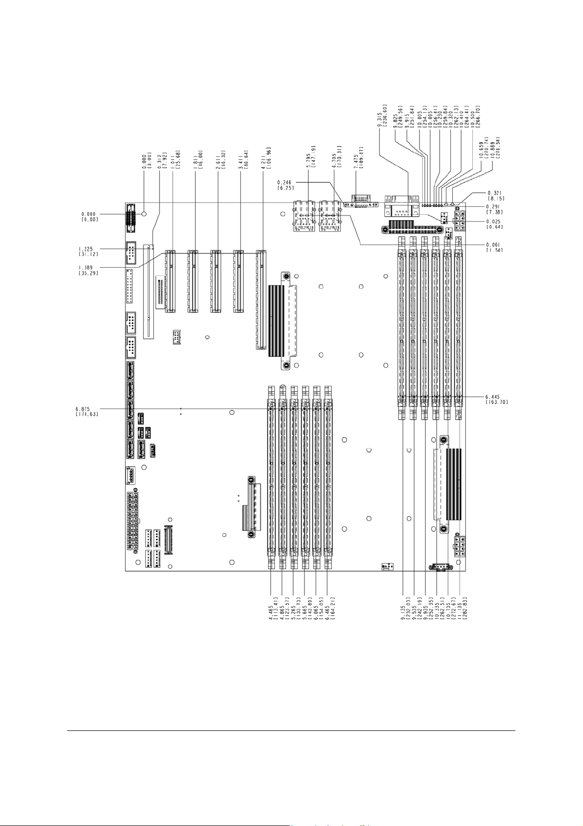
Figure 5. Major Connector Pin-1 Locations (1 of 2) ....................................................................... 9
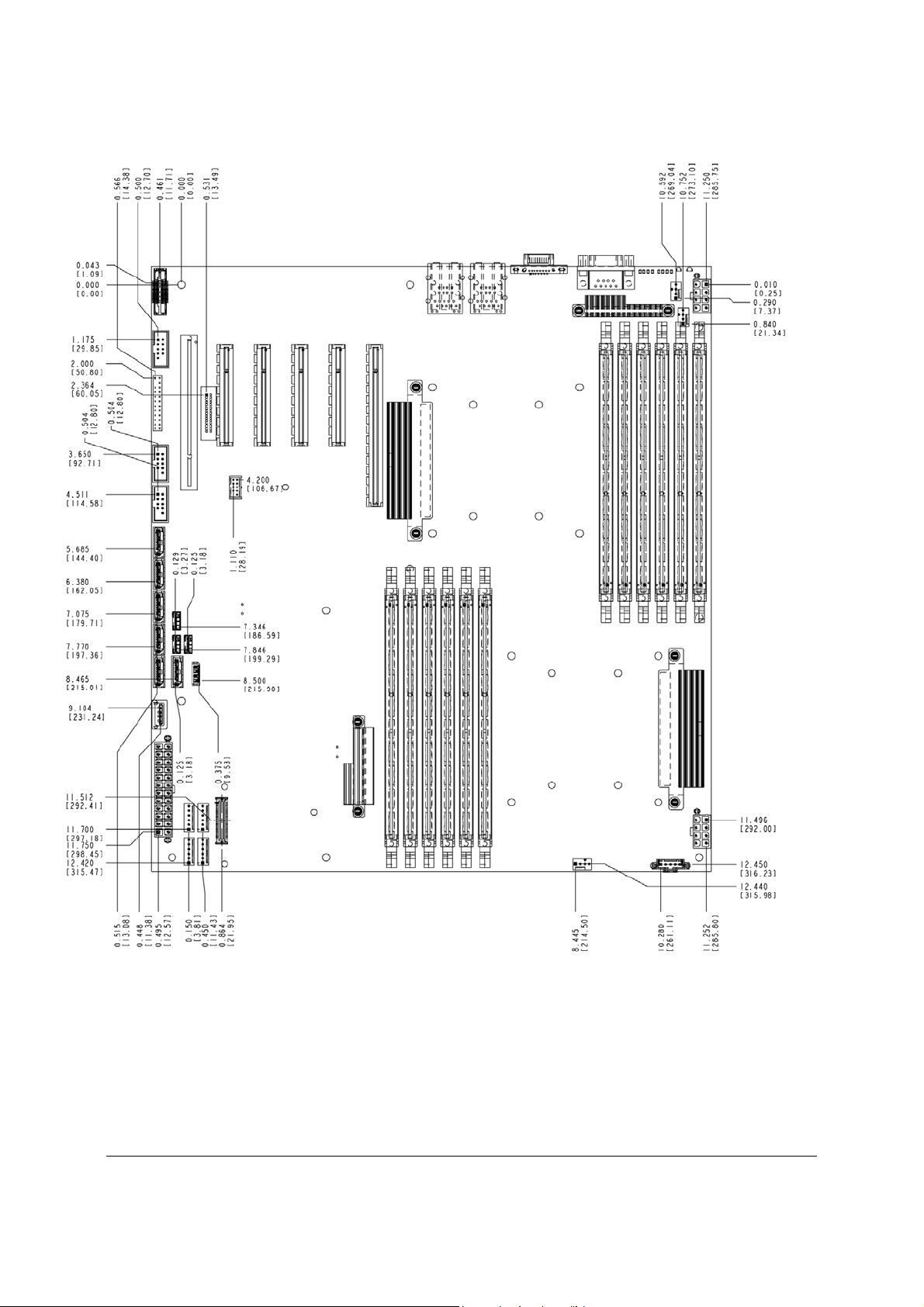
Figure 6. Major Connector Pin-1 Locations (2 of 2) ..................................................................... 10
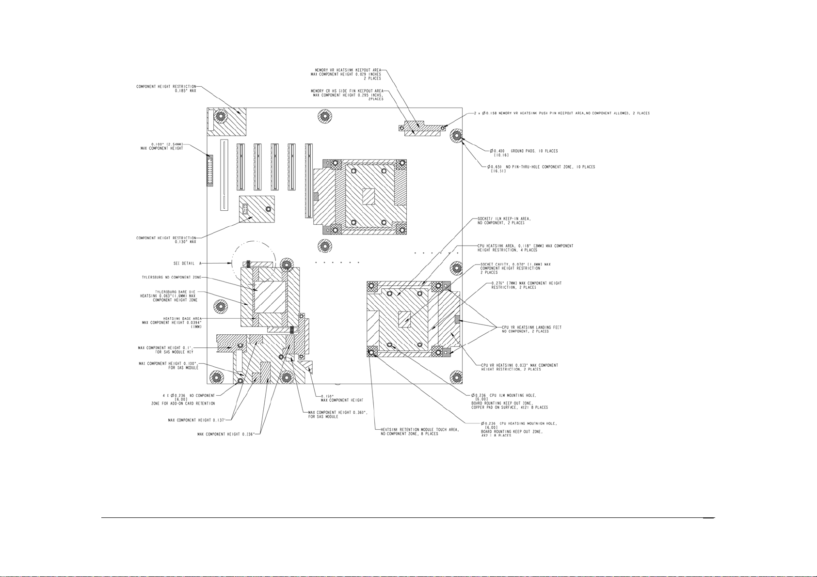
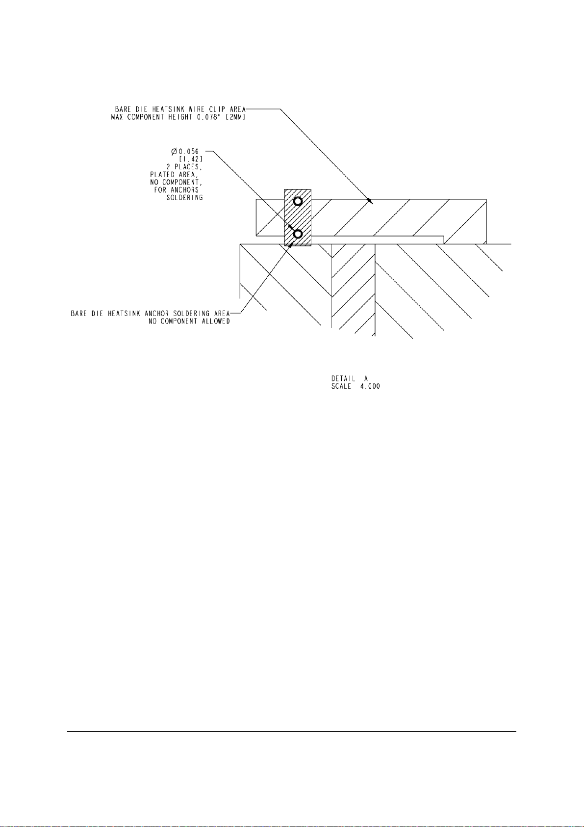
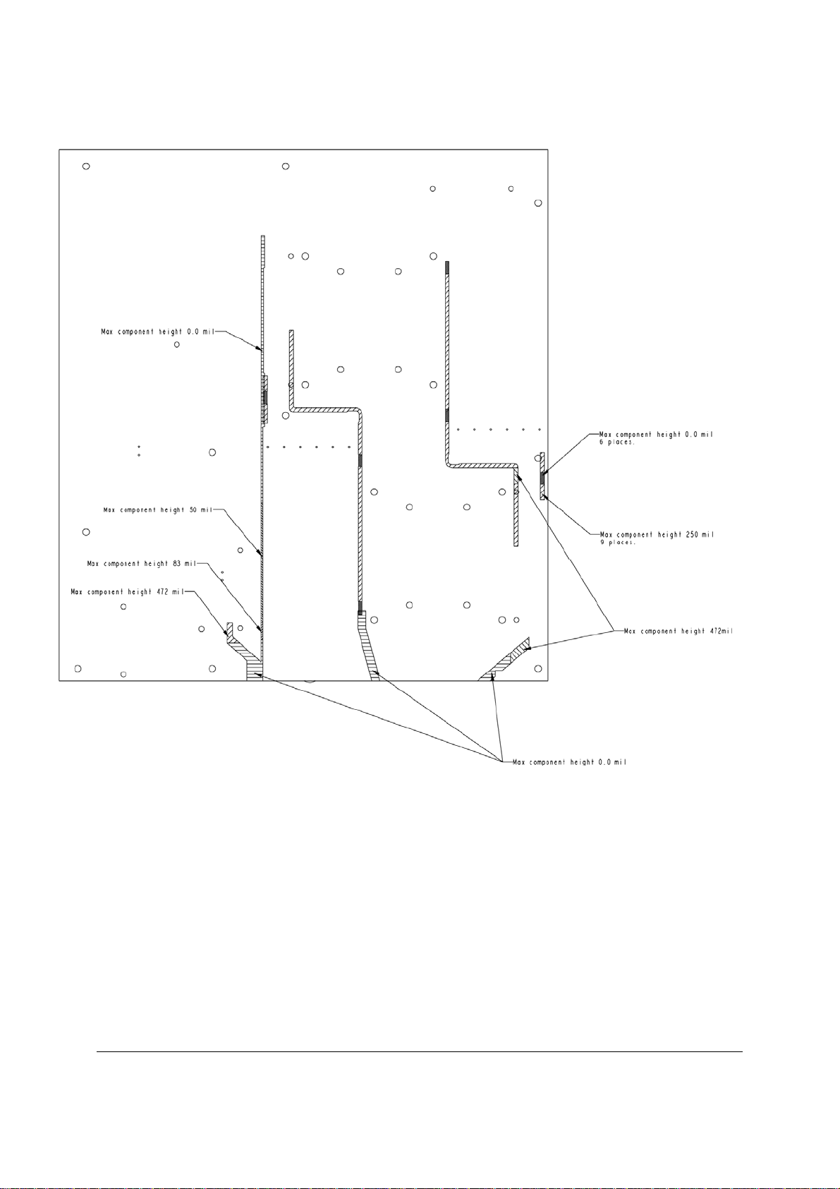
Figure 7. Primary Side Keep-out Zone (1 of 2) ............................................................................ 11
Figure 8. Primary Side Keep-out Zone (2 of 2) ............................................................................ 12
Figure 9. Primary Side Air Duct Keep-out Zone ........................................................................... 13
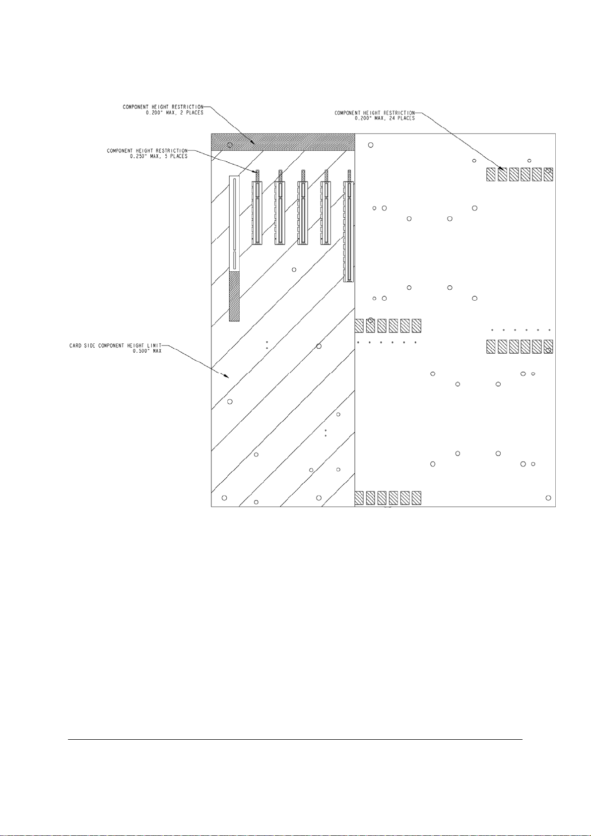
Figure 10. Primary Side Card-Side Keep-out Zone ..................................................................... 14
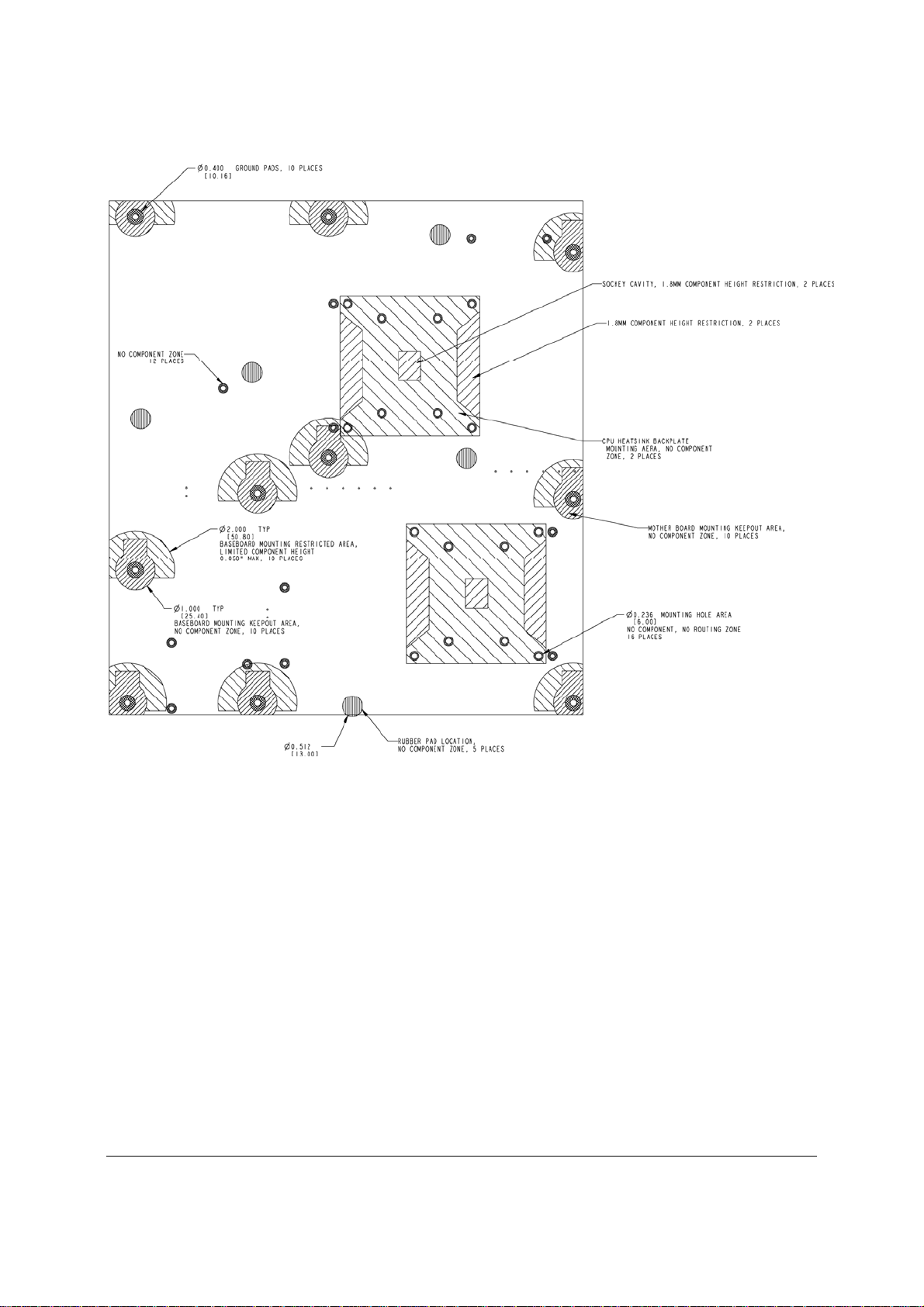
Figure 11. Second Side Keep-out Zone ....................................................................................... 15
Figure 12. Rear I/O Layout ........................................................................................................... 16
Figure 13. Intel
Figure 14. Intel
®
Server Board S5520HC Functional Block Diagram .......................................... 18
®
Server Board S5500HCV Functional Block Diagram ........................................ 19
Figure 15. Unified Retention System and Unified Back Plate Assembly ..................................... 26
Figure 16. Intel
Figure 17. Intel
Figure 18. Intel
Figure 19. Intel
®
Server Board S5520HC DIMM Slots Arrangement ........................................... 28
®
Server Board S5500HCV DIMM Slots Arrangement ........................................ 29
®
SAS Entry RAID Module AXX4SASMOD Component and Connector Layout 44
®
SAS Entry RAID Module AXX4SASMOD Functional Block Diagram............... 45
Figure 20. Integrated BMC Hardware .......................................................................................... 48
Figure 21. Setup Utility – TPM Configuration Screen .................................................................. 54
Figure 22. Setting Administrator password in BIOS ..................................................................... 56
Figure 23. Activating TPM ............................................................................................................ 57
Figure 24. TPM activated .............................................................................................................. 58
Figure 25. BIOS setting for TXT ................................................................................................... 59
Figure 26. Platform Control .......................................................................................................... 67
Figure 27. SMBUS Block Diagram ............................................................................................... 71
Figure 28. Setup Utility — Main Screen Display .......................................................................... 76
Figure 29. Setup Utility — Advanced Screen Display .................................................................. 78
Figure 30. Setup Utility — Processor Configuration Screen Display ........................................... 79
Figure 31. Setup Utility — Memory Configuration Screen Display .............................................. 82
Figure 32. Setup Utility — Configure RAS and Performance Screen Display ............................ 84
Figure 33. Setup Utility — Mass Storage Controller Configuration Screen Display .................... 85
Figure 34. Setup Utility — Serial Port Configuration Screen Display .......................................... 87
Figure 35. Setup Utility — USB Controller Configuration Screen Display ................................... 88
Figure 36. Setup Utility — PCI Configuration Screen Display ..................................................... 90
Figure 37. Setup Utility — System Acoustic and Performance Configuration Screen Display ... 91
Figure 38. Setup Utility — Security Configuration Screen Display .............................................. 92
Figure 39. Setup Utility — Server Management Configuration Screen Display .......................... 95
viii
Revision 1.8
Intel order number E39529-013
Page 9

Intel® Server Boards S5520HC, S5500HCV, and S5520HCT TPS List of Figures
Figure 40. Setup Utility — Console Redirection Screen Display ................................................. 96
Figure 41. Setup Utility — Server Management System Information Screen Display ................ 98
Figure 42. Setup Utility — Boot Options Screen Display ............................................................. 99
Figure 43. Setup Utility — Add New Boot Option Screen Display ............................................. 101
Figure 44. Setup Utility — Delete Boot Option Screen Display ................................................. 102
Figure 45. Setup Utility — Hard Disk Order Screen Display ...................................................... 102
Figure 46. Setup Utility — CDROM Order Screen Display ........................................................ 103
Figure 47. Setup Utility — Floppy Order Screen Display ........................................................... 103
Figure 48. Setup Utility — Network Device Order Screen Display ............................................ 104
Figure 49. Setup Utility — BEV Device Order Screen Display .................................................. 104
Figure 50. Setup Utility — Boot Manager Screen Display ......................................................... 105
Figure 51. Setup Utility — Error Manager Screen Display ........................................................ 106
Figure 52. Setup Utility — Exit Screen Display .......................................................................... 106
Figure 53. Jumper Blocks (J1E2, J1E4, J1E5, J1E6, J1H1) ..................................................... 118
Figure 54. 5-volt Stand-by Status LED Location ........................................................................ 122
Figure 55. Fan Fault LED’s Location .......................................................................................... 123
Figure 56. System Status LED Location .................................................................................... 124
Figure 57. DIMM Fault LED’s Location ...................................................................................... 126
Figure 58. POST Code Diagnostic LED Locations .................................................................... 127
Figure 59. Power Distribution Block Diagram ............................................................................ 130
Figure 60. Output Voltage Timing............................................................................................... 134
Figure 61. Turn On/Off Timing (Power Supply Signals) ............................................................ 135
Figure 62. Active Processor Heatsink Installation Requireme nt ................................................ 149
Figure 63. Diagnostic LED Placement Diagram ........................................................................ 161
Revision 1.8
Intel order number E39529-013
ix
Page 10

List of Tables Intel® Server Boards S5520HC, S5500HCV, and S5520HCT TPS
List of Tables
Table 1. IOH High-Level Summary .............................................................................................. 20
Table 2. Mixed Processor Configurations .................................................................................... 23
Table 3. Memory Running Frequency vs. Processor SKU .......................................................... 31
Table 4. Memory Running Frequency vs. Memory Population .................................................... 31
Table 5. Supported DIMM Population under the Dual Processors Configuration ....................... 37
Table 6. Supported DIMM Population under the Single Processor Configuration ...................... 37
Table 7. Onboard SATA Storage Mode Matrix ............................................................................ 40
Table 8. Intel
Table 9. Intel
Table 10. Intel
Table 11. PCI Riser Support ......................................................................................................... 43
Table 12. Intel
Table 13. Serial B Header Pin-out ................................................................................................ 49
Table 14. Video Modes ................................................................................................................. 50
Table 15. Onboard NIC Status LED ............................................................................................. 51
Table 16. TSetup Utility – Security Configuration Screen Fields ................................................. 54
Table 17. Basic and Advanced Management Features ............................................................... 63
Table 18. S5520HC, S5500HCV and S5520HCT Fan Domain Table ........................................ 69
Table 19. BIOS Setup Page Layout ............................................................................................. 73
Table 20. BIOS Setup: Keyboard Command Bar ........................................................................ 74
Table 21. Setup Utility — Main Screen Fields .............................................................................. 76
Table 22. Setup Utility — Advanced Screen Display Fields ........................................................ 78
Table 23. Setup Utility — Processor Configuration Screen Fields .............................................. 80
Table 24. Setup Utility — Memory Configuration Screen Fields ................................................. 83
Table 25. Setup Utility — Configure RAS and Performance Screen Fields ................................ 84
Table 26. Setup Utility — Mass Storage Controller Configuration Screen Fields ....................... 86
Table 27. Setup Utility — Serial Ports Configuration Screen Fields ............................................ 87
Table 28. Setup Utility — USB Controller Configuration Screen Fields ...................................... 89
Table 29. Setup Utility — PCI Configuration Screen Fields ......................................................... 90
Table 30. Setup Utility — System Acoustic and Performance Configuration Screen Fields ...... 92
Table 31. Setup Utility — Security Configuration Screen Fields ................................................. 93
Table 32. Setup Utility — Server Management Configuration Screen Fields ............................. 95
Table 33. Setup Utility — Console Redirection Configuration Fields .......................................... 97
Table 34. Setup Utility — Server Management System Information Fields ................................ 98
Table 35. Setup Utility — Boot Options Screen Fields .............................................................. 100
Table 36. Setup Utility — Add New Boot Option Fields ............................................................. 101
Table 37. Setup Utility — Delete Boot Option Fields ................................................................. 102
Table 38. Setup Utility — Hard Disk Order Fields ...................................................................... 102
®
Server Board S5520HC PCI Bus Segment Characteristics ................................. 42
®
Server Board S5500HCV PCI Bus Segment Characteristics .............................. 43
®
Server Board S5520HC PCI Riser Slot (Slot 6) ................................................. 43
®
SAS Entry RAID Module AXX4SASMOD Storage Mode .................................. 46
x
Revision 1.8
Intel order number E39529-013
Page 11

Intel® Server Boards S5520HC, S5500HCV, and S5520HCT TPS List of Tables
Table 39. Setup Utility — CDROM Order Fields ........................................................................ 103
Table 40. Setup Utility — Floppy Order Fields ........................................................................... 103
Table 41. Setup Utility — Network Device Order Fields ............................................................ 104
Table 42. Setup Utility — BEV Device Order Fields .................................................................. 105
Table 43. Setup Utility — Boot Manager Screen Fields ............................................................ 105
Table 44. Setup Utility — Error Manager Screen Fields ............................................................ 106
Table 45. Setup Utility — Exit Screen Fields ............................................................................. 107
Table 46. Board Connector Matrix ............................................................................................. 108
Table 47. Main Power Connector Pin-out (J1K3) ...................................................................... 109
Table 48. CPU 1 Power Connector Pin-out (J9A1) .................................................................... 109
Table 49. CPU 2 Power Connector Pin-out (J9K1) .................................................................... 110
Table 50. Power Supply Auxiliary Signal Connector Pin-out (J9K2) ......................................... 110
Table 51. Intel
®
RMM3 Connector Pin-out (J1C1) ..................................................................... 110
Table 52. LCP/IPMB Header Pin-out (J1G6) ............................................................................. 111
Table 53. HSBP Header Pin-out (J1F5, J1G3) .......................................................................... 111
Table 54. SGPIO Header Pin-out (J1G2) ................................................................................... 111
Table 55. Front Panel SSI Standard 24-pin Connector Pin-out (J1B3) ..................................... 112
Table 56. VGA Connector Pin-out (J7A1) .................................................................................. 112
Table 57. RJ-45 10/100/1000 NIC Connector Pin-out (J5A1, J6A1) ......................................... 113
Table 58. SATA/SAS Connector Pin-out (J1E3, J1G1, J1G4, J1G5, J1F1, J1F4) ................... 113
Table 59. SAS Module Slot Pin-out (J2J1) ................................................................................. 113
Table 60. External DB9 Serial A Port Pin-out (J8A1) ................................................................. 114
Table 61. Internal 9-pin Serial B Header Pin-out (J1B1) ........................................................... 114
Table 62. External USB Connector Pin-out (J5A1, J6A1) ......................................................... 115
Table 63. Internal USB Connector Pin-out (J1D1) ..................................................................... 115
Table 64. Internal USB Connector Pin-out (J1D2) ..................................................................... 115
Table 65. Pin-out of Internal Low-Profile USB Connector for Solid State Drive (J2D2) ............ 116
Table 66. Internal Type A USB Port Pin-out (J1H2) .................................................................. 116
Table 67. SSI 4-pin Fan Header Pin-out (J7K1, J9A2, J9A3) ................................................... 117
Table 68. SSI 6-pin Fan Header Pin-out (J1K1, J1K2, J1K4, J1K5) ......................................... 117
Table 69. Server Board Jumpers (J1E6, J1E2, J1E4, J1E5, J1H1) .......................................... 118
Table 70. System Status LED .................................................................................................... 125
Table 71. Server Board Design Specifications........................................................................... 128
Table 72. MTBF Estimate ........................................................................................................... 129
Table 73. Intel® Xeon
®
Processor Dual Processor TDP Guidelines .......................................... 131
Table 74. 670-W Load Ratings ................................................................................................... 131
Table 75. Voltage Regulation Limits ........................................................................................... 132
Table 76. Transient Load Requirements .................................................................................... 133
Table 77. Capacitive Loading Conditions ................................................................................... 133
Table 78. Ripple and Noise ........................................................................................................ 133
Table 79. Output Voltage Timing ................................................................................................ 134
Revision 1.8
Intel order number E39529-013
xi
Page 12

List of Tables Intel® Server Boards S5520HC, S5500HCV, and S5520HCT TPS
Table 80. Turn On/Off Timing ..................................................................................................... 135
Table 81. Compatible Chassis/Heatsink Matrix ......................................................................... 147
Table 82. Integrated BMC Core Sensors ................................................................................... 152
Table 83. Platform Specific BMC Features ................................................................................ 160
Table 84. POST Progress Code LED Example ......................................................................... 161
Table 85. POST Codes and Messages ...................................................................................... 162
Table 86. POST Error Messages and Handling ......................................................................... 166
Table 87. POST Error Beep Codes ............................................................................................ 169
Table 88. BMC Beep Codes ....................................................................................................... 169
xii
Revision 1.8
Intel order number E39529-013
Page 13

Intel® Server Boards S5520HC, S5500HCV, and S5520HCT TPS List of Tables
<This page intentionally left blank.>
Revision 1.8
Intel order number E39529-013
xiii
Page 14

Page 15

Intel® Server Boards S5520HC, S5500HCV, and S5520HCT TPS Introduction
1. Introduction
This Technical Product Specification (TPS) provides board-specific information detailing the
features, functionality, and high-level architecture of the Intel
®
Server Boards S5520HC,
S5500HCV and S5520HCT.
In addition, you can obtain design-level information for a given subsystem by ordering the
External Product Specifications (EPS) for the specific subsystem. EPS documents are not
publicly available and you must order them through your local Intel representative.
1.1 Chapter Outline
This document is divided into the following chapters:
Chapter 1 – Introduction
Chapter 2 – Overview
Chapter 3 – Functional Architecture
Chapter 4 – Platform Management
Chapter 5 – BIOS Setup Utility
Chapter 6 – Connector/Header Locations and Pin-outs
Chapter 7 – Jumper Blocks
Chapter 8 – Intel
Chapter 9 – Design and Environmental Specifications
Chapter 10 – Regulatory and Certification Information
Appendix A – Integration and Usage Tips
Appendix B – Compatible Intel
Appendix C – BMC Sensor Tables
Appendix D – Platform Specific BMC Appendix
Appendix E – POST Code Diagnostic LED Decoder
Appendix F – POST Error Messages and Handling
Appendix G – Installation Guidelines
Glossary
Reference Documents
®
Light Guided Diagnostics
®
Server Chassis
1.2 Server Board Use Disclaimer
Intel® Server Boards contain a number of high-density VLSI (Very-large-scale integration) and
power delivery components that require adequate airflow for cooling. Intel ensures through its
own chassis development and testing that when Intel
the fully integrated system meets the intended thermal requirements of these components. It is
the responsibility of the system integrator who chooses not to use Intel developed server
building blocks to consult vendor datasheets and operating parameters to determine the amount
of airflow required for their specific application and environmental conditions. Intel Corporation
cannot be held responsible if components fail or the server board does not operate correctly
when used outside any of the published operating or non-operating limits.
Revision 1.8
Intel order number E39529-013
®
server building blocks are used together,
1
Page 16

Overview Intel® Server Boards S5520HC, S5500HCV, and S5520HCT TPS
®
®
2. Overview
The Intel® Server Boards S5520HC, S5500HCV and S5520HCT are monolithic printed circuit
boards (PCBs) with features designed to support the pedestal server markets.
2.1 Intel
®
Server Boards S5520HC, S5500HCV and S5520HCT Feature Set
Feature Description
Processors
• Support for one or two Intel
Xeon® Processor(s) 5500 series up to 95W Thermal Design
Power
• Support for one or two Intel
®
Xeon® Processor(s) 5600 series up to 130W Thermal Design
Power
• 4.8 GT/s, 5.86 GT/s, and 6.4 GT/s Intel
• FC-LGA 1366 Socket B
Enterprise Voltage Regulator-Down (EVRD) 11.1
Memory
• Six memory channels (three channels for each processor socket)
Channels A, B, C, D, E, and F
• Support for 800/1066/1333 MT/s ECC Registered DDR3 Memory (RDIMM), ECC
Unbuffered DDR3 memory ((UDIMM)
• No support for mixing of RDIMMs and UDIMMs
®
Server Board S5520HC/S5520HCT:
12 DIMM slots
Two DIMM slots per channel
®
Server Board S5500HCV
Nine DIMM slots
Two DIMM slots on Channels A, B, and C
One DIMM slot on Channels D, E, and F
Server Board S5520HC/S5520HCT:
®
Intel
Intel
Intel
Intel
5520 Chipset
®
82801JIR I/O Controller Hub (ICH10R)
®
Server Board S5500HCV:
®
5500 Chipset
®
82801JIR I/O Controller Hub (ICH10R)
Chipset
• Intel
• Intel
• Intel
• Intel
Cooling Fan Support Support for
• Two processor fans (4-pin headers)
• Four front system fans (6-pin headers)
• One rear system fans (4-pin header)
• 3-pin fans are compatible with all fan headers
®
QuickPath Interconnect (Intel® QPI)
Revision 1.8
2
Intel order number E39529-013
Page 17

Intel® Server Boards S5520HC, S5500HCV, and S5520HCT TPS Overview
®
®
®
Feature Description
Add-in Card Slots
Hard Drive and
Optical Drive
Support
RAID Support
USB Drive Support
I/O control support
Video Support
LAN
Security**
• Intel
• Intel
• Optical devices are supported
• Six SATA connectors at 1.5 Gbps and 3 Gbps
• Four SAS connectors at 3 Gbps through optional Intel
• Intel
• Intel
• IT/IR RAID through optional Intel
• 4 ports full featured SAS/SATA hardware RAID through optional Intel
• One internal type A USB port with USB 2.0 support that supports a peripheral, such as a
• One internal low-profile USB port for USB Solid State Drive
• External connections:
• Internal connections:
• ServerEngines* LLC Pilot II* with 64 MB DDR2 memory, 8 MB allocated to graphics
• Two Gigabit through Intel
• Trusted Platform Module
Server Board S5520HC/S5520HCT: Six expansion slots
One full-length/full-height PCI Express* Gen2 slot (x16 Mechanically, x8 Electrically)
Three full-length/full-height PCI Express* Gen2 x8 slots
One full-length/full-height PCI Express* Gen1 slot (x8 Mechanically, x4 Electrically)
shared with SAS Module slot*.
One 32-bit/33 MHz PCI slot, keying for 5-V and Universal PCI add-in card
®
Server Board S5500HCV: Five expansion slots
One full-length/full-height PCI Express* Gen2 slot (x16 Mechanically, x4 Electrically)
Two full-length/full-height PCI Express* Express* Gen2 x8 slots
One full-length/full-height PCI Express* Gen1 slot (x8 Mechanically, x4 Electrically)
shared with SAS Module slot*.
One 32-bit/33 MHz PCI slot, keying for 5-volt and Universal PCI add-in card
®
SAS Entry RAID Module
AXX4SASMOD
Embedded Server RAID Technology II through onboard SATA connectors provides
SATA RAID 0, 1, and 10 with optional RAID 5 support provided by the Intel
®
RAID
Activation Key AXXRAKSW5
®
Embedded Server RAID Technology II through optional Intel® SAS Entry RAID
Module AXX4SASMOD provides SAS RAID 0, 1, and 10 with optional RAID 5 support
provided by the Intel
®
RAID Activation Key AXXRAKSW5
®
SAS Entry RAID Module AXX4SASMOD provides entry-
level hardware RAID 0, 1, 10/10E, and native SAS pass through mode
®
Integrated RAID
Module SROMBSASMR (AXXROMBSASMR), provides RAID 0, 1, 5, 6 and striping
capability for spans 10, 50, 60.
floppy drive
DB9 serial port A connection
One DH 10 serial port connector (optional)
Two RJ-45 NIC connectors for 10/100/1000 Mb connections: Dual GbE through the
®
82575EB Network Connection.
Intel
Four USB 2.0 ports at the back of the board
Two 9-pin USB headers, each supports two USB 2.0 ports
One DH10 serial port B header
Six SATA connectors at 1.5 Gbps and 3 Gbps
Four SAS connectors at 3 Gbps (optional)
One SSI-compliant 24-pin front control panel header
Integrated 2D video controller
Dual monitor video mode is supported
82575EB PHYs with Intel® I/O Acceleration Technology 2
support
Revision 1.8
3
Intel order number E39529-013
Page 18

Overview Intel® Server Boards S5520HC, S5500HCV, and S5520HCT TPS
®
Feature Description
Server Management
BIOS Flash
Form Factor
Compatible Intel®
Server Chassis
* The PCI Express* Gen 1 slot (x8 Mechanically, x4 Electrically) is not available when the SAS module slot is in use
and vice versa.
**The Trusted Platform Module is only availabe in S5520HCT
• Onboard ServerEngines* LLC Pilot II* Controller
Integrated Baseboard Management Controller (Integrated BMC), IPMI 2.0 compliant
Integrated Super I/O on LPC interface
• Support for Intel
®
• Intel
Light-Guided Diagnostics on field replaceable units
• Support for Intel
• Support for Intel
®
Remote Management Module 3
®
System Management Software 3.1 and beyond
®
Intelligent Power Node Manager (Need PMBus-compliant power supply)
• Winbond* W25X64
• SSI EEB (12”x13”)
• Intel
• Intel
• Intel
• Intel
• Intel
Server Chassis SC5650DP
®
Server Chassis SC5650BRP (PMBus-compliant Power Supply)
®
Server Chassis SC5600Base
®
Server Chassis SC5600BRP (PMBus-compliant Power Supply)
®
Server Chassis SC5600LX (PMBus-compliant Power Supply)
Revision 1.8
4
Intel order number E39529-013
Page 19
Intel® Server Boards S5520HC, S5500HCV, and S5520HCT TPS Overview
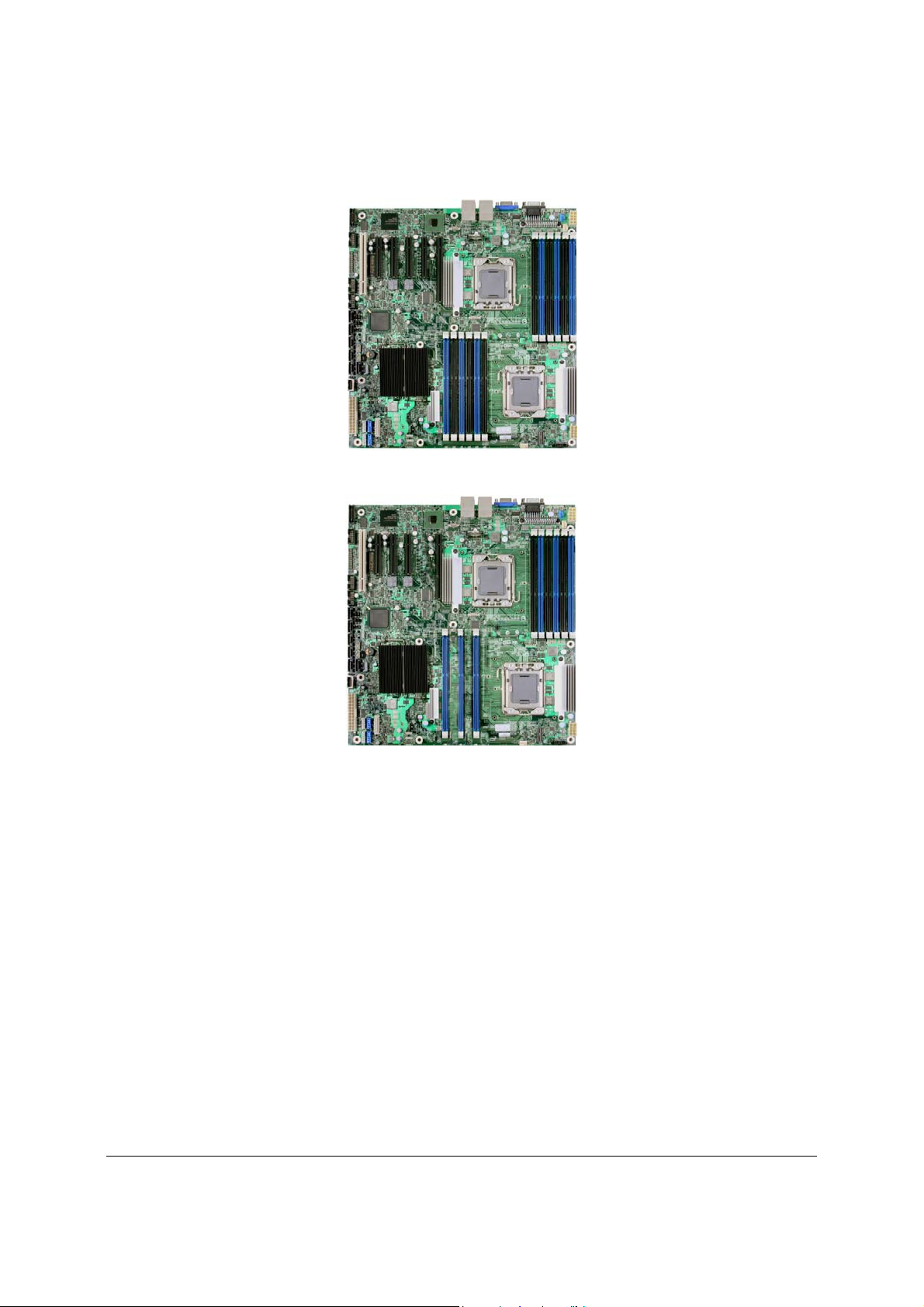
Server Board Layout
Figure 1. Intel® Server Board S5520HC
Figure 2. Intel® Server Board S5500HCV
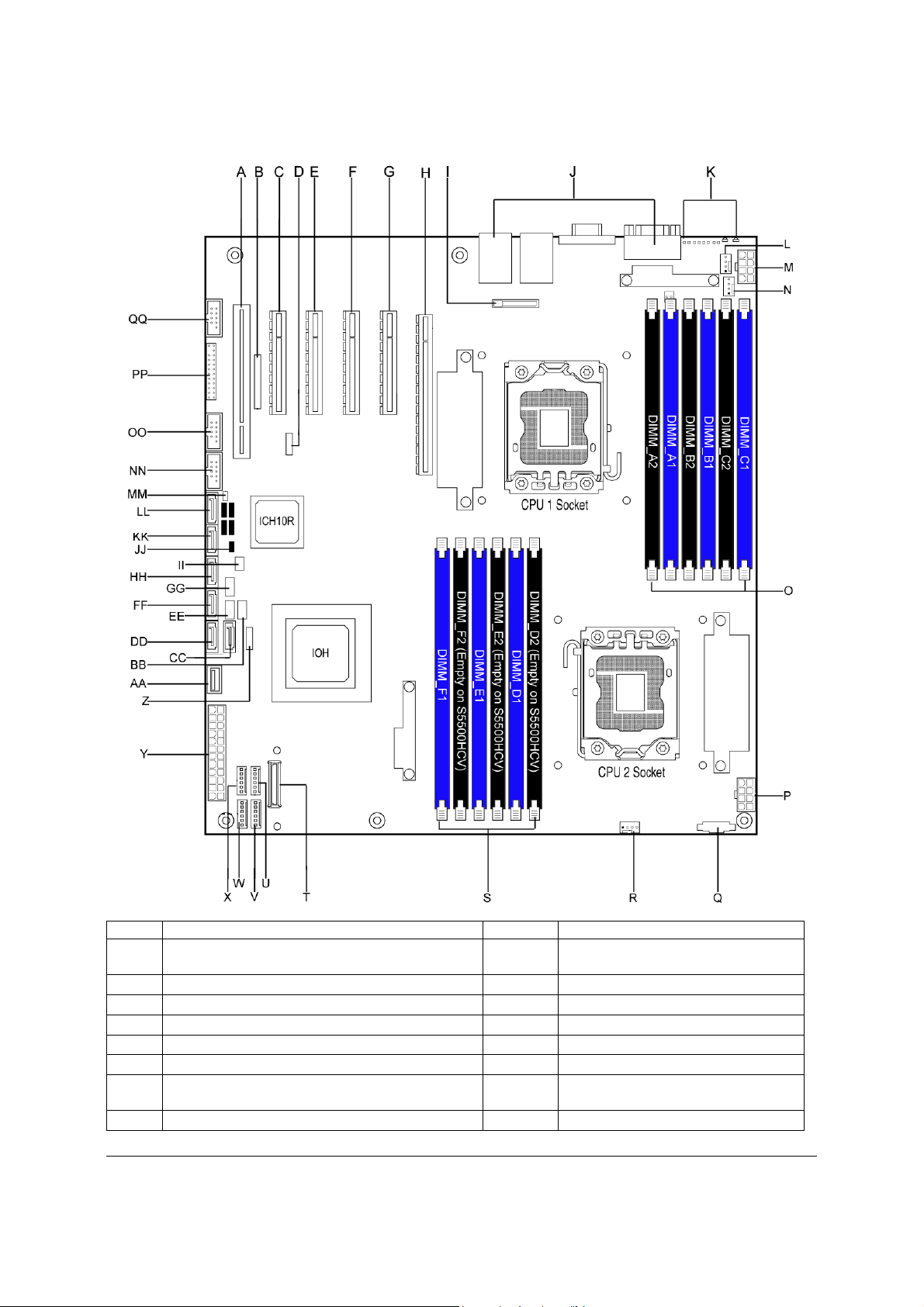
2.1.1 Server Board Connector and Component Layout
The following figure shows the layout of the server board. Each connector and major component
is identified by a number or letter, and a description is given below the figure.
Revision 1.8
Intel order number E39529-013
5
Page 20
Overview Intel® Server Boards S5520HC, S5500HCV, and S5520HCT TPS
®
Callout Description Callout Description
Slot 1, 32-bit/33 MHz PCI, Keying for 5V and
A
Universal
B Intel® RMM3 Slot X System Fan 1 Header (6-pin)
C Slot 2, PCI Express* x4 (x8 Mechanically) Y Main Power Connector
D Low-profile USB Solid State Drive Header Z LCP/IPMB Header
E Slot 3, PCI Express* Gen2 x8 AA Type A USB Port
F Slot 4, PCI Express* Gen2 x8 BB SATA SGPIO Header
Slot 5, PCI Express* Gen2 x8 (Empty on Intel
G
Server Board S5500HCV)
H
S5520HC: Slot 6, PCI Express* Gen2 x8 (x16
Revision 1.8
6
Intel order number E39529-013
W System Fan 2 Header (6-pin)
CC SATA Port 0
DD SATA Port 1
Page 21

Intel® Server Boards S5520HC, S5500HCV, and S5520HCT TPS Overview
Callout Description Callout Description
Mechanically)
S5500HCV: Slot 6, PCI Express* Gen2 x4 (x16
Mechanically)
I Battery EE HSBP_B
J Back Panel I/O Ports FF SATA Port 2
K Diagnostic and Identify LED’s GG HSBP_A
L System Fan 5 Header (4-pin) HH SATA Port 3
Power Connector for Processor 1 and Memory
M
attached to Processor 1
N Processor 1 Fan Header (4-pin) JJ Chassis Intrusion Header
O DIMM Sockets of Memory Channel A, B, and C KK SATA Port 4
Power Connector for Processor 2 and Memory
P
attached to Processor 2
Q Auxiliary Power Signal Connector MM
R Processor 2 Fan Header (4-pin) NN
S DIMM Sockets of Memory Channel D, E, and F OO USB Connector (9-pin)
T SAS Module Slot PP Front Control Panel header
U System Fan 3 Header (6-pin) QQ DH-10 Serial B header
V System Fan 4 Header (6-pin)
II SATA Software RAID 5 Key Header
LL SATA Port 5
HDD Activity LED Header (Connect to
Add-in Card HDD Activity LED
Header)
USB Connector (9-pin, for front panel
USB ports)
Figure 3. Major Board Components
Revision 1.8
7
Intel order number E39529-013
Page 22
Overview Intel® Server Boards S5520HC, S5500HCV, and S5520HCT TPS
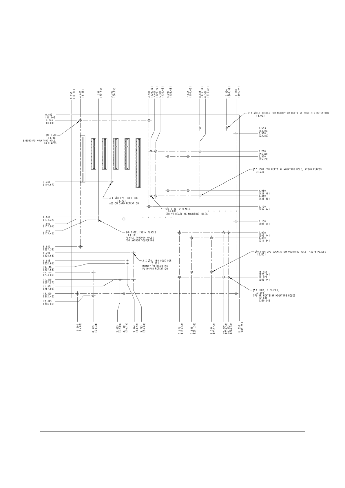
2.1.2 Server Board Mechanical Drawings
Figure 4. Mounting Hole Locations
Revision 1.8
8
Intel order number E39529-013
Page 23
Intel® Server Boards S5520HC, S5500HCV, and S5520HCT TPS Overview
Figure 5. Major Connector Pin-1 Locations (1 of 2)
Revision 1.8
Intel order number E39529-013
9
Page 24
Overview Intel® Server Boards S5520HC, S5500HCV, and S5520HCT TPS
Figure 6. Major Connector Pin-1 Locations (2 of 2)
Revision 1.8
10
Intel order number E39529-013
Page 25
Intel® Server Boards S5520HC, S5500HCV, and S5520HCT TPS Overview
Figure 7. Primary Side Keep-out Zone (1 of 2)
Revision 1.8
11
Intel order number E39529-013
Page 26
Overview Intel® Server Boards S5520HC, S5500HCV, and S5520HCT TPS
Figure 8. Primary Side Keep-out Zone (2 of 2)
Revision 1.8
12
Intel order number E39529-013
Page 27
Intel® Server Boards S5520HC, S5500HCV, and S5520HCT TPS Overview
Figure 9. Primary Side Air Duct Keep-out Zone
Revision 1.8
Intel order number E39529-013
13
Page 28
Overview Intel® Server Boards S5520HC, S5500HCV, and S5520HCT TPS
Figure 10. Primary Side Card-Side Keep-out Zone
Revision 1.8
14
Intel order number E39529-013
Page 29
Intel® Server Boards S5520HC, S5500HCV, and S5520HCT TPS Overview
Figure 11. Second Side Keep-out Zone
Revision 1.8
Intel order number E39529-013
15
Page 30
Overview Intel® Server Boards S5520HC, S5500HCV, and S5520HCT TPS
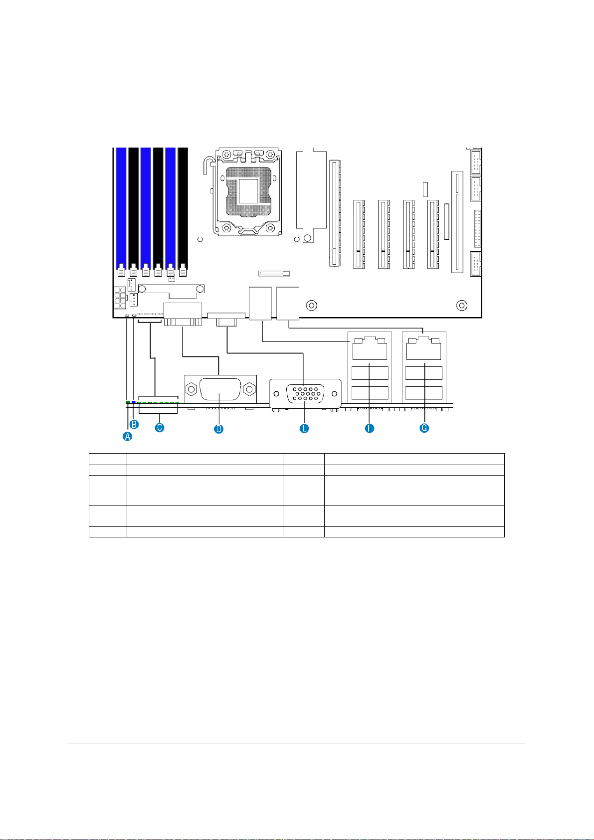
2.1.3 Server Board Rear I/O Layout
The following drawing shows the layout of the rear I/O components for the server boards.
Callout Description Callout Description
A System Status LED E Video
NIC Port 1 (1 Gb, Default Management
B ID LED F
C Diagnostics LED’s G
D Serial Port A
Port)
USB Port 2 (top), 3 (bottom)
NIC Port 2 (1 Gb)
USB Port 0 (top), 1 (bottom)
Figure 12. Rear I/O Layout
Revision 1.8
16
Intel order number E39529-013
Page 31

Intel® Server Boards S5520HC, S5500HCV, and S5520HCT TPS Functional Architecture
3. Functional Architecture
The architecture and design of the Intel® Server Boards S5520HC, S5500HCV and
S5520HCTis based on the Intel
systems based on the Intel
package with Intel
®
QuickPath Interconnect (Intel® QPI) speed at 6.40 GT/s, 5.86 GT/s, and
®
5520/5500 and ICH10R chipset. The chipset is designed for
®
Xeon® Processor 5500 Series in an FC-LGA 1366 Socket B
4.80 GT/s.
The chipset contains two main components:
– Intel
®
5520 I/O Hub or 5500 I/O Hub, which provides a connection point between
various I/O components and the Intel
®
QuickPath Interconnect (Intel® QPI) based
processors
– Intel
®
ICH10 RAID (ICH10R) I/O controller hub for the I/O subsystem
This chapter provides a high-level description of the functionality associated with each chipset
component and the architectural blocks that make up the server boards.
Revision 1.8
Intel order number E39529-013
17
Page 32

Functional Architecture Intel® Server Boards S5520HC, S5500HCV, and S5520HCT TPS
Figure 13. Intel® Server Board S5520HC Functional Block Diagram
Revision 1.8
18
Intel order number E39529-013
Page 33

Intel® Server Boards S5520HC, S5500HCV, and S5520HCT TPS Functional Architecture
Figure 14. Intel® Server Board S5500HCV Functional Block Diagram
Revision 1.8
Intel order number E39529-013
19
Page 34

Functional Architecture Intel® Server Boards S5520HC, S5500HCV, and S5520HCT TPS
3.1 Intel
The Intel® 5520 and 5500 I/O Hub (IOH) in the Intel® Server Boards S5520HC, S5500HCV and
S5520HCT provide a connection point between various I/O components and Intel
®
5520 and 5500 I/O Hub (IOH)
®
QPI-based
processors, which includes the following core platform functions:
®
• Intel
QPI link interface for the processor subsystem
• PCI Express* Ports
®
• Enterprise South Bridge Interface (ESI) for connecting Intel
ICH10R
• Manageability Engine (ME)
• Controller Link (CL)
• SMBus Interface
®
• Intel
The following table shows the high-level features of the Intel
Virtualization Technology for Directed I/O (Intel® VT-d)
®
5520 and 5500 IOH:
Table 1. IOH High-Level Summary
IOH SKU Intel® QPI Ports Supported Processor PCI Express*
Lanes
5520 2 Intel® Xeon® Processor 5500 Series 36 Intel® Intelligent Power Node
Manager
5500 2 Intel® Xeon® Processor 5500 Series 24 Intel® Intelligent Power Node
Manager
Manageability
3.1.1 Intel
The Intel® Server Boards S5520HC, S5500HCV and S5520HCT provide two full-width, cachecoherent, link-based Intel
connecting Intel
®
QuickPath Interconnect
®
®
QPI based processors. The two Intel® QPI link interfaces support full-width
QuickPath Interconnect interfaces from Intel® 5520 and 5500 IOH for
communication only and have the following main features:
z Packetized protocol with 18 data/protocol bits and 2 CRC bits per link per direction
Supporting 4.8 GT/s, 5.86 GT/s, and 6.4 GT/s
z Fully-coherent write cache with inbound write combining
z Read Current command support
z Support for 64-byte cache line size
3.1.2 PCI Express* Ports
The Intel® 5520 IOH is capable of interfacing with up to 36 PCI Express* Gen2 lanes, which
support devices with the following link width: x16, x8, x4, x2, and x1.
The Intel
support devices with the following link width: x16, x8, x4, x2, and x1.
All ports support PCI Express* Gen1 and Gen2 transfer rates.
For a detailed PCI Express* Slots definition in the Intel
and S5520HCT, see “3.5 PCI Subsystem.”
®
5500 IOH is capable of interfacing with up to 24 PCI Express* Gen2 lanes, which
®
Server Boards S5520HC, S5500HCV
Revision 1.8
20
Intel order number E39529-013
Page 35

Intel® Server Boards S5520HC, S5500HCV, and S5520HCT TPS Functional Architecture
3.1.3 Enterprise South Bridge Interface (ESI)
One x4 ESI link interface supporting PCI Express Gen1 (2.5 Gbps) transfer rate for connecting
®
Intel
ICH10R in the Intel® Server Boards S5520HC, S5500HCV and S5520HCT.
3.1.4 Manageability Engine (ME)
An embedded ARC controller is within the IOH providing the Intel® Server Platform Services
(SPS). The controller is also commonly referred to as the Manageability Engine (ME).
3.1.5 Controller Link (CL)
The Controller Link is a private, low-pin count (LPC), low power, communication interface
between the IOH and the ICH10 portions of the Manageability Engine subsystem.
Revision 1.8
Intel order number E39529-013
21
Page 36

Functional Architecture Intel® Server Boards S5520HC, S5500HCV, and S5520HCT TPS
3.2 Processor Support
The Intel® Server Boards S5520HC, S5500HCV and S5520HCT support the following
processors:
®
• One or two Intel
GT/s Intel
®
• One or two Intel
interface and Thermal Design Power (TDP) up to 130 W.
Xeon® Processor 5500 Series with a 4.8 GT/s, 5.86 GT/s, or 6.4
QPI link interface and Thermal Design Power (TDP) up to 95 W.
®
Xeon® Processor 5600 Series with a 6.4 GT/s Intel® QPI link
The server boards do not support previous generations of the Intel
®
Xeon® Processors.
For a complete updated list of supported processors, see:
http://support.intel.com/support/motherboards/server/S5520HC/
. On the Support tab, look for
“Compatibility” and then “Supported Processor List”.
3.2.1 Processor Population Rules
You must populate processors in sequential order. Therefore, you must populate Processor
socket 1 (CPU 1) before processor socket 2 (CPU 2).
When only one processor is installed, it must be in the socket labeled CPU1, which is located
near the rear edge of the server board. When a single processor is installed, no terminator is
required in the second processor socket.
For optimum performance, when two processors are installed, both must be the identical
revision and have the same core voltage and Intel
®
QPI/core speed.
3.2.2 Mixed Processor Configurations.
The following table describes mixed processor conditions and recommended actions for the
®
Intel
Server Boards S5520HC, S5500HCV and S5520HCT. Errors fall into one of three
categories:
z Halt: If the system can boot, it pauses at a blank screen with the text
“Unrecoverable fatal error found. System will not boot until the error is resolved” and
“Press <F2> to enter setup”, regardless of if the “Post Error Pause” setup option is
enabled or disabled. After entering setup, the error message displays on the Error
Manager screen, and an error is logged to the System Event Log (SEL) with the
error code. The system cannot boot unless the error is resolved. The user needs to
replace the faulty part and restart the system.
z Pause: If the “Post Error Pause” setup option is enabled, the system goes directly to
the Error Manager screen to display the error and log the error code to SEL.
Otherwise, the system continues to boot and no prompt is given for the error,
although the error code is logged to the Error Manager and in a SEL message.
z Minor: The message is displayed on the screen or on the Error Manager screen.
The system continues booting in a degraded state regardless of if the “Post Error
Pause” setup option is enabled or disabled. The user may want to replace the
erroneous unit.
Revision 1.8
22
Intel order number E39529-013
Page 37

Intel® Server Boards S5520HC, S5500HCV, and S5520HCT TPS Functional Architecture
Table 2. Mixed Processor Configurations
Error Severity System Action
Processor family not
identical
Processor stepping
mismatch
Processor cache not
identical
Processor frequency
(speed) not identical
Halt The BIOS detects the error condition and responds as follows:
– Logs the error into the system event log (SEL).
– Alerts the Integrated BMC about the configuration error.
– Does not disable the processor.
– Displays “0194: Processor 0x family mismatch detected” message in
the Error Manager.
– Halts the system and will not boot until the fault condition is
remedied.
Pause The BIOS detects the stepping difference and responds as follows:
– Checks to see whether the steppings are compatible – typically +/-
one stepping.
– If so, no error is generated (this is not an error condition).
– Continues to boot the system successfully.
Otherwise, this is a stepping mismatch error, and the BIOS responds as
follows:
– Displays “0193: Processor 0x stepping mismatch” message in the
Error Manager and logs it into the SEL.
– Takes Minor Error action and continues to boot the system.
Halt The BIOS detects the error condition and responds as follows:
– Logs the error into the SEL.
– Alerts the Integrated BMC about the configuration error.
– Does not disable the processor.
– Displays “0192: Processor 0x cache size mismatch detected”
message in the Error Manager.
– Halts the system and will not boot until the fault condition is
remedied.
Halt The BIOS detects the error condition and responds as follows:
– Adjusts all processor frequencies to the highest common frequency.
– No error is generated – this is not an error condition.
– Continues to boot the system successfully.
If the frequencies for all processors cannot be adjusted to be the same,
then the BIOS:
– Logs the error into the SEL.
– Displays “0197: Processor 0x family is not supported” message in the
Error Manager.
– Halts the system and will not boot until the fault condition is
remedied.
Revision 1.8
23
Intel order number E39529-013
Page 38

Functional Architecture Intel® Server Boards S5520HC, S5500HCV, and S5520HCT TPS
Error Severity System Action
Processor Intel®
QuickPath
Interconnect speeds
not identical
Processor microcode
missing
Halt The BIOS detects the error condition and responds as follows:
– Adjusts all processor QPI frequencies to highest common frequency.
– No error is generated – this is not an error condition
– Continues to boot the system successfully.
If the link speeds for all QPI links cannot be adjusted to be the same, then
the BIOS:
– Logs the error into the SEL.
– Displays “0195: Processor 0x Intel
in the Error Manager.
– Halts the system and will not boot until the fault condition is
remedied.
Minor The BIOS detects the error condition and responds as follows:
– Logs the error into the SEL.
– Does not disable the processor.
– Displays “8180: Processor 0x microcode update not found” message
in the Error Manager or on the screen.
– The system continues to boot in a degraded state, regardless of the
setting of POST Error Pause in Setup.
®
QPI speed mismatch” message
3.2.3 Intel
®
Hyper-Threading Technology (Intel® HT)
If the installed processor supports the Intel® Hyper-Threading Technology, the BIOS Setup
provides an option to enable or disable this feature. The default is enabled.
The BIOS creates additional entries in the ACPI MP tables to describe the virtual processors.
The SMBIOS Type 4 structure shows only the installed physical processors. It does not
describe the virtual processors.
Because some operating systems are not able to efficiently use the Intel
®
HT Technology, the
BIOS does not create entries in the Multi-Processor Specification, Version 1.4 tables to describe
the virtual processors.
3.2.4 Enhanced Intel SpeedStep
®
Technology (EIST)
If the installed processor supports the Enhanced Intel SpeedStep® Technology, the BIOS Setup
provides an option to enable or disable this feature. The Default is enabled.
3.2.5 Intel
®
Turbo Boost Technology
Intel® Turbo Boost Technology opportunistically and automatically allows the processor to run
faster than the marked frequency if the part is operating below power, temperature, and current
limits.
If the processor supports this feature, the BIOS setup provides an option to enable or disable
this feature. The default is enabled.
3.2.6 Execute Disable Bit Feature
The Execute Disable Bit feature (XD bit) can prevent data pages from being used by malicious
software to execute code. A processor with the XD bit feature can provide memory protection in
one of the following modes:
z Legacy protected mode if Physical Address Extension (PAE) is enabled.
Revision 1.8
24
Intel order number E39529-013
Page 39

Intel® Server Boards S5520HC, S5500HCV, and S5520HCT TPS Functional Architecture
z Intel
®
64 mode when 64-bit extension technology is enabled (Entering Intel® 64
mode requires enabling PAE).
You can enable and disable the XD bit in the BIOS Setup. The default behavior is enabled.
3.2.7 Core Multi-Processing
The BIOS setup provides the ability to selectively enable one or more cores. The default
behavior is to enable all cores. You can do this through the BIOS setup option for active core
count.
The BIOS creates entries in the Multi-Processor Specification, Version 1.4 tables to describe
multi-core processors.
3.2.8 Direct Cache Access (DCA)
Direct Cache Access (DCA) is a system-level protocol in a multi-processor system to improve
I/O network performance, thereby providing higher system performance. The basic idea is to
minimize cache misses when a demand read is executed. This is accomplished by placing the
data from the I/O devices directly into the processor cache through hints to the processor to
perform a data pre-fetch and install it in its local caches.
The BIOS setup provides an option to enable or disable this feature. The default behavior is
enabled.
3.2.9 Unified Retention System Support
The server boards comply with Unified Retention System (URS) and Unified Backplate
Assembly. The server boards ship with Unified Backplate Assembly at each processor socket.
The URS retention transfers load to the server boards via the Unified Backplate Assembly. The
URS spring, captive in the heatsink, provides the necessary compressive load for the thermal
interface material (TIM). All components of the URS heatsink solution are captive to the
heatsink and only require a Phillips* screwdriver to attach to the Unified Backplate Assembly.
See the following figure for the stacking order of URS components.
The Unified Backplate Assembly is removable, allowing for the use of non-Intel
retention solutions.
®
heatsink
Revision 1.8
Intel order number E39529-013
25
Page 40

Functional Architecture Intel® Server Boards S5520HC, S5500HCV, and S5520HCT TPS
Figure 15. Unified Retention System and Unified Back Plate Assembly
Revision 1.8
26
Intel order number E39529-013
Page 41

Intel® Server Boards S5520HC, S5500HCV, and S5520HCT TPS Functional Architecture
3.3 Memory Subsystem
The Intel® Xeon® Processor 5500 Series on the Intel® Server Boards S5520HC, S5500HCV and
S5520HCT are populated on CPU sockets. Each processor installed on the CPU socket has an
integrated memory controller (IMC), which supports up to three DDR3 channels and groups
DIMMs on the server boards into autonomous memory.
3.3.1 Memory Subsystem Nomenclature
The nomenclature for DIMM sockets implemented in the Intel® Server Boards S5520HC,
S5500HCV and S5520HCT is represented in the following figures.
z DIMMs are organized into physical slots on DDR3 memory channels that belong to
processor sockets.
z The memory channels for CPU 1 socket are identified as Channels A, B, and C. The
memory channels for CPU 2 socket are identified as Channels D, E, and F.
z The DIMM identifiers on the silkscreen on the board provide information about which
channel/CPU Socket they belong to. For example, DIMM_A1 is the first slot on
Channel A of CPU 1 socket. DIMM_D1 is the first slot on Channel D of CPU 2
Socket.
z Processor sockets are self-contained and autonomous. However, all configurations
in the BIOS setup, such as RAS, Error Management, and so forth, are applied
commonly across sockets.
The Intel
processor) with two DIMM slots per channel, thus supporting up to twelve DIMMs in twoprocessor configuration. See Figure 16 for the Intel
arrangement.
®
Server Board S5520HC supports six DDR3 memory channels (three channels per
®
Server Board S5520HC DIMM slots
The Intel
®
Server Board S5500HCV supports six DDR3 memory channels (three channels per
processor) with two DIMM slots per channel at Channels A, B, and C, and one DIMM slot per
channel at Channels D, E, and F, thereby supporting up to nine DIMMs in a two-processor
configuration. See Figure 17 for the Intel
Revision 1.8
®
Server Board S5500HCV DIMM slots arrangement.
Intel order number E39529-013
27
Page 42

Functional Architecture Intel® Server Boards S5520HC, S5500HCV, and S5520HCT TPS
Server Board CPU Socket DIMM Identifier Channel/Slot
Intel® Server Board S5520HC
Figure 16. Intel® Server Board S5520HC DIMM Slots Arrangement
CPU 1
CPU 2
A1 (Blue) Channel A, Slot 0
A2 (Black) Channel A, Slot 1
B1 (Blue) Channel B, Slot 0
B2 (Black) Channel B, Slot 1
C1 (Blue) Channel C, Slot 0
C2 (Black) Channel C, Slot 1
D1 (Blue) Channel D, Slot 0
D2 (Black) Channel D, Slot 1
E1 (Blue) Channel E, Slot 0
E2 (Black) Channel E, Slot 1
F1 (Blue) Channel F, Slot 0
F2 (Black) Channel F, Slot 1
Revision 1.8
28
Intel order number E39529-013
Page 43

Intel® Server Boards S5520HC, S5500HCV, and S5520HCT TPS Functional Architecture
Server Board
CPU 1
Intel® Server Board
S5500HCV
CPU 2
Figure 17. Intel® Server Board S5500HCV DIMM Slots Arrangement
3.3.2 Supported Memory
z Both Intel
1.5-V DDR3 DIMMs.
Intel
Inte
z Both Intel
Registered DDR3 DIMMs (RDIMMs), and ECC Unbuffered DDR3 DIMMs (UDIMMs).
®
Server Board S5520HC and Intel® Server Board S5500HCV support
®
Server Board S5520HC supports up to 12 DIMMs with a maximum of
192GB memory capacity.
l®
Server Board S5500HCV supports up to 9 DIMMs with a maximum of
144GB memory capacity.
®
Server Board S5520HC and Intel® Server Board S5500HCV support
CPU Socket
DIMM Identifier
A1 (Blue) Channel A, Slot 0
A2 (Black) Channel A, Slot 1
B1 (Blue) Channel B, Slot 0
B2 (Black) Channel B, Slot 1
C1 (Blue) Channel C, Slot 0
C2 (Black) Channel C, Slot 1
D1 (Blue) Channel D, Slot 0
E1 (Blue) Channel E, Slot 0
F1 (Blue) Channel F, Slot 0
Channel/Slot
Revision 1.8
29
Intel order number E39529-013
Page 44

Functional Architecture Intel® Server Boards S5520HC, S5500HCV, and S5520HCT TPS
Mixing of RDIMMs and UDIMMs is not supported.
Mixing memory type, size, speed and/or rank on this platform has not been
validated and is not supported
Mixing memory vendors is not supported on this platform by Intel
Non-ECC memory is not supported and has not been validated in a server
environment
z Both Intel
®
Server Board S5520HC and Intel® Server Board S5500HCV support the
following DIMM and DRAM technologies:
RDIMMs:
– Single-, Dual-, and Quad-Rank
– x 4 or x8 DRAM with 1 Gb and 2 Gb technology, no support for 2 Gb
DRAM based 2 GB or 4 GB RDIMMs
– DDR3 1333 (Single- and Dual-Rank only), DDR3 1066, and DDR3 800
UDIMMs:
– Single- and Dual-Rank
– x8 DRAM with 1 Gb or 2 Gb technology
– DDR3 1333, DDR3 1066, and DDR3 800
3.3.3 Processor Cores, QPI Links and DDR3 Channels Frequency Configuration
The Intel® Xeon® 5500 series processor connects to other Intel® Xeon® 5500 series processors
and Intel
cores and the QPI links of Intel
There are no gear-ratio requirements for the Intel
®
5500/5520 IOH through the Intel® QPI link interface. The frequencies of the processor
®
Xeon® 5500 series processor are independent from each other.
®
Xeon® Processor 5500 Series.
®
Intel
5500/5520 IOH supports 4.8 GT/s, 5.86 GT/s, and 6.4 GT/s frequencies for the QPI links.
During QPI initialization, the BIOS configures both endpoints of each QPI link to the same
supportable speeds for the correct operation.
During memory discovery, the BIOS arrives at a fastest common frequency that matches the
requirements of all components of the memory system and then configures the DDR3 DIMMs
for the fastest common frequency.
In addition, rules on the following tables (Tables 3 and 4) also decide the global common
memory system frequency.
Revision 1.8
30
Intel order number E39529-013
Page 45

Intel® Server Boards S5520HC, S5500HCV, and S5520HCT TPS Functional Architecture
o
z
Y
e
e
e
o
Table 3. Memory Running Frequency vs. Processor SKU
DIMM Type
Memory Running Frequency
(Hz) = Fastest Common
Frequency of Processor
IMC and Memory
Processor Integrated
Memory Controller
(IMC) Max.
Frequency (Hz)
800 800 800 800
1066 800 1066 1066
1333 800 1066 1333
DDR3 800 DDR3 1066 DDR3 1333
Table 4. Memory Running Frequency vs. Memory Population
DIMM
DIMM Type
RDIMM 1 Y Y Y 1N SR or DR
RDIMM 1 Y
RDIMM 2 Y Y N 1N SR or DR
RDIMM 2 Y N N 1N QR only
UDIMM
w/ or w/o
ECC
UDIMM
w/ or w/o
ECC
1N: One clock cycle for the DRAM commands arrive at the DIMMs to execute.
2N: Two clock cycles for the DRAM commands arrive at the DIMMs to execute.
Populated
Per Channel
1 Y Y Y 1N SR or DR
2 Y Y N 2N SR or DR
Memory Running Frequency
(Y/N)
800MHz 1066MHz 1333MHz
N 1N QR only
Command/
Address
Rate
Ranks Per DIMM
SR: Single-Rank
DR: Dual-Rank
QR: Quad-Rank
Description
All RDIMMs run at the fastest
common frequency of process
IMCs and installed memory:
800MHz, 1066MHz, or 133MH
All RDIMMs run at 800MHz or
1066MHz when Quad-Rank
RDIMM is installed in any
channel.
All RDIMMs run at 800MHz or
1066MHz when two RDIMMs
(Single-Rank or Dual-Rank) ar
installed in the same channel.
All RDIMMs run at 800MHz wh
two RDIMMs (either or both ar
Quad-Rank RDIMMs) are
installed in the same channel.
All UDIMMs run at the fastest
common frequency of process
IMCs and installed memory:
800MHz, 1066MHz, or
1333MHz.
All UDIMMs run at 800MHz or
1066MHz when two UDIMMs
(Single- or Dual-Rank) are
installed in the same channel.
Revision 1.8
31
Intel order number E39529-013
Page 46

Functional Architecture Intel® Server Boards S5520HC, S5500HCV, and S5520HCT TPS
3.3.4 Publishing System Memory
z The BIOS displays the “Total Memory” of the system during POST if the “Quiet
Boot” is disabled in the BIOS Setup. This is the total size of memory discovered by
the BIOS during POST, and is the sum of the individual sizes of installed DDR3
DIMMs in the system.
z The BIOS also provides the total memory of the system in the BIOS setup (Main
page and Advanced | Memory Configuration Page). This total is the same as the
amount described by the previous bullet.
z The BIOS displays the “Ef fective Memory” of the system in the BIOS Setup
(Advanced | Memory Configuration Page). The term Effective Memory refers to the
total size of all active DDR3 DIMMs (not disabled) and not being used as redundant
units in Mirrored Channel Mode.
z If Quiet Boot is disabled, the BIOS displays the total system memory on the
diagnostic screen at the end of POST. This total is the same as the amount
described by the first bullet.
3.3.4.1 Memory Reservation for Memory-mapped Functions
A region of size of 40 MB of memory below 4 GB is always reserved for mapping chipset,
processor, and BIOS (flash) spaces as memory-mapped I/O regions. This region appears as a
loss of memory to the operating system.
This (and other) reserved regions are reclaimed by the operating system if PAE is enabled in
the operating system.
In addition to this memory reservation, the BIOS creates another reserved region for memorymapped PCI Express* functions, including a standard 64 MB or 256 MB of standard PCI
Express* MMIO configuration space. This is based on the setup selection, “Maximize Memory
below 4GB”.
If this is set to “Enabled”, the BIOS maximizes usage of memory below 4 GB, for an operating
system without PAE capability, by limiting PCI Express* Extended Configuration Space to 64
buses, rather than the standard 256 buses.
3.3.4.2 High-Memory Reclaim
When 4 GB or more of physical memory is installed (physical memory is the memory installed
as DDR3 DIMMs), the reserved memory is lost. However, the Intel
®
5500/5520 I/O Hub provides
a feature called high-memory reclaim, which allows the BIOS and the operating system to
remap the lost physical memory into system memory above 4 GB (the system memory is the
memory the processor can see).
The BIOS always enables high-memory reclaim if it discovers installed physical memory equal
to or greater than 4 GB. For the operating system, you can recover the reclaimed memory only
if the PAE feature in the processor is supported and enabled. Most operating systems support
this feature. For details, see your operating system’s relevant manuals.
3.3.5 Memory Interleaving
The Intel® Xeon® Processor 5500 Series supports the following memory interleaving mode:
Revision 1.8
32
Intel order number E39529-013
Page 47

Intel® Server Boards S5520HC, S5500HCV, and S5520HCT TPS Functional Architecture
• Bank Interleaving – Interleave cache-line data between participant ranks.
• Channel Interleaving – Interleave between channel when not in Mirrored Channel Mode.
• Socket Interleaving – Interleaved memory can spread between both CPU sockets when
NUMA mode is disabled, given both CPU sockets are populated and DDR3 DIMMs are
installed in slots for both sockets.
3.3.6 Memory Test
3.3.6.1 Integrated Memory BIST Engine
The Intel
®
Xeon® Processor 5500 series incorporate an integrated Memory Built-in Self Test
(BIST) engine enabled to provide extensive coverage of memory errors at both the memory
cells and the data paths emanating from the DDR3 DIMMs.
The BIOS also uses the Memory BIST to initialize memory at the end of the memory discovery
process.
3.3.7 Memory Scrub Engine
The Intel® Xeon® Processor 5500 Series incorporates a memory scrub engine, which performs
periodic checks on the memory cells, and identifies and corrects single-bit errors. Two types of
scrubbing operations are supported:
• Demand scrubbing – Executes when an error is encountered during normal read/write
of data.
• Patrol scrubbing – Proactively walks through populated memory space seeking soft
errors.
The BIOS enables both demand scrubbing and patrol scrubbing by default.
Demand scrubbing is not possible when memory mirroring is enabled. Therefore, if the memory
is configured for mirroring, the BIOS disables it automatically.
3.3.8 Memory RAS
3.3.8.1 RAS Features
The Intel
channel modes:
These channel modes are used in conjunction with the standard Memory Test (Built-in Self-Test
(BIST) and Memory Scrub engines to provide full RAS support.
Channel RAS feature are supported only if both CPU sockets are populated and support the
right population. For more information, refer to Section 3.3.9.
®
Server Boards S5520HC, S5500HCV and S5520HCT support the following memory
• Independent Channel Mode
• Mirrored Channel Mode – providing Channel RAS feature
Revision 1.8
Intel order number E39529-013
33
Page 48

Functional Architecture Intel® Server Boards S5520HC, S5500HCV, and S5520HCT TPS
3.3.8.2 Independent Channel Mode
In the Independent Channel mode, you can populate multiple channels on any channel in any
order. The Independent Channel mode provides less RAS capability but better DIMM isolation
in case of errors. Moreover, it allows the best interleave mode possible and thereby increases
performance and thermal characteristics.
Adjacent slots on a DDR3 Channel from the Intel
®
Xeon® Processor 5500 series do not need
matching size and organization in independent channel mode. However, the speed of the
channel is configured to the maximum common speed of the DIMMs.
The Single Channel mode is established using the Independent Channel mode by populating
the DIMM slots from Channel A.
3.3.8.3 Mirrored Channel Mode
The Mirrored Channel mode is a RAS feature in which two identical images of memory channel
data are maintained, providing maximum redundancy. On the Intel
series based Intel
hold the primary image and the other channels hold the secondary image of the system memory.
The integrated memory controller in the Intel
®
server boards, the mirroring is achieved across channels. Active channels
®
Xeon® Processor 5500 series alternates between
®
Xeon® Processor 5500
both channels for read transactions. Write transactions are issued to both channels under
normal circumstances. The mirrored image is a redundant copy of the primary image; therefore,
the system can continue to operate despite the presence of sporadic uncorrectable errors,
resulting in 100% data recovery.
In Mirrored Channel mode, channel A (or D) and channel B (or E) function as the mirrors, while
Channel C (or F) is unused. The effective system memory is reduced by at least one-half. For
example, if the system is operating in the Mirrored Channel mode and the total size of the DDR3
DIMMs is 2 GB, then the effective memory size is 1 GB because half of the DDR3 DIMMs are
the secondary images.
If Channel C (or F) is populated, the BIOS will disable the Mirrored Channel mode. This is
because the BIOS always gives preference to the maximization of memory capacity over
memory RAS because RAS is an enhanced feature.
The BIOS provides a setup option to enable mirroring if the current DIMM population is valid for
the Mirrored Channel mode of operation. When memory mirroring is enabled, the BIOS
attempts to configure the memory system accordingly. If the BIOS finds the DIMM population is
not suitable for mirroring, it falls back to the default Independent Channel mode with maximum
interleaved memory.
3.3.9 Memory Population and Upgrade Rules
Populating and upgrading the system memory requires careful positioning of the DDR3 DIMMs
based on the following factors:
• Current RAS mode of operation
• Existing DDR3 DIMM population
• DDR3 DIMM characteristics
Revision 1.8
34
Intel order number E39529-013
Page 49

Intel® Server Boards S5520HC, S5500HCV, and S5520HCT TPS Functional Architecture
• Optimization techniques used by the Intel® Xeon® Processor 5500 Series to maximize
memory bandwidth
In the Independent Channel mode, all the DDR3 channels operate independently. Also, you can
use the Independent Channel mode to support single DIMM configuration in Channel A and in
the Single Channel mode.
You must observe and apply the following general rules when selecting and configuring memory
to obtain the best performance from the system:
1. Mixing RDIMMs and UDIMMs is not supported.
2. You must populate CPU1 socket first in order to enable and operate CPU2 socket.
3. When CPU2 socket is empty, DIMMs populated in slots D1 through F2 are unusable.
4. If both CPU sockets are populated, but Channels A through C are empty, the platform
can still function with remote memory in Channels D through F. However, platform
performance suffers latency due to remote memory.
5. Must always start populating DDR3 DIMMs in the first slot on each memory channel
(Memory slot A1, B1, C1, D1, E1, or F1). For example, if memory slot A1 is empty, slot
A2 is not available.
6. Must always populate the Quad-Rank DIMM starting with the first slot (Memory slot A1,
B1, C1, D1, E1, or F1) on each memory channel. For example, when installing one
Quad-Rank RDIMM with one Single- or Dual-Rank RDIMM in memory channel A, you
must populate the Quad-Rank RDIMM in slot A1.
7. If an installed DDR3 DIMM has faulty or incompatible SPD data, it is ignored during
memory initialization and is (essentially) disabled by the BIOS. If a DDR3 DIMM has no
or missing SPD information, the slot in which it is placed is treated as empty by the BIOS.
8. The memory operational mode is configurable at the channel level. The following two
modes are supported: Independent Channel Mode and Mirrored Channel Mode.
9. The BIOS selects the mode that enables all the installed memory by default. Since the
Independent Channel Mode enables all the channels simultaneously, this mode
becomes the default mode of operation.
10. When only CPU1 socket is populated, Mirrored Channel mode is selected only if the
DIMMs are populated to conform to that channel RAS mode. If it fails to comply with the
population rule, then the BIOS configures the CPU1 socket to default to the Independent
Channel mode.
11. If both CPU sockets are populated and the installed DIMMs are associated with both
CPU sockets, then Mirrored Channel Mode can only be selected if both the CPU
sockets are populated to conform to that mode. If either or both sockets fail to comply
with the population rule, the BIOS configures both the CPU sockets to default to the
Independent Channel mode.
12. DIMM parameters matching requirements for Mirrored Channel Mode is local to the CPU
socket. For example, while CPU1 memory channels A, B, and C have one match of
timing, technology and size, CPU 2 memory channels D, E, and F can have a different
match of the parameters, channel RAS still functions.
13. The Minimal memory population possible is DIMM_A1. In this configuration, the system
operates in the Independent Channel Mode. Mirrored Channel Mode is not possible.
Revision 1.8
Intel order number E39529-013
35
Page 50

Functional Architecture Intel® Server Boards S5520HC, S5500HCV, and S5520HCT TPS
14. The minimal population upgrade recommended for enabling CPU 2 socket are
DIMM_A1 and DIMM_D1. This configuration supports only the Independent Channel
mode.
15. In the Mirrored Channel mode, memory population on Channels A and B should be
identical, including across adjacent slots on the channels, memory population on
Channels D and E should be identical, including across adjacent slots on the channels.
The DIMMs on successive slots are not required to be identical and can have different
sizes and/or timings, but the overall channel timing reduces according to the slowest
DIMM. If Channels A and B are not identical, or Channels D and E are not identical, the
BIOS selects default Independent Channel Mode.
16. If Channel C or F is not empty, the BIOS disables the Mirrored Channel Mode.
17. When only CPU1 socket is populated, minimal population upgrade for Mirrored Channel
Mode are DIMM_A1 and DIMM_B1. DIMM_A1 and DIMM_B1 must be identical,
otherwise, they will revert to Independent Channel Mode.
18. When both CPU sockets are populated, minimal population upgrade for the Mirrored
Channel Mode are DIMM_A1, DIMM_B1, DIMM_D1 and DIMM_E1. DIMM_A1 and
DIMM_B1 as a pair must be identical, and so must DIMM_D1 and DIMM_E1 as a pair.
The DIMMs on different CPU sockets need not be identical in size and/or sizing,
although overall channel timing reduces according to the slowest DIMM.
3.3.10 Supported Memory Configuration
3.3.10.1 Supported Memory Configurations
The following sections describe the memory configurations supported and validated on the
®
Intel
Server Boards S5520HC, S5500HCV and S5520HCT.
3.3.10.1.1 Levels of support
The following categories of memory configurations are supported:
Supported – These configurations were verified by Intel to work but only limited
validation was performed. Not all possible DDR3 DIMM configurations were validated
due to the large number of possible configuration combinations. Supported
configurations are highlighted in light gray in Tables 5 and 6.
Validated – These configurations have received broad validation by Intel. Intel can
provide customers with information on specific configurations that were validated.
Validated configurations are highlighted in dark gray in Tables 5 and 6.
All populated DIMMs are identical.
The following is a description of the columns in Tables 5 and 6:
X – Indicates the DIMM is populated.
M – Indicates whether the configuration supports the Mirrored Channel mode of
operation. It is one of the following: Y indicating Yes; N indicating No.
N – Identifies the total number of DIMMs that constitute the given configuration.
Revision 1.8
36
Intel order number E39529-013
Page 51

Intel® Server Boards S5520HC, S5500HCV, and S5520HCT TPS Functional Architecture
C2 D1 D2 E1
Table 5. Supported DIMM Population under the Dual Processors Configuration
# N
1 1 X N
2 2 X X N
3 2 X X N
4 2 X X N
5 3 X X X N
6 3 X X X N
7 3 X X X N
8 4 X X X X N
9 4 X X X X Y
10 6 X X X X X X Y
11 6 X X X X X X N
12 7 X X X X X X X N
13 8 X X X X X X X X Y
14 8 X X X X X X X X N
15 9 X X X X X X X X X N
16 12 X X X X X X X X X X X X N
A1 A2
CPU1 Socket = Populated CPU2 Socket = Populated
B1 B2 C1
E2 F1 F2
M
Table 6. Supported DIMM Population under the Single Processor Configuration
# N
1 1 X N
2 2 X X N
3 2 X X Y
4 3 X X X N
5 4 X X X X N
6 4 X X X X Y
7 6 X X X X X X N
A1 A2 B1 B2 C1 C2 D1 D2 E1 E2 F1 F2
CPU1 Socket = Populated CPU2 Socket = Empty
M
Note: The generic principles and guidelines described in the above sections also apply to the
above two tables.
Revision 1.8
Intel order number E39529-013
37
Page 52

Functional Architecture Intel® Server Boards S5520HC, S5500HCV, and S5520HCT TPS
3.3.11 Memory Error Handling
The BIOS classifies memory errors into the following categories:
Correctable ECC errors: This correction could be the result of an ECC correction, a
successfully retried memory cycle, or both.
Unrecoverable/Fatal ECC Errors: The ECC engine detects these errors but cannot
correct them.
Address Parity Errors: An Address Parity Error is logged as such in the SEL, but in all
other ways, is treated the same as an Uncorrectable ECC Error.
Revision 1.8
38
Intel order number E39529-013
Page 53

Intel® Server Boards S5520HC, S5500HCV, and S5520HCT TPS Functional Architecture
3.4 ICH10R
The ICH10R provides extensive I/O support. Functions and capabilities include:
PCI Express* Base Specification, Revision 1.1, support
PCI Local Bus Specification, Revision 2.3, support for 33-MHz PCI operations (supports
up to four REQ#/GNT# pairs)
ACPI Power Management Logic Support, Revision 3.0a
Enhanced DMA controller, interrupt controller, and timer functions
Integrated Serial ATA host controllers with independent DMA operation on up to six
ports and AHCI support
USB host interface with support for up to 12 USB ports; six UHCI host controllers; and
two EHCI high-speed USB 2.0 host controllers
Integrated 10/100/1000 Gigabit Ethernet MAC with System Defense
System Management Bus (SMBus) Specification, Version 2.0, with additional support for
2
I
C devices
Low-Pin Count (LPC) interface support
Firmware Hub (FWH) interface support
Serial Peripheral Interface (SPI) support
3.4.1 Serial ATA Support
The ICH10R has an integrated Serial ATA (SATA) controller that supports independent DMA
operation on six ports and supports data transfer rates of up to 3.0 Gb/s. The six SATA ports on
the server boards are numbered SATA-0 through SATA-5. You can enable/disable the SATA
ports and/or configure them by accessing the BIOS Setup utility during POST.
3.4.1.1 Intel
The Intel
®
Embedded Server RAID Technology II (Intel® ESRTII) feature provides RAID modes
0, 1, and 10. If RAID 5 is needed with Intel
Activation Key AXXRAKSW5 accessory. You must place this activation key on the SATA
Software RAID 5 connector located on the Intel
S5520HCT. For installation instructions, see the documentation accompanying the server
boards and the activation key.
When Intel
®
Embedded Server RAID Technology II of the SATA controller is enabled, enclosure
management is provided through the SATA_SGPIO connector on the server boards when a
cable is attached between this connector and the backplane or I
See Figure 3, “Major Board Components” for the locations of Intel
connector and SATA SGPIO connector.
®
Intel
Embedded Server RAID Technology II functionality requires the following items:
®
Embedded Server RAID Technology II Support
®
ESRTII, you must install the optional Intel® RAID
®
Server Boards S5520HC, S5500HCV and
2
C interface.
®
RAID Activation Key
• ICH10R I/O Controller Hub
• Software RAID option is selected on the BIOS menu for the SATA controller
Revision 1.8
Intel order number E39529-013
39
Page 54

Functional Architecture Intel® Server Boards S5520HC, S5500HCV, and S5520HCT TPS
R
R
• Intel® Embedded Server RAID Technology II Option ROM
®
• Intel
Embedded Server RAID Technology II drivers, most recent revision
• At least two SATA hard disk drives
®
3.4.1.1.1 Intel
The Intel
®
Embedded Server RAID Technology II for SATA Option ROM provides a preoperating system user interface for the Intel
implementation and provides the ability to use an Intel
volume as a boot disk and detect any faults in the Intel
Embedded Server RAID Technology II Option ROM
®
Embedded Server RAID Technology II
®
Embedded Server RAID Technology II
®
Embedded Server RAID Technology II
volume(s).
3.4.1.2 Onboard SATA Storage Mode Matrix
Table 7. Onboard SATA Storage Mode Matrix
SW RAID = Intel® Embedded Server RAID Technology II (ESRTII)
Storage
Controller
Onboard
SATA
Controller
(ICH10R)
Storage Mode*
Enhanced
Compatibility
AHCI
SW RAID 6 SATA Ports
Description
6 SATA ports at
Native mode
6 SATA ports:
port 0, 1, 2, 3 at
IDE Legacy
mode, port 4, 5
at Native mode
6 SATA ports
using the
Advanced Host
Controller
Interface
RAID Types and
Levels Supported
N/A
N/A
N/A
SW RAID 0/1/10
standard
SW RAID 5 with
optional
AXXRAKSW5
Driver
Chipset driver
or operating
system
embedded
Broad OS
support
Chipset driver
or operating
system
embedded
Broad OS
support
AHCI driver
or OS
embedded
Broad OS
support
ESRTII Driver
Microsoft
Windows*
and selected
Linux*
Versions only
RAID
Management
Software
N/A N/A
N/A N/A
N/A N/A
®
RAID
Intel
Web
Console 2
RAID
Software
User’s Guide
®
RAID
Intel
Software
User’s
Guide
Compatible
Backplane
AXX6DRV3G
AXX4DRV3G
* Select in BIOS Setup: “SATA Mode” Option on Advanced | Mass Storage Controller Configuration Screen
Revision 1.8
40
Intel order number E39529-013
Page 55

Intel® Server Boards S5520HC, S5500HCV, and S5520HCT TPS Functional Architecture
3.4.2 USB 2.0 Support
The USB controller functionality integrated into the ICH10R provides the server boards with an
interface for up to ten USB 2.0 ports. All ports are high-speed, full-speed, and low-speed
capable.
• Four external connectors are located on the back edge of the server boards.
• One internal 2x5 header (J1D1) is provided, capable of supporting two optional USB 2.0
ports.
®
• One internal 2x5 header (J1D2) is provided for Intel
panel USB ports, capable of supporting two optional USB 2.0 ports.
• One internal USB port type A connector (J1H2) is provided to support the installation of
a USB device inside the server chassis.
• One internal low-profile 2x5 header (J2D2) is provided to support a low-profile USB Solid
State Drive.
Note: Each USB port supports a maximum 500 mA current. Only supports up to eight USB
ports to draw maximum current concurrently.
Server or Workstation chassis front
Revision 1.8
Intel order number E39529-013
41
Page 56

Functional Architecture Intel® Server Boards S5520HC, S5500HCV, and S5520HCT TPS
3.5 PCI Subsystem
The primary I/O buses for the Intel® Server Board S5520HC are PCI, PCI Express* Gen1, and
PCI Express* Gen2 with six independent PCI bus segments.
The primary I/O buses for the Intel
®
Server Board S5500HCV are PCI, PCI Express* Gen1, and
PCI Express* Gen2 with five independent PCI bus segments.
PCI Express* Gen1 and Gen2 are dual-simplex point-to-point serial differential low-voltage
interconnects. A PCI Express* topology can contain a Host Bridge and several endpoints (I/O
devices). The signaling bit rate is 2.5 Gb/s one direction per lane for Gen1 and 5.0 Gb/s one
direction per lane for Gen2. Each port consists of a transmitter and receiver pair. A link between
the ports of two devices is a collection of lanes (x1, x2, x4, x8, x16, and so forth). All lanes
within a port must transmit data using the same frequency. The PCI buses comply with the PCI
Local Bus Specification, Revision 2.3.
The following tables list the characteristics of the PCI bus segments. Details about each bus
segment follow the tables.
Table 8. Intel® Server Board S5520HC PCI Bus Segment Characteristics
PCI Bus Segment Voltage Width Speed Type PCI I/O Card Slots
PCI32
ICH10R
PE1, PE2, PE3,
PE4
ICH10R PCI
Express* Ports
PE5
ICH10R PCI
Express* Port
PE1, PE2
5520 IOH PCI
Express* Ports
PE3, PE4
5520 IOH PCI
Express* Ports
PE5, PE6
5520 IOH PCI
Express* Ports
PE7, PE8
5520 IOH PCI
Express* Ports
PE9, PE10
5520 IOH PCI
Express* Ports
5 V 32 bit 33 MHz PCI PCI Slot 1
3.3 V x4 10 Gb/s PCI
Express*
Gen1
3.3 V x1 2.5 Gb/s PCI
Express*
Gen1
3.3 V x4 10 Gb/s PCI
Express*
Gen1
3.3 V x8 40 Gb/S PCI
Express*
Gen2
3.3 V x8 40 Gb/S PCI
Express*
Gen2
3.3 V x8 40 Gb/S PCI
Express*
Gen2
3.3 V x8 40 Gb/S PCI
Express*
Gen2
x4 PCI Express* Gen1 throughput to Slot
2 (x8 mechanically) and Intel
RAID Module AXX4SASMOD slot
(Default to Slot 2, and switch to SAS
Module slot when Intel
Module AXX4SASMOD is detected)
This PCI Express* Gen1 slot is not
available when the SAS module slot is in
use and vice versa.
x1 PCI Express* Gen1 throughput to
onboard Integrated BMC
x4 PCI Express* Gen1 throughput to
onboard NIC (82575EB)
x8 PCI Express* Gen2 throughput to Slot
6 (x16 mechanically)
x8 PCI Express* Gen2 throughput to Slot
5 (x8 mechanically)
x8 PCI Express* Gen2 throughput to Slot
4 (x8 mechanically)
x8 PCI Express* Gen2 throughput to Slot
3 (x8 mechanically)
®
SAS Entry
®
SAS Entry RAID
Revision 1.8
42
Intel order number E39529-013
Page 57

Intel® Server Boards S5520HC, S5500HCV, and S5520HCT TPS Functional Architecture
Table 9. Intel® Server Board S5500HCV PCI Bus Segment Characteristics
PCI Bus Segment Voltage Width Speed Type PCI I/O Card Slots
PCI32
ICH10R
PE1, PE2, PE3,
PE4
ICH10R PCI
Express* Ports
PE5
ICH10R PCI
Express* Port
PE1, PE2
5500 IOH PCI
Express* Ports
PE3
5500 IOH PCI
Express* Port
PE7, PE8
5500 IOH PCI
Express* Ports
PE9, PE10
5500 IOH PCI
Express* Ports
5 V 32 bit 33 MHz PCI PCI Slot 1
3.3 V x4 10 Gb/s PCI
Express*
Gen1
3.3 V x1 2.5 Gb/s PCI
Express*
Gen1
3.3 V x4 10 Gb/s PCI
Express*
Gen1
3.3 V x4 10 Gb/S PCI
Express*
Gen2
3.3 V x8 40 Gb/S PCI
Express*
Gen2
3.3 V x8 40 Gb/S PCI
Express*
Gen2
x4 PCI Express* Gen1 throughput to Slot
2 and Intel
AXX4SASMOD slot (x8 mechanically)
(Default to Slot 2, and switch to SAS
Module slot when Intel
Module AXX4SASMOD is detected).
This PCI Express* Gen1 slot is not
available when the SAS module slot is in
use and vice versa.
x1 PCI Express* Gen1 throughput to
onboard Integrated BMC
x4 PCI Express* Gen2 throughput to
onboard NIC (82575EB)
x4 PCI Express* Gen1 throughput to Slot
6 (x16 mechanically)
x8 PCI Express* Gen2 throughput to Slot
4 (x8 mechanically)
x8 PCI Express* Gen2 throughput to Slot
3 (x8 mechanically)
®
SAS Entry RAID Module
®
SAS Entry RAID
3.5.1 PCI Express* Riser Slot (S5520HC – Slot 6)
One PCI Express* pin is designated as Riser Card Type pin with the definitions noted in the
following table for Intel
PCI Express* Gen2 Slot 6 Setup1
Type 1 Riser, One x8 PCI Express*
Slot2
Type 2 Riser, Two x4 PCI Express*
Slot3
1. Maximum power rating of Slot 6 for riser is 75 W, provided no card is in slots 3, 4, and 5.
2. The type 1 riser card must follow the standard PCI Express* Adapter pin-out and leave pin A50 as a No-Connect
(NC).
3. The type 2 riser card must connect the PCI Express* pin A50 with a 4.7K ohm resistor to pull up to 3.3 V.
The following table provides the supported bus throughput for the given riser card used and the
number of add-in cards installed.
PCI Express* Gen2 Slot 6 Riser Support One Add-in card
Type 1 Riser Card x8 N/A
Type 2 Riser Card x4 x4
There are no population rules for installing a single add-in card in the Type 2 riser card; you can
install a single add-in card in either PCI Express* slot.
®
Server Board S5520HC PCI Express* slot 6.
Table 10. Intel® Server Board S5520HC PCI Riser Slot (Slot 6)
IOH PEWIDTH [2] PCI Riser Strap
PCI Express* Pin
1
0
Table 11. PCI Riser Support
A50 [RVSD]
Two Add-in cards
Revision 1.8
43
Intel order number E39529-013
Page 58

Functional Architecture Intel® Server Boards S5520HC, S5500HCV, and S5520HCT TPS
3.6 Intel
The Intel® Server Boards S5520HC, S5500HCV and S5520HCT provide a Serial Attached SCSI
(SAS) module slot (J2J1) for the installation of an optional Intel
AXX4SASMOD. Once the optional Intel
®
SAS Entry RAID Module AXX4SASMOD (Optional Accessory)
®
®
SAS Entry RAID Module AXX4SASMOD is detected,
SAS Entry RAID Module
the x4 PCI Express* links from the ICH10R to Slot 2 (x8 mechanically, x4 electrically) switches
to the SAS module slot.
The Intel
®
SAS Entry RAID Module AXX4SASMOD includes a SAS1064e controller that
supports x4 PCI Express* link widths and is a single-function PCI Express* end-point device.
The SAS controller supports the SAS protocol as described in the Serial Attached SCSI
Standard, version 1.0, and also supports SAS 1.1 features. A 32-bit external memory bus off the
SAS1064e controller provides an interface for Flash ROM and NVSRAM (Non-volatile Static
Random Access Memory) devices.
The Intel
®
SAS Entry RAID Module AXX4SASMOD provides four SAS connectors that support
up to four hard drives with a non-expander backplane or up to eight hard drives with an
expander backplane.
The Intel
®
SAS Entry RAID Module AXX4SASMOD also provides a SGPIO (Serial General
Purpose Input/Output) connector and a SCSI Enclosure Services (SES) connector for
backplane drive LED control.
Warning: Either the SGPIO or the SES connector supports backplane drive LED control. Do not
connect both SGPIO and SES connectors at the same time.
Figure 18. Intel® SAS Entry RAID Module AXX4SASMOD Component and Connector Layout
Revision 1.8
44
Intel order number E39529-013
Page 59

Intel® Server Boards S5520HC, S5500HCV, and S5520HCT TPS Functional Architecture
Figure 19. Intel® SAS Entry RAID Module AXX4SASMOD Functional Block Diagram
3.6.1 SAS RAID Support
The BIOS Setup Utility provides drive configuration options on the Advanced | Mass Storage
Controller Configuration setup page for the Intel
some of which affect the ability to configure RAID.
®
SAS Entry RAID Module AXX4SASMOD,
The “Intel
RAID Module AXX4SASMOD is present. When enabled, you can set the “Configure Intel
Entry RAID Module” to either “LSI* Integrated RAID” or “Intel
®
SAS Entry RAID Module” option is enabled by default once the Intel® SAS Entry
®
ESRTII” mode.
®
SAS
Revision 1.8
Intel order number E39529-013
45
Page 60

Functional Architecture Intel® Server Boards S5520HC, S5500HCV, and S5520HCT TPS
Table 12. Intel® SAS Entry RAID Module AXX4SASMOD Storage Mode
SW RAID = Intel
IT/IR RAID = IT/IR RAID, Entry Hardware RAID
®
Embedded Server RAID Technology II (ESRTII)
Storage
Mode*
IT/IR RAID
SW RAID
*Select in BIOS Setup: “Configure Intel® SAS Entry RAID” Option on Advanced | Mass Storage Controller
Configuration Screen
Description
4 SAS Ports
Up to 10 SAS
or SATA drives
via expander
backplanes
4 SAS Ports
Up to 8 SAS or
SATA drives
via expander
backplanes
RAID Types and Levels
Supported
Native SAS pass
through mode without
RAID function.
Entry Hardware
RAID.
RAID 1 (IM mode)
RAID 10/10E (IME
mode)
RAID 0 (IS Mode)
SW RAID 0/1/10
standard
SW RAID 5 with
optional
AXXRAKSW5
Driver
SAS MPT
driver (Fully
open-source
driver)
Broad OS
support.
ESRTII Driver
Microsoft
Windows* and
selected
Linux*
Versions only
RAID Management
Software
®
RAID Web
Intel
Console 2
®
RAID Web
Intel
Console 2
RAID
Software
User’s Guide
IT/IR RAID
Software
User’s
Guide
®
RAID
Intel
Software
User’s
Guide
3.6.1.1 IT/IR RAID Mode
Supports entry hardware RAID 0, RAID 1, and RAID 1E and native SAS pass-through mode.
®
3.6.1.2 Intel
The Intel
®
Embedded Server RAID Technology II (Intel® ESRTII) feature provides RAID modes
0, 1, and 10. If RAID 5 is needed with Intel
Activation Key AXXRAKSW5 accessory. This activation key is placed on the SAS Software
RAID 5 connector located on the Intel
ESRTII Mode
®
ESRTII, you must install the optional Intel® RAID
®
SAS Entry RAID Module AXX4SASMOD. For installation
instructions, see the documentation included with the SAS Module AXX4SASMOD and the
activation key.
Compatible
Backplane
AXX6DRV3GR
AXX4DRV3GR
AXX6DRV3GEXP
AXX4DRV3GEXP
When Intel
®
Embedded Server RAID Technology II is enabled with the SAS Module
AXX4SASMOD, enclosure management is provided through the SAS_SGPIO or SES connector
on the SAS Module AXX4SASMOD when a cable is attached between this connector and the
backplane or I
Revision 1.8
46
2
C interface.
Intel order number E39529-013
Page 61

Intel® Server Boards S5520HC, S5500HCV, and S5520HCT TPS Functional Architecture
3.7 Baseboard Management Controller
The Intel® Server Boards S5520HC, S5500HCV and S5520HCT have an integrated BMC
controller based on ServerEngines* Pilot II. The BMC controller is provided by an embedded
ARM9 controller and associated peripheral functionality that is required for IPMI-based server
management.
The following is a summary of the BMC management hardware features used by the BMC:
• 250 MHz 32-bit ARM9 Processor
• Memory Management Unit (MMU)
• Two 10/100 Ethernet Controllers with NC-SI support
• 16-bit DDR2 667 MHz interface
• Dedicated RTC
• 12 10-bit ADCs
• Eight Fan Tachometers
• Four PWMs
• Battery-backed Chassis Intrusion I/O Register
• JTAG Master
2
• Six I
• General-purpose I/O Ports (16 direct, 64 serial)
Additionally, the BMC integrates a super I/O module with the following features:
• Keyboard style/BT interface
• Two 16550-compatible serial ports
• Serial IRQ support
• 16 GPIO ports (shared with the BMC)
• LPC to SPI bridge for system BIOS support
• SMI and PME support
The BMC also contains an integrated KVMS subsystem and graphics controller with the
following features:
• USB 2.0 for Keyboard, Mouse, and Storage devices
• USB 1.1 interface for legacy PS/2 to USB bridging.
• Hardware Video Compression for text and graphics
• Hardware encryption
• 2D Graphics Acceleration
• DDR2 graphics memory interface
• Up to 1600x1200 pixel resolution
• PCI Express* x1 support
C interfaces
Revision 1.8
Intel order number E39529-013
47
Page 62
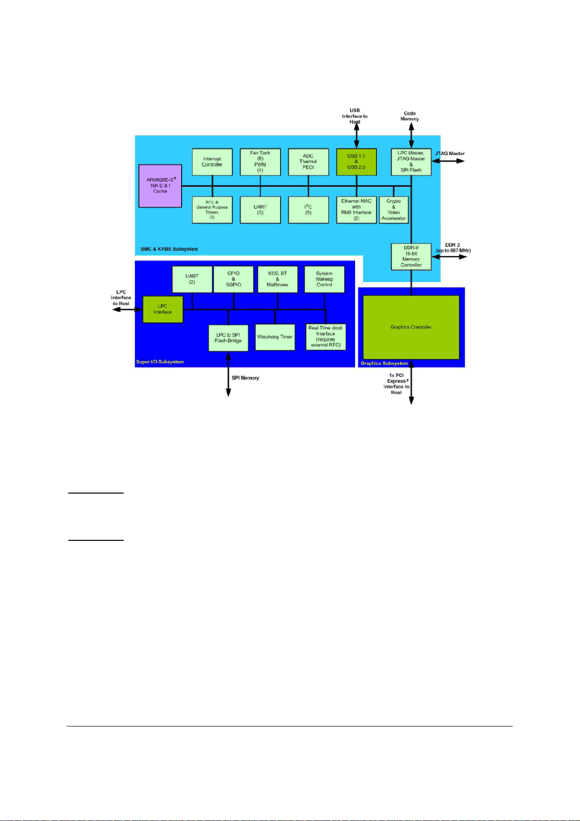
Functional Architecture Intel® Server Boards S5520HC, S5500HCV, and S5520HCT TPS
Figure 20. Integrated BMC Hardware
3.7.1 BMC Embedded LAN Channel
The BMC hardware includes two dedicated 10/100 network interfaces, which are given below:
Interface 1:
be shared with the host. Only one NIC may be enabled for management traffic at any time. The
default active interface is onboard NIC1.
Interface 2:
RMM3), which is a dedicated management NIC and not shared with the host.
For these channels, you can enable support for IPMI-over-LAN and DHCP.
For security reasons, embedded LAN channels have the following default settings:
IP Address: Static
All users disabled
IPMI-enabled network interfaces may not be placed on the same subnet. This includes the
®
Intel
RMM3’s onboard network interface and either of the BMC’s embedded network interfaces.
This interface is available from either of the available NIC ports in system that can
This interface is available from Intel® Remote Management Module 3 (Intel®
Revision 1.8
48
Intel order number E39529-013
Page 63

Intel® Server Boards S5520HC, S5500HCV, and S5520HCT TPS Functional Architecture
3.8 Serial Ports
The Intel® Server Boards S5520HC, S5500HCV and S5520HCT provide two serial ports: an
external DB9 serial port and an internal DH-10 serial header. The rear DB9 serial A port is a
fully-functional serial port that can support any standard serial device.
Serial B is an optional port accessible through a 9-pin internal DH-10 header. You can use a
standard DH-10 to DB9 cable to direct serial B to the rear of a chassis. The serial B interface
follows the standard RS232 pin-out as defined in the following table.
Table 13. Serial B Header Pin-out
Pin Signal Name Serial Port B Header Pin-out
1 DCD
2 DSR
3 RX
4 RTS
5 TX
6 CTS
7 DTR
8 RI
9 GND
3.9 Floppy Disk Controller
The Intel® Server Boards S5520HC, S5500HCV and S5520HCT do not support a floppy disk
controller interface. However, the system BIOS recognizes USB floppy devices.
3.10 Keyboard and Mouse Support
The Intel® Server Boards S5520HC, S5500HCV and S5520HCT do not support PS/2* interface
keyboards and mice. However, the system BIOS recognizes USB Specification-compliant
keyboards and mice.
3.11 Video Support
The Intel® Server Boards S5520HC, S5500HCV and S5520HCT integrated BMC include a 2D
SVGA video controller and 8 MB video memory.
The 2D SVGA subsystem supports a variety of modes, up to 1024 x 768 resolution in
8/16/24/32 bpp. It also supports both CRT and LCD monitors with up to an 85-Hz vertical
refresh rate.
Video is accessed using a standard 15-pin VGA connector found on the back edge of the server
boards. You can disable the onboard video controller using the BIOS Setup Utility or when an
add-in video card is detected. The system BIOS provides the option for Dual Monitor Video
operation when an add-in video card is configured in the system.
3.11.1 Video Modes
The integrated video controller supports all standard IBM* VGA modes. The following table
shows the 2D modes supported for both CRT and LCD.
Revision 1.8
Intel order number E39529-013
49
Page 64

Functional Architecture Intel® Server Boards S5520HC, S5500HCV, and S5520HCT TPS
Table 14. Video Modes
2D Mode
640 x 480
800 x 600
1024 x 768
1152 x 864
1280 x 1024
1440 x 900
1600 x 1200
8 bpp
Supported Supported Supported Supported
60, 72, 75, 85 60, 72, 75, 85 60, 72, 75, 85 60, 72, 75, 85
Supported Supported Supported Supported
56, 60, 72, 75, 85 56, 60, 72, 75, 85 56, 60, 72, 75, 85 56, 60, 72, 75, 85
Supported Supported Supported Supported
60, 70, 75, 85 60, 70, 75, 85 60, 70, 75, 85 60, 70, 75, 85
Supported Supported Supported N/A
75 75 75 N/A
Supported Supported Supported N/A
60, 75, 85 60, 75, 85 60 NA
Supported Supported Supported N/A
60 60 60 NA
Supported Supported N/A N/A
60. 65, 70, 75, 85 60. 65, 70 N/A N/A
2D Video Mode Support
16 bpp
24 bpp
32 bpp
Refresh Rate
(Hz)
Refresh Rate
(Hz)
Refresh Rate
(Hz)
Refresh Rate
(Hz)
Refresh Rate
(Hz)
Refresh Rate
(Hz)
Refresh Rate
(Hz)
3.11.2 Dual Video
The BIOS supports single- and dual-video modes. The dual-video mode is enabled by default.
• In single mode, the onboard video controller is disabled when an add-in video card is
detected.
• In dual mode (enable “Dual Monitor Video” in the BIOS setup), the onboard video
controller is enabled and is the primary video device. The add-in video card is allocated
resources and considered the secondary video device.
• The BIOS Setup utility provides options on Advanced | PCI Configuration Screen to
configure the feature as follows:
Onboard Video
Dual Monitor Video
Enabled
(default)
Disabled
Enabled Shaded if onboard video is set to "Disabled"
Disabled
(Default)
Revision 1.8
50
Intel order number E39529-013
Page 65

Intel® Server Boards S5520HC, S5500HCV, and S5520HCT TPS Functional Architecture
3.12 Network Interface Controller (NIC)
The Intel® Server Boards S5520HC, S5500HCV and S5520HCT provide dual onboard LAN
ports with support for 10/100/1000 Mbps operation. The two LAN ports are based on the
onboard Intel
integrated GbE Media Access Control (MAC) and Physical Layer (PHY) ports.
®
82575EB controller, which is a single, compact component with two, fully-
The Intel
®
82575EB controller provides a standard IEEE 802.3 Ethernet interface for
1000BASE-T, 100BASE-TX, and 10BASE-T applications (802.3, 802.3u, and 802.3ab) and is
capable of transmitting and receiving data at rates of 1000 Mbps, 100 Mbps, or 10 Mbps.
Each network interface controller (NIC) port provides two LEDs:
Link/activity LED (at the left of the connector): Indicates network connection when on,
and transmit/receive activity when blinking.
The speed LED (at the right of the connector) indicates 1000-Mbps operation when
amber; 100-Mbps operation when green; and 10-Mbps when off. The following table
provides an overview of the LEDs.
Table 15. Onboard NIC Status LED
LED Color
Green (Left)
Off/Green/Amber (Right)
On Active Connection
Blinking Transmit/Receive activity
Off 10 Mbps
Green 100 Mbps
Amber 1000 Mbps
LED State
NIC State
3.12.1 MAC Address Definition
Each Intel® Server Board S5520HC or S5500HCV has the following four MAC addresses
assigned to it at the Intel factory.
• NIC 1 MAC address
• NIC 2 MAC address - is assigned the NIC 1 MAC address +1
• BMC LAN Channel MAC address – is assigned the NIC 1 MAC address +2
®
• Intel
During the manufacturing process, each server board has a white MAC address sticker placed
on the top of the NIC 1 port. The sticker displays the NIC 1 MAC address and Intel
in both bar code and alphanumeric formats.
Revision 1.8
Remote Management Module 3 (Intel® RMM3) MAC address – is assigned the
NIC 1 MAC address +3
Intel order number E39529-013
®
RMM3 MAC
51
Page 66

Functional Architecture Intel® Server Boards S5520HC, S5500HCV, and S5520HCT TPS
3.13 *Trusted Platform Module (TPM) – Supported only on S5520HCT
3.13.1 Overview
Trusted Platform Module (TPM) is a hardware-based security device that addresses the growing
concern on boot process integrity and offers better data protection. TPM protects the system
start-up process by ensuring it is tamper-free before releasing system control to the operating
system. A TPM device provides secured storage to store data, such as security keys and
passwords. In addition, a TPM device has encryption and hash functions. The Intel
Board S5520HCT implements TPM as per TPM PC Client specifications revision 1.2 by the
Trusted Computing Group (TCG).
A TPM device is affixed to the motherboard of the server and is secured from external software
attacks and physical theft. A pre-boot environment, such as the BIOS and operating system
loader, uses the TPM to collect and store unique measurements from multiple factors within the
boot process to create a system fingerprint. This unique fingerprint remains the same unless the
pre-boot environment is tampered with. Therefore, it is used to compare to future
measurements to verify the integrity of the boot process.
After the BIOS complete the measurement of its boot process, it hands off control to the
operating system loader and in turn to the operating system. If the operating system is TPMenabled, it compares the BIOS TPM measurements to those of previous boots to make sure the
system was not tampered with before continuing the operating system boot process. Once the
operating system is in operation, it optionally uses TPM to provide additional system and data
security (for example, Microsoft Vista* supports Bitlocker drive encryption).
®
Server
3.13.2 TPM security BIOS
The BIOS TPM support conforms to the TPM PC Client Specific – Implementation Specification
for Conventional BIOS, version 1.2, and to the TPM Interface specification, version 1.2. The
BIOS adheres to the Microsoft Vista* BitLocker requirement. The role of the BIOS for TPM
security includes the following:
• Measures and stores the boot process in the TPM microcontroller to allow a TPM
enabled operating system to verify system boot integrity.
• Produces EFI and legacy interfaces to a TPM-enabled operating system for using
TPM.
• Produces ACPI TPM device and methods to allow a TPM-enabled operating system
to send TPM administrative command requests to the BIOS.
• Verifies operator physical presence. Confirms and executes operating system TPM
administrative command requests.
• Provides BIOS Setup options to change TPM security states and to clear TPM
ownership.
For additional details, refer to the TCG PC Client Specific Implementation Specification, the
TCG PC Client Specific Physical Presence Interface Specification, and the Microsoft BitLocker*
Requirement documents.
Revision 1.8
52
Intel order number E39529-013
Page 67

Intel® Server Boards S5520HC, S5500HCV, and S5520HCT TPS Functional Architecture
3.13.2.1 Physical Presence
Administrative operations to the TPM require TPM ownership or physical presence indication by
the operator to confirm the execution of administrative operations. The BIOS implements the
operator presence indication by verifying the setup Administrator password.
A TPM administrative sequence invoked from the operating system proceeds as follows:
1. User makes a TPM administrative request through the operating system’s security software.
2. The operating system requests the BIOS to execute the TPM administrative command
through TPM ACPI methods and then resets the system.
The BIOS verifies the physical presence and confirms the command with the operator.
3.
4. T
he BIOS executes TPM administrative command(s), inhibits BIOS Setup entry and boots
directly to the operating system which requested the TPM command(s).
3.13.2.2 TPM Security Setup Options
The BIOS TPM Setup allows the operator to view the current TPM state and to carry out
rudimentary TPM administrative operations. Performing TPM administrative options through the
BIOS setup requires TPM physical presence verification.
Using BIOS TPM Setup, the operator can turn ON or OFF TPM functionality and clear the TPM
ownership contents. After the requested TPM BIOS Setup operation is carried out, the option
reverts to No Operation.
The BIOS TPM Setup also displays the current state of the TPM, whether TPM is enabled or
disabled and activated or deactivated. Note that while using TPM, a TPM-enabled operating
system or application may change the TPM state independent of the BIOS setup. When an
operating system modifies the TPM state, the BIOS Setup displays the updated TPM state.
The BIOS Setup TPM Clear option allows the operator to clear the TPM ownership key and
allows the operator to take control of the system with TPM. You use this option to clear security
settings for a newly initialized system or to clear a system for which the TPM ownership security
key was lost.
3.13.2.3 Security Screen
The Security screen provides fields to enable and set the user and administrative passwords
and to lock out the front panel buttons so they cannot be used. The Intel
®
Server Board
S5520HCT provides TPM settings through the security screen.
To access this screen from the Main screen, select the Security option.
Revision 1.8
Intel order number E39529-013
53
Page 68

Functional Architecture Intel® Server Boards S5520HC, S5500HCV, and S5520HCT TPS
Main Advanced Security Server Management Boot Options Boot Manager
Administrator Password Status <Installed/Not Installed>
User Password Status <Installed/Not Installed>
Set Administrator Password [1234aBcD]
Set User Password [1234aBcD]
Front Panel Lockout Enabled/Disabled
TPM State
TPM Administrative Control No Operation/Turn On/Turn Off/Clear Ownership
<Enabled & Activated/Enabled & Deactivated/Disabled &
Activated/Disabled & Deactivated>
Figure 21. Setup Utility – TPM Configuration Screen
Table 16. TPM Setup Utility – Security Configuration Screen Fields
Setup Item Options Help Text Comments
TPM State* Enabled and Activated
Enabled and Deactivated
Disabled and Activated
Disabled and Deactivated
TPM
Administrative
Control**
No Operation
Turn On
Turn Off
Clear Ownership
[No Operation] - No changes to current
state.
[Turn On] - Enables and activates TPM.
[Turn Off] - Disables and deactivates TPM.
[Clear Ownership] - Removes the TPM
ownership authentication and returns the
TPM to a factory default state.
Note: The BIOS setting returns to [No
Operation] on every boot cycle by default.
Information only.
Shows the current TPM device state.
A disabled TPM device will not
execute commands that use TPM
functions and TPM security
operations will not be available.
An enabled and deactivated TPM is
in the same state as a disabled TPM
except setting of TPM ownership is
allowed if not present already.
An enabled and activated TPM
executes all commands that use
TPM functions and TPM security
operations will be available.
Revision 1.8
54
Intel order number E39529-013
Page 69

Intel® Server Boards S5520HC, S5500HCV, and S5520HCT TPS Functional Architecture
3.13.3 Intel
®
Trusted Execution Technology (Intel® TXT)
3.13.3.1 Overview
®
Intel
Trusted Execution Technology (Intel® TXT) for safer computing, formerly code named
LaGrande Technology, is a versatile set of hardware extensions to Intel
chipsets that enhance the platform with security capabilities such as measured launch and
protected execution. Intel
®
TXT provides hardware-based mechanisms that help protect against
®
processors and
software-based attacks and protects the confidentiality and integrity of data stored or created on
the system. It does this by enabling an environment where applications can run within their own
space, protected from all other software on the system. These capabilities provide the protection
mechanisms, rooted in hardware, that are necessary to provide trust in the application's
execution environment. In turn, this can help to protect vital data and processes from being
compromised by malicious software running on the platform. Long available on client platforms,
Intel is now enabling Intel TXT on selected server platforms as well.
3.13.3.2 Intel
®
TXT hardware overview
Implementation of a Trusted Execution Technology-enabled platform requires a number of
hardware enhancements. Key hardware elements of this platform are:
Processor: Extensions to the IA-32 architecture allow for the creation of multiple execution
environments, or partitions. This allows for the coexistence of a standard (legacy) partition and
protected partition, where software can run in isolation in the protected partition, free from being
observed or compromised by other software running on the platform. Access to hardware
resources (such as memory) is hardened by enhancements in the processor and chipset
hardware. Other processor enhancements include: (1) event handling, to reduce the
vulnerability of data exposed through system events, (2) instructions to manage the protected
execution environment, (3) and instructions to establish a more secure software stack.
Chipset: Extensions to the chipset deliver support for key elements of this new, more protected
platform. They include: (1) the capability to enforce memory protection policy, (2) enhancements
to protect data access from memory, (3) protected channels to graphics and input/output
devices, (4) and interfaces to the Trusted Platform Module [Version 1.2].
Keyboard and Mouse: Enhancements to the keyboard and mouse enable communication
between these input devices and applications running in a protected partition to take place
without being observed or compromised by unauthorized software running on the platform.
Graphics: Enhancements to the graphic subsystem enable applications running within a
protected partition to send display information to the graphics frame buffer without being
observed or compromised by unauthorized software running on the platform.
The TPM v. 1.2 device: Also called the Fixed Token, is bound to the platform and connected to
the PC’s LPC bus. The TPM provides the hardware-based mechanism to store or ‘seal’ keys
and other data to the platform. It also provides the hardware mechanism to report platform
attestations.
3.13.3.3 Enabling Intel
®
TXT can be supported by Intel® Server Board S5520HCT (PBA# E80888-553 or later
Intel
version), following steps describe how to set up Intel
®
TXT on Intel® Server Board
®
TXT feature:
Revision 1.8
Intel order number E39529-013
55
Page 70

Functional Architecture Intel® Server Boards S5520HC, S5500HCV, and S5520HCT TPS
System pre-requirements:
Processor: B1 or later stepping Intel
Server Board: Intel
®
Server Board S5520HCT; PBA version E80888-553 or later
®
Xeon Processor 5600 Series
Memory: At least 1 GB memory installed
®
Intel
TXT Setup:
1 – Enable TPM module:
Go to BIOS setup Menu page, Security Tab, set administrator password.
Figure 22. Setting Administrator password in BIOS
2. After administrator password is setup, press “F10” to save and exit BIOS setup.
3. System will automatically reboot, go to BIOS setup Menu page, Security Tab, set TPM
Administrative Control as “Turn ON”, press “F10” to save and exit BIOS setup.
Revision 1.8
56
Intel order number E39529-013
Page 71

Intel® Server Boards S5520HC, S5500HCV, and S5520HCT TPS Functional Architecture
Figure 23. Activating TPM
4. Go to BIOS setup Menu, Security Tab, TPM State should be “Enabled & Activated”.
Revision 1.8
Intel order number E39529-013
57
Page 72

Functional Architecture Intel® Server Boards S5520HC, S5500HCV, and S5520HCT TPS
Figure 24. TPM activated
5. Go to BIOS Setup Menu, Advanced -> Processor Configuration, set Intel® VT for directed
I/O and Intel
®
TXT option as “Enabled”
Revision 1.8
58
Intel order number E39529-013
Page 73

Intel® Server Boards S5520HC, S5500HCV, and S5520HCT TPS Functional Architecture
Figure 25. BIOS setting for TXT
6. Press “F10” to save and exit, now Intel® TXT is successfully enabled.
3.14 ACPI Support
The Intel® Server Boards S5520HC, S5500HCV and S5520HCT support S0, S1, and S5 states.
S1 is considered a sleep state.
The Intel
using the USB devices in addition to the sources described in the following paragraph.
The wake-up sources are enabled by the ACPI operating systems with cooperation from the
drivers; the BIOS have no direct control over the wake-up sources when an ACPI operating
system is loaded. The role of the BIOS is limited to describing the wake-up sources to the
operating system.
The S5 state is equivalent to the operating system shutdown. No system context is saved when
going into S5.
®
Server Boards S5520HC, S5500HCV and S5520HCT can wake up from S1 state
Revision 1.8
Intel order number E39529-013
59
Page 74

Functional Architecture Intel® Server Boards S5520HC, S5500HCV, and S5520HCT TPS
3.15 Intel
®
Virtualization Technology
Intel® Virtualization Technology is designed to support multiple software environments sharing
the same hardware resources. Each software environment may consist of an operating system
and applications. You can enable or disable the Intel
®
Virtualization Technology in the BIOS
Setup. The default behavior is disabled.
Note: After changing the Intel
®
Virtualization Technology option (disable or enable) in the BIOS
setup, users must perform an AC power cycle before the change takes effect.
3.15.1 Intel
®
Virtualization Technology for Directed IO (VT-d)
The Intel® Server Boards S5520HC, S5500HCV and S5520HCT support DMA remapping from
inbound PCI Express* memory Guest Physical Address (GPA) to Host Physical Address (HPA).
PCI devices are directly assigned to a virtual machine leading to a robust and efficient
virtualization.
You can enable or disable the Intel
®
Virtualization Technology for Directed I/O in the BIOS
Setup. The default behavior is disabled.
Note: After changing the Intel
®
Virtualization Technology for Directed I/O options (disable or
enable) in the BIOS setup, users must perform an AC power cycle before the changes can take
effect.
Revision 1.8
60
Intel order number E39529-013
Page 75

Intel® Server Boards S5520HC, S5500HCV, and S5520HCT TPS Platform Management
4. Platform Management
The platform management subsystem is based on the Integrated BMC features of the
ServerEngines* Pilot II. The onboard platform management subsystem consists of
communication buses, sensors, and the system BIOS, and server management firmware.
Figure 27 provides an illustration of the Server Management Bus (SMBUS) architecture as used
on these server boards.
4.1 Feature Support
4.1.1 IPMI 2.0 Features
• Baseboard management controller (BMC).
• IPMI Watchdog timer.
• Messaging support, including command bridging and user/session support.
• Chassis device functionality, including power/reset control and BIOS boot flags
support.
• Event receiver device: The BMC receives and processes events from other platform
subsystems.
• Field replaceable unit (FRU) inventory device functionality: The BMC supports access
to system FRU devices using IPMI FRU commands.
• System event log (SEL) device functionality: The BMC supports and provides access
to a SEL.
• Sensor data record (SDR) repository device functionality: The BMC supports storage
and access of system SDRs.
• Sensor device and sensor scanning/monitoring: The BMC provides IPMI
management of sensors. It polls sensors to monitor and report system health.
• IPMI interfaces:
- Host interfaces include system management software (SMS) with receive
message queue support and server management mode (SMM).
- IPMB interface.
- LAN interface that supports the IPMI-over-LAN protocol (RMCP, RMCP+).
• Serial-over-LAN (SOL)
• ACPI state synchronization: The BMC tracks ACPI state changes provided by the
BIOS.
• BMC Self-test: The BMC performs initialization and run-time self-tests, and makes
results available to external entities.
See also the Intelligent Platform Management Interface Specification Second Generation v2.0.
4.1.2 Non-IPMI Features
The BMC supports the following non-IPMI features. This list does not preclude support for future
enhancements or additions.
In-circuit BMC firmware update
Revision 1.8
Intel order number E39529-013
61
Page 76

Platform Management Intel® Server Boards S5520HC, S5500HCV, and S5520HCT TPS
• Fault resilient booting (FRB): FRB2 is supported by the watchdog timer functionality.
• Chassis intrusion detection (dependant on platform support)
• Basic fan control using TControl version 2 SDRs
• Fan redundancy monitoring and support
• Power supply redundancy monitoring and support
• Hot swap fan support
• Acoustic management: Supports multiple fan profiles
• Signal testing support: The BMC provides test commands for setting and getting
platform signal states.
• The BMC generates diagnostic beep codes for fault conditions.
• System GUID storage and retrieval
• Front panel management: The BMC controls the system status LED and chassis ID LED.
It supports secure lockout of certain front panel functionality and monitors button presses.
The chassis ID LED is turned on using a front panel button or a command.
• Power state retention
• Power fault analysis
®
• Intel
Light-Guided Diagnostics
• Power unit management: Support for power unit sensor. The BMC handles power-good
dropout conditions.
• DIMM temperature monitoring: New sensors and improved acoustic management using
closed-loop fan control algorithm taking into account DIMM temperature readings.
• Address Resolution Protocol (ARP): The BMC sends and responds to ARPs (supported
on embedded NICs)
• Dynamic Host Configuration Protocol (DHCP): The BMC performs DHCP (supported on
embedded NICs)
• Platform environment control interface (PECI) thermal management support
• E-mail alerting
• Embedded web server
• Integrated KVM
• Integrated Remote Media Redirection
• Local Directory Access Protocol (LDAP) support
®
• Intel
Intelligent Power Node Manger support
Revision 1.8
62
Intel order number E39529-013
Page 77

Intel® Server Boards S5520HC, S5500HCV, and S5520HCT TPS Platform Management
4.2 Optional Advanced Management Feature Support
This section explains the advanced management features supported by the BMC firmware.
Table 17 lists basic and advanced feature support. Individual features may vary by platform. For
more information, refer to Appendix C.
Table 17. Basic and Advanced Management Features
Feature
IPMI 2.0 Feature Support X X
In-circuit BMC Firmware Update X X
FRB 2 X X
Chassis Intrusion Detection X X
Fan Redundancy Monitoring X X
Hot-Swap Fan Support X X
Acoustic Management X X
Diagnostic Beep Code Support X X
Power State Retention X X
ARP/DHCP Support X X
PECI Thermal Management Support X X
E-mail Alerting X X
Embedded Web Server X
SSH Support X X
Integrated KVM X
Integrated Remote Media Redirection X
Local Directory Access Protocol (LDAP) for Linux X
Intel® Intelligent Power Node Manager
Support***
SMASH CLP X X
WS-Management X
* Basic management features provided by integrated BMC
**Advanced management features available with optional Intel
®
***Intel
Intelligent Power Node Manager Support requires PMBus-compliant power supply
Basic*
X X
Advanced**
®
Remote Management Module 3
4.2.1 Enabling Advanced Management Features
BMC will enable advanced management features only when it detects the presence of the Intel®
Remote Management Module 3 (Intel
features are dormant.
®
4.2.1.1 Intel
The Intel
®
RMM3 provides the BMC with an additional dedicated network interface. The
Remote Management Module 3 (Intel® RMM3)
dedicated interface consumes its own LAN channel. Additionally, the Intel
additional flash storage for advanced features such as WS-MAN.
®
RMM3) card. Without the Intel® RMM3, the advanced
®
RMM3 provides
4.2.2 Keyboard, Video, and Mouse (KVM) Redirection
The advanced management features include support for keyboard, video, and mouse
redirection (KVM) over LAN. This feature is available remotely from the embedded web server
as a Java* applet. The client system must have a Java Runtime Environment (JRE) Version 1.6
Revision 1.8
Intel order number E39529-013
63
Page 78

Platform Management Intel® Server Boards S5520HC, S5500HCV, and S5520HCT TPS
(JRE6) or later to run the KVM or media redirection applets. You can download the latest Java
Runtime Environment (JRE) update: http://java.com/en/download/index.jsp
.
This feature is only enabled when the Intel
®
RMM3 is present.
Note: KVM Redirection is only available with onboard video controller, and the onboard video
controller must be enabled and used as the primary video output.
The BIOS will detect one set of USB keyboard and mouse for the KVM redirection function of
®
Intel
RMM3, even if no presence of RMM3 is detected. Users will see one set of USB keyboard
and mouse in addition to the local USB connection on the BIOS Setup USB screen with or
without RMM3 installed.
4.2.2.1 Keyboard and Mouse
The keyboard and mouse are emulated by the BMC as USB human interface devices.
4.2.2.2 Video
Video output from the KVM subsystem is equivalent to video output on the local console via
onboard video controller. Video redirection is available once video is initialized by the system
BIOS. The KVM video resolutions and refresh rates will always match the values set in the
operating system.
4.2.2.3 Availability
Up to two remote KVM sessions are supported. An error displays on the web browser
attempting to launch more than two KVM sessions.
The default inactivity timeout is 30 minutes, but you may change the default through the
embedded web server. Remote KVM activation does not disable the local system keyboard,
video, or mouse. Unless the feature is disabled locally, remote KVM is not deactivated by local
system input.
KVM sessions will persist across system reset but not across an AC power loss.
4.2.3 Media Redirection
The embedded web server provides a Java* applet to enable remote media redirection. You
may use this in conjunction with the remote KVM feature or as a standalone applet.
The media redirection feature is intended to allow system administrators or users to mount a
remote IDE or USB CD-ROM, floppy drive, or a USB flash disk as a remote device to the server.
Once mounted, the remote device appears as a local device to the server, allowing system
administrators or users to boot the server or install software (including operating systems), copy
files, update the BIOS, and so forth, or boot the server from this device.
The following capabilities are supported:
• The operation of remotely mounted devices is independent of the local devices on the
server. Both remote and local devices are usable in parallel.
Revision 1.8
64
Intel order number E39529-013
Page 79

Intel® Server Boards S5520HC, S5500HCV, and S5520HCT TPS Platform Management
• You can mount either IDE (CD-ROM, floppy) or USB devices as a remote device to the
server.
• It is possible to boot all supported operating systems from the remotely mounted device
and to boot from disk IMAGE (*.IMG) and CD-ROM or DVD-ROM ISO files. For more
information, refer to the Tested/supported Operating System List.
• It is possible to mount at least two devices concurrently.
• The mounted device is visible to (and usable by) the managed system’s operating
system and BIOS in both the pre- and post-boot states.
• The mounted device shows up in the BIOS boot order and it is possible to change the
BIOS boot order to boot from this remote device.
• It is possible to install an operating system on a bare metal server (no operating system
present) using the remotely mounted device. This may also require the use of KVM-r to
configure the operating system during install.
If either a virtual IDE or virtual floppy device is remotely attached during system boot, both
virtual IDE and virtual floppy are presented as bootable devices. It is not possible to present
only a single mounted device type to the system BIOS.
4.2.3.1 Availability
The default inactivity timeout is 30 minutes and is not user-configurable.
Media redirection sessions persist across system reset but not across an AC power loss.
4.2.4 Web Services for Management (WS-MAN)
The BMC firmware supports the Web Services for Management (WS-MAN) specification,
version 1.0.
4.2.4.1 Profiles
The BMC supports the following DMTF profiles for WS-MAN:
• Base Server Profile
• Fan Profile
• Physical Asset Profile
• Power State Management Profile
• Profile Registration Profile
• Record Log Profile
• Sensor Profile
• Software Inventory Profile (FW Version)
Note: WS-MAN features will be made available after production launch.
Revision 1.8
Intel order number E39529-013
65
Page 80

Platform Management Intel® Server Boards S5520HC, S5500HCV, and S5520HCT TPS
4.2.5 Embedded Web server
The BMC provides an embedded web server for out-of-band management. User authentication
is handled by IPMI user names and passwords. Base functionality for the embedded web server
includes:
• Power Control
• Sensor Reading
• SEL Reading
• KVM/Media Redirection: Only available when the Intel
• IPMI User Management
The web server is available on all enabled LAN channels. If a LAN channel is enabled, properly
configured, and accessible, the web server is available.
The web server may be contacted via HTTP or HTTPS. A user can modify the SSL certificates
using the web server. You cannot change the web server’s port (80/81).
For security reasons, you cannot use the null user (user 1) to access the web server. The
session inactivity timeout for the embedded web server is 30 minutes. This is not userconfigurable.
®
RMM3 is present.
4.2.6 Local Directory Authentication Protocol (LDAP)
The BMC firmware supports the Linux Local Directory Authentication Protocol (LDAP) protocol
for user authentication. IPMI users/passwords and sessions are not supported over LDAP.
A user can configure LDAP usage through the embedded web server for authentication of future
embedded web sessions.
Note: Supports LDAP for Linux only.
Revision 1.8
66
Intel order number E39529-013
Page 81

Intel® Server Boards S5520HC, S5500HCV, and S5520HCT TPS Platform Management
4.3 Platform Control
This server platform has embedded platform control which is capable of automatically adjusting
system performance and acoustic levels.
PPeerrffoorrmmaannccee
MMaannaaggeemmeennt
AAccoouussttiicc
MMaannaaggeemmeennt
t
IInntteeggrraatteedd
CCoonnttrrooll
t
FFaann SSppeeeedd
CCoonnttrrooll
PPeerrffoorrmmaanncce
TThhrroottttlliinngg
e
TThheerrmmaall
MMoonniittoorriinngg
Figure 26. Platform Control
Platform control optimizes system performance and acoustics levels through:
• Performance management
• Performance throttling
• Thermal monitoring
• Fan speed control
• Acoustics management
The platform components used to implement platform control include:
• Integrated baseboard management controller
• Platform sensors
• Variable speed system fans
• System BIOS
• BMC firmware
• Sensor data records as loaded by the FRUSDR Utility
• Memory type
Revision 1.8
Intel order number E39529-013
67
Page 82

Platform Management Intel® Server Boards S5520HC, S5500HCV, and S5520HCT TPS
4.3.1 Memory Open and Closed Loop Thermal Throttling
Open-Loop Thermal Throttling (OLTT)
Throttling is a solution to cool the DIMMs by reducing memory traffic allowed on the memory
bus, which reduces power consumption and thermal output. With OLTT, the system throttles in
response to memory bandwidth demands instead of actual memory temperature. Since there is
no direct temperature feedback from the DDR3 DIMMs, the throttling behavior is preset rather
than conservatively based on the worst cooling conditions (for example, high inlet temperature
and low fan speeds). Additionally, the fans that provide cooling to the memory region are also
set to conservative settings (for example, higher minimal fan speed). OLTT produces a slightly
louder system than CLTT because minimal fan speeds must be set high enough to support any
DDR3 DIMMs in the worst memory cooling conditions.
Closed-Loop Thermal Throttling (CLTT)
CLTT works by throttling the DDR3 DIMMs response directly to memory temperature via
thermal sensors integrated on the Serial Presence Detect (SPD) of the DDR3 DIMMs. This is
the preferred throttling method because this approach lowers limitations on both memory power
and thermal threshold, therefore minimizing throttling impact on memory performance. This
reduces the utilization of high fan speeds because CLTT does not have to accommodate for the
worst memory cooling conditions; with a higher thermal threshold, CLTT enables memory
performance to achieve optimal levels.
4.3.2 Fan Speed Control
BIOS and BMC software work cooperatively to implement system thermal management support.
During normal system operation, the BMC will retrieve information from the BIOS and monitor
several platform thermal sensors to determine the required fan speeds.
In order to provide the proper fan speed control for a given system configuration, the BMC must
have the appropriate platform data programmed. Platform configuration data is programmed
using the FRUSDR utility during the system integration process and by System BIOS during run
time.
4.3.2.1 System Configuration Using the FRUSDR Utility
The Field Replaceable Unit and Sensor Data Record Update Utility (FRUSDR utility) is a
program used to write platform-specific configuration data to NVRAM on the server board. It
allows the user to select which supported chassis (Intel or Non-Intel) and platform chassis
configuration is used. Based on the input provided, the FRUSDR writes sensor data specific to
the configuration to NVRAM for the BMC controller to read each time the system is powered on.
4.3.2.2 Fan Speed Control from BMC and BIOS Inputs
Using the data programmed to NVRAM by the FRUSDR utility, the BMC is configured to monitor
and control the appropriate platform sensors and system fans each time the system is powered
on. After power-on, the BMC uses additional data provided to it by the System BIOS to
determine how to control the system fans.
The BIOS provides data to the BMC telling it which fan profile the platform is set up for:
Acoustics Mode or Performance Mode. The BIOS uses the parameters retrieved from the
thermal sensor data records (SDR), fan profile setting from BIOS Setup, and altitude setting
from the BIOS Setup to configure the system for memory throttling and fan speed control. If the
Revision 1.8
68
Intel order number E39529-013
Page 83

Intel® Server Boards S5520HC, S5500HCV, and S5520HCT TPS Platform Management
BIOS fails to get the Thermal SDRs, then it uses the Memory Reference Code (MRC) default
settings for the memory throttling settings.
The <F2> BIOS Setup Utility provides options to set the fan profile or operating mode the
platform will operate under. Each operating mode has a predefined profile for which specific
platform targets are configured, which in turn determines how the system fans operate to meet
those targets. Platform profile targets are determined by which type of platform is selected when
running the FRUSDR utility and by the BIOS settings configured using the <F2> BIOS Setup.
4.3.2.2.1 Fan Domains
System fan speeds are controlled through pulse width modulation (PWM) signals, which are
driven separately for each domain by integrated PWM hardware. Fan speed is changed by
adjusting the duty-cycle, which is the percentage of time the signal is driven high in each pulse.
Refer to Appendix D for system specific fan domains.
Table 18. S5520HC, S5500HCV and S5520HCT Fan Domain Table
Fan Domain Onboard Fan Header
Fan Domain 0 CPU 1 Fan, CPU 2 Fan
Fan Domain 1 System Fan 5
Fan Domain 2 System Fan 1, System Fan 2
Fan Domain 3 System Fan 3, System Fan 4
4.3.2.3 Configuring the Fan Profile Using the BIOS Setup Utility
The BIOS uses options set in the <F2> BIOS Setup Utility to determine what fan profile the
system should operate under. These options include “THROTTLING MODE”, “ALTITUDE”, and
“SET FAN PROFILE”. Refer to “Section 5.3.2.2.7 System Acoustic and Performance
Configuration” for details of the BIOS options.
The “ALTITUDE” option is used to determine appropriate memory performance settings based
on the different cooling capability at different altitudes. At high altitude, memory performance
must be reduced to compensate for thinner air. Be advised, selecting an Altitude option to a
setting that does not meet the operating altitude of the server may limit the system fans’ ability
to provide adequate cooling to the memory. If the air flow is not sufficient to meet the needs of
the server even after throttling has occurred, the system may shut down due to excessive
platform thermals.
By default, the Altitude option is set to 301 m – 900 m which is believed to cover the majority of
the operating altitudes for these server platforms.
You can set the “SET FAN PROFILE” option to either the Performance mode (Default) or
Acoustics mode. Refer to the following sections for details describing the differences between
each mode. Changing the fan profile to Acoustics mode may affect system performance. The
“SET FAN PROFILE” BIOS option is hidden when CLTT is selected as the THROTTLING
MODE option.
4.3.2.3.1 Performance Mode (Default)
With the platform running in Performance mode (Default), several platform control algorithm
variables are set to enhance the platform’s capability of operating at maximum performance
targets for the given system. In doing so, the platform is programmed with higher fan speeds at
lower ambient temperatures. This results in a louder acoustic level than is targeted for the given
Revision 1.8
Intel order number E39529-013
69
Page 84

Platform Management Intel® Server Boards S5520HC, S5500HCV, and S5520HCT TPS
platform, but the increased airflow of this operating mode greatly reduces both possible memory
throttling from occurring and dynamic fan speed changes based on processor utilization.
4.3.2.3.2 Acoustics Mode
With the platform running in Acoustics mode, several platform control algorithm variables are set
to ensure acoustic targets are not exceeded for specified Intel platforms. In this mode, the
platform is programmed to set the fans at lower speeds when the processor does not require
additional cooling due to high utilization/power consumption. Memory throttling is used to ensure
memory thermal limits are not exceeded.
Note: Fan speed control for a non-Intel chassis, as configured after running the FRUSDR utility
and selecting the Non-Intel Chassis option, is limited to only the CPU fans. The BMC only
requires the processor thermal sensor data to determine how fast to operate these fans. The
remaining system fans will operate at 100% operating limits due to unknown variables
associated with the given chassis and its fans. Therefore, regardless of whether the system is
configured for Performance Mode or Acoustics Mode, the system fans will always run at 100%
operating levels providing for maximum airflow. In this scenario, the Performance and Acoustic
mode settings only affect the allowable performance of the memory (higher BW for the
Performance mode).
4.4 Intel
®
Intelligent Power Node Manager
Intel® Intelligent Power Node Manager is a platform (system)-level solution that provides the
system with a method of monitoring power consumption and thermal output, and adjusting
system variables to control those factors.
The BMC supports Intel
the platform must have an Intel
®
Intelligent Power Node Manager specification version 1.5. Additionally,
®
Intelligent Power Node Manager capable Manageability Engine
(ME) firmware installed.
The BMC firmware implements power-management features based on the Power Management
Bus (PMBus) 1.1 Specification.
Note: Intelligent Power Node Manager is only available on platforms that support PMBus-
compliant power supplies.
4.4.1 Manageability Engine (ME)
An embedded ARC controller is within the IOH providing the Intel® Server Platform Services
(SPS). The controller is also commonly referred to as the Manageability Engine (ME).
The functionality provided by the SPS firmware is different from Intel
Technology (Intel
®
AMT) provided by the ME on client platforms.
®
Active Management
Revision 1.8
70
Intel order number E39529-013
Page 85

Intel® Server Boards S5520HC, S5500HCV, and S5520HCT TPS Platform Management
Revision 1.8
Figure 27. SMBUS Block Diagram
71
Intel order number E39529-013
Page 86

BIOS Setup Utility Intel® Server Boards S5520HC, S5500HCV, and S5520HCT TPS
5. BIOS Setup Utility
5.1 Logo/Diagnostic Screen
The Logo/Diagnostic Screen displays in one of two forms:
• If Quiet Boot is enabled in the BIOS setup, a logo splash screen is displayed. By default,
Quiet Boot is enabled in the BIOS setup. If the logo displays during POST, press <Esc>
to hide the logo and display the diagnostic screen.
• If a logo is not present in the flash ROM or if Quiet Boot is disabled in the system
configuration, the summary and diagnostic screen is displayed.
The diagnostic screen displays the following information:
• BIOS ID
• Platform name
• Total memory detected (Total size of all installed DDR3 DIMMs)
• Processor information (Intel branded string, speed, and number of physical processors
identified)
• Keyboards detected (if plugged in)
• Mouse devices detected (if plugged in)
5.2 BIOS Boot Popup Menu
The BIOS Boot Specification (BBS) provides for a Boot Popup Menu invoked by pressing the
<F6> key during POST. The BBS popup menu displays all available boot devices. The list order
in the popup menu is not the same as the boot order in the BIOS setup; it simply lists all the
bootable devices from which the system can be booted.
When a User Password or Administrator Password is active in Setup, the password is to access
the Boot Popup Menu.
5.3 BIOS Setup Utility
The BIOS Setup utility is a text-based utility that allows the user to configure the system and
view current settings and environment information for the platform devices. The Setup utility
controls the platform's built-in devices, boot manager, and error manager.
The BIOS Setup interface consists of a number of pages or screens. Each page contains
information or links to other pages. The advanced tab in Setup displays a list of general
categories as links. These links lead to pages containing a specific category’s configuration.
The following sections describe the look and behavior for platform setup.
5.3.1 Operation
The BIOS Setup has the following features:
Revision 1.8
72
Intel order number E39529-013
Page 87

Intel® Server Boards S5520HC, S5500HCV, and S5520HCT TPS BIOS Setup Utility
Localization - The BIOS Setup uses the Unicode standard and is capable of displaying
setup forms in all languages currently included in the Unicode standard. The Intel
®
server board BIOS is only available in English.
Console Redirection - The BIOS Setup is functional via console redirection over various
terminal emulation standards. This may limit some functionality for compatibility (for
example, color usage or some keys or key sequences or support of pointing devices).
5.3.1.1 Setup Page Layout
The setup page layout is sectioned into functional areas. Each occupies a specific area of the
screen and has dedicated functionality. The following table lists and describes each functional
area.
Table 19. BIOS Setup Page Layout
Functional Area Description
Title Bar The title bar is located at the top of the screen and displays the title of the form
(page) the user is currently viewing. It may also display navigational information.
Setup Item List The Setup Item List is a set of controllable and informational items. Each item in the
list occupies the left column of the screen.
A Setup Item may also open a new window with more options for that functionality
on the board.
Item Specific Help Area The Item Specific Help area is located on the right side of the screen and contains
help text for the highlighted Setup Item. Help information may include the meaning
and usage of the item, allowable values, effects of the options, and so forth.
Keyboard Command Bar The Keyboard Command Bar is located at the bottom right of the screen and
continuously displays help for keyboard special keys and navigation keys.
5.3.1.2 Entering BIOS Setup
To enter the BIOS Setup, press the F2 function key during boot time when the OEM or Intel logo
displays. The following message displays on the diagnostics screen and under the Quiet Boot
logo screen:
Press <F2> to enter setup
When the Setup is entered, the Main screen displays. However, serious errors cause the
system to display the Error Manager screen instead of the Main screen.
5.3.1.3 Keyboard Commands
The bottom right portion of the Setup screen provides a list of commands used to navigate
through the Setup utility. These commands display at all times.
Each Setup menu page contains a number of features. Each feature is associated with a value
field except those used for informative purposes. Each value field contains configurable
parameters. Depending on the security option selected and in effect by the password, a menu
feature’s value may or may not change. If a value cannot be changed, its field is made
inaccessible and appears grayed out.
Revision 1.8
Intel order number E39529-013
73
Page 88

BIOS Setup Utility Intel® Server Boards S5520HC, S5500HCV, and S5520HCT TPS
Table 20. BIOS Setup: Keyboard Command Bar
Key Option Description
<Enter>
<Esc>
↑
↓
↔
<Tab>
-
+
<F9>
<F10>
Execute
Command
Exit The <Esc> key provides a mechanism for backing out of any field. When the <Esc>
Select Item The up arrow is used to select the previous value in a pick list, or the previous
Select Item The down arrow is used to select the next value in a menu item’s option list, or a
Select Menu The left and right arrow keys are used to move between the major menu pages.
Select Field The <Tab> key is used to move between fields. For example, you can use <Tab>
Change Value The minus key on the keypad is used to change the value of the current item to the
Change Value The plus key on the keypad is used to change the value of the current menu item
Setup Defaults Pressing <F9> causes the following to display:
Save and Exit Pressing <F10> causes the following message to display:
The <Enter> key is used to activate sub-menus when the selected feature is a submenu, or to display a pick list if a selected option has a value field, or to select a
sub-field for multi-valued features like time and date. If a pick list is displayed, the
<Enter> key selects the currently highlighted item, undoes the pick list, and returns
the focus to the parent menu.
key is pressed while editing any field or selecting features of a menu, the parent
menu is re-entered.
When the <Esc> key is pressed in any sub-menu, the parent menu is re-entered.
When the <Esc> key is pressed in any major menu, the exit confirmation window is
displayed and the user is asked whether changes can be discarded. If “No” is
selected and the <Enter> key is pressed, or if the <Esc> key is pressed, the user is
returned to where they were before <Esc> was pressed, without affecting any
existing settings. If “Yes” is selected and the <Enter> key is pressed, the setup is
exited and the BIOS returns to the main System Options Menu screen.
option in a menu item's option list. The selected item must then be activated by
pressing the <Enter> key.
value field’s pick list. The selected item must then be activated by pressing the
<Enter> key.
The keys have no effect if a sub-menu or pick list is displayed.
to move from hours to minutes in the time item in the main menu.
previous value. This key scrolls through the values in the associated pick list
without displaying the full list.
to the next value. This key scrolls through the values in the associated pick list
without displaying the full list. On 106-key Japanese keyboards, the plus key has a
different scan code than the plus key on the other keyboards, but will have the
same effect.
Load Optimized Defaults?
Yes No
If “Yes” is highlighted and <Enter> is pressed, all Setup fields are set to their
default values. If “No” is highlighted and <Enter> is pressed, or if the <Esc> key is
pressed, the user is returned to where they were before <F9> was pressed without
affecting any existing field values.
Save configuration and reset?
Yes No
If “Yes” is highlighted and <Enter> is pressed, all changes are saved and the Setup
is exited. If “No” is highlighted and <Enter> is pressed, or the <Esc> key is
pressed, the user is returned to where they were before <F10> was pressed
without affecting any existing values.
Revision 1.8
74
Intel order number E39529-013
Page 89

Intel® Server Boards S5520HC, S5500HCV, and S5520HCT TPS BIOS Setup Utility
5.3.1.4 Menu Selection Bar
The Menu Selection Bar is located at the top of the BIOS Setup Utility screen. It displays the
major menu selections available to the user. By using the left and right arrow keys, the user can
select the menus listed here. Some menus are hidden and become available by scrolling off the
left or right of the current selections.
5.3.2 Server Platform Setup Utility Screens
The following sections describe the screens available for the configuration of a server platform.
In these sections, tables are used to describe the contents of each screen. These tables follow
the following guidelines:
• The Setup Item, Options, and Help Text columns in the tables document the text and
values that also display on the BIOS Setup screens.
• In the Options column, the default values are displayed in bold. These values are not
displayed in bold on the BIOS Setup screen. The bold text in this document serves as a
reference point.
• The Comments column provides additional information where it may be helpful. This
information does not display on the BIOS Setup screens.
• Information enclosed in angular brackets (< >) in the screen shots identifies text that can
vary, depending on the option(s) installed. For example <Current Date> is replaced by
the actual current date.
• Information enclosed in square brackets ([ ]) in the tables identifies areas where the user
must type in text instead of selecting from a provided option.
• Whenever information is changed (except Date and Time), the systems requires a save
and reboot to take place. Pressing <ESC> discards the changes and boots the system
according to the boot order set from the last boot.
Revision 1.8
Intel order number E39529-013
75
Page 90

BIOS Setup Utility Intel® Server Boards S5520HC, S5500HCV, and S5520HCT TPS
5.3.2.1 Main Screen
Unless an error occurred, the Main screen is the first screen displayed when the BIOS Setup is
entered. If an error occurred, the Error Manager screen displays instead.
Main Advanced Security Server Management Boot Options Boot Manager
Logged in as <Administrator or User>
Platform ID
System BIOS
Version S5500.86B.xx.yy.zzzz
Build Date <MM/DD/YYYY>
Memory
Total Memory <How much memory is installed>
Quiet Boot Enabled/Disabled
POST Error Pause Enabled/Disabled
System Date <Current Date>
System Time <Current Time>
<Platform Identification String>
Figure 28. Setup Utility — Main Screen Display
Table 21. Setup Utility — Main Screen Fields
Setup Item Options Help Text Comments
Logged in as
Platform ID
System BIOS
Version
Build Date
Memory
Revision 1.8
76
Intel order number E39529-013
Information only. Displays
password level that setup is
running in: Administrator or User.
With no passwords set,
Administrator is the default mode.
Information only. Displays the
Platform ID.
Information only. Displays the
current BIOS version.
xx = major version
yy = minor version
zzzz = build number
Information only. Displays the
current BIOS build date.
Page 91

Intel® Server Boards S5520HC, S5500HCV, and S5520HCT TPS BIOS Setup Utility
Setup Item Options Help Text
Size
Quiet Boot
POST Error Pause Enabled
System Date [Day of week
System Time [HH:MM:SS] System Time has configurable
Enabled
Disabled
Disabled
MM/DD/YYYY]
[Enabled] – Display the logo screen
during POST.
[Disabled] – Display the diagnostic
screen during POST.
[Enabled] – Go to the Error
Manager for critical POST errors.
[Disabled] – Attempt to boot and do
not go to the Error Manager for
critical POST errors.
System Date has configurable
fields for Month, Day, and Year.
Use [Enter] or [Tab] key to select
the next field.
Use [+] or [-] key to modify the
selected field.
fields for Hours, Minutes, and
Seconds.
Hours are in 24-hour format.
Use [Enter] or [Tab] key to select
the next field.
Use [+] or [-] key to modify the
selected field.
Comments
Information only. Displays the
total physical memory installed in
the system, in MB or GB. The term
physical memory indicates the total
memory discovered in the form of
installed DDR3 DIMMs.
If enabled, the POST Error Pause
option takes the system to the error
manager to review the errors when
major errors occur. Minor and fatal
error displays are not affected by
this setting.
Revision 1.8
77
Intel order number E39529-013
Page 92

BIOS Setup Utility Intel® Server Boards S5520HC, S5500HCV, and S5520HCT TPS
5.3.2.2 Advanced Screen
The Advanced screen provides an access point to configure several options. On this screen, the
user selects the option they must configure. Configurations are performed on the selected
screen and not directly on the Advanced screen.
To access this screen from the Main screen, press the right arrow until the Advanced screen is
selected.
Main Advanced Security Server Management Boot Options Boot Manager
► Processor Configuration
► Memory Configuration
► Mass Storage Controller Configuration
► Serial Port Configuration
► USB Configuration
► PCI Configuration
► System Acoustic and Performance Configuration
Figure 29. Setup Utility — Advanced Screen Display
Table 22. Setup Utility — Advanced Screen Display Fields
Setup Item Help Text
Processor Configuration
Memory Configuration
Mass Storage Controller Configuration
Serial Port Configuration
USB Configuration
PCI Configuration
System Acoustic and Performance
Configuration
View/Configure processor information and
settings.
View/Configure memory information and
settings.
View/Configure mass storage controller
information and settings.
View/Configure serial port information and
settings.
View/Configure USB information and
settings.
View/Configure PCI information and
settings.
View/Configure system acoustic and
performance information and settings.
Revision 1.8
78
Intel order number E39529-013
Page 93

Intel® Server Boards S5520HC, S5500HCV, and S5520HCT TPS BIOS Setup Utility
5.3.2.2.1 Processor Configuration Screen
The Processor screen allows the user to view the processor core frequency, system bus
frequency, and to enable or disable several processor options. This screen also allows the user
to view information about a specific processor. To access this screen from the Main screen,
select Advanced > Processor.
Advanced
Processor Configuration
Processor Socket CPU 1 CPU 2
Processor ID <CPUID> <CPUID>
Processor Frequency <Proc Freq> <Proc Freq>
Microcode Revision <Rev data> <Rev data>
L1 Cache RAM Size of Cache
L2 Cache RAM
L3 Cache RAM
Processor 1 Version <ID string from Processor 1>
Processor 2 Version <ID string from Processor 2> or Not Present
Current Intel® QPI Link Speed <Slow/Fast >
Intel® QPI Link Frequency <Unknown GT/s/4.8 GT/s/5.866 GT/s/6.4 GT/s>
Intel® Turbo Boost Technology Enabled/Disabled
Enhanced Intel SpeedStep® Tech Enabled/Disabled
Intel® Hyper-Threading Tech Enabled/Disabled
Core Multi-Processing All/1/2
Execute Disable Bit Enabled/Disabled
Intel® Virtualization Technology Enabled/ Disabled
Intel® VT for Directed I/O Enabled/ Disabled
Interrupt Remapping Enabled/Disabled
Coherency Support Enabled/ Disabled
ATS Support Enabled/Disabled
Pass-through DMA Support Enabled/Disabled
Hardware Prefetcher Enabled/Disabled
Adjacent Cache Line Prefetch Enabled/Disabled
Direct Cache Access (DCA)
Enabled/Disabled
Size of Cache Size of Cache
Size of Cache Size of Cache
Size of Cache
Figure 30. Setup Utility — Processor Configuration Screen Display
Revision 1.8
79
Intel order number E39529-013
Page 94

BIOS Setup Utility Intel® Server Boards S5520HC, S5500HCV, and S5520HCT TPS
®
®
®
®
Table 23. Setup Utility — Processor Configuration Screen Fields
Setup Item Options Help Text Comments
Processor ID
Processor Frequency
Microcode Revision
L1 Cache RAM
L2 Cache RAM
L3 Cache RAM
Processor 1 Version
Processor 2 Version
Current Intel® QPI Link
Speed
Intel® QPI Link
Frequency
Intel® Turbo Boost
Technolgy
Enhanced Intel
SpeedStep
®
Tech
Intel® Hyper-Threading
Tech
Core Multi-Processing
Enabled
Disabled
Enabled
Disabled
Enabled
Disabled
All
1
2
Execute Disable Bit
Enabled
Disabled
Intel® Virtualization
Technology
Enabled
Disabled
Turbo Boost Technology allows the
Intel
processor to automatically increase its
frequency if it is running below power,
temperature, and current specifications.
Enhanced Intel SpeedStep
Technology
allows the system to dynamically adjust
processor voltage and core frequency, which
can result in decreased average power
consumption and decreased average heat
production.
Contact your OS vendor regarding OS
support of this feature.
Intel
HT Technology allows multithreaded
software applications to execute threads in
parallel within each processor.
Contact your OS vendor regarding OS
support of this feature.
Enable 1, 2 or All cores of installed
processors packages.
Execute Disable Bit can help prevent certain
classes of malicious buffer overflow attacks.
Contact your OS vendor regarding OS
support of this feature.
Virtualization Technology allows a
Intel
platform to run multiple operating systems
and applications in independent partitions.
Note: A change to this option requires the
system to be powered off and then back on
before the setting takes effect.
Information only. Processor
CPUID
Information only. Current
frequency of the processor.
Information only. Revision of
the loaded microcode.
Information only. Size of the
Processor L1 Cache.
Information only. Size of the
Processor L2 Cache
Information only. Size of the
Processor L3 Cache.
Information only. ID string
from the Processor.
Information only. ID string
from the Processor.
Information only. Current
speed that the QPI Link is
using.
Information only. Current
frequency that the QPI Link is
using.
This option is only visible if all
processors in the system
support Intel
®
Turbo Boost
Technology.
Revision 1.8
80
Intel order number E39529-013
Page 95

Intel® Server Boards S5520HC, S5500HCV, and S5520HCT TPS BIOS Setup Utility
®
®
®
®
Setup Item Options Help Text
Intel® Virtualization
Technology for Directed
Enabled
Disabled
I/O
Interrupt Remapping
Enabled
Disabled
Coherency Support
Enabled
Disabled
ATS Support
Enabled
Disabled
Pass-through DMA
Support
Hardware Prefetcher
Enabled
Disabled
Enabled
Disabled
Adjacent Cache Line
Prefetch
Direct Cache Access
(DCA)
Enabled
Disabled
Enabled
Disabled
Enable/Disable Intel® Virtualization
Technology for Directed I/O.
Report the I/O device assignment to VMM
through DMAR ACPI Tables
Enable/Disable Intel
VT-d Interrupt
Remapping support.
Enable/Disable Intel
VT-d Coherency
support.
Enable/Disable Intel
VT-d Address
Translation Services (ATS) support.
Enable/Disable Intel
VT-d Pass-through
DMA support.
Hardware Prefetcher is a speculative
prefetch unit within the processor(s).
Note: Modifying this setting may affect
system performance.
[Enabled] - Cache lines are fetched in pairs
(even line + odd line).
[Disabled] - Only the current cache line
required is fetched.
Note: Modifying this setting may affect
system performance.
Allows processors to increase the I/O
performance by placing data from I/O
devices directly into the processor cache.
Comments
Only appears when Intel®
Virtualization Technology for
Directed I/O is enabled.
Only appears when Intel®
Virtualization Technology for
Directed I/O is enabled.
Only appears when Intel®
Virtualization Technology for
Directed I/O is enabled.
Only appears when Intel®
Virtualization Technology for
Directed I/O is enabled.
Revision 1.8
81
Intel order number E39529-013
Page 96

BIOS Setup Utility Intel® Server Boards S5520HC, S5500HCV, and S5520HCT TPS
5.3.2.2.2 Memory Screen
The Memory screen allows the user to view details about the system memory DDR3 DIMMs
installed. This screen also allows the user to open the Configure Memory RAS and Performance
screen.
To access this screen from the Main screen, select Advanced > Memory.
Advanced
Memory Configuration
Total Memory <Total Physical Memory Installed in System>
Effective Memory <Total Effective Memory>
Current Configuration <Independent/Mirror>
Current Memory Speed <Speed that installed memory is running at.>
► Memory RAS and Performance Configuration
DIMM Information
DIMM_A1 Installed/Not Installed/Failed/Disabled
DIMM_A2 Installed/Not Installed/Failed/Disabled
DIMM_B1 Installed/Not Installed/Failed/Disabled
DIMM_B2 Installed/Not Installed/Failed/Disabled
DIMM_C1 Installed/Not Installed/Failed/Disabled
DIMM_C2 Installed/Not Installed/Failed/Disabled
DIMM_D1 Installed/Not Installed/Failed/Disabled
DIMM_D2 Installed/Not Installed/Failed/Disabled
DIMM_E1 Installed/Not Installed/Failed/Disabled
DIMM_E2 Installed/Not Installed/Failed/Disabled
DIMM_F1 Installed/Not Installed/Failed/Disabled
DIMM_F2 Installed/Not Installed/Failed/Disabled
Figure 31. Setup Utility — Memory Configuration Screen Display
Revision 1.8
82
Intel order number E39529-013
Page 97

Intel® Server Boards S5520HC, S5500HCV, and S5520HCT TPS BIOS Setup Utility
Table 24. Setup Utility — Memory Configuration Screen Fields
Setup Item Options Help Text Comments
Total Memory
Effective Memory
Current Configuration
Current Memory
Speed
Memory RAS and
Performance
Configuration
DIMM_ XY Displays the state of each DIMM socket
Configure memory RAS
(Reliability, Availability,
and Serviceability) and
view current memory
performance information
and settings.
Information only. The amount of memory
available in the system in the form of
installed DDR3 DIMMs in units of MB or
GB.
Information only. The amount of memory
available to the operating system in MB or
GB.
The Effective Memory is the difference
between Total Physical Memory and the
sum of all memory reserved for internal
usage, RAS redundancy and SMRAM.
This difference includes the sum of all
DDR3 DIMMs that failed Memory BIST
during POST, or were disabled by the
BIOS during memory discovery phase in
order to optimize memory configuration.
Information only. Displays one of the
following:
– Indepen dent Mode: System
memory is configured for optimal
performance and efficiency and no
RAS is enabled.
– Mirror Mode: System memory is
configured for maximum reliability in
the form of memory mirroring.
Information only. Displays the speed the
memory is running at.
Select to configure the memory RAS and
performance. This takes the user to a
different screen.
present on the board. Each DIMM socket
field reflects one of the following possible
states:
– Installed: There is a DDR3 DIMM
installed in this slot.
– Not Installed: There is no DDR3
DIMM installed in this slot.
– Disabled: The DDR3 DIMM installed
in this slot was disabled by the BIOS
to optimize memory configuration.
– Failed: The DDR3 DIMM installed in
this slot is faulty/malfunctioning.
Note: X denotes the Channel Identifier and
Y denote the DIMM Identifier within the
Channel.
Revision 1.8
Intel order number E39529-013
83
Page 98

BIOS Setup Utility Intel® Server Boards S5520HC, S5500HCV, and S5520HCT TPS
5.3.2.2.2.1 Configure Memory RAS and Performance Screen
The Configure Memory RAS and Performance screen allows the user to customize several
memory configuration options, such as whether to use Memory Mirroring.
To access this screen from the Main screen, select Advanced > Memory > Configure Memory
RAS and Performance.
Memory RAS and Performance Configuration
Capabilities
Memory Mirroring Possible Yes/No
Select Memory RAS Configuration Maximum Performance/Mirroring
NUMA Optimized Disabled/ Enabled
Advanced
Figure 32. Setup Utility — Configure RAS and Performance Screen Display
Table 25. Setup Utility — Configure RAS and Performance Screen Fields
Setup Item Options Help Text Comments
Memory Mirroring
Possible
Select Memory
RAS Configuration
NUMA Optimized
Yes/No
Maximum
Performance
Mirroring
Enabled
Disabled
Available modes depend on the current
memory population.
[Maximum Performance] - Optimizes
system performance.
[Mirroring] - Optimizes reliability by
using half of physical memory as a
backup.
If enabled, BIOS includes ACPI tables
that are required for NUMA aware
Operating Systems.
Information only. Only displayed
on systems with chipsets capable
of Memory Mirroring.
Only available if Mirroring is
possible.
Revision 1.8
84
Intel order number E39529-013
Page 99

Intel® Server Boards S5520HC, S5500HCV, and S5520HCT TPS BIOS Setup Utility
5.3.2.2.3 Mass Storage Controller Screen
The Mass Storage screen allows the user to configure the SATA/SAS controller when it is
present on the baseboard module card of an Intel system.
To access this screen from the Main menu, select Advanced > Mass St orage.
Advanced
Mass Storage Controller Configuration
Intel® SAS Entry RAID Module Enabled/Disabled
Configure Intel® SAS Entry RAID Module IT/IR RAID/Intel® ESRTII
Onboard SATA Controller Enabled/Disabled
Configure SATA Mode ENHANCED/COMPATIBILITY/AHCI/SW RAID
► SATA Port 0 Not Installed/<Drive Info.>
► SATA Port 1 Not Installed/<Drive Info.>
► SATA Port 2 Not Installed/<Drive Info.>
► SATA Port 3 Not Installed/<Drive Info.>
► SATA Port 4 Not Installed/<Drive Info.>
► SATA Port 5 Not Installed/<Drive Info.>
Figure 33. Setup Utility — Mass Storage Controller Configuration Screen Display
Revision 1.8
85
Intel order number E39529-013
Page 100

BIOS Setup Utility Intel® Server Boards S5520HC, S5500HCV, and S5520HCT TPS
Table 26. Setup Utility — Mass Storage Controller Configuration Screen Fields
Setup Item Options Help Text Comments
Intel® Entry SAS RAID
Module
Configure Intel® Entry
SAS RAID Module
Onboard SATA
Controller
SATA Mode
SATA Port 0 < Not
SATA Port 1 < Not
SATA Port 2 < Not
SATA Port 3 < Not
SATA Port 4 < Not
SATA Port 5
Enabled
Disabled
IT/IR RAID
®
Intel
ESRTII
Enabled
Disabled
Enhanced
Compatibility
AHCI
SW RAID
Installed/Driv
e
information>
Installed/Driv
e
information>
Installed/Driv
e
information>
Installed/Driv
e
information>
Installed/Driv
e
information>
< Not
Installed/Driv
e
information>
Enabled or Disable the Intel® SAS Entry RAID
Module
IT/IR RAID – Supports Entry-Level HW RAID 0,
RAID 1, and RAID 1e, as well as native SAS
pass through mode; Intel
®
ESRTII - Intel®
Embedded Server RAID Technology II, which
supports RAID 0, RAID 1, RAID 10 and RAID 5
mode. RAID 5 support requires optional
Software RAID 5 Activation Key
Onboard Serial ATA (SATA) controller.
[ENHANCED] - Supports up to 6 SATA ports
with IDE Native Mode.
[COMPATIBILITY] - Supports up to 4 SATA
ports[0/1/2/3] with IDE Legacy mode and 2
SATA ports[4/5] with IDE Native Mode.
[AHCI] - Supports all SATA ports using the
Advanced Host Controller Interface.
[SW RAID] - Supports configuration of SATA
ports for RAID via RAID configuration software.
Unavailable if the SAS Module
(AXX4SASMOD) is not present.
Unavailable if the SAS Module
(AXX4SASMOD) is disabled or
not present.
No longer displays when the
Onboard SATA Controller is
disabled.
Changing this setting requires a
reboot before you can set the
HDD boot order.
[SW RAID] option is unavailable
when EFI Optimized Boot is
Enabled. SW RAID can only be
used in Legacy Boot mode.
Information only. This field is
unavailable when RAID Mode is
enabled.
Information only. This field is
unavailable when RAID Mode is
enabled.
Information only. This field is
unavailable when RAID Mode is
enabled.
Information only. This field is
unavailable when RAID Mode is
enabled.
Information only. This field is
unavailable when RAID Mode is
enabled.
Information only. This field is
unavailable when RAID Mode is
enabled.
Revision 1.8
86
Intel order number E39529-013
 Loading...