

Page 1

Intel® Gigabit Ethernet Switch
AXXSW1GB User Guide
A Guide for System Administrators of Intel® Server Products
Intel Order Number D95362-004
Page 2

Disclaimer
Information in this document is provided in connection with Intel® products. No license, express or implied, by
estoppel or otherwise, to any intellectual property rights is granted by this document. Except as provided in Intel's
Terms and Conditions of Sale for such products, Intel assumes no liability whatsoever, and Intel disclaims any
express or implied warranty, relating to sale and/or use of Intel products including liability or warranties relating to
fitness for a particular purpose, merchantability, or infringement of any patent, copyright or other intellectual property
right. Intel products are not intended for use in medical, life saving, or life sustaining applications.
Intel may make changes to specifications and product descriptions at any time, without notice.
Intel and Intel Xeon are trademarks or registered trademarks of Intel Corporation or its subsidiaries in the United
States and other countries.
Other names and brands may be claimed as the property of others.
Copyright © 2007, Intel Corporation. All Rights Reserved.
ii Intel® Gigabit Ethernet Switch AXXSW1GB User Guide
Page 3

Safety Information
Important Safety Instructions
Read all caution and safety statements in this document before performing any of the
instructions. See also Intel® Server Boards and Server Chassis Safety Information at
http://support.intel.com/support/motherboards/server/sb/cs-010770.htm.
Wichtige Sicherheitshinweise
Lesen Sie zunächst sämtliche Warnund Sicherheitshinweise in diesem Dokument, bevor
Sie eine der Anweisungen ausführen. Beachten Sie hierzu auch die el Server Boards and
Server Chassis Safety Information unter http://support.intel.com/support/motherboards/
server/sb/cs-010770.htm.
Consignes de sécurité
Lisez attention toutes les consignes de sécurité et les mises en garde indiquées dans ce
document avant de suivre toute instruction. Consultez Intel Server Boards and Server
Chassis Safety Information sur le site http://support.intel.com/support/motherboards/
server/sb/cs-010770.htm.
Instrucciones de seguridad importantes
Lea todas las declaraciones de seguridad y precaución de este documento antes de realizar
cualquiera de las instrucciones. Vea Intel Server Boards and Server Chassis Safety
Information en http://support.intel.com/support/motherboards/server/sb/cs-010770.htm.
重要安全指导
Intel® Gigabit Ethernet Switch AXXSW1GB User Guide iii
Page 4

Warnings
These warnings and cautions apply whenever you remove the server compute module
enclosure cover to access components inside the system. Only a technically qualified
person should maintain or configure the system.
Heed safety instructions: Before working with your server product, whether you are
using this guide or any other resource as a reference, pay close attention to the safety
instructions. You must adhere to the assembly instructions in this guide to ensure and
maintain compliance with existing product certifications and approvals. Use only the
described, regulated components specified in this guide. Use of other products /
components will void the UL listing and other regulatory approvals of the product and
will most likely result in noncompliance with product regulations in the region(s) in which
the product is sold.
System power on/off: The power button DOES NOT turn off the system AC power. To
remove power from the system, you must unplug the AC power cord from the wall outlet
or the chassis. Make sure the AC power cord is unplugged before you open the chassis,
add, or remove any components.
Hazardous conditions, devices and cables: Hazardous electrical conditions may be
present on power, telephone, and communication cables. Turn off the system and
disconnect the power cord, telecommunications systems, networks, and modems attached
to the system before opening it. Otherwise, personal injury or equipment damage can
result.
Electrostatic discharge (ESD) and ESD protection: ESD can damage disk drives,
boards, and other parts. We recommend that you perform all procedures in this document
only at an ESD workstation. If one is not available, provide some ESD protection by
wearing an anti-static wrist strap attached to chassis ground (any unpainted metal surface)
on your system when handling parts.
ESD and handling electronic devices: Always handle electronic devices carefully. They
can be extremely sensitive to ESD. Do not touch the connector contacts.
Installing or removing jumpers: A jumper is a small plastic encased conductor that slips
over two jumper pins. Some jumpers have a small tab on top that you can grip with your
fingertips or with a pair of fine needle nosed pliers. If your jumpers do not have such a
tab, take care when using needle nosed pliers to remove or install a jumper; grip the
narrow sides of the jumper with the pliers, never the wide sides. Gripping the wide sides
can damage the contacts inside the jumper, causing intermittent problems with the
function controlled by that jumper. Take care to grip with, but not squeeze, the pliers or
other tool you use to remove a jumper, or you may bend or break the pins on the board.
Reinstalling enclosure cover: To protect internal components and for proper cooling and
airflow, the server compute module should not be inserted into the chassis with the cover
removed; operating it without the enclosure cover in place can damage system parts.
iv Intel® Gigabit Ethernet Switch AXXSW1GB User Guide
Page 5

Preface
The Embedded Web System (EWS) is a network management system. The Embedded Web
Interface configures, monitors, and troubleshoots network devices from a remote web
browser. The Embedded Web Interface web pages are easy-to-use and easy-to-navigate. In
addition, The Embedded Web Interface provides real time graphs and RMON statistics to
help system administrators monitor network performance.
This preface provides an overview to the Embedded Interface User Guide, and includes
the following sections:
• User Guide Overview
• Intended Audience
User Guide Overview
This section provides an overview to the Web System Interface User Guide. The Web
System Interface User Guide provides the following sections:
• Section 1, Getting Started — Provides information about using the EWS, including
The Embedded Web Interface interface, management, and information buttons, as
well as information about adding, modifying, and deleting device information.
• Section 2, Managing Device Information — Provides information about opening
the device zoom view, defining general system information, and enabling Jumbo
frames.
• Section 3, Configuring Device Security — Provides information about configuring
device security for management security, traffic control, and network security.
• Section 4, Configuring Ports — Provides information about configuring ports.
• Section 5, Aggregating Ports — Provides information about configuring Link
Aggregated Groups and LACP.
• Section 6, Configuring VLANs — Provides information about configuring and
managing VLANs, including information about GARP and GVRP, and defining
VLAN groups.
• Section 7, Defining Forwarding Database — Provides information about defining
Static Forwarding Database Entries and Dynamic Forward Database Entries.
• Section 8, Configuring Multicast Forwarding — Provides information about
Multicast Forwarding.
• Section 9, Configuring Spanning Tree — Provides information about configuring
Spanning Tree Protocol and the Rapid Spanning Tree Protocol.
• Section 10, Configuring Quality of Service — Provides information about
configuring Quality of Service on the device.
Intel® Gigabit Ethernet Switch AXXSW1GB User Guide v
Page 6

• Section 11, Managing System Logs — Provides information about enabling and
defining system logs.
• Section 12, Managing Device Diagnostics — Provides information on Configuring
Port Mirroring, Ethernet Ports, and Viewing Optical Transceivers.
• Section 13, Viewing Statistics — Provides information about viewing device
statistics, including RMON statistics, device history events, and port and LAG
utilization statistics.
Intended Audience
This guide is intended for network administrators familiar with IT concepts and
terminology.
vi Intel® Gigabit Ethernet Switch AXXSW1GB User Guide
Page 7

Table of Contents
Safety Information ..................................................................................................... iii
Important Safety Instructions ................................................................................................ iii
Wichtige Sicherheitshinweise ............................................................................................... iii
Consignes de sécurité .......................................................................................................... iii
Instrucciones de seguridad importantes ............................................................................... iii
Preface .........................................................................................................................v
User Guide Overview .............................................................................................................v
Intended Audience ................................................................................................................ vi
Chapter 1: Getting Started .........................................................................................1
Starting the Embedded Web Interface ...................................................................................2
Understanding the Embedded Web Interface ........................................................................3
Using Screen and Table Options ...........................................................................................6
Resetting the Device ..............................................................................................................8
Logging Off the Device ..........................................................................................................8
Chapter 2: Managing Device Information .................................................................9
Viewing System Information ..................................................................................................9
Chapter 3: Configuring Device Security ................................................................. 11
Configuring Traffic Control ...................................................................................................11
Defining Access Control Lists ..............................................................................................17
Chapter 4: Configuring Ports ..................................................................................31
Chapter 5: Aggregating Ports .................................................................................35
Configuring LAGs ................................................................................................................36
Defining LAG Members .......................................................................................................40
Configuring LACP ................................................................................................................42
Configuring Virtual Trunk Group Failover ............................................................................44
Chapter 6: Configuring VLANs ................................................................................47
Defining VLAN Properties ....................................................................................................48
Defining VLAN Membership ................................................................................................50
Defining VLAN Interface Settings ........................................................................................53
Defining VLAN Groups ........................................................................................................56
Configuring GARP ...............................................................................................................66
Chapter 7: Defining Forwarding Database .............................................................71
Defining Static Forwarding Database Entries ......................................................................72
Defining Dynamic Forwarding Database Entries .................................................................74
Intel® Gigabit Ethernet Switch AXXSW1GB User Guide vii
Page 8

Chapter 8: Configuring Multicast Forwarding ........................................................77
Defining IGMP Snooping ..................................................................................................... 78
Defining Multicast Groups ................................................................................................... 80
Defining Multicast Forward All Settings ............................................................................... 83
Chapter 9: Configuring Spanning Tree ...................................................................85
Defining Spanning Tree ....................................................................................................... 86
Defining Spanning Tree Interface Settings .......................................................................... 89
Defining Rapid STP .............................................................................................................93
Defining Multiple STP ..........................................................................................................96
Defining Multiple STP Instance To VLAN Settings .............................................................. 97
Chapter 10: Configuring Quality of Service .........................................................103
Quality of Service Overview .............................................................................................. 104
Defining General QoS Settings ......................................................................................... 105
Configuring Basic QoS Settings ........................................................................................ 114
Configuring Advanced QoS Settings ................................................................................. 117
Chapter 11: Managing System Logs .....................................................................129
Enabling System Logs ....................................................................................................... 130
Viewing the FLASH Logs .................................................................................................. 132
Viewing the Device Memory Logs ..................................................................................... 133
Chapter 12: Managing Device Diagnostics ..........................................................135
Configuring Port Mirroring ................................................................................................. 136
Ethernet Ports Diagnostics ................................................................................................ 138
Copper Cable Extended Feature ....................................................................................... 139
Viewing the CPU Utilization ............................................................................................... 141
Chapter 13: Viewing Statistics ...............................................................................143
Viewing Statistics .............................................................................................................. 143
Viewing Interface Statistics ............................................................................................... 143
Managing RMON Statistics ............................................................................................... 150
A Troubleshooting ..................................................................................................166
B Installation/Assembly Safety Instructions ........................................................168
English ............................................................................................................................... 168
Deutsch ............................................................................................................................. 170
Français ............................................................................................................................. 173
Español ............................................................................................................................. 175
Italiano ............................................................................................................................... 177
C Safety Information ...............................................................................................180
English ............................................................................................................................... 180
Français ............................................................................................................................. 191
viii Intel® Gigabit Ethernet Switch AXXSW1GB User Guide
Page 9

List of Tables
Table 1. Additional Information and Software ...........................................................................8
Table 2. Product Certification Markings ..................................................................................42
Intel® Gigabit Ethernet Switch AXXSW1GB User Guide ix
Page 10

x Intel® Gigabit Ethernet Switch AXXSW1GB User Guide
Page 11

List of Figures
Figure 1. Embedded Web Interface Home Page ...................................................................... 2
Figure 2. Embedded Web Interface Components..................................................................... 3
Figure 3. Device Representation............................................................................................... 4
Figure 4. Add MAC Based ACL................................................................................................. 6
Figure 5. Storm Control Settings Page...................................................................................... 7
Figure 6. Reset Page ................................................................................................................ 8
Figure 7. System Information Page........................................................................................... 9
Figure 8. Reset Page .............................................................................................................. 10
Figure 9. Storm Control Page.................................................................................................. 12
Figure 10. Storm Control Settings Page.................................................................................. 13
Figure 11. Port Security Page ................................................................................................. 14
Figure 12. Edit Port Security Settings Page............................................................................ 16
Figure 13. MAC Based ACL Page........................................................................................... 18
Figure 14. Add MAC Based ACL and First Rule Page............................................................ 20
Figure 15. Add ACL Rule Page............................................................................................... 20
Figure 16. Edit Rule Page ....................................................................................................... 21
Figure 17. IP Based ACL Page ............................................................................................... 22
Figure 18. Add IP Based ACL and First Rule Page ................................................................ 25
Figure 19. Add IP Based Rule Page ....................................................................................... 26
Figure 20. Edit Rule Page ....................................................................................................... 27
Figure 21. ACL Binding Page.................................................................................................. 28
Figure 22. Edit ACL Binding Page........................................................................................... 29
Figure 23. Port Configuration Page......................................................................................... 31
Figure 24. Port Configuration Settings Page........................................................................... 33
Figure 25. LAG Configuration Page ........................................................................................ 36
Figure 26. LAG Configuration Settings Page .......................................................................... 37
Figure 27. LAG Membership Page.......................................................................................... 40
Figure 28. LAG Membership Settings Page............................................................................ 41
Figure 29. LACP Parameters Page......................................................................................... 42
Figure 30. LACP Parameters Settings Page........................................................................... 43
Figure 31. Trunk Group Fail Over Page.................................................................................. 45
Figure 32. Edit Fail Over Group Page..................................................................................... 46
Figure 33. VLAN Properties Page........................................................................................... 48
Figure 34. Add VLAN Page..................................................................................................... 49
Figure 35. VLAN Settings Page .............................................................................................. 49
Figure 36. VLAN Membership Page........................................................................................ 50
Figure 37. Edit VLAN Membership Page ................................................................................ 52
Figure 38. Interface Settings Page.......................................................................................... 53
Figure 39. VLAN Interface Settings Page ............................................................................... 55
Figure 40. VLAN MAC-based Groups Page............................................................................ 57
Figure 41. Add VLAN MAC-based Groups Page .................................................................... 58
Figure 42. MAC Groups Settings Page................................................................................... 58
Intel® Gigabit Ethernet Switch AXXSW1GB User Guide xi
Page 12

Figure 43. VLAN Subnet-based Groups Page........................................................................ 59
Figure 44. Add VLAN Subnet-based Groups Page ................................................................ 60
Figure 45. Subnet-based Group Settings ............................................................................... 60
Figure 46. VLAN Protocol Groups Page................................................................................. 61
Figure 47. Add Protocol-based Groups Page......................................................................... 62
Figure 48. Protocol-based Groups Settings Page .................................................................. 63
Figure 49. Mapping Groups to VLAN Page ............................................................................ 64
Figure 50. Mapping Groups to VLAN Settings Page .............................................................. 65
Figure 51. GARP Settings Page ............................................................................................. 66
Figure 52. GARP Parameters Settings Page.......................................................................... 67
Figure 53. GVRP Parameters Page........................................................................................ 68
Figure 54. GVRP Parameters Settings Page.......................................................................... 69
Figure 55. Static Addresses Page .......................................................................................... 72
Figure 56. Add Static MAC Address Page.............................................................................. 73
Figure 57. Dynamic Addresses Page ..................................................................................... 74
Figure 58. IGMP Snooping Page............................................................................................ 78
Figure 59. IGMP Snooping Settings Page.............................................................................. 79
Figure 60. Multicast Group Page ............................................................................................ 80
Figure 61. Add Multicast Group Page..................................................................................... 81
Figure 62. Edit Multicast Group Page..................................................................................... 82
Figure 63. Multicast Forward All Page.................................................................................... 83
Figure 64. Edit Multicast Forward All Page............................................................................. 84
Figure 65. Spanning Tree Properties Page ............................................................................ 86
Figure 66. Spanning Tree Interface Settings Page................................................................. 89
Figure 67. Spanning Tree Interface Settings Page................................................................. 92
Figure 68. Rapid STP Page.................................................................................................... 93
Figure 69. Rapid Spanning Tree Settings Page ..................................................................... 95
Figure 70. Multiple STP Properties Page ............................................................................... 96
Figure 71. Instance To VLAN Settings Page .......................................................................... 97
Figure 72. Instance Settings Page.......................................................................................... 98
Figure 73. Interface Settings Page ....................................................................................... 100
Figure 74. Interface Table Page ........................................................................................... 102
Figure 75. CoS Global Settings Page................................................................................... 106
Figure 76. Modify Port Priority Page..................................................................................... 107
Figure 77. Queue Page......................................................................................................... 108
Figure 78. Bandwidth Settings Page..................................................................................... 110
Figure 79. Modify Bandwidth Settings Page......................................................................... 111
Figure 80. CoS to Queue Page............................................................................................. 112
Figure 81. DSCP to Queue Page.......................................................................................... 113
Figure 82. Basic Mode General Settings Page..................................................................... 114
Figure 83. QoS DSCP Rewrite Page.................................................................................... 116
Figure 84. Policied DSCP Page............................................................................................ 118
Figure 85. Class Map Page .................................................................................................. 119
Figure 86. Add QoS Class Map Page................................................................................... 120
Figure 87. Aggregated Policier Page.................................................................................... 121
Figure 88. Add Aggregated Policier Page............................................................................. 122
Figure 89. Edit QoS Aggregate Policer Page ....................................................................... 122
xii Intel® Gigabit Ethernet Switch AXXSW1GB User Guide
Page 13

Figure 90. Policy Table Page ................................................................................................ 124
Figure 91. Add QoS Policy Profile Page ............................................................................... 125
Figure 92. Edit QoS Policy Profile Page................................................................................ 126
Figure 93. Policy Binding Page ............................................................................................. 127
Figure 94. Add Qos Policy Binding Page .............................................................................. 128
Figure 95. Qos Policy Binding Settings Page........................................................................ 128
Figure 96. System Logs Properties Page.............................................................................. 130
Figure 97. System Flash Logs Page ..................................................................................... 132
Figure 98. Device Memory Log Page.................................................................................... 133
Figure 99. Port Mirroring Page.............................................................................................. 136
Figure 100. Ethernet Ports Page........................................................................................... 138
Figure 101. Cable Extended Feature Page........................................................................... 139
Figure 102. CPU Utilization Page.......................................................................................... 141
Figure 103. Interface Statistics Page .................................................................................... 144
Figure 104. Etherlike Statistics Page .................................................................................... 146
Figure 105. GVRP Statistics Page ........................................................................................ 148
Figure 106. RMON Statistics Page ....................................................................................... 150
Figure 107. RMON History Control Page.............................................................................. 154
Figure 108. Add History Entry Settings Page........................................................................ 155
Figure 109. RMON History Control Settings Page................................................................ 156
Figure 110. RMON History Table Page................................................................................. 157
Figure 111. RMON Events Control Page .............................................................................. 159
Figure 112. RMON Events Logs Page.................................................................................. 161
Figure 113. RMON Alarm Page ............................................................................................ 162
Figure 114. Add Alarm Entry Page........................................................................................ 163
Figure 115. RMON Alarms Definition Page........................................................................... 164
Intel® Gigabit Ethernet Switch AXXSW1GB User Guide xiii
Page 14

1 Getting Started
This section provides an introduction to the user interface, and includes the following
topics:
• Starting the Embedded Web Interface
• Understanding the Embedded Web Interface
• Using Screen and Table Options
• Resetting the Device
• Logging Off the Device
Intel® Gigabit Ethernet Switch AXXSW1GB User Guide 1
Page 15
Starting the Embedded Web Interface
Note: Disable the popup blocker in your internet browser before beginning device configuration
using the EWS.
This section contains information on starting the Embedded Web Interface.
To access the user interface:
1. Open an internet browser.
2. Ensure that pop-up blockers are disabled. If pop-up blockers are enabled, the edit,
add, and device information messages may not open.
3. Enter the device IP address in the address bar and press Enter.
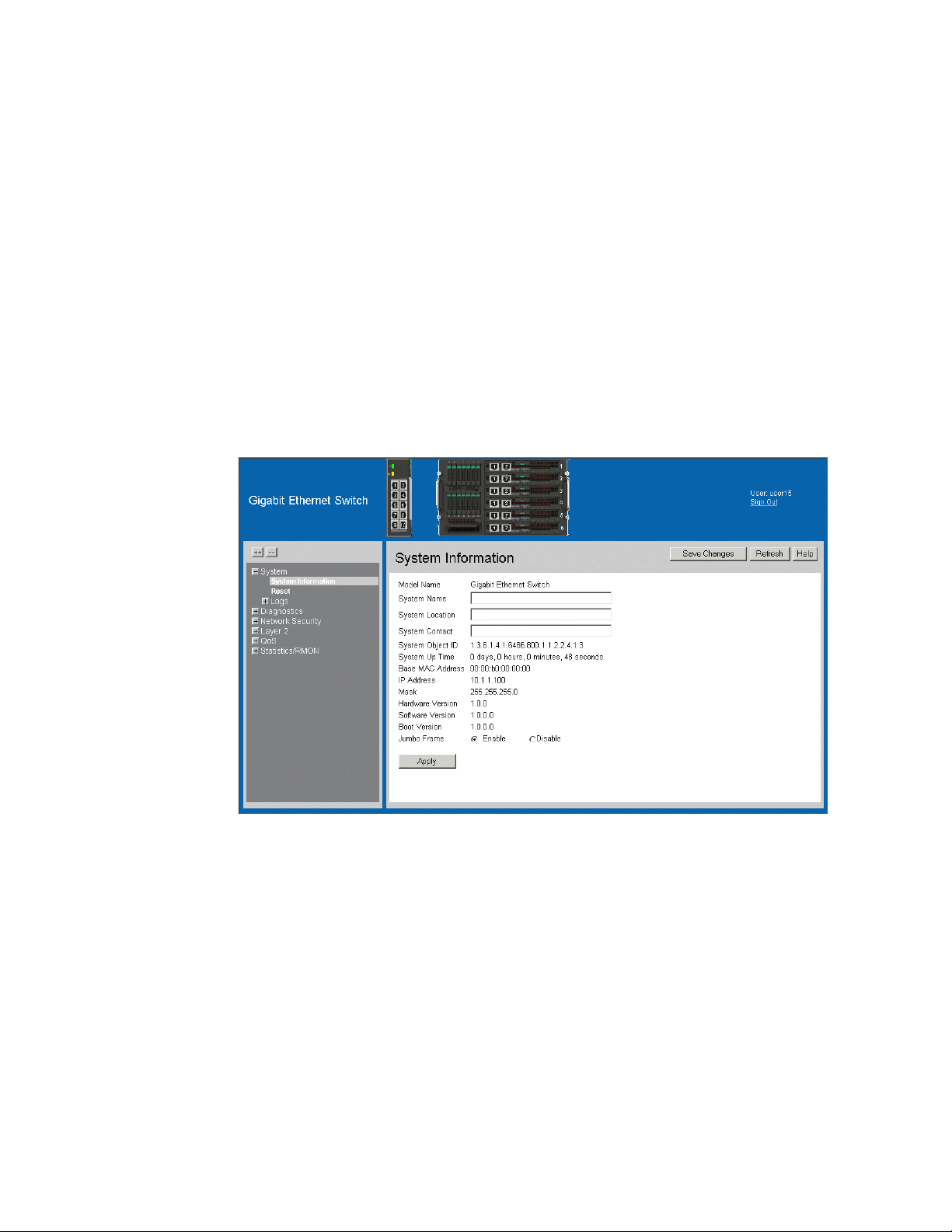
Figure 1. Embedded Web Interface Home Page
2 Intel® Gigabit Ethernet Switch AXXSW1GB User Guide
Page 16
Understanding the Embedded Web Interface
The Embedded Web Interface Home Page contains the following views:
• Port LED Indicators — Located at the top of the home page, the port LED indicators
provide a visual representation of the ports on the front panel.
• Tab Are a — Located under the LED indicators, the tab area contains a list of the
device features and their components.
• Device View — Located in the main part of the home page, the device view provides
a view of the device, an information or table area, and configuration instructions.
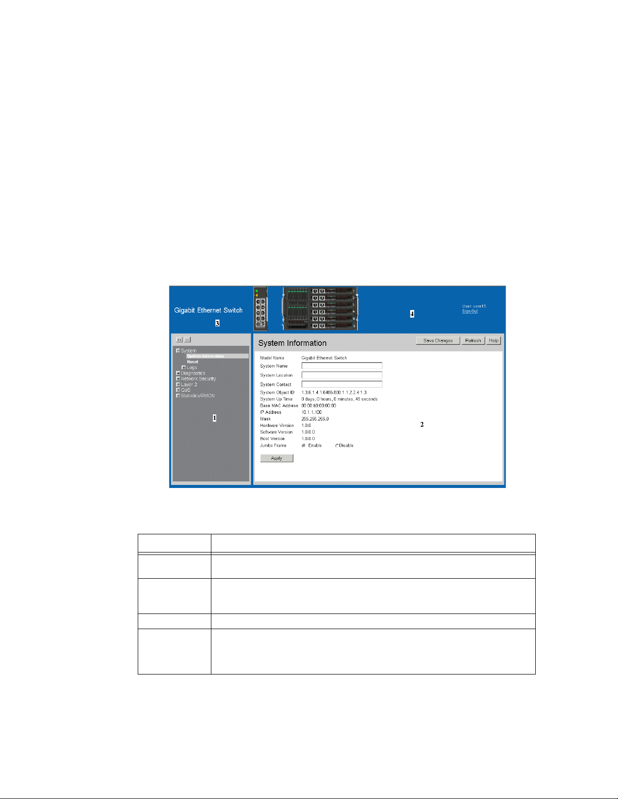
Figure 2. Embedded Web Interface Components
The following table lists the user interface components with their corresponding numbers:
Table 1. Interface Components
View Description
1 Tree View Tree View provides easy navigation through the configurable device features.
The main branches expand to display the sub-features.
2 Device
Information
View
3 Zoom View Provides a graphic of the device on which the Web Interface runs.
4 Web
Interface
Information
Links
Intel® Gigabit Ethernet Switch AXXSW1GB User Guide 3
Device View provides information about device ports, current configuration
and status, table information, and feature components. Device View also
displays other device information and dialog boxes for configuring parameters.
Provides user information, and allows users to save the current device
configuration, and sign out of the Web Interface.
Page 17
This section provides the following additional information:
• Device Representation — Provides an explanation of the user interface buttons,
including both management buttons and task icons.
• Using the Embedded Web Interface Management Buttons — Provides
instructions for adding, modifying, and deleting configuration parameters.
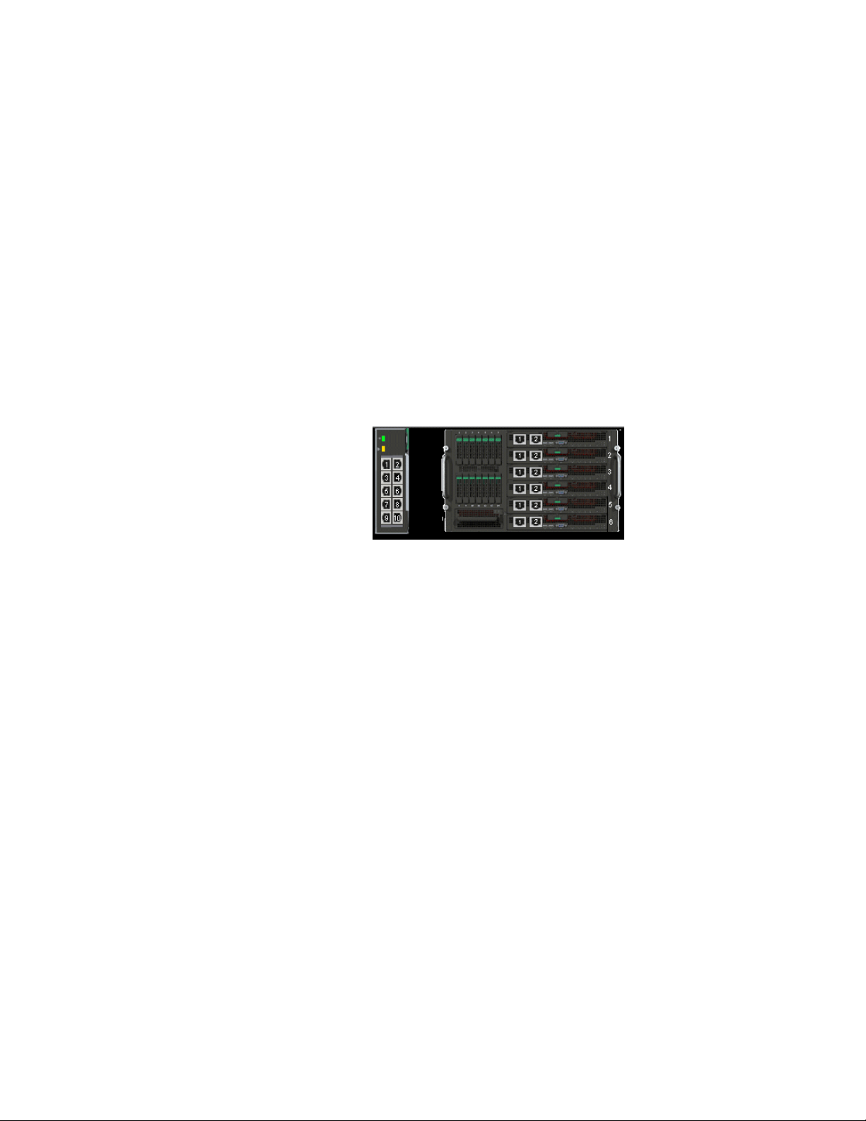
Device Representation
The Embedded Web Interface Home Page contains a graphical panel representation of the
device. An explanation of the port settings displays when you move your mouse over the
port.
Figure 3. Device Representation
4 Intel® Gigabit Ethernet Switch AXXSW1GB User Guide
Page 18
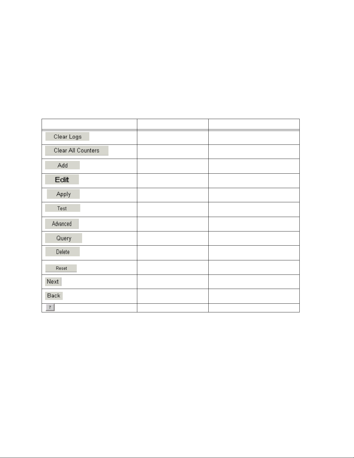
Using the Embedded Web Interface Management Buttons
Configuration Management buttons and icons provide an easy method of configuring
device information, and include the following:
Table 2.
Table 1: Web Interface Configuration Buttons
Button Button Name Description
Clear Logs Clears system logs.
Clear All Counters Clears statistics.
Create Enables creation of configuration
entries.
Edit Modifies configuration settings.
Apply Applies configuration changes to the
device.
Test Performs cable tests.
Advanced Performs advanced tests.
Query Queries the device table.
Delete Deletes a configuration entries.
Reset Resets configuration to before
Next Allows viewing the next page in a
Back Allows to viewing the previous page
Help Opens the online help.
changes were entered by user.
table.
in a table.
Intel® Gigabit Ethernet Switch AXXSW1GB User Guide 5
Page 19
Using Screen and Table Options
This option contains screens and tables for configuring devices. This section contains the
following topics:
• Adding Configuration Information
• Modifying Configuration Information
• Deleting Configuration Information
Adding Configuration Information
User-defined information can be added to specific Web Interface pages, by opening a new
Add page.
To add information to tables or Web Interface pages:
1. Open an Embedded Web Interface page.
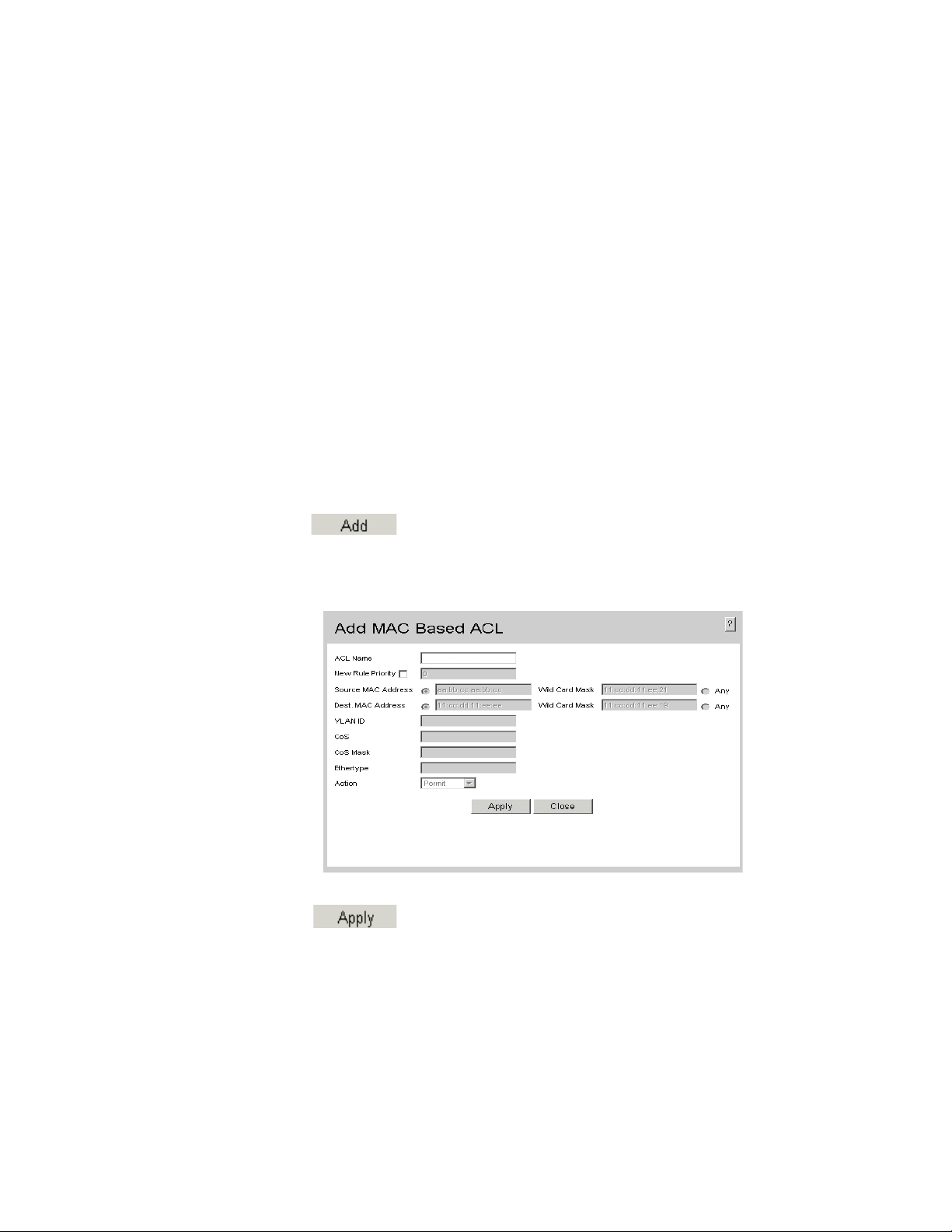
2. Click . An add page opens, such as the Add MAC Based ACL:
Figure 4. Add MAC Based ACL
3. Define the relevant fields.
4. Click . The configuration information is saved, and the device is
updated.
6 Intel® Gigabit Ethernet Switch AXXSW1GB User Guide
Page 20
Modifying Configuration Information
1. Open an Embedded Web Interface page.
2. Select a table entry.
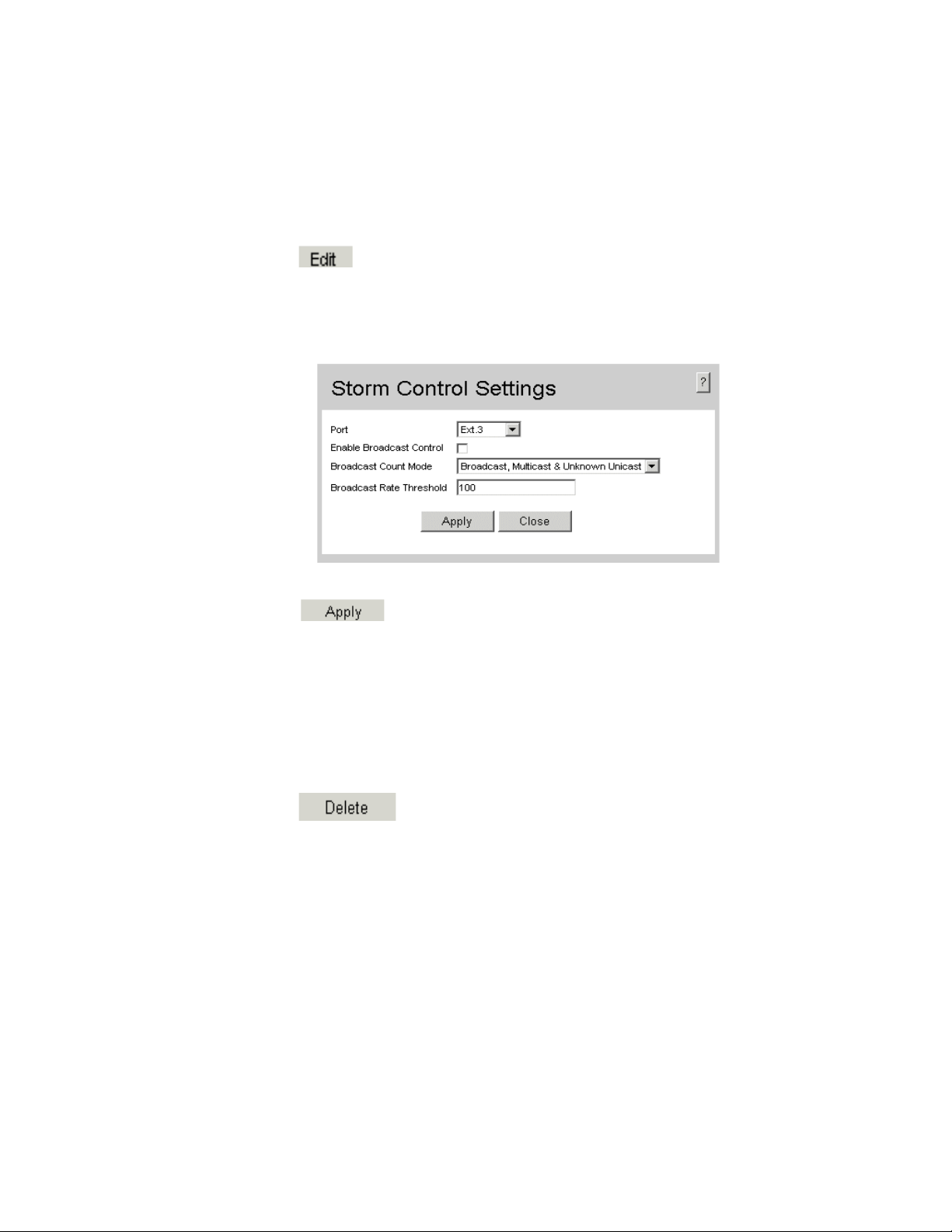
3. Click . A modification page, such as the Storm Control Settings Page
opens:
Figure 5. Storm Control Settings Page
4. Modify the relevant fields.
5. Click . The fields are modified, and the information is saved to the
device.
Deleting Configuration Information
1. Open The Embedded Web Interface page.
2. Select a table row.
3. Select the Delete checkbox.
4. Click . The information is deleted, and the device is updated.
Intel® Gigabit Ethernet Switch AXXSW1GB User Guide 7
Page 21
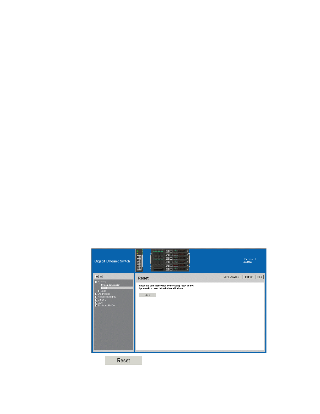
Resetting the Device
The Reset Page enables resetting the device from a remote location.
Note: To prevent the current configuration from being lost, save all changes from the running
configuration file to the startup configuration file before resetting the device.
To reset the device:
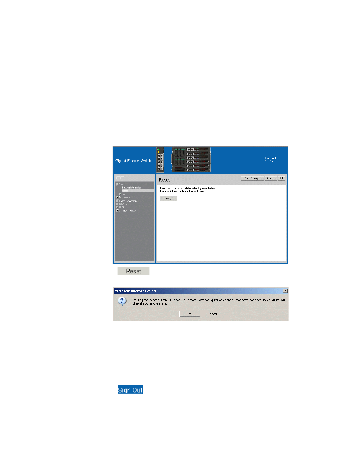
1. Click System > Reset. The Reset Page opens.
Figure 6. Reset Page
2. Click .
3. The device reboots and a confirmation prompt appears.
4. Click OK. The device is reset, and a prompt for a user name and password is
displayed.
5. Enter a user name and password to reconnect to the Web Interface.
Logging Off the Device
1. Click . The Embedded Web Interface Home Page closes.
8 Intel® Gigabit Ethernet Switch AXXSW1GB User Guide
Page 22
2 Managing Device Information
Viewing System Information
The System Information Page contains parameters for configuring general device
information, including the system name, location, and contact, the system MAC Address,
System Object ID, System Up Time, System IP and MAC addresses, and both software
and hardware versions.
To view system information:
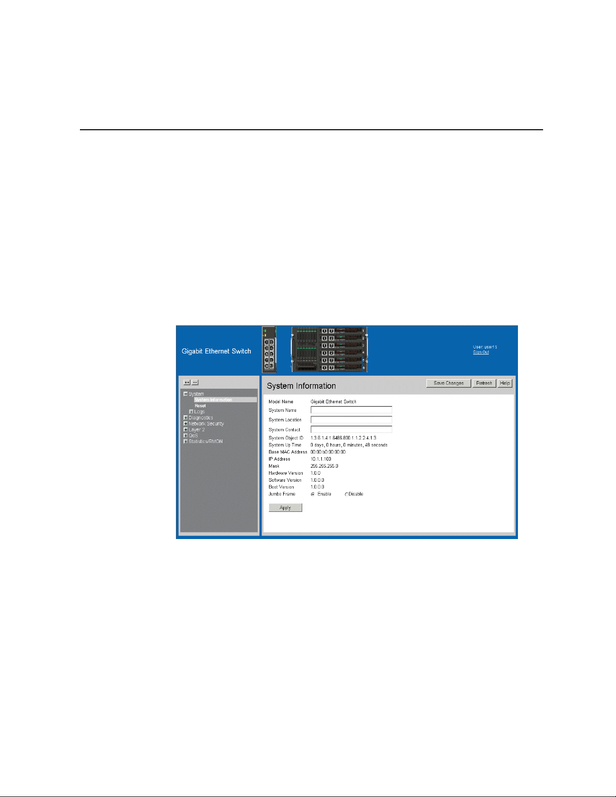
1. Click System > System Information. The System Information Page opens:
Figure 7. System Information Page
The System Information Page contains the following fields:
• Model Name — Displays the device model number and name.
• System Name — Defines the user-defined device name. The field range is 0-160
characters.
• System Location — Defines the location where the system is currently running. The
field range is 0-160 characters.
• System Contact — Defines the name of the contact person. The field range is 0-160
characters.
• System Object ID — Displays the vendor’s authoritative identification of the
network management subsystem contained in the entity.
Intel® Gigabit Ethernet Switch AXXSW1GB User Guide 9
Page 23
• System Up Time — Displays the amount of time since the most recent device reset.
The system time is displayed in the following format: Days, Hours, Minutes, and
Seconds. For example, 41 days, 2 hours, 22 minutes, and 15 seconds.
• Base MAC Address — Displays the device MAC address.
• IP Address — Displays the IP Address assigned to the switch
• Mask — Displays the Mask Address assigned to the switch
• Hardware Version — Displays the installed device hardware version number.
• Software Version — Displays the installed software version number.
• Boot Version — Displays the current boot version running on the device.
• Jumbo Frames — Indicates if Jumbo Frames are enabled on the device. The possible
field values are:
— Enable — Enables Jumbo Frames on the device.
— Disable — Disables Jumbo Frames on the device
Resetting the Device
The Reset Page enables resetting the device from a remote location.
To prevent the current configuration from being lost, save all changes from the running
configuration file to the backup configuration file before resetting the device.
To reset the device:
1. Click System > Reset. The Reset Page opens:
Figure 8. Reset Page
2. Click .
10 Intel® Gigabit Ethernet Switch AXXSW1GB User Guide
The Ethernet switch is reset, and the device is updated.
Page 24

3 Configuring Device Security
This section provides access to security pages that contain fields for setting security
parameters for ports and device management methods. This section contains the following
topics:
• Configuring Traffic Control
• Defining Access Control Lists
Configuring Traffic Control
This section contains information for managing both port security and storm control, and
includes the following topics:
• Enabling Storm Control
• Managing Port Security
Enabling Storm Control
Storm control limits the amount of Broadcast, Multicast and Unknown Unicast frames
accepted and forwarded by the device. When Layer 2 frames are forwarded, Broadcast,
Multicast and Unknown Unicast frames are flooded to all ports on the relevant VLAN.
This occupies bandwidth, and loads all nodes on all ports.
A Packet Storm is a result of an excessive amount of either Broadcast or Multicast or
Unknown Unicast messages simultaneously transmitted across a network by a single port.
Forwarded message responses are heaped onto the network, straining network resources
or causing the network to time out.
Storm control is enabled for all ports by defining the packet type and the rate the packets
are transmitted. The system measures the incoming Broadcast, Multicast or Unknown
Unicast frame rates separately on each port, and discards the frames when the rate exceeds
a user-defined rate.
The Storm Control Page provides fields for configuring packet storm control.
Intel® Gigabit Ethernet Switch AXXSW1GB User Guide 11
Page 25

To enable storm control:
1. Click Network Security > Traffic Control > Storm Control. The Storm Control
Page opens.
Figure 9. Storm Control Page
The Storm Control Page contains the following fields:
• Port — Indicates the port from which storm control is enabled.
• Enable Broadcast Control — Indicates if forwarding Broadcast packet types is
enabled/disabled on the interface. The possible field values are:
— Enable — Enables storm control on the selected port.
— Disable — Disables storm control on the selected port.
• Broadcast Rate Threshold — Indicates the maximum rate (kilobits per second) at
which packets are forwarded. The range is 3,500 - 1,000,000. The default value is
3,500.
• Broadcast Mode — Specifies the Broadcast mode currently enabled on the port. The
possible field values are:
— Broadcast, Multicast, & Unknown Unicast — Counts Broadcast, Multicast, and
Unicast traffic.
— Multicast & Broadcast — Counts Broadcast and Multicast traffic together.
— Broadcast Only — Counts only Broadcast traffic.
12 Intel® Gigabit Ethernet Switch AXXSW1GB User Guide
Page 26
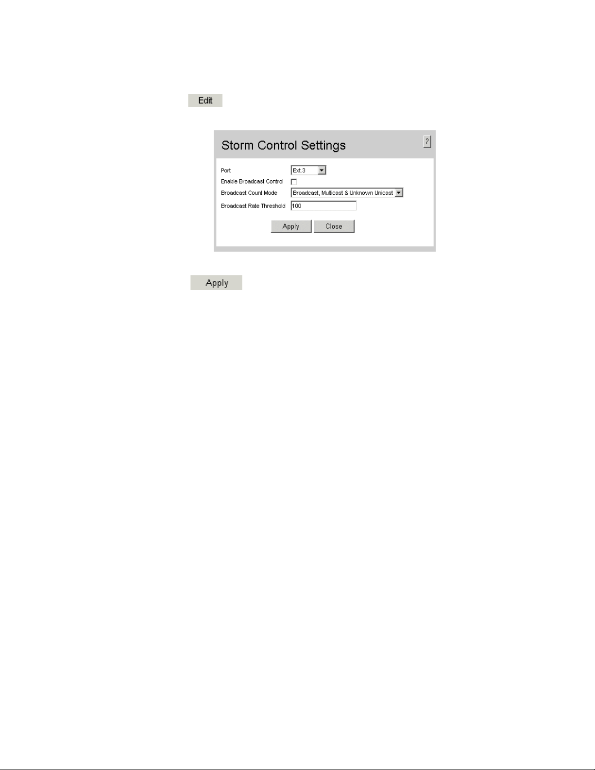
2. Click . The Storm Control Settings Page opens:
Figure 10. Storm Control Settings Page
3. Modify the relevant fields.
4. Click . Storm control is enabled on the device.
Intel® Gigabit Ethernet Switch AXXSW1GB User Guide 13
Page 27
Managing Port Security
Network security can be increased by limiting access on a specific port only to users with
specific MAC addresses. The MAC addresses can be dynamically learned or statically
configured. Locked port security monitors both received and learned packets that are
received on specific ports. Access to the locked port is limited to users with specific MAC
addresses. These addresses are either manually defined on the port, or learned on that port
up to the point when it is locked. When a packet is received on a locked port, and the
packet source MAC address is not tied to that port (either it was learned on a different
port, or it is unknown to the system), the protection mechanism is invoked, and can
provide various options. Unauthorized packets arriving at a locked port are either:
• Forwarded
• Discarded with no trap
• Discarded with a trap
• Shuts down the port
Locked port security also enables storing a list of MAC addresses in the configuration file.
The MAC address list can be restored after the device has been reset.
Disabled ports are activated from the Port Security Page.
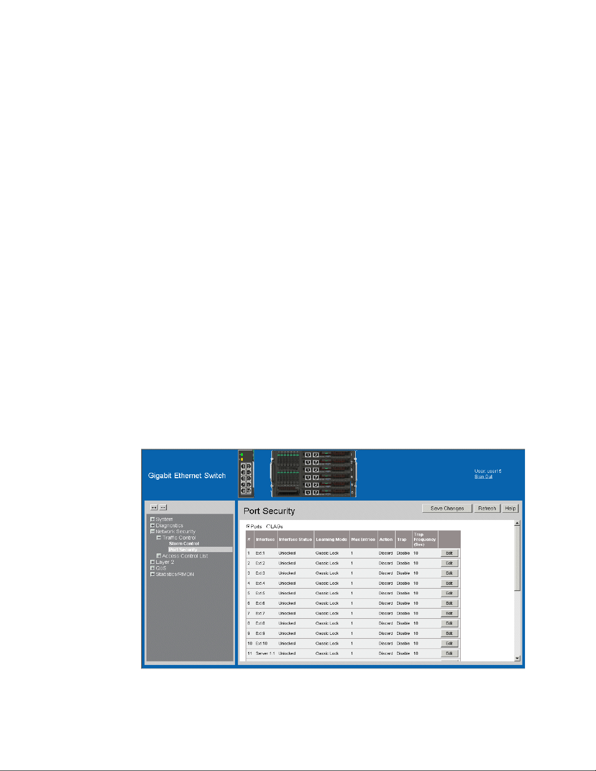
To define port security:
1. Click Network Security > Traffic Control > Port Security. The Port Security
Page opens.
Figure 11. Port Security Page
14 Intel® Gigabit Ethernet Switch AXXSW1GB User Guide
Page 28

The Port Security Page contains the following fields:
• Ports — Indicates the port membership.
• LAGs — Indicates the LAG membership.
• Interface — Displays the port or LAG name.
• Interface Status — Indicates the host status. The possible field values are:
— Unlocked — Indicates that the port is unlocked. This is the default value.
— Locked — Indicates that the port is locked.
• Learning Mode — Defines the locked port type. The Learning Mode field is enabled
only if Locked is selected in the Interface Status field. The possible field values are:
— Classic Lock — Locks the port using the classic lock mechanism. The port is
immediately locked, regardless of the number of addresses that have already
been learned.
— Limited Dynamic Lock — Locks the port by deleting the current dynamic MAC
addresses associated with the port. The port learns up to the maximum addresses
allowed on the port (See the Max Entries field). Both relearning and aging MAC
addresses are enabled.
• Max Entries — Specifies the number of MAC address that can be learned on the
port. The Max Entries field is enabled only if Locked is selected in the Interface
Status field. In addition, the Limited Dynamic Lock mode is selected. The default is 1.
• Action — Indicates the action to be applied to packets arriving on a locked port. The
possible field values are:
—Discard — Discards packets from any unlearned source. This is the default
value.
— Forward — Forwards packets from an unknown source without learning the
MAC address.
— Shutdown — Discards packets from any unlearned source and shuts down the
port. The port remains shut down until reactivated, or until the device is reset.
• Trap — Enables traps when a packet is received on a locked port. The possible field
values are:
— Enable — Enables traps.
— Disable — Disables traps.
• Trap Frequency (Sec) — The amount of time (in seconds) between traps. The range
is between
1–1,000,000. The default value is 10 seconds.
Intel® Gigabit Ethernet Switch AXXSW1GB User Guide 15
Page 29
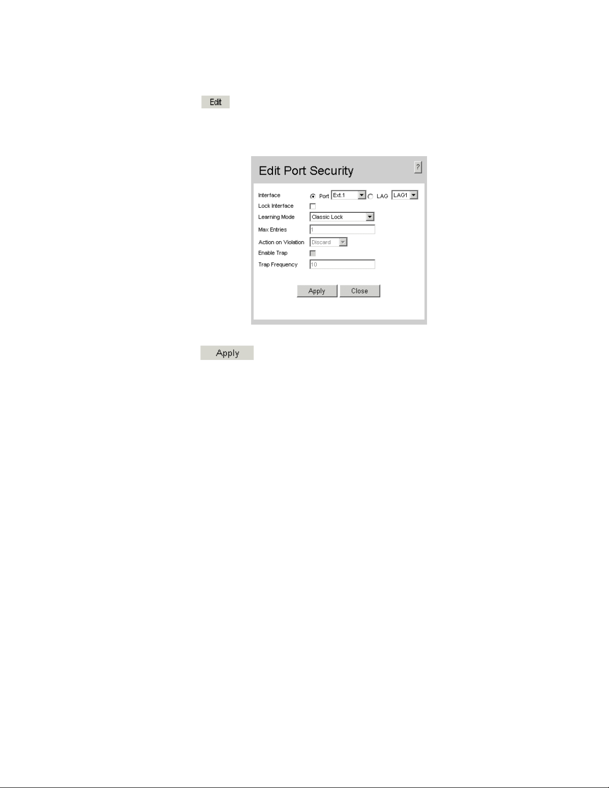
2. Click . The Edit Port Security Settings Page opens:
Figure 12. Edit Port Security Settings Page
3. Modify the relevant fields.
4. Click . The port security settings are defined, and the device is
updated.
16 Intel® Gigabit Ethernet Switch AXXSW1GB User Guide
Page 30

Defining Access Control Lists
Access Control Lists (ACL) allow network managers to define classification actions and
rules for specific ingress ports. Packets entering an ingress port, with an active ACL, are
either admitted or denied entry. If they are denied entry, the user can disable the port.
For example, an ACL rule is defined that states, port number 20 can receive TCP packets,
however, if a UDP packet is received, the packet is dropped. ACLs are composed of
access control entries (ACEs) that are rules that determine traffic classifications.
When configuring ACLs consider the following:
• The maximum number of ACEs/rules per a single ACL are 1018.
• The maximum number of ACEs/rules in all ACLs are 1021.
• The maximum number of ACLs applied to a single interface are 256.
Stages for configuring ACLs:
1. Define an ACL and the initial ACL Rule.
2. Add additional rules to the ACL.
This section contains the following topics:
• Defining MAC Based Access Control Lists
• Defining IP Based Access Control Lists
Intel® Gigabit Ethernet Switch AXXSW1GB User Guide 17
Page 31

Defining MAC Based Access Control Lists
The MAC Based ACL Page allows a MAC-based ACL to be defined. Rules can be added
only if the ACL is not bound to an interface.
To define MAC Based ACLs:
1. Click Network Security > Access Control List > MAC Based ACL. The MAC
Based ACL Page opens:
Figure 13. MAC Based ACL Page
The MAC Based ACL Page contains the following fields:
• ACL Name — Displays the user-defined MAC based ACLs.
• Check box— Selecting the check box, deletes the MAC based ACLs. The possible
field values are:
— Checked — Deletes the selected MAC based ACL.
— Unchecked — Maintains the MAC based ACLs.
• Priority — Indicates the Rule Priority, which determines which rule is matched to a
packet on a first-match basis. The possible field values are 1-2147483647.
• Source MAC Address — Source MAC Address.
— MAC Address — Matches the source MAC Address to which packets are
addressed to the rule.
— Mask — Indicates the source MAC Address wildcard mask. Wildcards are used
to mask all or part of a source MAC Address. Wildcard masks specify which
bits are used and which are ignored. A wildcard mask of FF:FF:FF:FF:FF:FF
18 Intel® Gigabit Ethernet Switch AXXSW1GB User Guide
Page 32

indicates that no bit is important. A wildcard of 00.00.00.00.00.00.00 indicates
that all bits are important. For example, if the source MAC address is
00:AB:22:11:33:00 and the wildcard mask is 00:00:00:00:00:FF, the last two
bits are ignored.
• Destination — Destination MAC Address.
— MAC Address — Matches the destination MAC Address to which packets are
addressed to the rule.
— Mask — Indicates the destination MAC Address wildcard mask. Wildcards are
used to mask all or part of a destination MAC address. Wildcard masks specify
which bits are used and which are ignored. A wildcard mask of FF:FF:FF:FF:FF
indicates that no bit is important. A wildcard mask of 00.00.00.00.00.00
indicates that all bits are important. For example, if the destination MAC
address is E0:00:AB:22:11:33:00 and the wildcard mask is 00:00:00:00:00:FF,
the last two bits are ignored.
• VLAN ID — Matches the packet’s VLAN ID to the rule. The possible field values are
1 to 4093.
• CoS — Classifies traffic based on the CoS tag value.
• CoS Mask — Defines the Cost of Service mask.
• Ether Type — Provides an identifier that differentiates between various types of
protocols.
• Action — Indicates the ACL forwarding action. In addition, the port can be shut
down, a trap can be sent to the network administrator, or packet is assigned rate
limiting restrictions for forwarding. The options are as follows:
— Permit — Forwards packets which meet the ACL criteria.
— Deny — Drops packets which meet the ACL criteria.
— Shutdown — Drops packet that meet the ACL criteria, and disables the port to
which the packet was addressed. Ports are reactivated from the Port
Configuration Page.
Intel® Gigabit Ethernet Switch AXXSW1GB User Guide 19
Page 33

2. Click . The Add MAC Based ACL and First Rule Page opens:
Figure 14. Add MAC Based ACL and First Rule Page
The Add MAC Based ACL and First Rule Page contains the following fields:
• New Rule Priority — Indicates the rule priority, which determines which rule is
matched to a packet on a first match basis.
3. Define the relevant fields.
4. Click . The MAC Based ACLs are defined, and the device is updated.
5. Click . The Add ACL Rule Page opens:
Figure 15. Add ACL Rule Page
6. Define the relevant fields.
7. Click . The ACL rule is defined, and the device is updated.
20 Intel® Gigabit Ethernet Switch AXXSW1GB User Guide
Page 34

To modify a MAC-based rule:
1. Click Network Security > Access Control List > MAC Based ACL. The Edit
Rule Page opens.
2. Click . The Edit Rule Page opens:
Figure 16. Edit Rule Page
3. Modify the relevant fields.
4. Click . The MAC-based rule is modified, and the device is updated.
Intel® Gigabit Ethernet Switch AXXSW1GB User Guide 21
Page 35

Defining IP Based Access Control Lists
Access Control Lists (ACL) allow network managers to define classification actions and
rules for specific ingress ports. Packets entering an ingress port, with an active ACL, are
either admitted or denied entry. If they are denied entry, the user can disable the port.
ACLs are composed of access control entries (ACEs) which are rules that are made of the
filters that determine traffic classifications.
When configuring ACLs consider the following:
• The maximum number of ACEs/rules per a single ACL are 1018.
• The maximum number of ACEs/rules in all ACLs are 1021.
• The maximum number of ACLs applied to a single interface are 256.
The IP Based ACL Page contains information for defining IP Based ACLs and rules.
To define IP Based ACLs:
1. Click Network Security > Access Control List > IP Based ACL. The IP Based
ACL Page opens:
Figure 17. IP Based ACL Page
The IP Based ACL Page contains the following fields:
• ACL Name — Displays the user-defined IP based ACLs.
• Delete — Deletes the IP based ACLs. The possible field values are:
— Checked — Deletes the selected IP based ACL.
— Unchecked — Maintains the IP based ACLs.
• Priority — Indicates the Rule priority that determines which rule is matched to a
packet based on a first-match basis. The possible field value is 1-2147483647.
22 Intel® Gigabit Ethernet Switch AXXSW1GB User Guide
Page 36

• Protocol — Creates an rule based on a specific protocol.
— Select from List — Selects from a protocols list on which rule can be based. The
possible field values are:
ICMP — Internet Control Message Protocol (ICMP). The ICMP allows the
gateway or destination host to communicate with the source host. For
example, to report a processing error.
IGMP — Internet Group Management Protocol (IGMP). Allows hosts to
notify their local switch or router that they want to receive transmissions
assigned to a specific multicast group.
IP — Internet Protocol (IP). Specifies the format of packets and their
addressing method. IP addresses packets and forwards the packets to the
correct port.
TCP — Transmission Control Protocol (TCP). Enables two hosts to
communicate and exchange data streams. TCP guarantees packet delivery,
and guarantees packets are transmitted and received in the order the are sent.
EGP — Exterior Gateway Protocol (EGP). Permits exchanging routing
information between two neighboring gateway hosts in an autonomous
systems network.
IGP — Interior Gateway Protocol (IGP). Allows for routing information
exchange between gateways in an autonomous network.
UDP — User Datagram Protocol (UDP). Communication protocol that
transmits packets but does not guarantee their delivery.
HMP — Host Mapping Protocol (HMP). Collects network information from
various networks hosts. HMP monitors hosts spread over the internet as well
as hosts in a single network.
RDP — Remote Desktop Protocol (RDP). Allows a clients to communicate
with the Terminal Server over the network.
IDRP— Matches the packet to the Inter-Domain Routing Protocol (IDRP).
RVSP — Matches the packet to the ReSerVation Protocol (RSVP).
AH — Authentication Header (AH). Provides source host authentication and
data integrity.
EIGRP — Enhanced Interior Gateway Routing Protocol (EIGRP). Provides
fast convergence, support for variable-length subnet mask, and supports
multiple network layer protocols.
OSPF — The Open Shortest Path First (OSPF) protocol is a link-state,
hierarchical interior gateway protocol (IGP) for network routing Layer Two
(2) Tunneling Protocol, an extension to the PPP protocol that enables ISPs to
operate Virtual Private Networks (VPNs).
IPIP — IP over IP (IPIP). Encapsulates IP packets to create tunnels between
two routers. This ensures that the IPIP tunnel appears as a single interface,
rather than several separate interfaces. IPIP enables tunnel intranets occur the
internet, and provides an alternative to source routing.
PIM — Matches the packet to Protocol Independent Multicast (PIM).
L2TP— Matches the packet to Layer 2 Internet Protocol (L2IP).
ISIS — Intermediate System - Intermediate System (ISIS). Distributes IP
routing information throughout a single Autonomous System in IP networks
Intel® Gigabit Ethernet Switch AXXSW1GB User Guide 23
Page 37

Any — Matches the protocol to any protocol.
— Protocol ID — Adds user-defined protocols by which packets are matched to
the rule. Each protocol has a specific protocol number which is unique. The
possible field range is 0-255.
• Flag Set — Displays the TCP flag that can be triggered.
• ICMP Type — Specifies an ICMP message type for filtering ICMP packets.
• ICMP Code —Specifies an ICMP message code for filtering ICMP packets. ICMP
packets that are filtered by ICMP message type can also be filtered by the ICMP
message code.
• IGMP Type — Displays the IGMP message type. IGMP packets can be filtered by
IGMP message type.
• Source IP Address — Matches the source port IP address to which packets are
addressed to the ACE.
• Source Mask — Defines the source IP address wildcard mask. Wildcard masks
specify which bits are used and which bits are ignored. A wildcard mask of
255.255.255.255 indicates that no bit is important. A wildcard of 0.0.0.0 indicates that
all the bits are important. For example, if the source IP address 149.36.184.198 and
the wildcard mask is 255.36.184.00, the first eight bits of the IP address are ignored,
while the last eight bits are used.
• Destination IP Address — Matches the destination IP address to which packets are
addressed to the rule.
• Destination Mask —Indicates the destination IP Address wildcard mask. Wildcards
are used to mask all or part of a destination IP Address. Masks specify which bits are
used and which bits are ignored. A mask of 255.255.255.255 indicates that no bit is
important. A wildcard of 00.00.00.00 indicates that all the bits are not important. For
example, if the destination IP address is 149.36.184.198 and the wildcard mask is
255.255.255.00, the last three digits in the IP address are checked while the first 3 sets
are ignored.
• Source Port — Defines the TCP/UDP source port to which the rule is matched. This
field is active only if 800/6-TCP or 800/17-UDP are selected in the Select from List
drop-down menu. The possible field range is 0 - 65535.
• Destination Port — Defines the TCP/UDP destination port. This field is active only
if 800/6-TCP or 800/17-UDP are selected in the Select from List drop-down menu.
The possible field range is 0 - 65535.
• DSCP — Matches the destination port IP address to which packets are addressed to
the rule.
• IP - Prec. — Defines the destination IP address wildcard mask. Select either Match
DSCP or Match IP Precedence:
— Match DSCP — Matches the packet DSCP value to the rule. Either the DSCP
value or the IP Precedence value is used to match packets to ACLs. The possible
field range is 0-63.
— Match IP Precedence — Matches the packet IP Precedence value to the rule.
Either the DSCP value or the IP Precedence value is used to match packets to
ACLs. The possible field range is 0-7.
24 Intel® Gigabit Ethernet Switch AXXSW1GB User Guide
Page 38

• Action — Indicates the ACL forwarding action. In addition, the port can be shut
down, a trap can be sent to the network administrator, or packet is assigned rate
limiting restrictions for forwarding. The options are as follows:
— Permit — Forwards packets which meet the ACL criteria.
— Deny — Drops packets which meet the ACL criteria.
— Shutdown — Drops packet that meet the ACL criteria, and disables the port to
which the packet was addressed. Ports are reactivated from the Port
Configuration Page.
2. Click . The Add IP Based ACL and First Rule Page opens:
Figure 18. Add IP Based ACL and First Rule Page
3. Define the relevant fields.
4. Click . The IP based ACL and first rule are defined, and the device is
updated.
Intel® Gigabit Ethernet Switch AXXSW1GB User Guide 25
Page 39

To add an IP based Rule to the ACL:
1. Click Network Security > Access Control List > IP Based ACL. The IP Based
ACL Page opens.
2. Click . The Add IP Based Rule Page opens:
Figure 19. Add IP Based Rule Page
3. Define the relevant fields.
4. Click . The IP based rules are defined, and the device is updated.
26 Intel® Gigabit Ethernet Switch AXXSW1GB User Guide
Page 40

To modify an IP based Rule:
1. Click Network Security > Access Control List > IP Based ACL. The IP Based
ACL Page opens.
2. Select an ACL.
3. Click . The Edit Rule Page opens:
Figure 20. Edit Rule Page
4. Modify the relevant fields.
5. Click . The IP based rule is defined, and the device is updated.
Intel® Gigabit Ethernet Switch AXXSW1GB User Guide 27
Page 41

Binding Device Security ACLs
When an ACL is bound to an interface, all the rules that have been defined are applied to the
selected interface.
interface that do not match the ACL are matched to the default rule, which is Drop
unmatched packets.
To bind ACLs to interfaces:
1. Click Network Security > Access Control List > ACL Binding. The ACL
Binding Page opens:
Whenever an ACL is assigned on a port or LAG, flows from that ingress
Figure 21. ACL Binding Page
The ACL Binding Page contains the following fields:
• Check Box — Selecting the check box, selects the ACL binding entry. The possible
field values are:
— Checked — Selects the MAC based ACL.
— Unchecked — Maintains the MAC based ACLs.
• Ports — Indicates the port membership.
• LAGs — Indicates the LAG membership.
• Interface — Indicates the interface to which the ACL is bound.
• ACL Name — Indicates the ACL which is bound the interface.
28 Intel® Gigabit Ethernet Switch AXXSW1GB User Guide
Page 42
2. Select an interface.
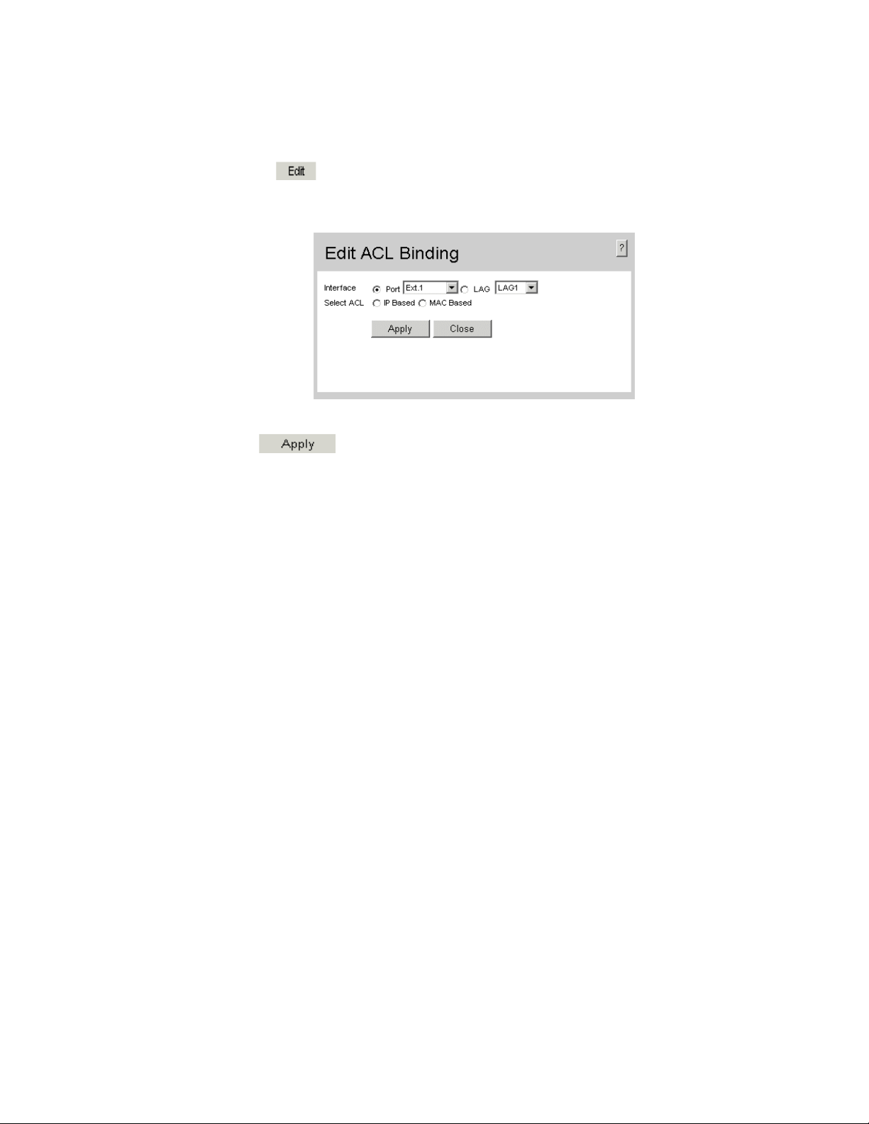
3. Click . The Edit ACL Binding Page opens:
Figure 22. Edit ACL Binding Page
4. Define the relevant fields.
• Click . The ACL is bound the interface, and the device is updated.
Intel® Gigabit Ethernet Switch AXXSW1GB User Guide 29
Page 43

30 Intel® Gigabit Ethernet Switch AXXSW1GB User Guide
Page 44

4 Configuring Ports
The Port Configuration Page contains fields for defining port parameters.
To define port parameters:
1. Click Layer 2 > Interface > Port Configuration. The Port Configuration Page
opens.
Figure 23. Port Configuration Page
The Port Configuration Page contains the following fields:
• Interface — Displays the port number.
• PortType — Displays the port type. The possible field values are:
— 1000M-Copper — Indicates the port has a copper port connection.
• Port Status — Indicates whether the port is currently operational or non-operational.
The possible field values are:
— Up — Indicates the port is currently operating.
— Down — Indicates the port is currently not operating.
• Port Speed — Displays the configured rate for the port. The port type determines
what speed setting options are available. Port speeds can only be configured when
auto negotiation is disabled. The possible field values are:
— 10 — Indicates the port is currently operating at 10 Mbps.
— 100 — Indicates the port is currently operating at 100 Mbps.
— 1000 — Indicates the port is currently operating at 1000 Mbps.
— 10G — Indicates the port is currently operating at 10 Gbps.
Intel® Gigabit Ethernet Switch AXXSW1GB User Guide 31
Page 45

• Duplex Mode — Displays the port duplex mode. This field is configurable only when
auto negotiation is disabled, and the port speed is set to 10M or 100M. This field
cannot be configured on LAGs. The possible field values are:
— Full — The interface supports transmission between the device and its link
partner in both directions simultaneously.
— Half — The interface supports transmission between the device and the client in
only one direction at a time.
• Auto Negotiation — Displays the auto negotiation status on the port. Auto
negotiation is a protocol between two link partners that enables a port to advertise its
transmission rate, duplex mode, and flow control abilities to its partner.
• Advertisement — Defines the auto negotiation setting the port advertises. The
possible field values are:
— Max Capability — Indicates that all port speeds and duplex mode settings are
accepted.
— 10 Half — Indicates that the port advertises for a 10 Mbps speed port and half
duplex mode setting.
— 10 Full — Indicates that the port advertises for a 10 Mbps speed port and full
duplex mode setting.
— 100 Half — Indicates that the port advertises for a 100 Mbps speed port and half
duplex mode setting.
— 100 Full — Indicates that the port advertises for a 100 Mbps speed port and full
duplex mode setting.
— 1000 Full — Indicates that the port advertises for a 1000 Mbps speed port and
full duplex mode setting.
• Back Pressure — Displays the back pressure mode on the Port. Back pressure mode
is used with half duplex mode to disable ports from receiving messages.
• Flow Control — Displays the flow control status on the port. Operates when the port
is in full duplex mode. The possible field values are:
— Enable — Enables the flow control.
— Disable — Disables the flow control.
— Auto-Negotiation — Detects the flow control and automatically configures the
highest performance mode.
• MDI/MDIX — Displays the MDI/MDIX status on the port. Hubs and switches are
deliberately wired opposite the way end stations are wired, so that when a hub or
switch is connected to an end station, a straight through Ethernet cable can be used,
and the pairs are matched up properly. When two hubs or switches are connected to
each other, or two end stations are connected to each other, a crossover cable is used
to ensure that the correct pairs are connected. The possible field values are:
— MDIX (Media Dependent Interface with Crossover) — Use for hubs and
switches.
— MDI (Media Dependent Interface) — Use for end stations.
— AUTO — Use to automatically detect the cable type.
32 Intel® Gigabit Ethernet Switch AXXSW1GB User Guide
Page 46

• PVE — Defines the port as a Private VLAN Edge (PVE) port. PVE is configured on
the port level and indicates that all traffic received on the port will be redirected to an
uplink port. The PVE associated Uplinks ports are defined on the
Settings Page.
Port Configuration
• LAG — Indicates whether the port is part of a Link Aggregation Group (LAG).
2. Define the relevant fields.
3. Click . The port configuration settings are defined, and the device is
updated.
To modify the port configuration:
1. Click . The Port Configuration Settings Page opens:
Figure 24. Port Configuration Settings Page
In addition the fields appearing on the Port Configuration Page, the Port Configuration
Settings Page contains the following fields:
• Description — Provides a user-defined port description.
• Admin Status — Displays the port operational status. Changes to the port state are
active only after the device is reset. The possible field values are:
— Up — Indicates that the port is currently operating.
— Down — Indicates that the port is currently not operating.
• Current Port Status — Displays the current status of the port.
• Reactivate Suspended Port — Reactivates a port if the port has been disabled
through the locked port security option.
Intel® Gigabit Ethernet Switch AXXSW1GB User Guide 33
Page 47

• Operational Status — Indicates the port operational status. Possible field values are:
— Suspended — Indicates the port is currently active, and is not receiving or
transmitting traffic.
— Active — Indicates the port is currently active and is receiving and transmitting
traffic.
— Disable — Indicates the port is currently disabled, and is not receiving or
transmitting traffic.
• Admin Speed — Displays the configured rate for the port. The port type determines
what speed setting options are available.
• Current Port Speed — Displays the actual synchronized port speed (bps).
• Admin Duplex — Indicates port duplex mode can be either Full or Half. Full
indicates that the interface supports transmission between the device and its link
partner in both directions simultaneously. Half indicates that the interface supports
transmission between the device and the client in only one direction at a time.
• Current Duplex Mode — Displays the currently configured port duplex mode.
• Current Duplex Mode — Displays the current Duplex Mode.
• Current Auto Negotiation — Displays the current Auto Negotiation Mode.
• Admin Advertisement — Defines the auto-negotiation setting the port advertises.
The possible field values are:
— Max Capability — Indicates that all port speeds and Duplex mode settings are
accepted.
— 10 Full — Indicates that the port advertises for a 10 mbps speed port and full
duplex mode setting.
— 100 Full — Indicates that the port advertises for a 100 mbps speed port and full
duplex mode setting.
— 1000 Full — Indicates that the port advertises for a 1000 mbps speed port and
full duplex mode setting.
• Current Advertisement — The port advertises its speed to its neighbor port to start
the negotiation
advertisement field.
process. The possible field values are those specified in the Admin
• Neighbor Advertisement — Indicates the neighboring port’s advertisement settings.
The field values are identical to the Admin Advertisement field values.
• Current Back Pressure — Displays the current Back Pressure setting.
• Current Flow Control — Displays the current Flow Control setting.
• Current MDI/MDIX — Displays the current MDI/MDIX setting.Define the
relevant fields.
2. Click . The port configuration settings are defined, and the device is
updated.
34 Intel® Gigabit Ethernet Switch AXXSW1GB User Guide
Page 48

5 Aggregating Ports
Link Aggregation optimizes port usage by linking a group of ports together to form a
single LAG. Aggregating ports multiplies the bandwidth between the devices, increases
port flexibility, and provides link redundancy.
The device supports both static LAGs and Link Aggregation Control Protocol (LACP)
LAGs. LACP LAGs negotiate aggregating port links with other LACP ports located on a
different device. If the other device ports are also LACP ports, the devices establish a
LAG between them. Ensure the following:
• All ports within a LAG must be the same media type.
• A VLAN is not configured on the port.
• The port is not assigned to a different LAG.
• The port is in full-duplex mode.
• All ports in the LAG have the same ingress filtering and tagged modes.
• All ports in the LAG have the same flow control modes.
• All ports in the LAG have the same priority.
• All ports in the LAG have the same transceiver type.
• The device supports up to 10 LAGs, and eight ports in each LAG.
• Ports can be configured as LACP ports only if the ports are not part of a previously
configured LAG.
• Ports added to a LAG lose their individual port configuration. When ports are
removed from the LAG, the original port configuration is applied to the ports.
• LAGs can be configured only on external ports.
This section contains the following topics:
• Configuring LAGs
• Defining LAG Members
• Configuring LACP
• Configuring Virtual Trunk Group Failover
Intel® Gigabit Ethernet Switch AXXSW1GB User Guide 35
Page 49

Configuring LAGs
The LAG Configuration Page contains information for configured LAGs.
To view LAG information:
1. Click Layer 2 > Interface > LAG Configuration. The LAG Configuration Page
opens:
Figure 25. LAG Configuration Page
The LAG Configuration Page contains the following fields:
• LAG — Indicates the LAG for which the information is displayed.
• Description — Provides a user-defined LAG description.
• Type — Displays the port types included in the LAG.
• Status — Indicates if traffic forwarding via the LAG is enabled. The possible field
values are:
— Up — Indicates that the LAG is currently forwarding network traffic.
— Down — Indicates that the LAG is not currently forwarding network traffic.
• Speed — Displays the LAG speed.
• Auto Negotiation — Indicates if auto-negotiation is enabled on the LAG. The
possible field values are:
— Enable — Indicates that auto-negotiation is enabled on the LAG.
— Disable — Indicates that auto-negotiation is disable on the LAG.
36 Intel® Gigabit Ethernet Switch AXXSW1GB User Guide
Page 50

• Flow Control — Indicates if flow control auto-negotiation is enabled on the LAG.
The possible field values are:
— Enable — Indicates that flow control is enabled on the LAG.
— Disable — Indicates that flow control is disable on the LAG.
— Auto Negotiation — Detects the flow control and automatically configures the
highest performance mode.
2. Define the relevant fields.
3. Click . The LAG configuration settings are saved, and the device is
updated.
To modify the LAG configuration:
1. Click . The LAG Configuration Settings Page opens:
Figure 26. LAG Configuration Settings Page
Intel® Gigabit Ethernet Switch AXXSW1GB User Guide 37
Page 51

In addition the fields appearing on the LAG Configuration Page, the LAG Configuration
Settings Page contains the following fields:
• Admin Status — Displays the LAG operational status. Changes to the LAG state
are active only after the device is reset. The possible field values are:
— Up — Indicates that the LAG is currently operating.
— Down — Indicates that the LAG is currently not operating.
• Current Status — Displays the current status of the LAG.
• Reactivate Suspended — Reactivates a port if the port has been disabled through the
locked port security option.
• Operational Status — Indicates the port operational status. Possible field values are:
— Suspended — The port is currently active, and is not receiving or transmitting
traffic.
— Active — The port is currently active and is receiving and transmitting traffic.
— Disable — The port is currently disabled, and is not receiving or transmitting
traffic.
• Admin Auto Negotiation — Enables or disables Auto Negotiation on the LAG.
Auto-negotiation is a protocol between two link partners that enables a LAG to
advertise its transmission rate, duplex mode and flow control (the flow control default
is disabled) abilities to its partner.
• Admin Advertisement — Defines the auto-negotiation setting the port advertises.
The possible field values are:
— Max Capability — Indicates that all port speeds and Duplex mode settings are
accepted.
— 10 Full — Indicates that the port advertises for a 10 mbps speed port and full
duplex mode setting.
— 100 Full — Indicates that the port advertises for a 100 mbps speed port and full
duplex mode setting.
— 1000 Full — Indicates that the port advertises for a 1000 mbps speed port and
full duplex mode setting.
• Current Advertisement — The port advertises its speed to its neighbor port to start
the negotiation
advertisement field.
process. The possible field values are those specified in the Admin
• Neighbor Advertisement — Indicates the neighboring port’s advertisement settings.
The field values are identical to the Admin Advertisement field values.
• Admin Speed — The configured rate for the port. The port type determines what
speed setting options are available. Admin speed can only be designated when the
Admin Auto Negotiation field is disabled.
• Current Speed — The actual synchronized port speed (bps).
• Admin Flow Control — Enables/disables flow control, or enables the auto
negotiation of flow control on the LAG. Flow Control mode is effective on the ports
operating in Full Duplex in the LAG.
38 Intel® Gigabit Ethernet Switch AXXSW1GB User Guide
Page 52

• Current Flow Control — The current Flow Control setting.
2. Define the relevant fields.
3. Click . The LAG configuration is saved, and the device is updated.
Intel® Gigabit Ethernet Switch AXXSW1GB User Guide 39
Page 53

Defining LAG Members
The LAG Membership Page contains fields for configuring parameters for configured
LAGs. The device supports up to eight ports per LAG, and ten LAGs per system. LAGs
can be configured only on external ports.
To define LAG parameters:
1. Click Layer 2 > Interface > LAG Membership. The LAG Membership Page
opens.
Figure 27. LAG Membership Page
The LAG Membership Page contains the following fields:
• LAG — Displays the ports which can be assigned to the LAG.
• Name — Indicates the LAG name.
• Link State — Displays the status of the link.
• Member — Displays the ports which are currently configured to the LAG.
2. Define the relevant fields.
3. Click . The LAG membership settings are saved, and the device is
updated.
40 Intel® Gigabit Ethernet Switch AXXSW1GB User Guide
Page 54

To modify the LAG membership:
1. Click . The LAG Membership Settings Page opens:
Figure 28. LAG Membership Settings Page
In addition the fields appearing on the LAG Membership Page, the LAG Membership
Settings Page contains the following fields:
• LACP — Enables LACP on the selected LAG.
2. Define the relevant fields.
3. Click . The LAG configuration is saved, and the device is updated.
Intel® Gigabit Ethernet Switch AXXSW1GB User Guide 41
Page 55

Configuring LACP
LAG ports can contain different media types if the ports are operating at the same speed.
Aggregated links can be set up manually or automatically established by enabling LACP
on the relevant links. Aggregate ports can be linked into link-aggregation port-groups.
Each group is comprised of ports with the same speed. The LACP Parameters Page
contains fields for configuring LACP LAGs.
To configure LACP for LAGs:
1. Click Layer 2 > Interface > LACP Parameters. The LACP Parameters Page
opens:
Figure 29. LACP Parameters Page
The LACP Parameters Page contains the following fields:
• LACP System Priority — Specifies system priority value. The field range is 1-
65535. The field default is 1.
• Port — Displays the port number to which timeout and priority values are assigned.
• Port-Priority — Displays the LACP priority value for the port. The field range is 1-
65535. The field default is 1.
• LACP Timeout — Displays the administrative LACP timeout. The possible field
values are:
— Long — Specifies the long timeout value.
— Short — Specifies the short timeout value.
42 Intel® Gigabit Ethernet Switch AXXSW1GB User Guide
Page 56

2. Define the relevant fields.
3. Click . The LACP parameters are saved, and the device is updated.
To modify the LACP parameters:
1. Click . The LACP Parameters Settings Page opens:
Figure 30. LACP Parameters Settings Page
2. Modify the relevant fields.
3. Click . The LACP parameters are saved, and the device is updated.
Intel® Gigabit Ethernet Switch AXXSW1GB User Guide 43
Page 57

Configuring Virtual Trunk Group Failover
The Trunk Group Fail Over Page enables a network administrator to define a Virtual
Trunk Group Failover feature. The Trunk Group Failover increases network stability by
ensuring that if a trunk group fails, a different trunk begins to forward the failed trunk’s
traffic. A Virtual Trunk Group Failover is comprised of user defined port groups that
include:
• Uplink Ports — Connects the switch and external network to the associated internal
ports and server NIC.
• Associated Ports — Associated with an Uplink port. Uplinks ports forward host
traffic associated ports to the external network. Although an associated port typically
connects to a Device. External switch ports can also be an Associated port. For
example, a server connected to an external switch port as well as to a dependent group
of ports on an Uplink port that forwards traffic to the external network.
Ensure the following when configuring Virtual Trunk Groups:
• The minimum number of Virtual Trunk Groups is one, whereas the maximum is 12.
• A port cannot be a member of more than one Virtual Trunk Group.
• Virtual Trunk Group Failover is globally enabled.
• The Virtual Trunk Group Failover feature cannot be defined on LAGs. However,
individual ports within a LAG can be added to a Virtual Trunk Group.
• One Virtual Trunk group can have one or more Uplink ports, and one or more
Associated ports.
• Only one Uplink port within the Virtual Trunk Group is required to go up in order for
all the associated ports to go up.
• The Associated ports are deactivated within 500ms from the time that the last Uplink
port in the Virtual Trunk group fails. The Associated ports reactivate within 500ms
whenever a single Uplink port within the group is restored.
• Before the administrator shuts downs an Associated port, the administrator must
exclude the Associated port from any Virtual Failover group.
• The Associated ports which have been shut down administratively cannot be added to
any failover group by the administrator.
• Failover groups can be configured any time regardless of the feature state.
• When Virtual Trunk Group Failover is disabled, all Associated ports disabled by the
Virtual Trunk Group Failover feature are re-enabled.
• When Virtual Trunk Group Failover is enabled, all configured failover groups are
scanned to update the Associated port status.
• A log message is generated and sent to the system log and stored when an Associated
port goes UP or Down.
44 Intel® Gigabit Ethernet Switch AXXSW1GB User Guide
Page 58

To configure Trunk Group Failover:
1. Click Layer 2 > Interface > Trunk Group Fail Over. The Trunk Group Fail Over
Page opens:
Figure 31. Trunk Group Fail Over Page
The Trunk Group Fail Over Page contains the following fields:
• Group Failover Status — Enables the Trunk Group Failover feature on the device.
The possible field values are:
— Enable — Enables Trunk Group Failover on the device.
— Disable — Disables Trunk Group Failover on the device.
• Group — Displays the Trunk Group number.
• Group State — Indicates the Trunk Group state. The possible field values are:
— Up — Indicates the group state is active.
— Down — Indicates the group state is inactive.
• Port — Displays the port added to the specific Trunk Group.
• Type — Displays the port type. The possible field values are:
— Uplink — Ports that connect the switch and external network to the associated
internal ports and server NIC.
— Associated — Ports that are associated with an Uplink port.
• Port State — Indicates the port state within the Trunk Group. The possible field
values are:
— Up — Indicates the port is in the Up state.
— Down — Indicates the port is in the Down state.
Intel® Gigabit Ethernet Switch AXXSW1GB User Guide 45
Page 59
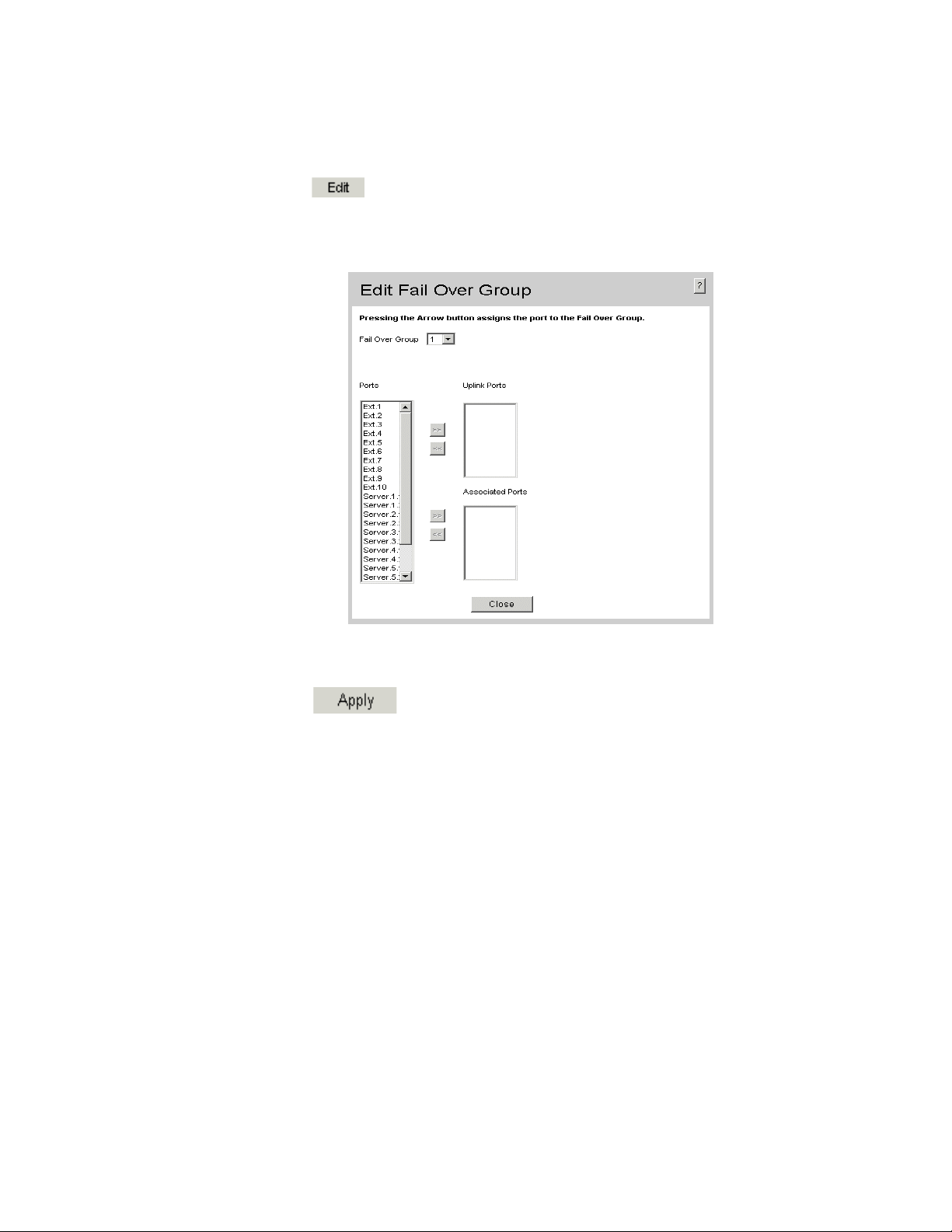
To modify the Fail Over Group:
1. Click . The Edit Fail Over Group Page opens:
Figure 32. Edit Fail Over Group Page
2. Select a Fail Over Group to be defined.
3. Define the Ext. or Server ports as a Uplink or Associated port.
4. Click . The Group Fail Over groups are defined, and the device is
updated.
46 Intel® Gigabit Ethernet Switch AXXSW1GB User Guide
Page 60

6 Configuring VLANs
VLANs are logical subgroups with a Local Area Network (LAN) which combine user
stations and network devices into a single unit, regardless of the physical LAN segment to
which they are attached. VLANs allow network traffic to flow more efficiently within
subgroups. VLANs use software to reduce the amount of time it takes for network
changes, additions, and moves to be implemented.
VLANs have no minimum number of ports since they are software-based and not defined
by physical attributes.
VLANs function at Layer 2. Since VLANs isolate traffic within the VLAN, a Layer 3
router working at a protocol level is required to allow traffic flow between VLANs. Layer
3 routers identify segments and coordinate with VLANs. VLANs are Broadcast and
Multicast domains. Broadcast and Multicast traffic is transmitted only in the VLAN in
which the traffic is generated.
VLAN tagging provides a method of transferring VLAN information between VLAN
groups. VLAN tagging attaches a 4-byte tag to packet headers. The VLAN tag indicates to
which VLAN the packets belong. VLAN tags are attached to the VLAN by either the end
station or the network device. VLAN tags also contain VLAN network priority
information.
Combining VLANs and Generic Attribute Registration Protocol (GARP) allows network
managers to define network nodes into Broadcast domains.
This section contains the following topics:
• Defining VLAN Properties
• Defining VLAN Membership
• Defining VLAN Interface Settings
• Configuring GARP
Intel® Gigabit Ethernet Switch AXXSW1GB User Guide 47
Page 61

Defining VLAN Properties
The VLAN Properties Page provides information and global parameters for configuring
and working with VLANs.
To define VLAN properties:
1. Click Layer 2 > VLAN > Properties. The VLAN Properties Page opens.
Figure 33. VLAN Properties Page
The VLAN Properties Page contains the following fields:
• Delete — Deletes VLANs. The possible field values are:
— Checked — Deletes the selected VLAN.
— Unchecked — Maintains VLANs.
• VLAN ID — Displays the VLAN ID.
• VLAN Name — Displays the user-defined VLAN name.
• Type — Displays the VLAN type. The possible field values are:
— Dynamic — Indicates the VLAN was dynamically created through GARP.
— Static — Indicates the VLAN is user-defined.
— Default — Indicates the VLAN is the default VLAN.
48 Intel® Gigabit Ethernet Switch AXXSW1GB User Guide
Page 62

• Back — Allows you to view the previous page in a table.
• Next — Allows you to view the next page in a table when there are more than 20
entries.
2. Click . The Add VLAN Page opens:
Figure 34. Add VLAN Page
3. Define the relevant fields.
4. Click . The VLAN ID is defined, and the device is updated.
To modify the VLAN ID:
1. Click Layer 2 > VLAN > Properties. The VLAN Properties Page opens.
2. Click . The VLAN Settings Page opens:
Figure 35. VLAN Settings Page
3. Modify the relevant fields.
4. Click . The VLAN Name is defined, and the device is updated.
Intel® Gigabit Ethernet Switch AXXSW1GB User Guide 49
Page 63
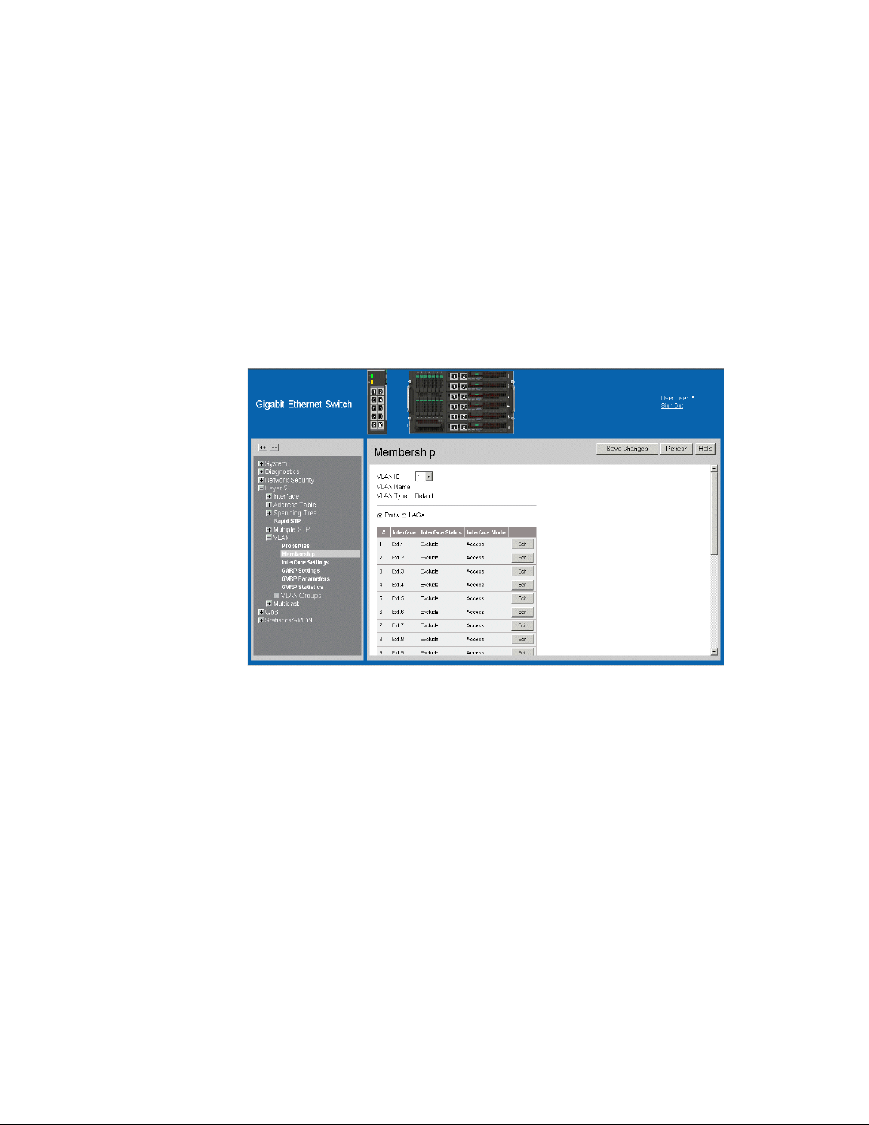
Defining VLAN Membership
The VLAN Membership Page contains a table that maps VLAN parameters to ports/
LAGs. Interfaces are assigned VLAN membership by toggling through the Port Control
settings.
To define VLAN membership:
1. Click Layer 2 > VLAN > Membership. The VLAN Membership Page opens.
Figure 36. VLAN Membership Page
The VLAN Membership Page contains the following fields:
• VLAN ID — Displays the user-defined VLAN ID.
• VLAN Name — Displays the name of the VLAN
• VLAN Type — Indicates the VLAN type. The possible field values are:
— Dynamic — Indicates the VLAN was dynamically created through GARP.
— Static — Indicates the VLAN is user-defined.
— Default — Indicates the VLAN is the default VLAN.
• Ports — Indicates the port membership.
• LAGs — Indicates the LAG membership.
• Interface — Displays the VLAN interfaces.
50 Intel® Gigabit Ethernet Switch AXXSW1GB User Guide
Page 64

• Interface Status — Indicates the port status. The possible field values are:
—Excluded — Excludes the interface from the VLAN. However, the interface can
be added to the VLAN through GARP.
— Forbidden — Denies the interface VLAN membership, even if GARP indicates
the port is to be added.
— Tag ge d — Indicates the interface is a tagged member of a VLAN. All packets
forwarded by the interface are tagged. The packets contain VLAN information.
— Untagged — Indicates the interface is an untagged VLAN member. Packets
forwarded by the interface are untagged.
• Interface Mode — Displays the interface mode. The possible field values are:
— General — Indicates the port belongs to VLANs, and each VLAN is user-
defined as tagged or untagged (full IEEE802.1q mode). The is the default value.
— Trunk — Indicates the port belongs to VLANs in which all VLANs are tagged,
except for one VLAN that can be untagged.
— Access — Indicates a port belongs to a single untagged VLAN. When a port is in
Access mode, the packet types which are accepted on the port cannot be
designated. Ingress filtering cannot be enabled or disabled on an access port.
2. Define the relevant fields.
3. Click . The VLAN membership is defined, and the device is updated.
Intel® Gigabit Ethernet Switch AXXSW1GB User Guide 51
Page 65

To modify the VLAN membership:
1. Click . The Edit VLAN Membership Page opens:
Figure 37. Edit VLAN Membership Page
2. Modify the relevant fields.
3. Click . The VLAN membership is modified
52 Intel® Gigabit Ethernet Switch AXXSW1GB User Guide
Page 66

Defining VLAN Interface Settings
The Interface Settings Page contains fields for managing ports/LAGs that are part of a
VLAN. The Port Default VLAN ID (PVID) is configured on the Interface Settings Page.
All untagged packets arriving at the device are tagged with the port PVID.
To define VLAN interfaces:
1. Click Layer 2 > VLAN > Interface Settings. The Interface Settings Page opens.
Figure 38. Interface Settings Page
The Interface Settings Page contains the following fields:
• Ports — Indicates the port membership.
• LAGs — Indicates the LAG membership.
• Interface — Displays the interface number included in the VLAN.
• Interface VLAN Mode — Displays the interface mode. The possible values are:
— General — Indicates the interface belongs to VLANs, and each VLAN is user-
defined as tagged or untagged (full IEEE802.1q mode).
— Access — Indicates a interface belongs to a single untagged VLAN. When an
interface is in Access mode, the packet types which are accepted on the port
Intel® Gigabit Ethernet Switch AXXSW1GB User Guide 53
Page 67

cannot be designated. Ingress filtering cannot be enabled or disabled on an
access port.
— Trunk — Indicates the interface belongs to VLANs in which all VLANs are
tagged, except for one VLAN that can be untagged.
• PVID — Assigns a VLAN ID to untagged packets. The possible values are 1-4094
except VLAN 4080. VLAN 4095 is defined as per standard and industry practice as
the Discard VLAN. Packets classified to the Discard VLAN are dropped.
• Frame Type — Specifies the packet type accepted on the interface. The possible field
values are:
— Admit All — Both tagged and untagged packets are accepted on the interface.
— Admit Tag Only — Only tagged packets are accepted on the interface.
• Ingress Filtering — Indicates whether ingress filtering is enabled on the interface.
The possible field values are:
— Enable — Enables ingress filtering on the interface. Ingress filtering discards
packets that are defined to VLANs of which the specific port is not a member.
— Disable — Disables ingress filtering on the interface.
• Reserved VLAN — Indicates the VLAN selected by the user to be the reserved
VLAN if not in use by the system.
54 Intel® Gigabit Ethernet Switch AXXSW1GB User Guide
Page 68
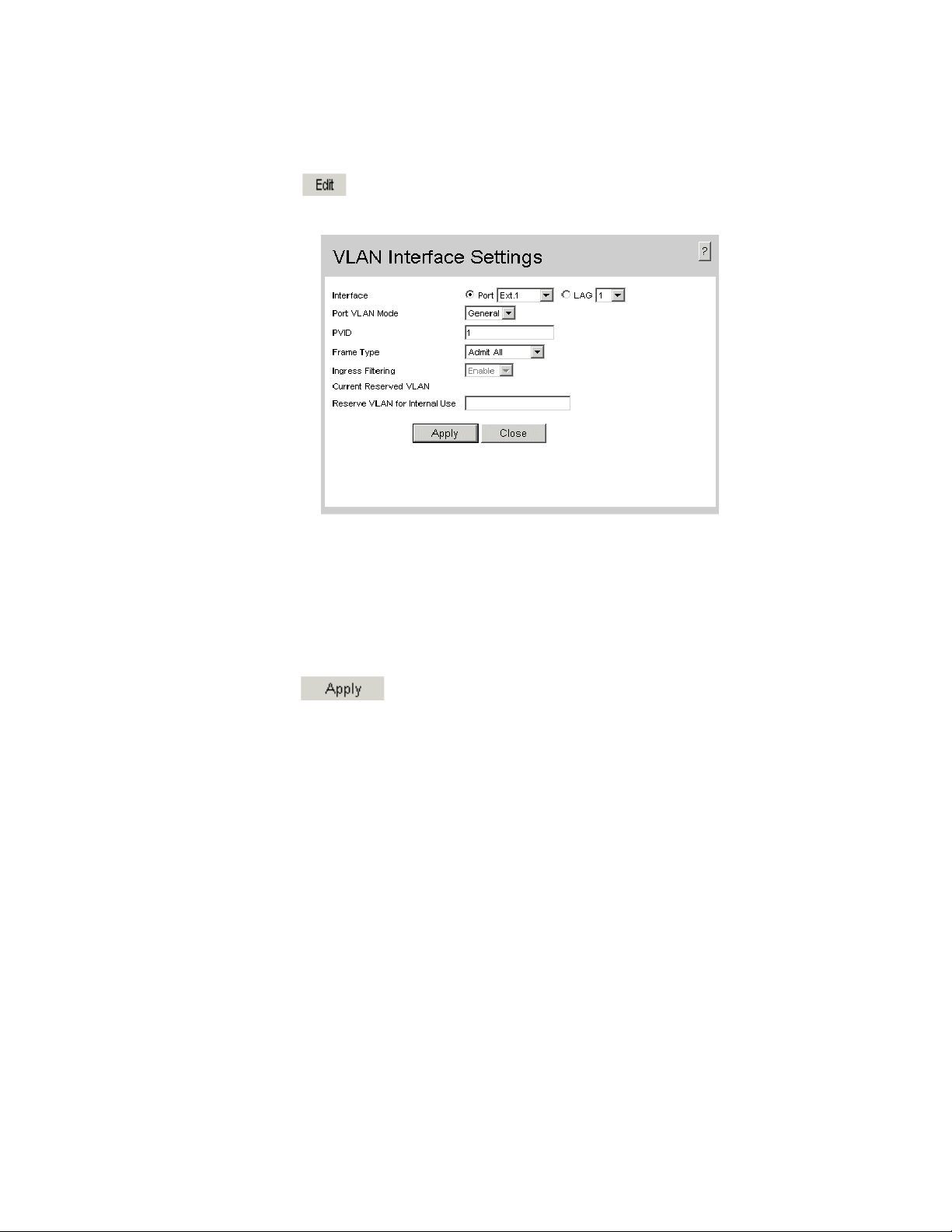
To modify the VLAN interface settings:
1. Click . The Interface Settings Page opens:
Figure 39. VLAN Interface Settings Page
In addition the fields appearing on the Interface Settings Page, the VLAN Interface
Settings Page contains the following fields:
• Current Reserved VLAN — Displays the current reserved VLAN on the interface.
• Reserve VLAN for Internal Use — Indicates the VLAN selected by the user to be
the reserved VLAN if not in use by the system.
2. Modify the relevant fields.
3. Click . The VLAN membership is modified
Intel® Gigabit Ethernet Switch AXXSW1GB User Guide 55
Page 69

Defining VLAN Groups
VLAN groups increase network flexibility and portability. For example, network users
grouped by MAC address can log on to the network from multiple locations without
moving between VLANs.
VLANs can be grouped by MAC address, Subnets, and Protocols. Once a user logs on, the
system attempts to classify the user by MAC address. If the user cannot be classified by
MAC address, the system attempts to classify the user by Subnet. If the subnet
classification is unsuccessful, the system attempts to classify the user by protocol. If the
protocol classification is unsuccessful, the user is classified by PVID.
VLAN groups allow network managers to define VLAN groups based on specific criteria,
including MAC addresses, network subnets, and protocols. This section contains the
following topics:
• Defining VLAN MAC Based Groups
• Defining VLAN Subnet Based Groups
• Defining VLAN Protocol Based Groups
• Mapping Groups to VLANs
56 Intel® Gigabit Ethernet Switch AXXSW1GB User Guide
Page 70

Defining VLAN MAC Based Groups
The VLAN MAC-based Groups Page allows network managers to group VLANs based on
the VLAN MAC address.
To define VLAN MAC Based Groups:
1. Click Layer 2 > VLAN > VLAN Groups > MAC-based Groups. The VLAN
MAC-based Groups Page opens:
Figure 40. VLAN MAC-based Groups Page
The VLAN MAC-based Groups Page contains the following fields:
• MAC Address — Displays the MAC address associated with the VLAN group.
• Prefix — Displays the MAC prefix associated with the VLAN group.
• Group ID — Displays the VLAN Group ID.
2. Click . The Add VLAN MAC-based Groups Page opens:
Intel® Gigabit Ethernet Switch AXXSW1GB User Guide 57
Page 71

Figure 41. Add VLAN MAC-based Groups Page
In addition to the fields in the VLAN MAC-based Groups Page, the Add VLAN MACbased Groups Page contains the following additional fields:
• MAC Group ID — Defines the Group ID associated with the VLAN group.
• Prefix — Defines the MAC prefix associated with the VLAN group.
• Host — Defines the specified MAC address as the only address associated with the
VLAN group.
3. Define the fields.
4. Click . The MAC based VLAN group is defined, and the device is
updated.
To modify a MAC Based VLAN Group:
1. Click Layer 2 > VLAN > VLANS Groups > MAC-based Groups. The VLAN
MAC-based Groups Page opens.
2. Click . The MAC Groups Settings Page opens:
Figure 42. MAC Groups Settings Page
3. Modify the fields.
4. Click . The MAC based VLAN group is modified, and the device is
updated.
58 Intel® Gigabit Ethernet Switch AXXSW1GB User Guide
Page 72

Defining VLAN Subnet Based Groups
The Subnet-based Group Settings allows network managers to group VLANs based on
their subnet. To define VLAN Subnet-based Groups:
1. Click Layer 2 > VLAN > VLAN Groups > Subnet-based Groups. The VLAN
Subnet-based Groups Page opens:
Figure 43. VLAN Subnet-based Groups Page
The VLAN Subnet-based Groups Page contains the following fields:
• IP Address — Displays the IP address associated with the VLAN subnet group.
• Prefix — Displays the network prefix associated with the VLAN group.
• Group ID — Displays the VLAN group ID associated with the VLAN subnet
group.
2. Click . The Add VLAN Subnet-based Groups Page opens:
Intel® Gigabit Ethernet Switch AXXSW1GB User Guide 59
Page 73

Figure 44. Add VLAN Subnet-based Groups Page
3. Define the fields.
4. Click . The Subnet based VLAN group is defined, and the device is
updated.
To modify a Subnet VLAN Group:
1. Click Layer 2 > > VLAN > VLAN Groups > Subnet-based Groups. The VLAN
Subnet-based Groups Page opens.
2. Click . The Subnet-based Group Settings opens.
Figure 45. Subnet-based Group Settings
60 Intel® Gigabit Ethernet Switch AXXSW1GB User Guide
Page 74

Defining VLAN Protocol Based Groups
The VLAN Protocol Groups Page contains information regarding protocol names and the
VLAN Ethernet type. Interfaces can be classified as a specific protocol based interface.
The classification places the interface into a protocol group. To define protocol based
VLANs
1. Click Layer 2 > > VLAN > VLAN Groups > Protocol-based Groups. The VLAN
Protocol Groups Page opens:
Figure 46. VLAN Protocol Groups Page
The VLAN Protocol Groups Page contains the following fields:
• Frame Type — Displays the packet type. Possible field values are Ethernet,
RFC1042, and LLC Other.
• Protocol Value — Displays the user-defined protocol name.
• Group ID — Displays the ID number assigned to frames containing specified
protocol value. The possible field range is 1 - 2147483647.
2. Click . The Add Protocol-based Groups Page opens:
Intel® Gigabit Ethernet Switch AXXSW1GB User Guide 61
Page 75

Figure 47. Add Protocol-based Groups Page
In addition to the fields in the VLAN Protocol Groups Page, the Add Protocol-based
Groups Page contains the following additional fields:
• Frame Type — Displays the packet type. Possible field values are Ethernet,
RFC1042, and LLC Other.
• Protocol Value — Displays the protocol group type. The possible field values are:
— IP — IP Internet Protocol (IP).
— IPX — Internet Packet Exchange (IPX).
— ARP — The Address Resolution Protocol (ARP) converts IP addresses into
physical addresses and maps the IP address to a MAC address. ARP allows a
host to communicate with other hosts only when the IP address of its neighbors
is known.
• Ethernet-Based Protocol Value — Displays the Ethernet protocol value.
3. Define the fields.
4. Click . The protocol based VLAN group is defined, and the device is
updated.
62 Intel® Gigabit Ethernet Switch AXXSW1GB User Guide
Page 76

To Modify a Protocol Based VLAN Group:
1. Click Layer 2 > VLAN > VLAN Groups > Protocol Based Groups. The VLAN
Protocol Groups Page opens.
2. Click . The Protocol-based Groups Settings Page opens:
Figure 48. Protocol-based Groups Settings Page
3. Modify the fields.
4. Click . The protocol based VLAN group is defined, and the device is
updated. au
Intel® Gigabit Ethernet Switch AXXSW1GB User Guide 63
Page 77

Mapping Groups to VLANs
The Mapping Groups to VLAN Page allows network managers to assign specific
interfaces to specific VLAN groups. To map interfaces to VLAN groups:
1. Click Layer 2 > VLANS > VLAN Groups > Mapping Groups to VLAN. The
Mapping Groups to VLAN Page opens:
Figure 49. Mapping Groups to VLAN Page
The Mapping Groups to VLAN Page contains the following fields:
• Group Type — Displays the VLAN Group type to which the interface is attached.
The possible field values are:
— MAC-based — Indicates the interface is attached to a MAC based VLAN group.
— Subnet-based — Indicates the interface is attached to a Subnet based VLAN
group.
— Protocol-based — Indicates the interface is attached to a Protocol based VLAN
group.
• Interface — Displays the interface attached to the VLAN group.
• Group ID — Displays the VLAN Group ID.
• VLAN ID — Displays the VLAN ID.
64 Intel® Gigabit Ethernet Switch AXXSW1GB User Guide
Page 78

2. Click . The Mapping Groups to VLAN Settings Page Mapping
Groups to VLAN Settings Page opens:
Figure 50. Mapping Groups to VLAN Settings Page
3. Modify the fields.
4. Click . The interfaces mappings are modified, and the device is
updated.
Intel® Gigabit Ethernet Switch AXXSW1GB User Guide 65
Page 79

Configuring GARP
This section contains information for configuring Generic Attribute Registration Protocol
(GARP). This section includes the following topics:
• Defining GARP
• Defining GVRP
Defining GARP
The Generic Attribute Registration Protocol (GARP) is a general-purpose protocol that
registers any network connectivity or membership-style information. GARP defines a set
of devices interested in a given network attribute, such as VLAN or multicast address.
When configuring GARP, ensure the following:
• The leave time must be greater than or equal to three times the join time.
• The leave-all time must be greater than the leave time.
• Set the same GARP timer values on all Layer 2-connected devices. If the GARP
timers are set differently on the Layer 2-connected devices, the GARP application
does not operate successfully.
To define the GARP settings on the device:
1. Click Layer 2 > VLAN > GARP Settings. The GARP Settings Page opens:
Figure 51. GARP Settings Page
66 Intel® Gigabit Ethernet Switch AXXSW1GB User Guide
Page 80

The GARP Settings Page contains the following fields:
• Ports — Displays the Port GARP settings.
• LAGs — Displays the LAG GARP settings.
• Interface — Displays the port or LAG on which GARP is enabled.
• Join Timer — Indicates the amount of time, in milliseconds, that PDUs are
transmitted. The default value is 200 milliseconds.
• Leave Timer — Indicates the amount of time lapse, in milliseconds, that the device
waits before leaving its GARP state. Leave time is activated by a Leave All Time
message sent/received, and cancelled by the Join message received. Leave time must
be greater than or equal to three times the join time. The default value is 600
milliseconds.
• Leave All Timer — Indicates the amount of time lapse, in milliseconds, that all
devices waits before leaving the GARP state. The leave all time must be greater than
the leave time. The default value is 10,000 milliseconds.
2. Click . The GARP Parameters Settings Page opens:
Figure 52. GARP Parameters Settings Page
3. Define the relevant fields.
4. Click . The GARP parameters are defined, and the device is updated.
Intel® Gigabit Ethernet Switch AXXSW1GB User Guide 67
Page 81

Defining GVRP
GARP VLAN Registration Protocol (GVRP) is specifically provided for automatic
distribution of VLAN membership information among VLAN-aware bridges. GVRP
allows VLAN-aware bridges to automatically learn VLANs to bridge ports mapping,
without having to individually configure each bridge and register VLAN membership.
To define the GVRP parameters on the device:
1. Click Layer 2 > VLAN > GVRP Parameters. The GVRP Parameters Page
opens:
Figure 53. GVRP Parameters Page
The GVRP Parameters Page is divided into Port and LAG parameters. The field
definitions are the same. The GVRP Parameters Page contains the following fields:
• GVRP Global Status — Indicates if GVRP is enabled on the device. The possible
field values are:
— Enable — Enables GVRP on the device.
— Disable — Disables GVRP on the device.
• Ports — Displays the Port GVRP settings.
• LAGs — Displays the LAG GVRP settings.
• Interface — Displays the port or LAG on which GVRP is enabled.
68 Intel® Gigabit Ethernet Switch AXXSW1GB User Guide
Page 82

• GVRP State — Indicates if GVRP is enabled on the interface. The possible field
values are:
— Enable — Enables GVRP on the selected interface.
— Disable — Disables GVRP on the selected interface.
• Dynamic VLAN Creation — Indicates if Dynamic VLAN creation is enabled on the
interface. The possible field values are:
— Enable — Enables Dynamic VLAN creation on the interface.
— Disable — Disables Dynamic VLAN creation on the interface.
• GVRP Registration — Indicates if VLAN registration through GVRP is enabled on
the interface. The possible field values are:
— Enable — Enables GVRP registration on the interface.
— Disable — Disables GVRP registration on the interface.
2. Define the relevant fields.
3. Click . The GVRP parameters are defined, and the device is updated.
To modify the GVRP parameters:
1. Click . The GVRP Parameters Settings Page opens:
Figure 54. GVRP Parameters Settings Page
2. Define the relevant fields.
3. Click . The GVRP Interface parameters are sent, and the device is
updated.
Intel® Gigabit Ethernet Switch AXXSW1GB User Guide 69
Page 83

70 Intel® Gigabit Ethernet Switch AXXSW1GB User Guide
Page 84

7 Defining Forwarding Database
Packets addressed to destinations stored in either the Static or Dynamic databases are immediately
forwarded to the port. The Dynamic MAC Address Table can be sorted by interface, VLAN, or MAC
Address, whereas MAC addresses are dynamically learned as packets from sources that arrive at the
device. Static addresses are configured manually.
An address becomes associated with a port by learning the port from the frame’s source address, but if a
frame that is addressed to a destination MAC address is not associated with a port, that frame is flooded
to all relevant VLAN ports. To prevent the bridging table from overflowing, a dynamic MAC address,
from which no traffic arrives for a set period, is erased.
This section contains information for defining both static and dynamic forwarding database entries, and
includes the following topics:
• Defining Static Forwarding Database Entries
• Defining Dynamic Forwarding Database Entries
Intel® Gigabit Ethernet Switch AXXSW1GB User Guide 71
Page 85

Defining Static Forwarding Database Entries
The Static Addresses Page contains parameters for defining the age interval on the device. To prevent
static MAC addresses from being deleted when the device is reset, ensure that the port attached to the
MAC address is locked.
To configure the static forwarding database:
1. Click Layer 2 > Address Table > Static Addresses. The Static Addresses Page opens.
Figure 55. Static Addresses Page
The Static Addresses Page contains the following fields:
• Delete — Deletes the entry. The possible field values are:
— Checked — Deletes the selected entry.
— Unchecked — Maintains the current static forwarding database.
• VLAN ID — Displays the VLAN ID number to which the entry refers.
• MAC Address — Displays the MAC address to which the entry refers.
• Interface — Displays the interface to which the entry refers:
— Port — The specific port number to which the forwarding database parameters refer.
— LAG — The specific LAG number to which the forwarding database parameters refer.
72 Intel® Gigabit Ethernet Switch AXXSW1GB User Guide
Page 86

• Status — Displays how the entry was created. The possible field values are:
— Permanent — The MAC address is permanent.
— Delete on Reset — The MAC address is deleted when the device is reset.
— Delete on Timeout — The MAC address is deleted when a timeout occurs.
— Secure — The MAC Address is defined for locked ports.
Note: To prevent static MAC addresses from being deleted when the device is reset, make sure
that the port attached to the MAC address is locked.
2. Click . The Add Static MAC Address Page opens:
Figure 56. Add Static MAC Address Page
In addition to the fields in the Static Addresses Page, the Add Static MAC Address Page contains the
following additional field:
• VLAN Name — Displays the user-defined VLAN name.
3. Define the relevant fields.
4. Click . The Static MAC Addresses are defined, and the device is updated.
Intel® Gigabit Ethernet Switch AXXSW1GB User Guide 73
Page 87

Defining Dynamic Forwarding Database Entries
The Dynamic Addresses Page contains parameters for querying information in the Dynamic MAC
Address Table, including the interface type, MAC addresses, VLAN and table storing. The Dynamic
MAC Address table contains information about the aging time before a dynamic MAC address is erased
and includes parameters for querying and viewing the Dynamic MAC Address table. The Dynamic MAC
Address table contains address parameters by which packets are directly forwarded to the ports. The
Dynamic Address Table can be sorted by interface, VLAN and MAC Address.
To configure the Dynamic MAC Address table:
1. Click Layer 2 > Address Table > Dynamic Addresses. The Dynamic Addresses Page opens.
Figure 57.
The Dynamic Addresses Page contains the following fields:
Dynamic Addresses Page
• Aging Interval (Sec) — Specifies the amount of time the MAC Address remains in the Dynamic
Address Table before it times out. The default value is 300 seconds.
• Clear Table — Clears the current Address Table entries.
• Query by: — Sorts the addresses table by:
— Interface — Displays the interface to for which the dynamic address is defined.
— MAC Address — Specifies the MAC address for which the table is queried.
— VLAN ID — Specifies the VLAN ID for which the table is queried.
• Address Table Sort Key — Specifies the means by which the Dynamic MAC Address Table is
sorted. The address table can be sorted by MAC address, VLAN or interface.
74 Intel® Gigabit Ethernet Switch AXXSW1GB User Guide
Page 88

2. Define the fields.
3. Click . The Dynamic Address Aging field is defined, and the device is updated.
To query the Dynamic MAC Address Table:
1. Click Layer 2 > Address Table > Dynamic Addresses. The Dynamic Addresses Page opens.
2. Select an Address Table Sort Key.
3. Click . The Dynamic MAC Address Table is queried, and the results are displayed.
Intel® Gigabit Ethernet Switch AXXSW1GB User Guide 75
Page 89

76 Intel® Gigabit Ethernet Switch AXXSW1GB User Guide
Page 90

8 Configuring Multicast Forwarding
This section contains information for configuring Multicast forwarding, and includes the
following sections:
• Defining IGMP Snooping
• Defining Multicast Groups
• Defining Multicast Forward All Settings
Intel® Gigabit Ethernet Switch AXXSW1GB User Guide 77
Page 91

Defining IGMP Snooping
When IGMP Snooping is enabled globally, all IGMP packets are forwarded to the CPU.
The CPU analyzes the incoming packets and determines:
• Which ports want to join which Multicast groups.
• Which ports have Multicast routers generating IGMP queries.
Hosts on ports join a specific Multicast group by sending an IGMP report, learned by the
bridge. This results in the creation of the Multicast filtering database.
Note: Ensure that Bridge Multicast filtering is enabled before enabling IGMP Snooping (see
Defining Multicast Groups).
To enable IGMP Snooping:
1. Click Layer 2 > Multicast > IGMP Snooping. The IGMP Snooping Page opens:
Figure 58. IGMP Snooping Page
The IGMP Snooping Page contains the following fields:
• Enable IGMP Snooping Status — Indicates if IGMP Snooping is enabled on the
device. IGMP Snooping can be enabled only if Bridge Multicast Filtering is enabled.
The possible field values are:
— Checked — Enables IGMP Snooping on the device.
— Unchecked — Disables IGMP Snooping on the device.
• VLAN ID — Specifies the VLAN ID.
78 Intel® Gigabit Ethernet Switch AXXSW1GB User Guide
Page 92

• IGMP Snooping Status — Indicates if IGMP snooping is enabled on the VLAN. The
possible field values are:
— Enable — Enables IGMP Snooping on the VLAN.
— Disable — Disables IGMP Snooping on the VLAN.
• Auto Learn — Indicates if Auto Learn is enabled on the VLAN. If Auto Learn is
enabled, the device automatically learns about the existing multicast routers. The
possible field values are:
— Enable — Enables auto learn.
— Disable — Disables auto learn.
• Host Timeout — Indicates the amount of time the host waits to receive a message
before timing out. If an IGMP report for a multicast group wasn’t received on the port
from any host (located on the port), the port is deleted from the membership list of
that group. The default time is 260 seconds.
• MRouter Timeout — Indicates the amount of the time the Multicast router waits to
receive a message before it times out. If any MRouter message (IGMP query or any
other multicast router message), wasn’t received on the port, the port is deleted from
the MRouter membership port list. The default value is 300 seconds.
• Leave Timeout — Indicates the amount of time the host waits, after requesting to
leave the IGMP group and not receiving a Join message from another station, before
timing out. If a Leave Timeout occurs, the switch notifies the Multicast device to stop
sending traffic. The Leave Timeout value is either user-defined, or an immediate leave
value. The default timeout is 10 seconds.
2. Check the Enable IGMP Snooping Status checkbox.
3. Click . The IGMP Snooping Settings Page opens:
Figure 59. IGMP Snooping Settings Page
4. Modify the relevant fields.
5. Click . The IGMP global parameters are sent, and the device is
updated.
Intel® Gigabit Ethernet Switch AXXSW1GB User Guide 79
Page 93

Defining Multicast Groups
The Multicast Group Page displays the ports and LAGs attached to the Multicast service
group in the Ports and LAGs tables. The Port and LAG tables also reflect the manner in
which the port or LAGs joined the Multicast group. Ports and LAGs can be added either
to existing groups or to new Multicast service groups. The Multicast Group Page permits
new Multicast service groups to be created. The Multicast Group Page also assigns ports
to a specific Multicast service address group.
Bridge multicast groups are defined according to MAC addresses. In cases where the
Bridge Multicast Address is an IP Address it is required to be mapped to a MAC address.
Multiple IP address can be mapped to a single MAC address and are presented in the form
of an IP Address range (see Edit Multicast Group Page). The MAC address for the
multicast group is created as a result of mapping the last 23 bits of the IP Address to the
Last 23 bits of the MAC address and this allows multiple IP addresses to be mapped to
one MAC address. The first three octets of such a mapped MAC address have the standard
form of 01:00:5E:XX:XX:XX.
To define multicast groups:
1. Click Layer 2 > Multicast > Multicast Group. The Multicast Group Page opens:
Figure 60. Multicast Group Page
80 Intel® Gigabit Ethernet Switch AXXSW1GB User Guide
Page 94
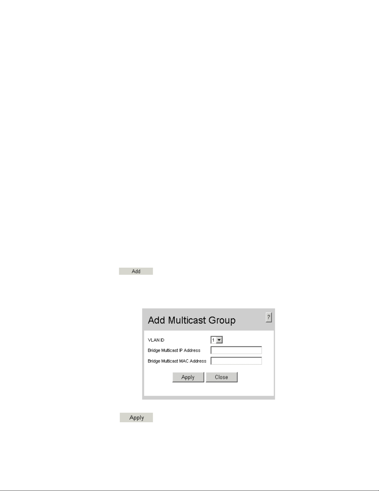
The Multicast Group Page contains the following fields:
• Enable Bridge Multicast Filtering — Indicate if bridge Multicast filtering is enabled
on the device. The possible field values are:
— Checked — Enables multicast filtering on the device.
— Unchecked — Disables multicast filtering on the device. If multicast filtering is
disabled, multicast frames are flooded to all ports in the relevant VLAN.
Disabled is the default value.
• VLAN ID — Identifies a VLAN and contains information about the multicast group
address.
• Bridge Multicast Address — Identifies the multicast group MAC address/IP
address.
• Ports — Displays port that can be added to a multicast service.
• LAGs — Displays LAGs that can be added to a multicast service.
• Interface — Displays the interface used to manage the device.
• Interface Status — Indicates the port/LAG status in relation to the Multicast group.
— Static — Attaches the port/LAG to the Multicast group as static member.
— Dynamic — Dynamically joins the port/LAG to the multicast group in the
Current Row.
— Forbidden — Indicates the port/LAG is not included in the Multicast group,
even if IGMP snooping designated the port to join a Multicast group.
— Exclude — Indicates the port/LAG is not part of a Multicast group.
2. Click . The Add Multicast Group Page opens:
Figure 61. Add Multicast Group Page
3. Define the relevant fields.
4. Click . The Multicast group is defined, and the device is updated.
Intel® Gigabit Ethernet Switch AXXSW1GB User Guide 81
Page 95

To modify the multicast group:
1. Click . The Edit Multicast Group Page opens:
Figure 62. Edit Multicast Group Page
2. Modify the relevant fields.
3. Click . The Multicast group is defined, and the device is updated.
82 Intel® Gigabit Ethernet Switch AXXSW1GB User Guide
Page 96

Defining Multicast Forward All Settings
The Multicast Forward-ALL Page allows users to define the ports which are filtered by
the IGMP snooping protocol. The IGMP Snooping protocol filters ports during the
forwarding process to a neighboring Multicast router or switch. Ports can either be defined
as:
• Forbidden — Excluded from IGMP Learned Port List.
• Forwarded — Added to the IGMP Learned Port List. The IGMP snooping interprets
Forward (static) ports as statically configured Multicast ports that propagates IGMP
reports and data. The Forward also adds the Multicast Group Forward (static) ports to
the Forward-All Forward (static) ports list.
To define multicast forward all settings:
1. Click Layer 2 > Multicast > Multicast Forward All. The Multicast Forward All
Page opens:
Figure 63. Multicast Forward All Page
The Multicast Forward All Page contains the following fields:
• VLAN ID — Displays the VLAN for which multicast parameters are displayed.
• Ports — Displays port that can be added to a multicast service.
• LAGs — Displays LAGs that can be added to a multicast service.
Intel® Gigabit Ethernet Switch AXXSW1GB User Guide 83
Page 97

• Interface — Displays the interface used to manage the device.
• Interface Status — Indicates the port/LAG status. The possible field values are:
— Static — Attaches the port/LAG to the Multicast group as static member.
— Dynamic — Dynamically joins ports/LAG to the multicast group in the Current
Row.
— Forbidden — Indicates the port/LAG is not included in the Multicast group,
even if IGMP snooping designated the port to join a Multicast group.
2. Exclude — Indicates the port/LAG is not part of a Multicast group.Select a VLAN
in the VLAN ID drop-down box.
3. Define the VLAN port settings.
4. Click . The Multicast Forward All settings are defined, and the device
is updated.
To modify the Multicast Forward All settings:
1. Click . The Multicast Forward All Page opens:
Figure 64. Edit Multicast Forward All Page
2. Define the relevant fields.
3. Click . The Multicast Forward All settings are defined, and the device
is updated.
84 Intel® Gigabit Ethernet Switch AXXSW1GB User Guide
Page 98

9 Configuring Spanning Tree
Spanning Tree Protocol (STP) provides tree topography for any arrangement of bridges.
STP also provides a single path between end stations on a network, eliminating loops.
Loops occur when alternate routes exist between hosts. Loops in an extended network can
cause bridges to forward traffic indefinitely, resulting in increased traffic and reducing
network efficiency.
The device supports the following STP versions:
• Classic STP — Provides a single path between end stations, avoiding and eliminating
Defining Spanning Tree
loops.
• Rapid STP — Detects and uses network topologies that provide faster convergence
of the spanning tree, without creating forwarding loops. For more information on
configuring Rapid STP, see
• Multiple STP — Provides various load balancing scenarios. For example, if port A is
blocked in one STP instance, the same port can be placed in the Forwarding State in
another STP instance. For more information on configuring Multiple STP, see
Defining Multiple STP.
Defining Rapid STP.
Intel® Gigabit Ethernet Switch AXXSW1GB User Guide 85
Page 99

Defining Spanning Tree
The Spanning Tree Properties Page contains parameters for enabling STP on the device.
To enable STP on the device:
1. Click Layer 2 > Spanning Tree > Properties. The Spanning Tree Properties Page
opens:
Figure 65. Spanning Tree Properties Page
The Spanning Tree Properties Page contains the following fields:
Global Settings
• Spanning Tree State — Indicates whether STP is enabled on the device. The possible
field values are:
— Enable — Enables STP on the device.
— Disable — Disables STP on the device.
• STP Operation Mode — Specifies the STP mode that is enabled on the device. The
possible field values are:
— Classic STP — Enables Classic STP on the device.
— Rapid STP — Enables Rapid STP on the device. This is the default value.
— Multiple STP — Enables Multiple STP on the device.
86 Intel® Gigabit Ethernet Switch AXXSW1GB User Guide
Page 100

• BPDU Handling — Determines how BPDU packets are managed when STP is
disabled on the port or device. BPDUs are used to transmit spanning tree information.
The possible field values are:
— Filtering — Filters BPDU packets when spanning tree is disabled on an
interface. This is the default value.
— Flooding — Floods BPDU packets when spanning tree is disabled on an
interface.
• Path Cost Default Values — Specifies the method used to assign default path cost to
STP ports. The possible field values are:
— Short — Specifies 1 through 65,535 range for port path cost. This is the default
value.
— Long — Specifies 1 through 200,000,000 range for port path cost. The default
path cost assigned to an interface varies according to the selected method (Hello
Time, Max Age, or Forward Delay).
Bridge Settings
• Priority — Specifies the bridge priority value. When switches or bridges are running
STP, each is assigned a priority. After exchanging BPDUs, the device with the lowest
priority value becomes the Root Bridge. The possible field range is 0 - 61440 seconds.
The default value is 32768. The bridge priority value is provided in increments of
4096.
• Hello Time — Specifies the device Hello Time. The Hello Time indicates the amount
of time in seconds a Root Bridge waits between configuration messages. The possible
field range is 1-10 seconds. The default is 2 seconds.
• Max Age — Specifies the device Maximum Age Time. The Maximum Age Time is
the amount of time in seconds a bridge waits before sending configuration messages.
The possible field range is 6 - 40 seconds. The default Maximum Age Time is
seconds.
20
• Forward Delay — Specifies the device Forward Delay Time. The Forward Delay
Time is the amount of time in seconds a bridge remains in a listening and learning
state before forwarding packets. The possible field range is 4 -30. The default is 15
seconds.
Designated Root
• Bridge ID — Identifies the Bridge priority and MAC address.
• Root Bridge ID — Identifies the Root Bridge priority and MAC address.
• Root Port — Indicates the port number that offers the lowest cost path from this
bridge to the Root Bridge. This field is significant when the bridge is not the Root
Bridge. The default is zero.
• Root Path Cost — Specifies the cost of the path from this bridge to the Root Bridge.
• Topology Changes Counts — Specifies the total amount of STP state changes that
have occurred.
• Last Topology Change — Indicates the amount of time that has elapsed since the
bridge was initialized or reset, and the last topographic change that occurred. The time
is displayed in a day-hour-minute-second format, such as 2 days 5 hours 10 minutes
and 4 seconds.
Intel® Gigabit Ethernet Switch AXXSW1GB User Guide 87
 Loading...