

Page 1

Intel® Astor II Server Chassis Subassembly Product Guide
A Guide for Technically Quali f i ed Assemblers of Intel® Identified Subassemblies/Products
Order Number: 722623-001
Page 2
If an FCC declaration of conformity marking is present on the board, the following statement applies:
FCC Declaration of Conformity
This device complies with Part 15 of the FCC Rules. Operation is subject to the following two conditions: (1)
this device may not cause harmful interference, and (2) this device must accept any interference received,
including interference that may cause undesired operation.
For questions related to the EMC performance of this product, contact:
Intel Corporation
5200 N.E. Elam Young Parkway
Hillsboro, OR 97124
1-800-628-8686
This equipment has been tested and found to comply with the limits for a Class B digital device, pursuant to
Part 15 of the FCC Rules. These limits are designed to provide reasonable protection against harmful
interference in a residential installation. This equipment generates, uses, and can radiate radio frequency
energy and, if not installed and used in accordance with the instructions, may cause harmful interference to
radio communications. However, there is no guarantee that interference will not occur in a particular
installation. If this equipment does cause harmful interference to radio or television reception, which can be
determined by turning the equipment off and on, the user is encouraged to try to correct the interference by
one or more of the following measures:
Reorient or relocate the receiving antenna.
Increase the separation between the equipment and the receiver.
Connect the equipment to an outlet on a circuit other than the one to which the receiver is connected.
Consult the dealer or an experienced radio/TV technician for help.
Canadian Department of Communications Compliance Statement:
This digital apparatus does not exceed the Class B limits for radio noise emissions from digital apparatus set
out in the Radio Interference Regulations of the Canadian Department of Communications.
Le présent appareil numerique német pas de bruits radioélectriques dépassant les limites applicables aux
appareils numériques de la classe B prescrites dans le Réglement sur le broullage radioélectrique édicté par
le ministére des Communications du Canada.
Disclaimer
Information in this document is provided in connection with Intel products. No license, express or implied, by
estoppel or otherwise, to any intellectual property rights is granted by this document. Except as provided in
Intel's Terms and Conditions of Sale for such products, Intel assumes no liability whatsoever, and Intel
disclaims any express or implied warranty, relating to sale and/or use of Intel products including liability or
warranties relating to fitness for a particular purpose, merchantability, or infringement of any patent, copyright
or other intellectual property right. Intel products are not designed, intended or authorized for use in any
medical, life saving, or life sustaining applications or for any other application in which the failure of the Intel
product could create a situation where personal injury or death may occur. Intel may make changes to
specifications and product descriptions at any time, without notice.
The Astor II Chassis may contain design defects or errors known as errata which may cause the product to
deviate from published specifications. Current characterized errata are available on request. Copies of
documents which have an ordering number and are referenced in this document, or other Intel literature, may
be obtained from:
Intel Corporation
P.O. Box 5937
Denver, CO 80217-9808
or call in North America 1-800-548-4725, Europe 44-0-1793-431-155, France 44-0-1793-421-777,
Germany 44-0-1793-421-333, other Countries 708-296-9333.
†
Third party brands and names are property of their respective owners.
Copyright Intel Corporation 1998.
Page 3

Contents
1 System Description
Kit Contents.......................................................................................................................... 7
Feature Summary ................................................................................................................ 7
Chassis Front Controls and Indicators......................................................................... 8
Chassis Back I/O Ports and Features.......................................................................... 9
Chassis Side View......................................................................................................10
Peripherals..........................................................................................................................11
External Bay for 5.25-inch Removable Media Devices ...............................................11
Internal Bay for 3.5-inch IDE Hard Drives...................................................................11
Hot-swap Bay.............................................................................................................11
Power Supply......................................................................................................................12
Checking the Power Cord...........................................................................................12
System Cooling...................................................................................................................12
System Security..................................................................................................................13
Mechanical Locks.......................................................................................................13
Monitoring...................................................................................................................13
2 Working Inside the System
Tools and Supplies Needed ................................................................................................15
Safety: Before You Remove the Side Cover.......................................................................15
Warnings and Cautions.......................................................................................................15
Removing the Side Cover....................................................................................................16
Installing Chassis Feet........................................................................................................17
Removing the Hot-swap Bay...............................................................................................18
Removing the IDE Drive Bay...............................................................................................19
Installing Server Board Clips and Bumpers.........................................................................21
I/O Shield............................................................................................................................22
Installing the Server Board..................................................................................................22
Installing a Chassis Intrusion Switch ...................................................................................24
Removing the Front Cover..................................................................................................25
Installing the Diskette Drive.................................................................................................26
Removing the Diskette Drive...............................................................................................26
Hard Drives.........................................................................................................................27
Drive Cabling Considerations .....................................................................................27
Installing a Hard Drive into the IDE Drive Bay.............................................................27
Removing a Hard Drive from the IDE Drive Bay.........................................................28
Installing the IDE drive bay.........................................................................................29
Installing a 5.25-inch Peripheral Device......................................................................30
Removing a 5.25-inch Peripheral Device....................................................................32
Installing the Front Cover....................................................................................................33
Installing the Hot-swap Bay.................................................................................................33
Installing an Add-in Board ...................................................................................................33
Removing an Add-in Board.................................................................................................34
iii
Page 4

Installing the Side Cover......................................................................................................35
Hot-swap Bay......................................................................................................................36
SCSI Hard Disk Drives ...............................................................................................36
Mounting a SCSI SCA2 Hard Disk Drive in a Plastic Carrier.......................................36
Installing a SCSI SCA2 Hard Disk Drive in the Hot-swap Bay ....................................37
Hot-swapping a SCSI SCA2 Hard Disk Drive .............................................................38
Fans ...................................................................................................................................39
Removing the Front Fan.............................................................................................39
Installing the Front Fan...............................................................................................40
Removing a Hot-swap Bay Fan..................................................................................41
Installing a Hot-swap Bay Fan....................................................................................41
Hot-swap Backplane ...........................................................................................................42
Removing the SCSI Backplane...................................................................................42
Installing the SCSI Backplane.....................................................................................43
Front Panel Board...............................................................................................................44
Removing the Front Panel Board................................................................................44
Installing the Front Panel Board..................................................................................44
3 Technical Reference
Power Supply Specifications...............................................................................................45
Input Voltages.............................................................................................................45
Output Voltages..........................................................................................................45
Environmental Specifications ..............................................................................................46
SCSI Hot-swap Backplane Connectors...............................................................................47
Ultra2/LVD SCSI 16-Bit Connector.............................................................................47
Ultra2/LVD SCA2 SCSI 16-Bit Connectors.................................................................48
Power Connectors......................................................................................................49
Backplane Fan Connector..........................................................................................49
Front Panel Cable Connector.....................................................................................50
4 Regulatory Information
Regulatory Compliance.......................................................................................................51
Safety Compliance......................................................................................................51
EMC Compliance........................................................................................................52
Regulatory Compliance Markings...............................................................................53
Electromagnetic Compatibility Notice (USA)........................................................................53
FCC Declaration of Conformity...................................................................................54
Electromagnetic Compatibility Notices (International)..........................................................54
Installation Safety Instructions....................................................................................55
Use Only for Intended Applications.............................................................................56
A Equipment Log and Worksheets
Equipment Log....................................................................................................................57
Current Usage.....................................................................................................................59
Calculating Power Usage............................................................................................59
iv Intel Astor II Server Chassis Subassembly Product Guide
Page 5

B Warnings
WARNING: English (US)....................................................................................................62
AVERTISSEMENT: Français..............................................................................................64
WARNUNG: Deutsch.........................................................................................................66
AVVERTENZA: Italiano......................................................................................................68
ADVERTENCIAS: Español.................................................................................................70
C Warranty
Limited Warranty for Intel® Server Chassis Subassembly Products....................................73
Extent of Limited Warranty..................................................................................................73
Warranty Limitations and Exclusions...................................................................................74
Limitations of Liability..................................................................................................74
How to Obtain Warranty Service.........................................................................................75
Telephone Support.....................................................................................................75
Returning a Defective Product....................................................................................76
Figures
1. Front Controls and Indicators ...................................................................................... 8
2. Back I/O Ports and Features....................................................................................... 9
3. Chassis Side View......................................................................................................10
4. System Security.........................................................................................................13
5. Removing the Side Cover...........................................................................................17
6. Removing the Hot-swap Bay......................................................................................18
7. Disconnect Cables and Remove Screws....................................................................19
8. IDE Hard Drive Bay....................................................................................................20
9. Rubber Bumper and Standoff Clip Placement ............................................................21
10. Installing the I/O Shield (typical shield shown)............................................................22
11. Installing the Server Board (typical board shown).......................................................23
12. Installing a Chassis Intrusion Switch...........................................................................24
13. Removing the Front Cover..........................................................................................25
14. Installing the Diskette Drive........................................................................................26
15. IDE Cable Dimensions................................................................................................27
16. IDE Hard Drive...........................................................................................................28
17. Disconnect Cables and Remove Screws....................................................................29
18. Remove Filler Panels and EMI Shields.......................................................................30
19. Snap-in Plastic Slide Rails..........................................................................................31
20. Installing a Removable Media Device.........................................................................32
21. Installing an Add-in Board...........................................................................................34
22. Hard Disk Drive and Plastic Carrier............................................................................37
23. Installing a Hard Disk Drive ........................................................................................38
24. Removing the Fan Bracket.........................................................................................39
25. Installing the Front Fan...............................................................................................40
26. Removing the Hot-swap Bay Fan Bracket..................................................................41
27. Removing the Plastic Shroud .....................................................................................42
28. Removing the SCSI Backplane...................................................................................43
29. Removing the Front Panel Board................................................................................44
Contents v
Page 6

Tables
1. Feature Summary........................................................................................................ 7
2. Fan Cable Connector Pinout ......................................................................................39
3. Power Supply Output Voltages...................................................................................45
4. Environmental Specifications......................................................................................46
5. Wide/Fast SCSI 16-Bit Connector Pinout ...................................................................47
6. Wide/Fast SCA2 SCSI 16-Bit Connector Pinout.........................................................48
7. Power Connector Pinout.............................................................................................49
8. Backplane Fan Connector Pinout...............................................................................49
9. Front Panel Connector Pinout ....................................................................................50
10. Power Usage Worksheet 1.........................................................................................59
11. Power Usage Worksheet 2.........................................................................................60
vi Intel Astor II Server Chassis Subassembly Product Guide
Page 7

1 System Description
Kit Contents
The Astor II chassis subassembly kit includes this Product Guide, a power cord, an I/O shield EMI
gasket, two chassis feet, and three hardware bags:
Server board installation bag: includes three rubber bumpers, 13 standoff clips, and 13
retention screws.
Chassis intrusion switch bag: includes one intrusion switch/cable assembly, one mounting
screw, and three wire tie clips.
Internal/external peripheral mounting bag: includes four 5.25-inch external drive rails and
mounting screws without washers (2 screws/rail x 4 + 2 for diskette = 10 total); mounting
screws with washers for SCA2 hard drive caddies (4 screws/drive x 5 + 1 spare = 21 total);
mounting screws with washers for chassis feet (2 screw/foot x 2 = 4 total); and gold colored
mounting screws for IDE drives (4 screws/drive x 2 = 8 total).
Feature Summary
Table 1. Feature Summary
Feature Description
Drive Bays One 3.5-inch diskette drive bay, accessible from front.
Two 5.25-inch wide bays that are externally accessible, designed to hold halfheight standard removable media devices; the bays can be converted into a
single full-height bay.
Hot-swap bay for 3.5-inch hard disk drives: space for up to five 1-inch high,
SCA2 hard drives.
Two 3.5-inch wide bays that are not externally accessible, designed to hold
half-height IDE drives.
Expansion slot covers Up to seven expansion slots can be used; every slot that does not have an
add-in board installed must have a slot cover installed.
Power supply 300 watt power factor correction (PFC) power supply, integrated cooling fan.
Detachable AC power cord.
Cooling Three system fans inside the chassis and one power supply fan provide
cooling and airflow.
7
Page 8
Chassis Front Controls and Indicators
C
D
E
F
A
B
K
G
H
I
J
OM07034
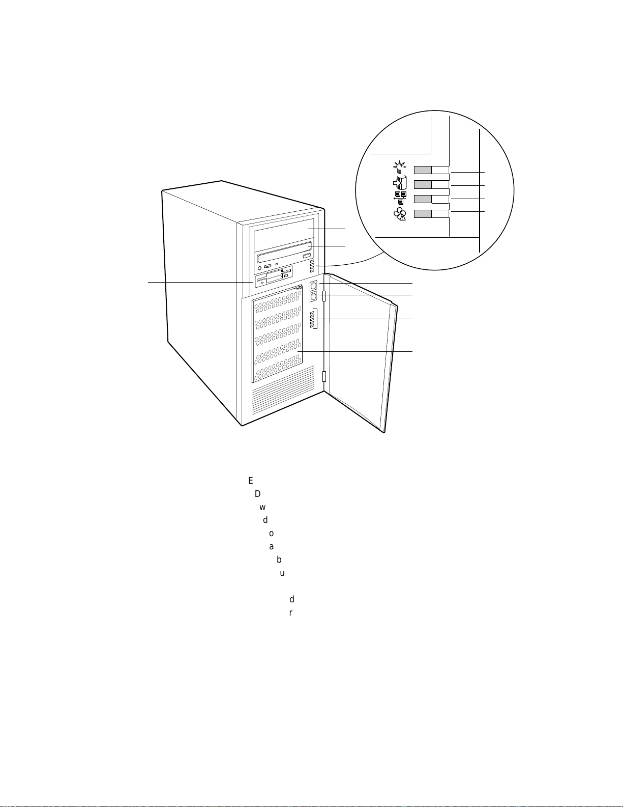
Figure 1. Front Controls and Indicators
A.Empty 5.25-inch drive bay
B.CD-ROM drive*
C.Power LED
D.Hard disk access LED
E.Network LED
F.Fan fault LED
G.Power button
H.Reset button
I.Hot-swap drive failure LEDs
J.Hot-swap drive bay
K.Diskette drive*
* Items shown may not be included in the chassis.
8 Intel Astor II Server Chassis Subassembly Product Guide
Page 9
Chassis Back I/O Ports and Features
A
F G
B
E
C
D
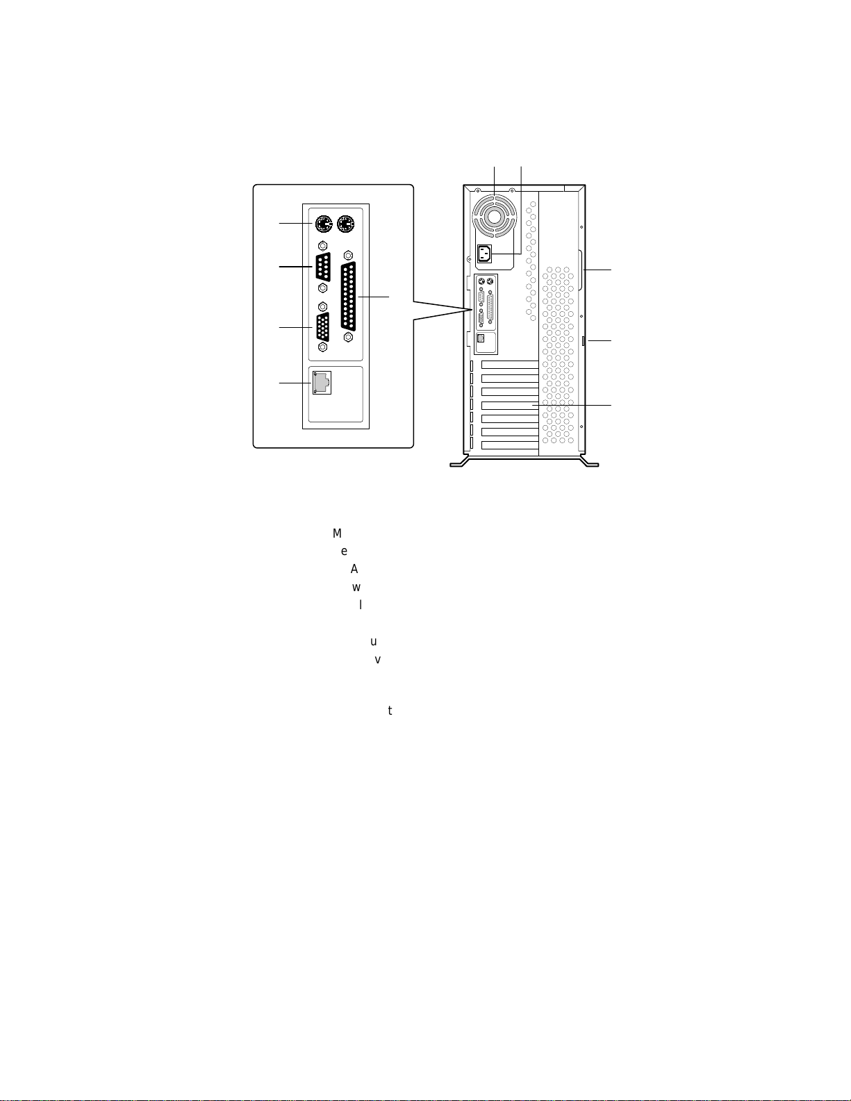
Figure 2. Back I/O Ports and Features
A.Mouse and keyboard connectors*
B.Serial port A, COM1*
C.VGA monitor connector*
D.Network connector port*
E.Parallel port*
F.Power supply fan
G.AC input power connector
H.Side cover grip handle
I.Loop for padlock (padlock not supplied, see page 13
for padlock size)
J.Seven slot covers
* Typical baseboard I/O connectors shown.
H
I
J
OM07038
System Description 9
Page 10
Chassis Side View
A
L
B
C
K
J
I
D
H
E
G F
OM07563
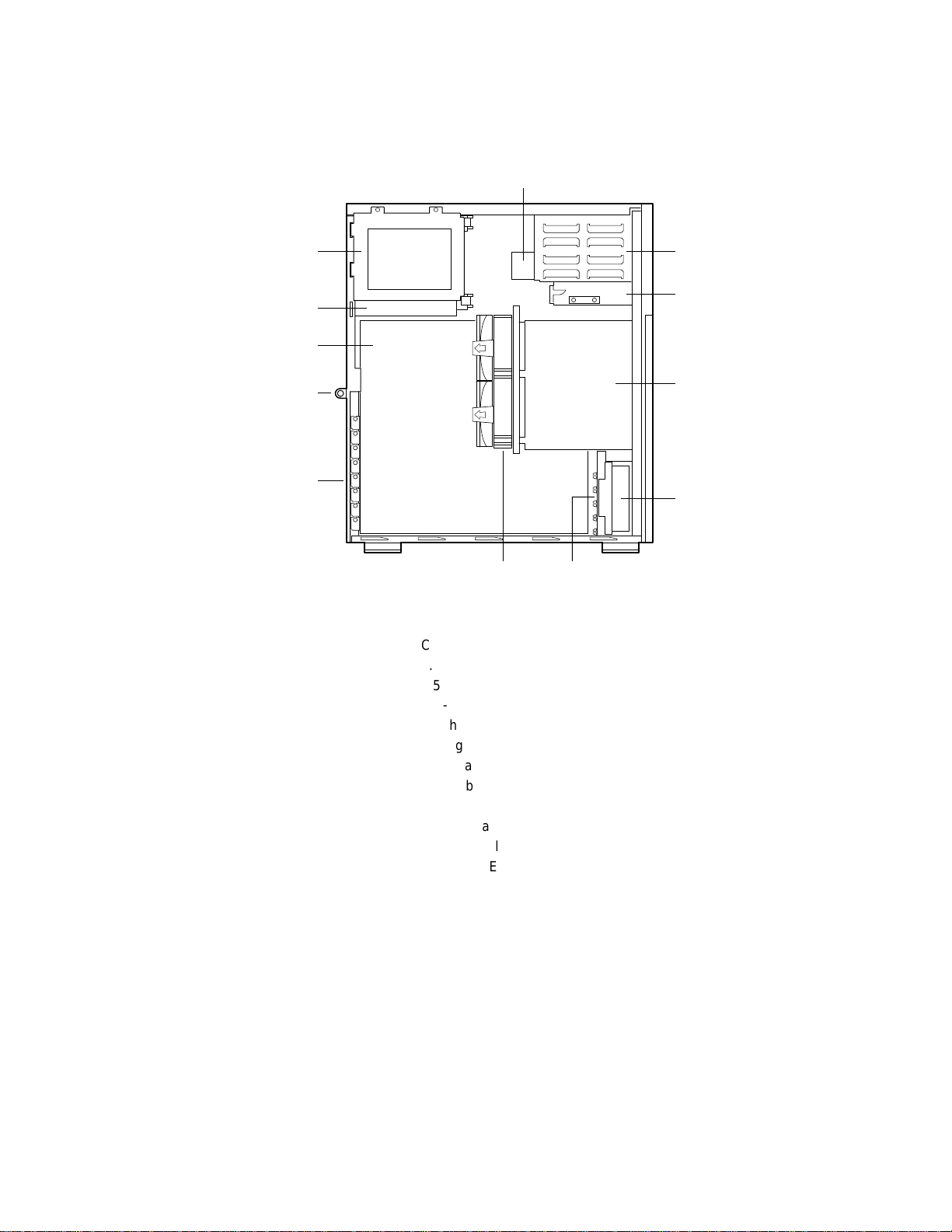
Figure 3. Chassis Side View
A.CD-ROM drive*
B.5.25-inch external bays
C.3.5-inch diskette drive*
D.Hot-swap drive bay
E.Fan housing
F.Card guide
G.Hot-swap fan shroud with two fans
H.Add-in board expansion slot covers
I.Security lock
J.Server board
K.Power supply
L.3.5-inch IDE drive bay
* Items shown may not be included in the chassis.
10 Intel Astor II Server Chassis Subassembly Product Guide
Page 11
Peripherals
External Bay for 5.25-inch Removable Media Devices
The chassis has a bay for two 5.25-inch half-height peripherals that is accessible from the front of
the system. This bay is intended to provide space for CD-ROM, tape backup or other removable
devices.
You can convert the 5.25-inch bays to a single full-height bay. We recommend that you do not use
this bay for hard disk drives, because they generate EMI, ESD susceptibility increases, and the
drive will not be adequately cooled.
Internal Bay for 3.5-inch IDE Hard Drives
The chassis has a 3.5-inch bay for two half-height or 1-inch high IDE hard drives. The bay is not
externally accessible.
Hot-swap Bay
A hot-swap bay is provided for five SCSI SCA2 hard drives that are 3.5 inches wide and 1 inch
high. The bay is designed for drives that consume up to 17 watts of power each. Drives must be
specified to run at a maximum ambient temperature of 50 C.
The system was designed to allow the user to install a Redundant Array of Independent Disks
(RAID). A software implementation with onboard SCSI or an add-in RAID controller card can be
used to set up RAID applications.
SCSI Hot-swap Backplane
The hot-swap backplane provides the following:
Five Single Connector Assembly (SCA2) connectors for SCA2-compatible SCSI drives
Power control for each drive, including automatic slot-power-down upon removing a drive
Signal for a fault indicator on the front panel for each drive
Internal IMB (Intelligent Management Bus)
Two +12 V connectors for a fan with tachometer
Local IMB-based temperature sensor
The SCSI hot-swap backplane provides control signals and power for five Ultra2/LVD 3.5-inch,
1-inch high, SCA2 SCSI hard disk drives. The backplane receives control signals from the SCSI
controller on the server board through a cable connected to the wide SCSI connector on the
backplane. The backplane is powered through cables connected to the two power connectors.
The drives get their control signals and power from the SCA2 connectors on the backplane.
The fault indicators on the front panel indicate failure status for each drive in the bay. These
indicators get their signals through a cable connected to the front panel connector on the
backplane.
System Description 11
Page 12
The temperature sensor on the backplane provides temperature information to the BMC (baseboard
management controller) on the server board through chassis service messages.
The backplane power control will power down a drive when a failure is detected and reported to
the SCSI bus. When a new drive is inserted, the power control waits a short time for the drive to
become fully seated and then applies power to the drive.
Power Supply
The 300 watt PFC (power factor correction) universal type power supply is designed to minimize
EMI. The supply operates within the following voltage ranges and is rated as follows:
100-120 V at 50/60 Hertz (Hz); 4.6 A maximum
200-240 V at 50/60 Hz; 2.3 A maximum
The DC output voltages of the power supply are +5 V, +12 V, +3.3 V, -5 V, -12 V, and
+5 V standby. Power to the server board is provided through the power cable to the 24-pin main
power connector.
Checking the Power Cord
WARNING
Do not attempt to modify or use a supplied AC power cord if it is not the
exact type required.
If a power cord supplied with the system is not compatible with the AC wall outlet in your region,
get one that meets the following criteria:
The cord must be rated for the available AC voltage and have a current rating that is at least
125% of the current rating of the system.
The connector that plugs into the wall outlet must be a grounding-type male plug designed
for use in your region. It must have certification marks showing certification by an agency
acceptable in your region.
The connector that plugs into the AC receptacle on the system power supply must be an IEC
320, sheet C13, type female connector.
In Europe, the cord must be less than 4.5 meters (14.76 feet) long, and it must be flexible
<HAR> (harmonized) or VDE certified cordage to comply with the system's safety
certifications.
System Cooling
The chassis includes four tachometer fans for cooling and airflow. One of these is the integrated
fan in the power supply.
NOTE
✏
The chassis side cover must be on the system for proper cooling.
12 Intel Astor II Server Chassis Subassembly Product Guide
Page 13
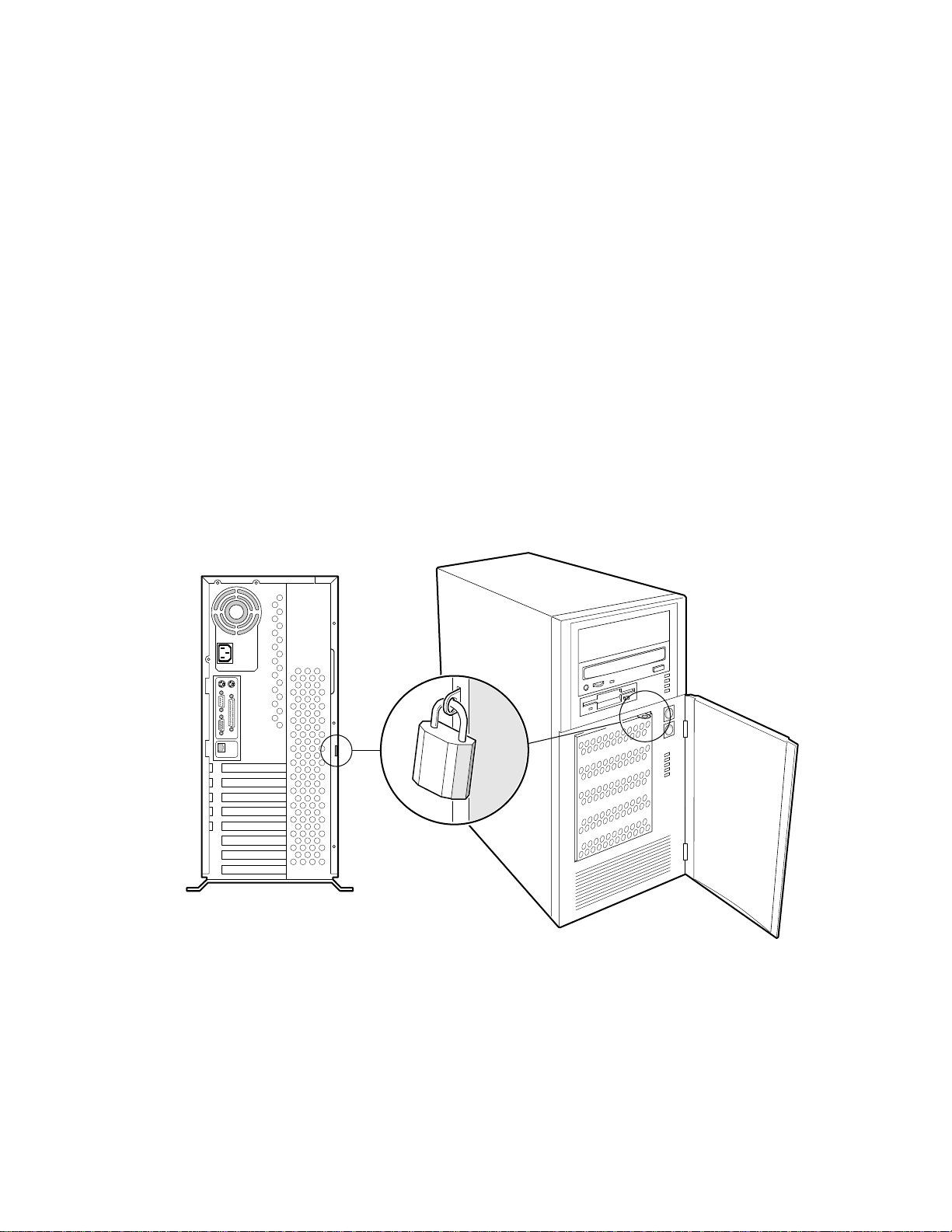
System Security
To help prevent unauthorized entry or use of the system, the chassis includes a chassis intrusion
switch that can be monitored by Server Management software and two padlock loops.
Mechanical Locks
A padlock loop on the rear of the system side cover can be used to prevent access to the
microprocessors, memory, and add-in cards. A variety of lock sizes can be accommodated by the
.300 diameter loop.
A padlock loop on the hard drive bay EMI door provides security for the hot swap hard drives.
†
The allotted space accommodates a MasterLock
.815” H x .830” W x .430” D. Pall diameter .145”
Monitoring
Install the chassis intrusion switch. When the side cover is removed, the switch transmits a signal
to the BMC on the server board. Server management software can be programmed to respond to
an intrusion by powering down or by locking the keyboard, for example.
model 120-D or equivalent lock. Dimensions:
OM07044
Figure 4. System Security
System Description 13
Page 14

14 Intel Astor II Server Chassis Subassembly Product Guide
Page 15
2 Working Inside the System
Tools and Supplies Needed
Phillips (cross head) screwdriver (#2 bit)
Antistatic wrist strap (recommended)
Needle-nosed pliers
Safety: Before You Remove the Side Cover
Before removing the system side cover for any reason, observe these safety guidelines.
1.Turn off all peripheral devices connected to the system.
2.Turn off the system by pressing the power button on the front of the system. Then unplug the
AC power cord from the system or wall outlet.
3.Label and disconnect all peripheral cables and all telecommunication lines connected to I/O
connectors or ports on the back of the system.
4.Provide some electrostatic discharge (ESD) protection by wearing an antistatic wrist strap
attached to chassis ground of the system—any unpainted metal surface—when handling
components.
Warnings and Cautions
These warnings and cautions apply whenever you remove the side cover of the system to access
components inside the system. Only a technically qualified person should integrate and configure
the system.
WARNINGS
The power button (a convex button) on the front panel DOES NOT turn
off the system AC power. To remove power from system, you must
unplug the AC power cord from the wall outlet or the system.
Hazardous electrical conditions may be present on power, telephone,
and communication cables. Turn off the system and disconnect the
power cords, telecommunications systems, networks, and modems
attached to the system before opening it. Otherwise, personal injury or
equipment damage can result.
Hazardous voltage, current, and energy levels are present inside the
power supply. There are no user-serviceable parts inside it; servicing
should be done by technically qualified personnel.
15
Page 16

CAUTIONS
ESD can damage disk drives, boards, and other parts. Perform all
procedures in this chapter only at an ESD workstation. If one is not
available, provide some ESD protection by wearing an antistatic wrist strap
attached to chassis groundany unpainted metal surfaceon your system
when handling parts.
Always handle boards carefully. They can be extremely sensitive to ESD.
Hold boards only by their edges. Do not touch the connector contacts. After
removing a board from its protective wrapper or from the system, place the
board component side up on a grounded, static free surface. If you place the
server board on a conductive surface, the battery leads may short out. If
they do, this will result in a loss of CMOS data and will drain the battery.
Use a conductive foam pad if available but not the board wrapper. Do not
slide board over any surface.
For proper cooling and airflow, always install the chassis side cover before
turning on the system. Operating it without the cover in place can damage
system parts.
Removing the Side Cover
You need to remove the chassis side cover, and in some cases the front cover, to gain access to
components inside the system.
1.Observe the safety and ESD precautions at the beginning of this chapter.
2.Turn off all peripheral devices connected to the system.
3.Turn off the system by pressing the power button on the front panel, AND unplugging the AC
power cord.
4.Label and disconnect all peripheral cables attached to the I/O panel on the back of the system.
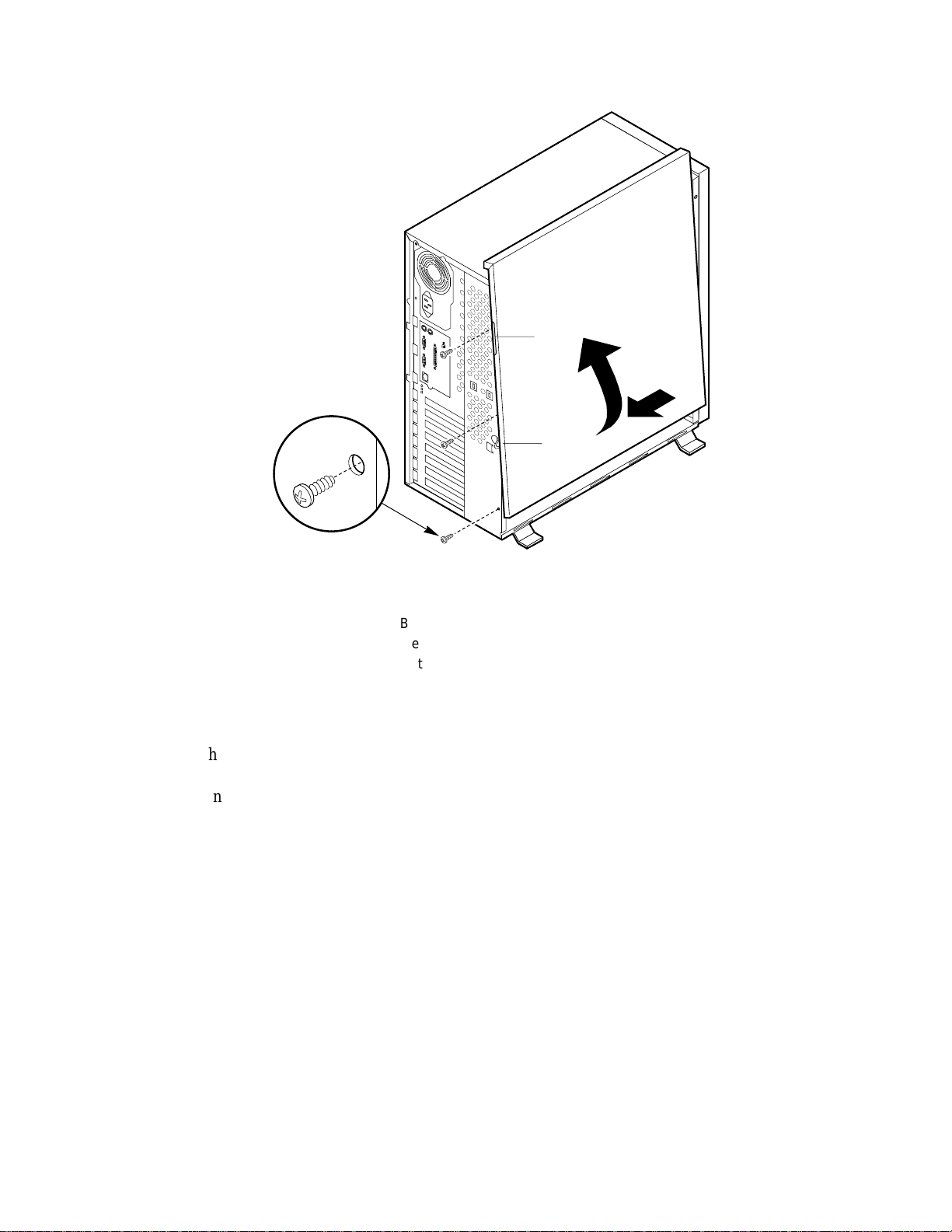
5.Remove and save the three screws from the side cover; you will need them later to reattach the
cover.
6.Place the fingertips of your left hand under the built in handle on the back of the cover.
7.Using an even pull, slide the cover backward, about an inch, until it stops.
8.Using your left hand, pull the back end of the cover toward you to disengage its bottom row of
tabs from the notches in the chassis.
9.Using both hands, lift the cover upward to disengage the top row of tabs from the notches in
the top edge of the chassis. Set the cover aside.
16 Intel Astor II Server Chassis Subassembly Product Guide
Page 17
A
B
C
OM06410
Figure 5. Removing the Side Cover
A.Built in handle
B.Metal loop (for padlock)
C.Retaining screws (3)
Installing Chassis Feet
1.Each chassis foot has two sets of holes. The larger holes fit over alignment features in the
chassis to assist positioning the feet.
2.Align the smaller holes with the corresponding screw holes on the chassis bottom, and attach
each foot with two screws (silver screws with washers are provided).
Working Inside the System 17
Page 18
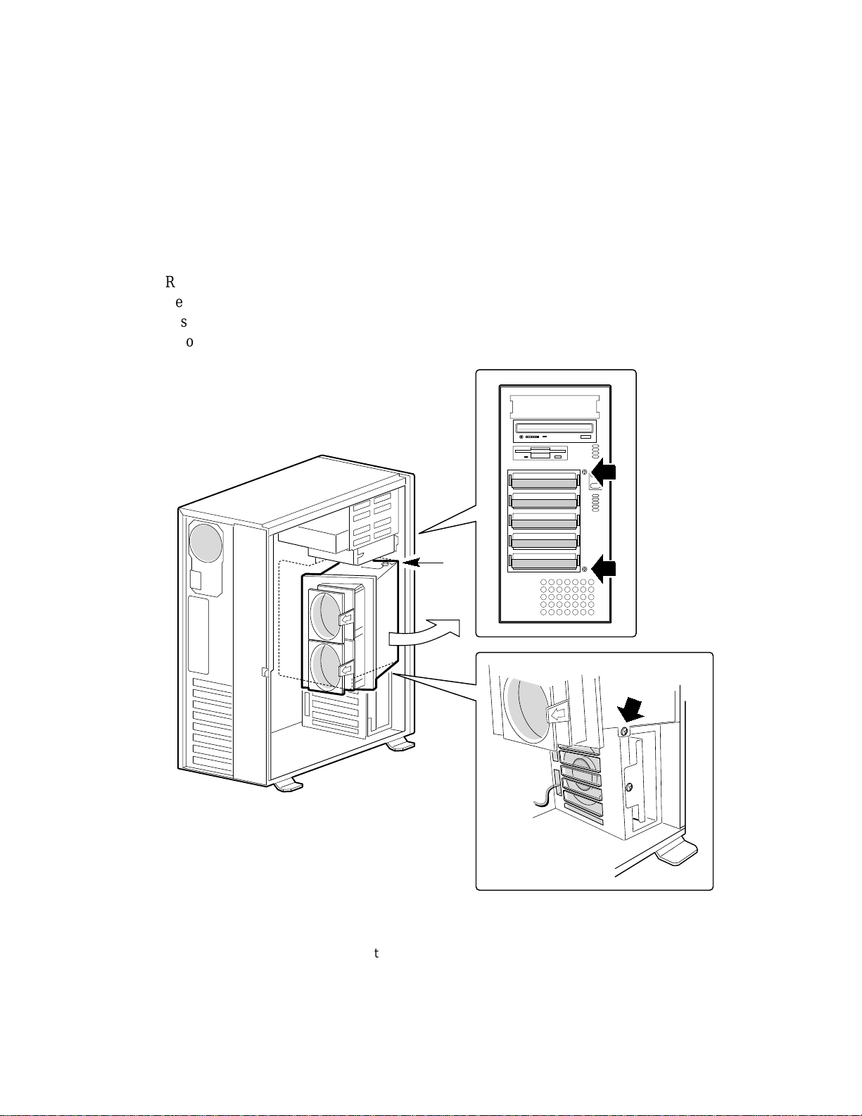
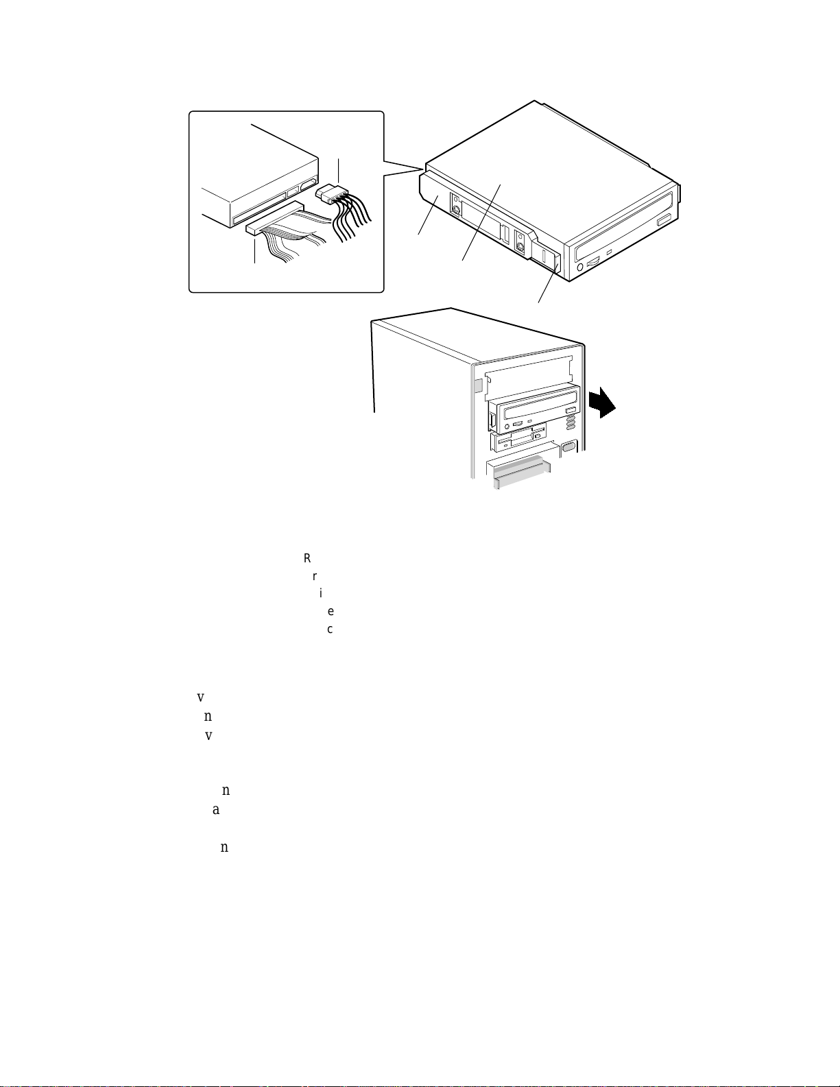
Removing the Hot-swap Bay
NOTE
✏
The hot-swap bay may be heavy if it is full of drives. It is not necessary to
remove the drives from the bay before removing the bay from the chassis.
However, we recommend you remove any drives in the bay before removing
the bay to minimize the risk of personal injury or property damage.
1.Remove the side cover. You do not need to remove the plastic front cover.
2.Remove the three screws holding the bay chassis.
3.Disconnect the power and data cables from the SCSI backplane.
4.Pivot the bay until it comes out of the chassis.
A
Figure 6. Removing the Hot-swap Bay
A.Pivot point
OM07043
18 Intel Astor II Server Chassis Subassembly Product Guide
Page 19
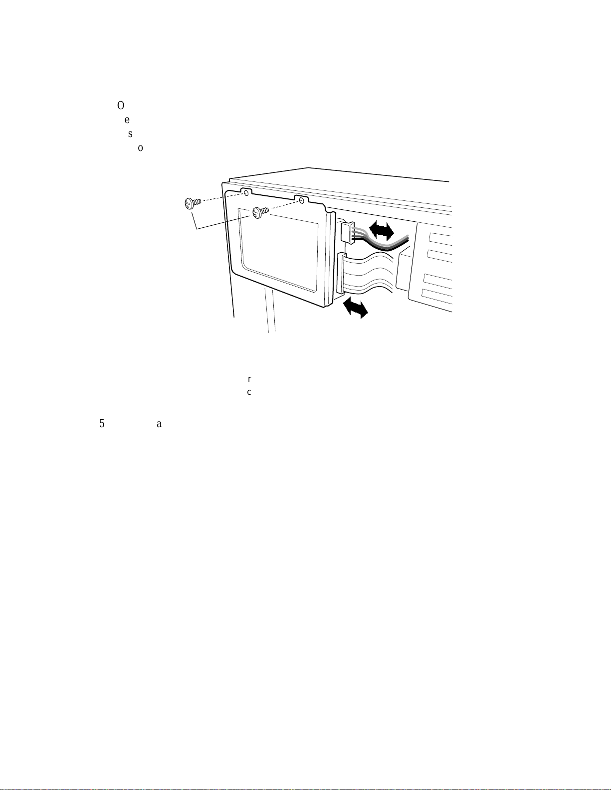
Removing the IDE Drive Bay
1.Observe the safety and ESD precautions at the beginning of this chapter.
2.Remove the side cover.
3.Disconnect the power and signal cables from any drives in the bay.
4.Remove and save the two screws at the top of the bay.
A
C
B
Figure 7. Disconnect Cables and Remove Screws
OM07560
A.Power cable
B.Data cable
C.Screws
5.Remove and save the screw in the flange at the bottom of the drive bay (see Figure 8, A).
6.Push the drive bay up and pull it out of the chassis. Do not swing it on its hinges, as the flange
may get caught in the fans mounted on the hot-swap bay.
Working Inside the System 19
Page 20
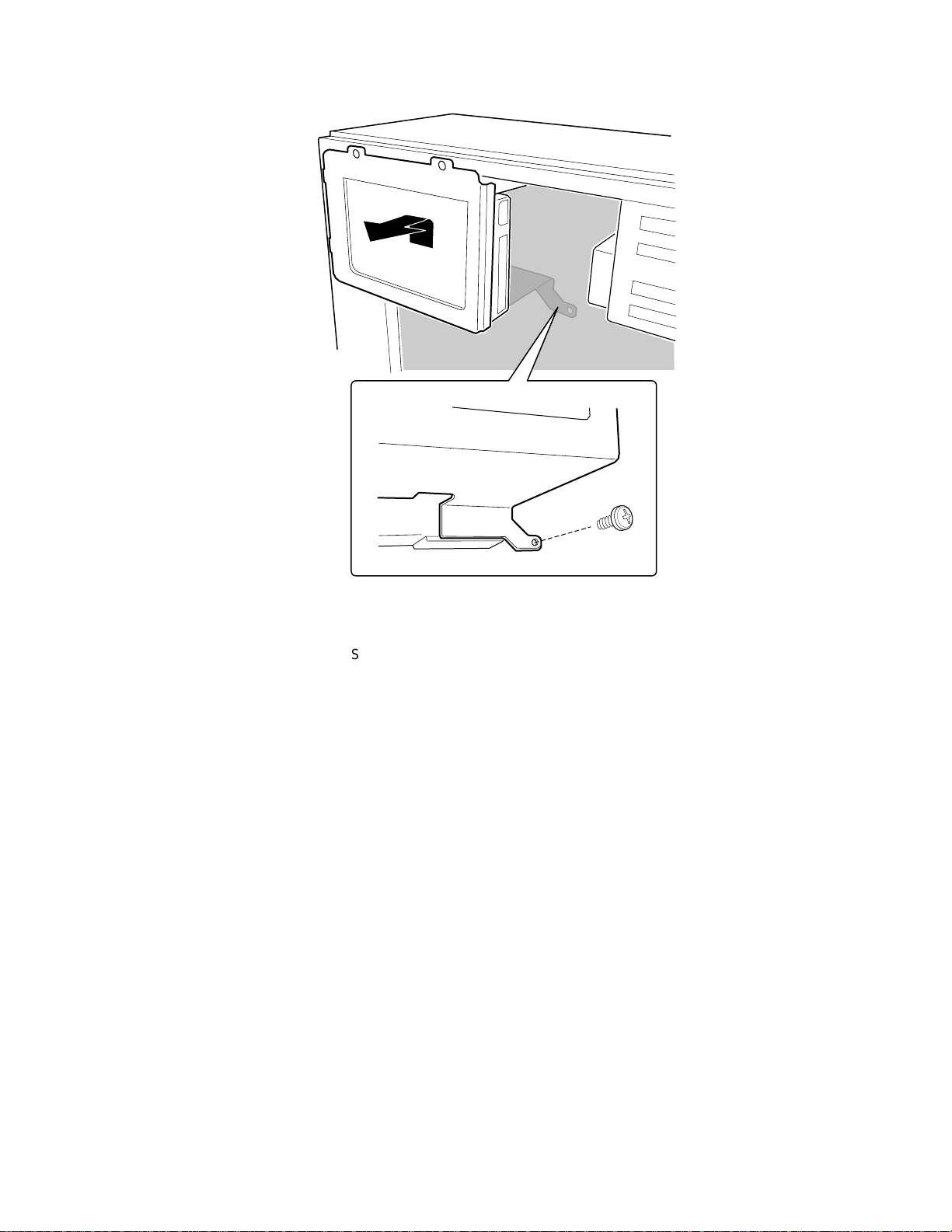
A.Screw
A
OM07561
Figure 8. IDE Hard Drive Bay
20 Intel Astor II Server Chassis Subassembly Product Guide
Page 21
Installing Server Board Clips and Bumpers
To support the server board in the Astor II chassis, you must install three rubber bumpers and
eleven or twelve standoff clips (depending on the server board you are installing).
1.Peel the adhesive backing from three rubber bumpers; stick the bumpers to the chassis wall
(see Figure 9, A).
2.Install eleven or twelve standoff clips in the chassis wall (see Figure 9, B). Gently pinch the
open end of each clip with needle-nosed pliers, insert into a slot on the chassis wall, and
release. Pressure holds the clip in place.
B
A
4.5"
7.75"
6.0"
3.0"
Figure 9. Rubber Bumper and Standoff Clip Placement
B.Rubber bumper
C.Standoff clip location
10.0"
OM07019
Working Inside the System 21
Page 22
I/O Shield
NOTE
✏
An ATX 2.01-compliant I/O shield should be provided with your server
board. The shield is required by Electromagnetic Interference (EMI)
regulations. It minimizes EMI and ensures proper cooling of the server. If
the shield does not fit the chassis, obtain a properly sized shield from the
chassis supplier.
The shield fits the rectangular opening near the power supply in the back of the chassis. The shield
has cutouts that match the external I/O connectors (e.g., keyboard and mouse).
1.Install the shield from inside the chassis. Orient the shield so that the cutouts align with the
corresponding I/O connectors on the server board.
2.Position one edge so that the dotted groove (A) is outside the chassis wall, and the lip of the
shield rests on the inner chassis wall.
3.Hold the shield in place, and push it into the opening until it is seated (B). Pressure holds the
shield in place.
A
B
OM06332a
Figure 10. Installing the I/O Shield
(typical shield shown)
Installing the Server Board
4.Position the board over the snap in standoff and threaded standoffs inside the chassis, and slide
it carefully toward the rear of the system until the I/O connectors protrude through the back
panel.
5.Press the board onto the snap in standoff, and insert one screw through one of the mounting
holes of the board and into a threaded standoff. Do not tighten the screw until the next step.
6.Insert the remaining screws through the mounting holes and into the threaded standoffs. Make
sure the board is properly seated, and then tighten all the screws. Take care to not tighten the
screws more the 6 inch-pounds.
7.Install your processors and memory. See your server board manual for instructions.
8.Connect the power cable to the server board. See your server board manual for the location of
the main power connector. Once it is firmly connected to the server board, bend the wires
towards the front of the chassis. This will help when you install the hot-swap bay.
22 Intel Astor II Server Chassis Subassembly Product Guide
Page 23
9.Connect the Front Panel cable from the top of the front panel to the server board. See your
server board manual for the location of the front panel connector. The cable from the bottom
of the front panel goes to the hot-swap backplane.
10.If you are going to install a diskette drive or any hard drives, attach the appropriate cables to
the server board. See your server board manual for the locations of data cable connectors.
Figure 11. Installing the Server Board
OM07048
(typical board shown)
Working Inside the System 23
Page 24

Installing a Chassis Intrusion Switch
Your server board probably has a chassis intrusion connector on it. However, we recommend that
you attach the chassis intrusion switch to the front panel.
1.Remove the side cover.
2.Remove the IDE drive bay.
3.Remove the hot-swap bay.
4.Position the switch so the screw hole lines up with the hole in the chassis.
5.Insert and tighten the screw.
6.There are three small holes in the sheet metal, two on the back and one in the top. Attach two
of the plastic clips to the cable and route it along the back of the chassis. Insert the plastic
clips into the holes along the back of the chassis. Attach the third clip to the cable and route
the cable between the power supply and the IDE bay. Insert the third clip into the hole in the
top sheet metal. Route the cable behind the 5.25-inch drive bay.
7.Connect the chassis intrusion switch cable to the front panel.
OM08475
Figure 12. Installing a Chassis Intrusion Switch
24 Intel Astor II Server Chassis Subassembly Product Guide
Page 25
Removing the Front Cover
1.Remove side cover.
2.Squeeze the two plastic tabs inside the front cover, and push them through the chassis slots.
3.Pull the left side of the cover out slightly, about 15, until the cover clears the power and reset
buttons. Slide the cover to the right until the tabs disengage from the chassis slots. Set the
cover aside.
Figure 13. Removing the Front Cover
OM07097
Working Inside the System 25
Page 26

Installing the Diskette Drive
1.Observe the safety and ESD precautions at the beginning of this chapter.
2.Remove the new 3.5-inch diskette drive from its protective wrapper, and place it component
side up on an antistatic surface. Record the drive model and serial numbers in your equipment
log.
3.Set any jumpers or switches according to the drive manufacturer’s instructions.
4.Slide the drive into the chassis.
5.Secure the drive to the 5.25-inch bay with the screws you removed earlier; tighten the screws
firmly.
6.Connect the signal and power cables to the drive.
B
A
Figure 14. Installing the Diskette Drive
A.Power cable
B.Signal cable
C.Chassis screws
C
Removing the Diskette Drive
1.Observe the safety and ESD precautions at the beginning of this chapter.
2.Remove the side cover.
3.Remove the front cover.
4.Disconnect the power cable and signal cable from the diskette drive.
5.Remove and save the screws that secure the diskette drive to the 5.25-inch drive bay.
6.Slide the drive forward and out of the system and place it component side up on an antistatic
surface. If not reinstalling the same drive, place it in an antistatic protective wrapper.
OM07052
26 Intel Astor II Server Chassis Subassembly Product Guide
Page 27

Hard Drives
Drive Cabling Considera tions
The number of devices you can install depends on:
The number supported by the bus
The number of physical drive bays available
The combination of SCSI and IDE devices
You should route cables to minimize airflow disruption. Air flows from the front to the rear of the
chassis. You should route IDE and diskette drive cables behind the hot-swap bay.
IDE Requirements
An 18-inch long IDE cable that supports two drives is standard in the system.
For proper IDE operation, note the cable length specified in the following figure. If no drives are
present on an IDE channel, the cable must be removed. If only one drive is installed, it must be
connected at the end of the cable.
12" 6"
Baseboard Drive 1 Drive 0
18"
OM05093
Figure 15. IDE Cable Dimensions
SCSI Requirements
All SCSI devices must be unterminated except the peripheral at the end of the SCSI cable. Hard
drives usually provide an active termination, while CD-ROM drives do not. The SCSI controller
on the server board is actively terminated. The SCSI hot-swap backplane provides termination and
SCSI IDs for drives connected to it.
Installing a Hard Drive into the IDE drive bay
The IDE drive bay provides space for two 1-inch high hard drives.
1.Observe the safety and ESD precautions at the beginning of this chapter.
2.Remove the IDE drive bay from the chassis.
3.Remove the drive from its protective wrapper, and place it on an antistatic surface.
4.Record the drive model and serial numbers in your equipment log.
5.Set any jumpers and/or switches on the drive according to the drive manufacturer’s
instructions.
6.Slide the drive into the drive bay so the screw holes in the drive and the bay line up. For the
best cooling, the component side of the drive should face away from the plate of the drive bay.
Working Inside the System 27
Page 28

7.Insert and tighten four screws (gold colored screws with washers are provided).
8.Install the IDE drive bay into the chassis.
OM07562
Figure 16. IDE Hard Drive
Removing a Hard Drive from the IDE Drive Bay
1.Observe the safety and ESD precautions at the beginning of this chapter. Also see the cabling
considerations on page 27.
2.Remove the IDE drive bay from the chassis.
3.Remove the four screws holding the hard drive in the bay.
4.Slide the hard drive out of the bay.
5.Reinstall the hard drive bay.
28 Intel Astor II Server Chassis Subassembly Product Guide
Page 29

Installing the IDE Drive Bay
1.Observe the safety and ESD precautions at the beginning of this chapter.
2.Place the drive bay into the chassis so its hinges are in their slots.
3.Move the drive bay down until the screw holes in the bay and the chassis line up.
4.Replace the two screws on the top of the bay (see Figure 17, C).
A
C
B
Figure 17. Disconnect Cables and Remove Screws
OM07560
A.Power cable
B.Data cable
C.Screws
5.Replace the screw in the flange at the bottom of the drive bay (see Figure 8, A, on page 20).
6.Connect data and power cables to any drives in the bay.
Working Inside the System 29
Page 30

Installing a 5.25-inch Peripheral Device
Two 5.25-inch half-height bays provide space for tape backup, CD-ROM, or other removable
media drives.
CAUTION
For several reasons, we recommend that you do NOT install hard drives in
the 5.25-inch bays: the drives cannot be properly cooled in this location; a
hard drive generates EMI and is more susceptible to ESD in this location.
NOTES
✏
System EMI integrity and cooling are both protected by having drives
installed in the bays or filler panels and EMI shields covering the bays.
When you install a drive, save the panel and shield to reinstall in case you
should later remove the drive and not reinstall one in the same bay.
It is important that your cabling and connections meet the SCSI bus
specification. Otherwise, the bus could be unreliable and data corruption
could occur or devices may not work at all. The SCSI bus needs to be
terminated at the end of the cable, and this is usually provided by the last
SCSI device on the cable.
1.Observe the safety and ESD precautions at the beginning of this chapter.
2.Remove the side and front system covers. Place the front cover on a flat surface.
3.Remove filler panel from the bay and set it aside.
4.Push the tab on the left side of the EMI metal shield to the right to disengage it from the
chassis. Save the shield.
C
A
Figure 18. Remove Filler Panels and EMI Shields
A.EMI shield
B.Filler panel
C.Tab
B
OM07099
30 Intel Astor II Server Chassis Subassembly Product Guide
Page 31

5.Remove the drive from its protective wrapper, and place it on an antistatic surface.
6.Record the drive model and serial numbers in your equipment log.
7.Set any jumpers and/or switches on the drive according to the drive manufacturer’s
instructions.
8.Using two screws (silver screws without washers are provided), attach each plastic slide rail
with its metal grounding plate to the drive.
9.Position the drive so the plastic slide rails engage in the bay guide rails. Push the drive into the
bay until the slide rails lock in place.
D
B
C
Figure 19. Snap-in Plastic Slide Rails
A.CD-ROM or other removable media device
B.Tab on slide rail
C.Screws (4)
D.Slide rails (2)
10.Connect a power cable to the drive.
11.Connect a signal cable to the drive.
A
OM07046
Working Inside the System 31
Page 32
D
B
E
Figure 20. Installing a Removable Media Device
A.Removable media device
B.Drive rail
C.Rail tab
D.Power cable
E.Typical SCSI signal cable
A
C
OM07036
Removing a 5.25-inch Peripheral Device
1.Observe the safety and ESD precautions at the beginning of this chapter.
2.Disconnect the power and signal cables from the drive.
3.The drive has two protruding plastic, snap in rails attached. Squeeze the rail tabs toward each
other as you carefully slide the drive forward out of the bay, and place it on an antistatic
surface.
4.Remove and save the four screws and two slide rails.
5.If you leave the bay empty, install a stainless steel EMI shield on the bay and a filler panel on
the front cover for proper cooling and airflow.
6.If you do not replace the device with another SCSI device, and it was installed at the end of the
SCSI signal cable, modify the cable and termination arrangement so that a proper termination
exists at the end of the cable (it can be a termination device only, not necessarily a SCSI
peripheral).
32 Intel Astor II Server Chassis Subassembly Product Guide
Page 33

Installing the Front Cover
1.Insert the plastic tabs on the front cover into the slots on the right of the chassis. Squeeze the
front panel and chassis together along the left side until the plastic tabs snap into their slots.
Installing the Hot-swap Bay
1.Tilt the bay into the chassis.
2.Connect the power and data cables to the SCSI backplane.
3.Install and tighten the three screws holding the bay to the chassis.
4.Install the side cover.
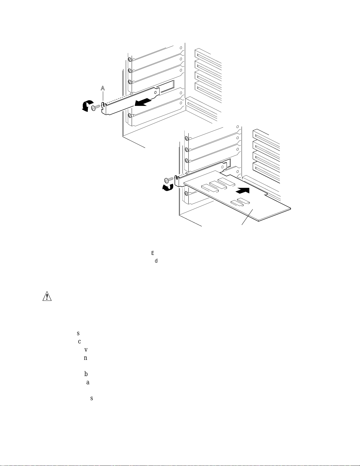
Installing an Add-in Board
CAUTIONS
Do not overload the server board by installing add-in boards that draw
excessive current.
Add-in boards can be extremely sensitive to ESD and always require careful
handling. After removing the board from its protective wrapper or from the
server board, place it component side up on a grounded, static free surface or
conductive foam pad—if available. Do not slide the board over any surface.
1.Remove side cover.
2.Remove and save the expansion slot screw and cover.
3.Remove add-in board from its protective wrapper. Be careful not to touch the components or
gold edge connectors. Place board component side up on an antistatic surface.
4.Record the type and serial number of the add-in board in your equipment log.
5.Set jumpers or switches according to the manufacturer’s instructions.
6.Hold board by its top edge or upper corners. Firmly press it into an expansion slot on the
server board. The tapered foot of the board retaining bracket must fit into the mating slot in
the expansion slot frame.
Install an ISA board component side UP.
Install a PCI board component side DOWN.
7.Align the rounded notch in the retaining bracket with the threaded hole in the frame. The
bracket fits the space that was occupied by the slot cover.
8.Use the screw removed earlier. Insert it into the threaded hole, and push the rounded notch
against the screw. Tighten it firmly to prevent the bracket from interfering with adjacent
brackets. Attach cables if necessary.
9.Reinstall the side cover.
Working Inside the System 33
Page 34
A
B
OM06425
Figure 21. Installing an Add-in Board
A.Expansion slot cover and screw
B.Add-in board, use same screw
Removing an Add-in Board
CAUTION
Slot covers must be installed on all vacant expansion slots. This maintains
the electromagnetic emissions characteristics of the system and ensures
proper cooling of system components.
1.Observe the safety and ESD precautions at the beginning of this chapter.
2.Disconnect any cables attached to the board you are removing.
3.Remove and save the screw from the board retaining bracket.
4.Holding the board by its top edge or upper corners, carefully pull it out. Do not scrape the
board against other components.
5.Store board in an antistatic protective wrapper.
6.If you are not reinstalling a board in the same slot, install a slot cover over the vacant slot. The
tapered foot of the cover must fit into the mating slot in the expansion slot frame.
7.Use the screw removed earlier. Insert it into the threaded hole, and push the rounded notch
against screw. Tighten it firmly to prevent the bracket from interfering with adjacent brackets.
34 Intel Astor II Server Chassis Subassembly Product Guide
Page 35
Installing the Side Cover
CAUTION
When you install the side cover, do not damage the EMI gaskets mounted on
the cover. Replace any damaged strips, or your system may not meet EMI
requirements.
1.Before replacing a side cover, check that you have not left loose tools or parts inside the
system.
2.Check that cables, add-in boards, and other components are properly installed.
3.Position the cover over the chassis so that the top row of tabs aligns with slots in the top of the
chassis. Slide the cover toward the front of the system until the cover tabs firmly engage in the
chassis.
4.Attach the cover to the chassis with the three screws you removed earlier, and tighten them
firmly.
5.To prevent unauthorized access inside the system, insert and lock a padlock through the metal
loop protruding through the slot in the back of the side cover.
6.Connect all external cables and the power cord to the system.
Working Inside the System 35
Page 36
Hot-swap Bay
The plastic front door covers a removable metal EMI cover that is hinged at the bottom. Plastic
drive carriers for 3.5-inch wide by 1-inch high drives allow easy hot-swapping of drives without
shutting down the system.
The backplane uses industry-standard 80-pin SCA2 connectors to support up to five industrystandard Ultra2/LVD SCA2 SCSI hard disk drives. The bays accept peripherals that consume up
to 17 watts of power and run at a maximum ambient temperature of 50 °C.
SCSI Hard Disk Drives
The system supports a variety of single ended or LVD (low voltage differential) SCSI SCA2
devices. Visit the support website for your server board for a list of approved single ended SCSI
SCA2 devices. http://support.intel.com/support/motherboards\server\
WARNING
The Ultra2/LVD SCSI hot-swap backplane requires installing LVD or
single ended SCSI devices in your system. Installing high voltage
differential (HVD) SCSI drive types can result in electrical damage to
the server board and the peripherals.
CAUTION
ESD can damage disk drives, add-in boards, and other components. This
server can withstand normal levels of environmental ESD while SCSI hard
disk drives are being swapped. However, we recommend doing all
procedures in this manual only at an ESD workstation. If one is not
available, you can provide some ESD protection by wearing an antistatic
wrist strap attached to chassis ground of the server—any unpainted metal
surface—when handling components.
For proper air flow and hard drive cooling, make sure that the paper baffles
included with the chassis are installed in any drive carriers that do not
contain drives. Fold the ends of the paper baffle up along the dotted lines.
Mounting a SCSI SCA2 Hard Disk Drive in a Plastic Carrier
1.Record the drive model and serial number in your equipment log.
2.Orient the drive so the connector is near the top surface of the drive, and place it on an
antistatic surface.
3.Place the plastic carrier on top of the drive.
4.Using four screws (silver screws with washers are supplied), attach the carrier to the drive.
36 Intel Astor II Server Chassis Subassembly Product Guide
Page 37

OM07035
Figure 22. Hard Disk Drive and Plastic Carrier
Installing a SCSI SCA2 Hard Disk Drive in the Hot-swap Bay
1.Open the plastic front door.
2.If there is a padlock installed on the metal EMI cover, remove it.
3.Pull the top of the metal EMI cover away from the chassis.
4.Position the drive/carrier assembly, locking tab to the left, so it engages the hot-swap bay
guide rails.
5.Gently push the assembly into the bay until it docks with the backplane connector and snaps
into place.
6.Close the metal EMI cover.
7.Close the plastic front door.
Working Inside the System 37
Page 38

Figure 23. Installing a Hard Disk Drive
Hot-swapping a SCSI SCA2 Hard Disk Drive
A bank of five yellow LEDs on the front panel monitors the drive status of each drive in the hotswap bay. When a yellow LED is on continuously, it is okay to hot-swap (replace) a bad drive
with a good one. You do not need to shut the system down to hot-swap a drive.
1.Open the plastic front door of the system.
2.Pull the top of the metal EMI cover away from the chassis.
3.Check the bank of yellow LEDs on the front panel to determine which drive is bad. Grasp that
drive’s plastic drive carrier, squeeze the tab on the carrier, and carefully slide the bad drive out
of the bay. Place the drive on an antistatic surface.
4.Position the new plastic carrier and drive assembly so that it engages the bay guide rails.
5.Gently push the drive into the bay until it docks with the backplane connector and snaps into
place.
6.Close the metal door.
7.Close the plastic front door.
OM07049
38 Intel Astor II Server Chassis Subassembly Product Guide
Page 39

Fans
For cooling and airflow, the system contains three removable chassis fans to cool the boards and
removable media drives. The integrated power supply fan provides more cooling and airflow.
NOTE
✏
The fan has two connectors on its cable. One is labeled “N440BX” and
should only be connected a system fan connector on the Intel N440BX
Server Board. The other connector is label “ATX” and can be connected to
any ATX compliant board.
Table 2. Fan Cable Connector Pinout
Pin ATX signal N440BX Signal Wire Color
1 Ground Ground Black
2 +12V SPEED Yellow
3 Speed +12 V red
Removing the Front Fan
1.Observe the safety and ESD precautions at the beginning this chapter.
2.Remove the side cover.
3.Disconnect the fan power cable connector from the fan header on the server board.
4.Remove the screw holding the fan bracket to the chassis.
5.Pull the fan bracket out of the chassis.
A
B
OM07050
Figure 24. Removing the Fan Bracket
A.Fan power cable
B.Notched metal tabs
Working Inside the System 39
Page 40

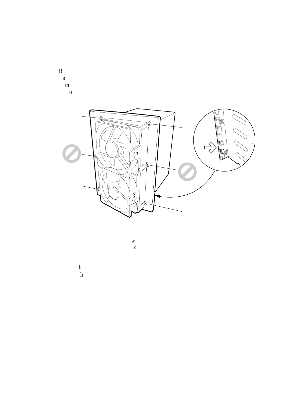
Installing the Front Fan
NOTE
✏
The removable fan pulls air from in front of the chassis so that it flows
across the boards and out the back. Thus, the fan must be oriented for the
correct airflow direction. If you place the fan so the label faces the back of
the chassis, this should provide the correct orientation. You can confirm this
by checking the embossed arrows on the side of the fan as you place it in its
bracket:
Arrow points horizontally toward back of chassis
Arrow points vertically up
Replace a failed fan with the same type as the one removed, with a
tachometer signal, or an approved fan. For a list of approved fans, contact
your distributor or customer service representative.
OM07564
Figure 25. Installing the Front Fan
1.Attach the fan to the bracket with two snap rivets.
2.Feed the fan’s power cable through the hole in the card guide.
3.Slide the fan bracket into the chassis. Make sure that the bottom of the bracket is set into the
notches on the metal tab.
4.Install and tighten the screw that holds the bracket to the chassis.
40 Intel Astor II Server Chassis Subassembly Product Guide
Page 41

Removing a Hot-swap Bay Fan
Figure 26. Removing the Hot-swap Bay Fan Bracket
1.Observe the safety and ESD precautions at the beginning this chapter.
2.Remove the side cover.
3.Disconnect the fan’s power cable from the SCSI backplane.
4.Snap the fan out of the plastic shroud.
A
OM07042
Installing a Hot-swap Bay Fan
1.Position the fan, label side facing away from the hot-swap bay, and snap it into the shroud.
2.Connect the fan’s power cable to the SCSI backplane (a fan in the bottom of the shroud
connects to the Fan 1 header; a fan in the top of the shroud connects to Fan 0 header).
3.Reinstall the side cover.
Working Inside the System 41
Page 42
Hot-swap Backplane
Removing the SCSI Backplane
1.Remove any hard drives installed in the hot-swap bay.
2.Remove the hot-swap bay from the chassis.
3.Remove the hot-swap bay fans.
4.Remove the four corner screws holding the plastic shroud and SCSI backplane to the hot-swap
bay. Do not remove the two center screws.
A
A
B
A
A
OM07042A
Figure 27. Removing the Plastic Shroud
A.Screws
B.Threaded tabs on hot-swap bay
5.Remove the plastic shroud and set it aside.
6.Remove the two center screws holding the SCSI backplane to the hot-swap bay.
7.Remove the SCSI backplane, and place it component side up on a nonconductive, static free
surface or in an antistatic bag.
42 Intel Astor II Server Chassis Subassembly Product Guide
Page 43

A
A
OM07053
Figure 28. Removing the SCSI Backplane
A.Screws
Installing the SCSI Backplane
1.Place the SCSI backplane component side to the hot-swap bay.
2.Insert and tighten the two center screws that hold the backplane to the hot-swap bay.
3.Place the plastic shroud on the back of the backplane.
4.Insert and tighten the four corner screws holding the plastic shroud and SCSI backplane to the
hot-swap bay.
5.Install two hot-swap bay fans.
Working Inside the System 43
Page 44

Front Panel Board
Removing the Front Panel Board
The front panel board contains the system controls and indicators. The board is mounted on a snap
on standoff and a threaded standoff inside the chassis.
1.Observe the safety and ESD precautions at the beginning of this chapter.
2.Remove the side cover.
3.Remove the hot-swap bay.
4.Remove and save the snap rivets holding the front panel board to the chassis.
5.Disconnect the data cables from the front panel.
6.Remove the front panel board from the system, and place it on an antistatic foam pad or a
grounded workstation.
OM07098
Figure 29. Removing the Front Panel Board
Installing the Front Panel Board
1.Position the front panel board over the tabs inside the chassis.
2.Reconnect the data cables to the front panel board.
3.Insert the snap rivets from the bottom, through the tabs and the front panel.
4.Reinstall the hot-swap bay.
5.Reinstall the side cover.
44 Intel Astor II Server Chassis Subassembly Product Guide
Page 45

3 Technical Reference
Power Supply Specifications
Input Voltages
The 300 watt power supply, designed to minimize EMI, provides sufficient power for a maximum
configuration of the server. The input voltage ranges are:
100-120 V at 50/60 Hz; 4.6 A maximum current
200-240 V at 50/60 Hz; 2.3 A maximum current
If a system is integrated to a fully configured condition, checking the input current rating will
provide an indication of whether the system is overloaded or not. The input current rating should
not exceed 4.6 amperes (for 100-120Vac) or 2.3 amperes (for 200-240Vac).
Output Voltages
The table below lists the total watts available for each voltage. Adjust your loads so that the
combined total wattage for your system configuration is less than 300 watts. For information
about calculating the power usage for your system configuration, see page 59.
Table 3. Power Supply Output Voltages
Maximum
Voltage
+3.3 V 16.0 A 52.8 W
+5.0 V 26.0 A 130.0 W
–5.0 V 0.25 A 1.25 W
+5V Standby 0.8 A 4.0 W
+12.0 V 10.0 A 13.0 A 120.0 W
–12.0 V 0.5 A 6.0 W
Continuous Current Peak Current Watts
CAUTION
Do not exceed a combined power output of 167 watts for the +5 V and +3.3 V
outputs. Exceeding a combined 167 watts will overload the power supply and
may cause the power supply to overheat and malfunction.
The ISA slot(s) on the system board are rated at a maximum of 4.5 amperes per slot. The ISA
specification recommends supporting an average of 2.0 amperes per slot. The average current
usage should not exceed 3.0 amperes per slot; that is, 15 watts.
The PCI slots on the system board are rated at a maximum of 5 amperes per slot. The maximum
power allowed for each slot is 20 watts at +5 volts. The average current usage per slot should not
exceed 3.0 amperes per slot; that is, 15 watts.
45
Page 46
Environmental Specifications
Table 4. Environmental Specifications
Temperature
Nonoperating
Operating
Humidity
Nonoperating
Operating wet bulb
Shock
Operating 2.0 g, 11 msec, 1/2 sine
Acoustic noise Typically <45 dBA at 18° to 24 °C (65° to 75 °F) with five internal hard disk
Electrostatic discharge (ESD) Tested to 20 kilovolts (kV); no component damage
AC Input Power
100-120 V
200-240 V
–40° to 70 °C (–55° to 150 °F)
10° to 35 °C (41° to 95 °F); derated 0.5 °C for every 1000 ft (305 m)
95% relative humidity (noncondensing) at 30 °C (86 °F)
Not to exceed 33 °C (91.4 °F) (with diskette drive or hard disk drive)
drives (measured at 1 meter from the system with the peripherals idle). The
noise of the variable speed system fan will increase with temperature and
power load. Your selection of peripherals may change the noise level.
100-120 V, 4.6 A, 50/60 Hz
200-240 V, 2.3 A, 50/60 Hz
46 Astor II Chassis Subassembly Product Guide
Page 47
SCSI Hot-swap Backplane Connectors
OM03878
1
68
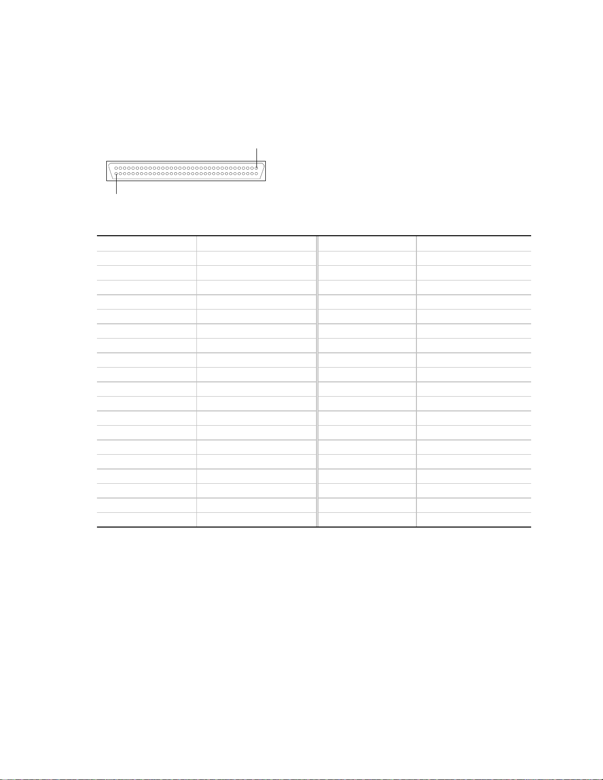
Ultra2/LVD SCSI 16-Bit Connector
Table 5. Wide/Fast SCSI 16-Bit Connector Pinout
Pin Signal Pin Signal
1-16 GND (ground) 49-50 GND (ground)
17 TERMPWR 51 TERMPWR
18 TERMPWR 52 TERMPWR
19 RESERVED 53 RESERVED
20-34 GND (ground) 54 GND (ground)
35 DB12_L 55 ATN_L
36 DB13_L 56 GND (ground)
37 DB14_L 57 BSY_L
38 DB15_L 58 ACK_L
39 DBP1_L 59 RST_L
40 DB0_L 60 MSG_L
41 DB1_L 61 SEL_L
42 DB2_L 62 CD_L
43 DB3_L 63 REQ_L
44 DB4_L 64 I/O_L
45 DB5_L 65 DB8_L
46 DB6_L 66 DB9_L
47 DB7_L 67 DB10_L
48 DBP_L 68 DB11_L
Technical Reference 47
Page 48

Ultra2/LVD SCA2 SCSI 16-Bit Connectors
1
OM04855
Table 6. Wide/Fast SCA2 SCSI 16-Bit Connector Pinout
Pin Signal Pin Signal
1-4 +12 V 25 DB 3_L
56 NC 26 DB 2_L
7 DB 11_L 27 DB 1_L
8 DB 10_L 28 DB 0_L
9 DB 9_L 29 DB P_L
10 DB 8_L 30 DB 15_L
11 I/O_L 31 DB 14_L
12 REQ_L 32 DB 13_L
13 C/D_L 33 DB 12_L
14 SEL_L 34-36 +5 V
15 MSG_L 37 SYNC
16 RST_L 38 MTRON_L
17 ACK_L 39 ID0_L
18 BSY_L 40 ID2_L
19 ATN_L 41 DRV PRES_L
20 DB P_L 4276 GND
21 DB 7_L 77 LEDC, DRV ACT_L
22 DB 6_L 78 DLYDST_L
23 DB 5_L 79 ID1_L
24 DB 4_L 80 ID3_L
48 Astor II Chassis Subassembly Product Guide
Page 49
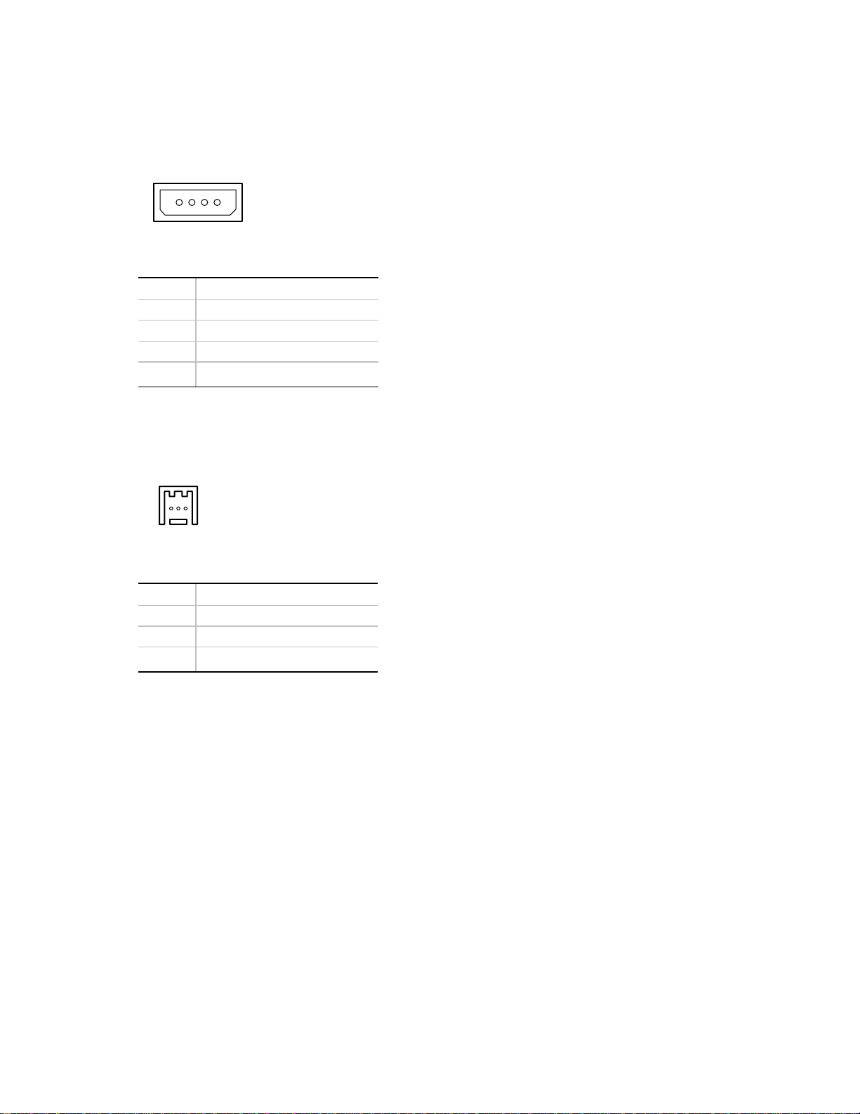
Power Connectors
The backplane power connectors are 4-pin shrouded plastic connectors with mechanical keying.
1234
OM04656
Table 7. Power Connector Pinout
Pin Signal
1 +12 V
2 Ground
3 Ground
4+5 V
Backplane Fan Connector
This connector provides power to the fan.
123
OM05211
Table 8. Backplane Fan Connector Pinout
Pin Signal
1 GND (ground)
2 SPEED
3 +12 V
Technical Reference 49
Page 50
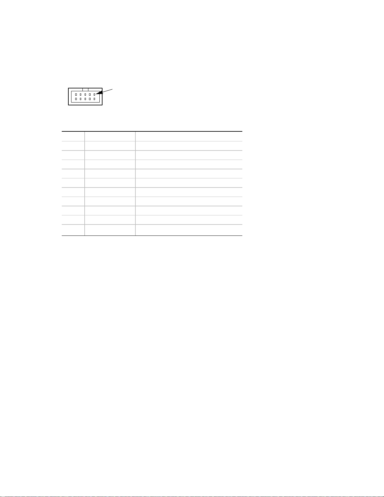
Front Panel Cable Connec tor
The front panel connector and cable provide the chassis wide IMB bus and the electrical path
between the drive fault indicators (LEDs) and the SCSI backplane that controls them.
1
OM04669
Table 9. Front Panel Connector Pinout
Pin Name Description
1 GND Electrical ground (0V)
2 I2C_SDA I2C SDA (Serial Data)
3 NC No Connect
4 I2C_SCL I2C Serial Clock
5 PRI_SEC_L Primary Secondary Backplane
6 FAULT1_L Fault signal for drive 1 (logical drive 0)
7 FAULT2_L Fault signal for drive 2 (logical drive 1)
8 FAULT3_L Fault signal for drive 3 (logical drive 2)
9 FAULT4_L Fault signal for drive 4 (logical drive 3)
10 FAULT5_L Fault signal for drive 5 (logical drive 4)
50 Astor II Chassis Subassembly Product Guide
Page 51

4 Regulatory Information
WARNING
You must adhere to the assembly instructions in this guide to ensure
and maintain compliance with existing product regulations. Use only
the described, regulated components specified in this guide. Use of
other products / components will void the UL listing of the product, will
most likely void other compliance markings provided, and may result in
noncompliance with product regulations in the region(s) in which the
product is sold.
Regulatory Compliance
This subassembly, when correctly integrated per this guide, complies with the following safety and
electromagnetic compatibility (EMC) regulations.
Safety Compliance
UL 1950 - CSA 950-95, 3rd Edition, July 28, 1995
The Standard for Safety of Information Technology Equipment including Electrical Business
Equipment. (USA and Canada). This product has been evaluated and complies to UL1950 – CSA
950-95 3
used, the system will be deemed to comply with UL 1950 2
rd
Edition. However, if a UL1950 2nd Edition modem telecommunications add-in card is
nd
Edition/CSA950-93.
EN 60 950, 2nd Edition, 1992 (with Amendments 1, 2, and 3)
The Standard for Safety of Information Technology Equipment including Electrical Business
Equipment. (European Union)
IEC60 950, 2nd edition, 1991 (with Amendments 1, 2, 3 and 4)
The Standard for Safety of Information Technology Equipment including Electrical Business
Equipment. (International)
EMKO-TSE (74-SEC) 207/94
Summary of Nordic deviations to EN 60 950. (Norway, Sweden, Denmark, and Finland)
51
Page 52

EMC Compliance
FCC Class B
Title 47 of the Code of Federal Regulations, Parts 2 and 15, Subpart B, pertaining to unintentional
radiators. (USA)
CISPR 22, 2nd Edition, 1993, Amendment 1, 1995
Limits and methods of measurement of Radio Interference Characteristics of Information
Technology Equipment. (International)
EN 55 022, 1995
Limits and methods of measurement of Radio Interference Characteristics of Information
Technology Equipment. (Europe)
EN 50 082-1, 1992
Generic Immunity Standard. Currently, compliance is determined via testing to IEC 801-2, -3
and -4. (Europe)
VCCI Class B (ITE)
Implementation Regulations for Voluntary Control of Radio Interference by Data Processing
Equipment and Electronic Office Machines. (Japan)
ICES-003, Issue 2
Interference Causing Equipment Standard, Digital Apparatus. (Canada)
Australian Communication Authority (ACA)
Australian C-tick mark, limits and methods of measurement radio interference characteristics of
information technology equipment to ASNZS 3548 (Australian requirements based on CISPR 22
requirements).
New Zealand Ministry of Commerce
Australian C-tick mark, limits and methods of measurement radio interference characteristics of
information technology equipment to ASNZS 3548 (New Zealand requirements based on
CISPR 22 requirements). New Zealand authorities accept ACA C-Tick Compliance Mark.
52 Intel Astor II Server Chassis Subassembly Product Guide
Page 53

Regulatory Compliance Markings
This Astor II chassis subassembly is provided with the following Product Certification Markings.
UL and cUL Listing Marks
CE Mark
Australian C-Tick Mark
German GS Mark
The CE marking on this product indicates that it is in compliance with the European
community’s EMC (89/336/EEC) and low voltage directives (73/23/EEC)
NEMKO Mark
FCC, Class B (Declaration of Conformity)
ICES-003 (Canada Compliance Marking)
VCCI Class B
Electromagnetic Compatibility Notice (USA)
This equipment has been tested and found to comply with the limits for a Class B digital device,
pursuant to Part 15 of the FCC Rules. These limits are designed to provide reasonable protection
against harmful interference in a residential installation. This equipment generates, uses, and can
radiate radio frequency energy and, if not installed and used in accordance with the instructions,
may cause harmful interference to radio communications. However, there is no guarantee that
interference will not occur in a particular installation. If this equipment does cause harmful
interference to radio or television reception, which can be determined by turning the equipment off
and on; the user is encouraged to try to correct the interference by one or more of the following
measures:
Reorient or relocate the receiving antenna.
Increase the separation between the equipment and the receiver.
Connect the equipment into an outlet on a circuit different from that to which the receiver is
connected.
Consult the dealer or an experienced radio/TV technician for help.
Any changes or modifications not expressly approved by the grantee of this device could void the
user’s authority to operate the equipment. The customer is responsible for ensuring compliance of
the modified product.
Only peripherals (computer input/output devices, terminals, printers, etc.) that comply with FCC
Class B limits may be attached to this computer product. Operation with noncompliant peripherals
is likely to result in interference to radio and TV reception.
All cables used to connect to peripherals must be shielded and grounded. Operation with cables,
connected to peripherals, that are not shielded and grounded may result in interference to radio and
TV reception.
Regulatory Information 53
Page 54

NOTE
✏
If a Class A device is installed within this system, then the system is to be
considered a Class A system. In this configuration, operation of this
equipment in a residential area is likely to cause harmful interference.
FCC Declaration of Conformity
Product Type: AST2
This device complies with Part 15 of the FCC Rules. Operation is subject to the following two
conditions: 1) This device may not cause harmful interference, and 2) this device must accept any
interference received, including interference that may cause undesired operation.
Intel Corporation
5200 N.E. Elam Young Parkway
Hillsboro, OR 97124-6497
Phone: 1-800-628-8686
Cet appareil numérique respecte les limites bruits radioélectriques applicables aux appareils
numériques de Classe B prescrites dans la norme sur le matériel brouilleur: “Appareils
Numériques”, NMB-003 édictée par le Ministre Canadian des Communications.
(English translation of the notice above) This digital apparatus does not exceed the Class B limits
for radio noise emissions from digital apparatus set out in the interference causing equipment
standard entitled “Digital Apparatus,” ICES-003 of the Canadian Department of Communications.
Electromagnetic Compatibility Notices (International)
(English translation of the notice above) This is a Class B product based on the standard of the
Voluntary Control Council For Interference (VCCI) from Information Technology Equipment. If
this is used near a radio or television receiver in a domestic environment, it may cause radio
interference. Install and use the equipment according to the instruction manual.
When used near a radio or TV receiver, it may become the cause of radio interference.
Read the instructions for correct handling.
This equipment has been tested for radio frequency emissions and has been verified to meet
CISPR 22 Class B.
54 Intel Astor II Server Chassis Subassembly Product Guide
Page 55
Installation Safety Instructions
CAUTION
Integration of this assembly shall be done only by technically qualified
personnel.
Follow these guidelines to meet and maintain safety and product regulatory
requirements when integrating this Astor II chassis subassembly.
Read and adhere to all of these instructions and the instructions supplied
with this assembly. If you do not follow these instructions, the UL listing
will be void, and the product will most likely be noncompliant with other
regional product laws and regulations.
The following warning is provided on the server board configuration label, which is provided with
the Intel server board boxed product. There is insufficient space on the server board to place this
label. Therefore, the label must be placed permanently on the inside of the chassis, as close to the
battery as possible.
WARNING
Danger of explosion if battery is incorrectly replaced. Replace with only
the same or equivalent type recommended by the manufacturer.
Dispose of used batteries according to the manufacturer’s instructions.
ADVARSEL!
Lithiumbatteri - Eksplosionsfare ved fejlagtig håndtering. Udskiftning
må kun ske med batteri af samme fabrikat og type. Levér det brugte
batteri tilbage til leverandøren.
ADVARSEL!
Lithiumbatteri - Eksplosjonsfare. Ved utskifting benyttes kun batteri
som anbefalt av apparatfabrikanten. Brukt batteri returneres
apparatleverandøren.
VARNING
Explosionsfara vid felaktigt batteribyte. Använd samma batterityp eller
en ekvivalent typ som rekommenderas av apparattillverkaren. Kassera
använt batteri enligt fabrikantens instruktion.
VAROITUS
Paristo voi räjähtää, jos se on virheellisesti asennettu. Vaihda paristo
ainoastaan laitevalmistajan suosittelemaan tyyppiin. Hävitä käytetty
paristo valmistajan ohjeiden mukaisesti.
Regulatory Information 55
Page 56

Use Only for Intended Applica tions
This product was evaluated as Information Technology Equipment (ITE) that may be installed in
offices, homes, schools, computer rooms and similar locations. The suitability of this product for
other Product Categories and Environments other than ITE applications, (such as medical,
industrial, alarm systems, and test equipment) may require further evaluation.
When you integrate this subassembly, observe all warnings and cautions in the Installation Guide.
To avoid injury, be careful of:
Sharp pins on connectors
Sharp pins on printed circuit assemblies
Rough edges and sharp corners on the chassis
Hot components (like processors, voltage regulators, and heat sinks)
Damage to wires that could cause a short circuit
WARNING
Do not open the power supply. Risk of electric shock and burns from
high voltage and rapid overheating. Refer servicing of the power supply
to qualified technical personnel.
To maintain the UL listing and compliance to other regulatory certifications and/or declarations,
the following regulated components must be used, and conditions adhered to. Information for
system configurations can be found through Intel’s web address (http://www.intel.com). If you do
not have access to Intel’s web address please contact your local Intel representative.
Astor II chassis (chassis is provided with power supply and fans)UL listed.
Server boardyou must use an Intel UL Recognized Server board.
Add-in boardsmust have a printed wiring board flammability rating of minimum UL94V-1.
Add-in boards containing external power connectors and/or lithium batteries must be UL
Recognized or UL Listed. Add-in boards containing modem telecommunication circuitry must
be UL Listed.
Peripheral storage devicesmust be UL recognized or UL listed accessory and TUV or VDE
licensed. Maximum capacity for this chassis is 8 devices; maximum of any one device is
17W. Total system configuration is not to exceed maximum loading conditions of power
supply.
When using a UL Recognized Peripheral Storage Device, the plastic bezel must be made
of a UL recognized plastic with a flammability rating of 5V.
56 Intel Astor II Server Chassis Subassembly Product Guide
Page 57

A Equipment Log and Worksheets
Equipment Log
Use the blank equipment log provided here to record information about your system. You will
need some of this information when you run the SSU.
Item Manufacturer Name and Model Number Serial Number Date Installed
Chassis
Server board
Processor speed
and cache
Video display
Video Controller
Keyboard
Mouse
Diskette drive A
Diskette drive B
Tape drive
CD-ROM drive
SCSI disk drive 1
SCSI disk drive 2
SCSI disk drive 3
SCSI disk drive 4
SCSI disk drive 5
continued
57
Page 58

Equipment Log
Item Manufacturer Name and Model Number Serial Number Date Installed
IDE disk drive 1
IDE disk drive 2
(continued)
58 Intel Astor II Server Chassis Subassembly Product Guide
Page 59
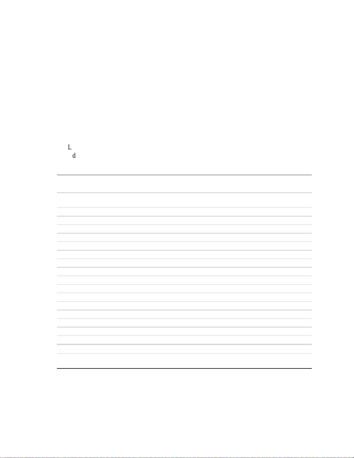
Current Usage
As an overall current usage limitation on the power supply, do not exceed a combined power
output of 167 watts for the +5 V and +3.3 V outputs.
Calculating Power Usage
The total combined wattage for the system configuration must be less than 300 watts. Use the
two worksheets in this section to calculate the total used by your system. For current and voltage
requirements of add-in boards and peripherals, see your vendor documents.
Worksheet, Calculating DC Power Usage
1.List the current for each board and device in the appropriate voltage level column.
2.Add the currents in each column. Then go to the next worksheet.
Table 10. Power Usage Worksheet 1
Current (maximum) at voltage level:
Device +3.3 V +5 V –5 V +12 V –12 V
Boards, processors, and memory (get
totals from your board manual)
SCSI backplane
Front panel board
3.5-inch diskette drive
CD-ROM drive
Second 5.25-inch device
1st hot-swap hard drive
2nd hot-swap hard drive
3rd hot-swap hard drive
4th hot-swap hard drive
5th hot-swap hard drive
1st IDE hard drive
2nd IDE hard drive
Cooling fan 1, 92 mm 0.4 A
Cooling fan 2, 92 mm 0.4 A
Cooling fan 3, 92 mm 0.4 A
Total Current
Maximum Ratings (for comparison) 16.0 A 26.0 A 0.25 A 10.0 A 0.5 A
Equipment Log and Worksheets 59
Page 60
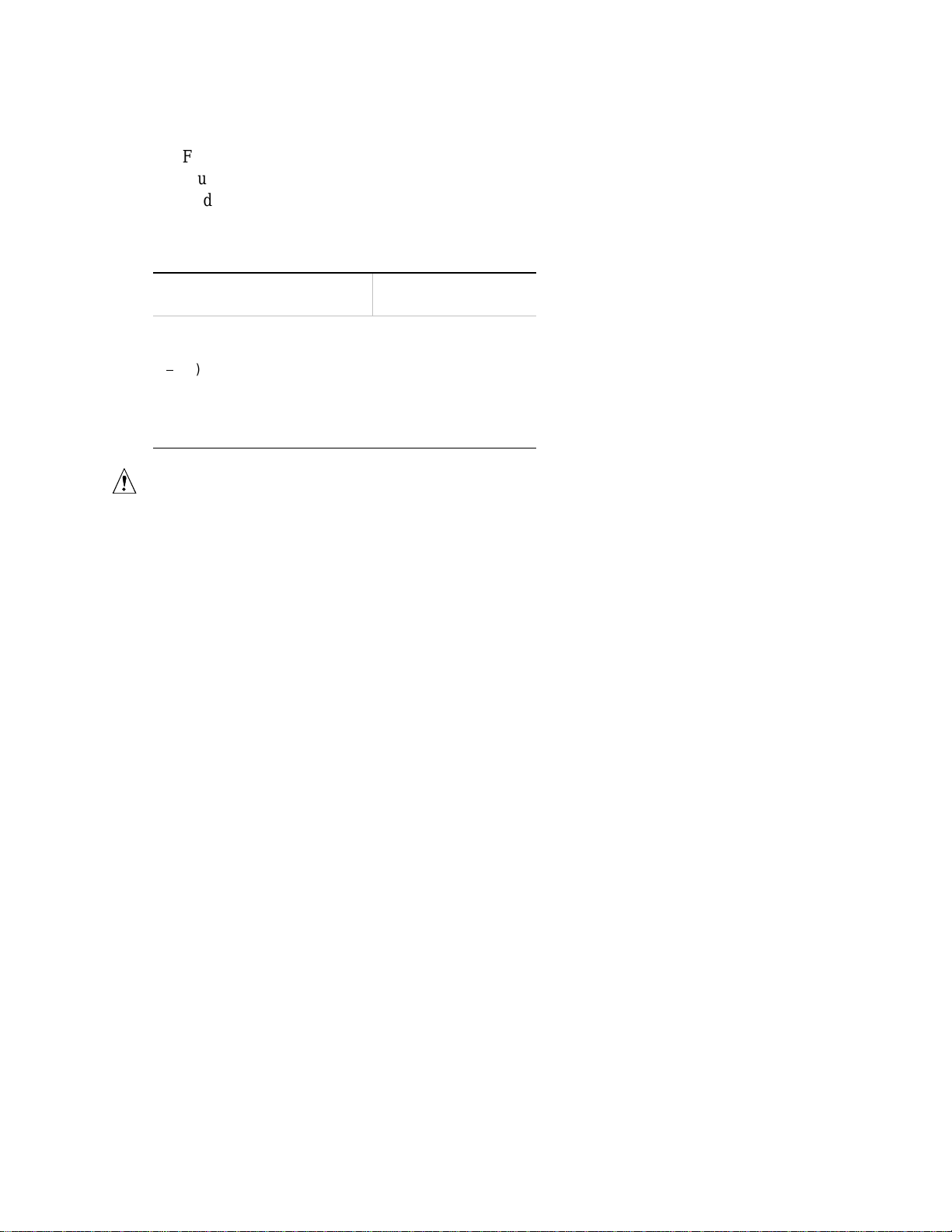
Worksheet, Total Combined Power Used by the System
1.From the previous worksheet, enter the total current for each column.
2.Multiply the voltage by the total current to get the total wattage for each voltage level.
3.Add the total wattage for each voltage level to arrive at a total combined power usage on the
power supply.
Table 11. Power Usage Worksheet 2
Voltage level and total current
(V X A = W)
(+3.3 V) X (______ A) ________ W
(+5 V) X (______ A) ________ W
(5 V) X (______ A) ________ W
(+12 V) X (______ A) ________ W
(–12 V) X (______ A) ________ W
Total Combined Wattage ________ W
CAUTION
As an overall current usage limitation on the power supply, do not exceed a
combined power output of 167 watts for the +5 V and +3.3 V outputs.
Total Watts
for each voltage level
60 Intel Astor II Server Chassis Subassembly Product Guide
Page 61

B Warnings
WARNING: English (US)
AVERTISSEMENT: Français
WARNUNG: Deutsch
AVVERTENZA: Italiano
ADVERTENCIAS: Español
61
Page 62

WARNING: English (US)
The power supply in this product contains no user-serviceable parts. There may be more
than one supply in this product. Refer servicing only to qualified personnel.
Do not attempt to modify or use the supplied AC power cord if it is not the exact type
required. A product with more than one power supply will have a separate AC power cord
for each supply.
The power button on the system does not turn off system AC power. To remove AC power
from the system, you must unplug each AC power cord from the wall outlet or power supply.
SAFETY STEPS: Whenever you remove the chassis covers to access the inside of the
system, follow these steps:
1.Turn off all peripheral devices connected to the system.
2.Turn off the system by pressing the power button.
3.Unplug all AC power cords from the system or from wall outlets.
4.Label and disconnect all cables connected to I/O connectors or ports on the back of the
system.
5.Provide some electrostatic discharge (ESD) protection by wearing an antistatic wrist
strap attached to chassis ground of the system—any unpainted metal surface—when
handling components.
6.Do not operate the system with the chassis covers removed.
After you have completed the six SAFETY steps above, you can remove the system covers.
To do this:
1.Unlock and remove the padlock from the back of the system if a padlock has been
installed.
2.Remove and save all screws from the covers.
3.Remove the covers.
For proper cooling and airflow, always reinstall the chassis covers before turning on the
system. Operating the system without the covers in place can damage system parts. To
install the covers:
1.Check first to make sure you have not left loose tools or parts inside the system.
2.Check that cables, add-in boards, and other components are properly installed.
3.Attach the covers to the chassis with the screws removed earlier, and tighten them
firmly.
4.Insert and lock the padlock to the system to prevent unauthorized access inside the
system.
5.Connect all external cables and the AC power cord(s) to the system.
continued
62 Astor II Chassis Subassembly Product Guide
Page 63

WARNING: English
(continued)
A microprocessor and heat sink may be hot if the system has been running. Also, there
may be sharp pins and edges on some board and chassis parts. Contact should be made
with care. Consider wearing protective gloves.
Danger of explosion if the battery is incorrectly replaced. Replace only with the same or
equivalent type recommended by the equipment manufacturer. Discard used batteries according to manufacturer’s instructions.
The system is designed to operate in a typical office environment. Choose a site that is:
Clean and free of airborne particles (other than normal room dust).
Well ventilated and away from sources of heat including direct sunlight.
Away from sources of vibration or physical shock.
Isolated from strong electromagnetic fields produced by electrical devices.
In regions that are susceptible to electrical storms, we recommend you plug your
system into a surge suppresser and disconnect telecommunication lines to your modem
during an electrical storm.
Provided with a properly grounded wall outlet.
Provided with sufficient space to access the power supply cords, because they serve as
the product’s main power disconnect.
Warnings 63
Page 64

AVERTISSEMENT: Français
Le bloc d'alimentation de ce produit ne contient aucune pièce pouvant être réparée par
l'utilisateur. Ce produit peut contenir plus d'un bloc d'alimentation. Veuillez contacter un
technicien qualifié en cas de problème.
Ne pas essayer d'utiliser ni modifier le câble d'alimentation CA fourni, s'il ne correspond pas
exactement au type requis. Le nombre de câbles d'alimentation CA fournis correspond au
nombre de blocs d'alimentation du produit.
Notez que le commutateur CC de mise sous tension /hors tension du panneau avant
n'éteint pas l'alimentation CA du système. Pour mettre le système hors tension, vous devez
débrancher chaque câble d'alimentation de sa prise.
CONSIGNES DE SÉCURITÉ - Lorsque vous ouvrez le boîtier pour accéder à l’intérieur du
système, suivez les consignes suivantes :
1.Mettez hors tension tous les périphériques connectés au système.
2.Mettez le système hors tension en mettant l’interrupteur général en position OFF
(bouton-poussoir).
3.Débranchez tous les cordons d’alimentation c.a. du système et des prises murales.
4.Identifiez et débranchez tous les câbles reliés aux connecteurs d’E-S ou aux accès
derrière le système.
5.Pour prévenir les décharges électrostatiques lorsque vous touchez aux composants,
portez une bande antistatique pour poignet et reliez-la à la masse du système (toute
surface métallique non peinte du boîtier).
6.Ne faites pas fonctionner le système tandis que le boîtier est ouvert.
Une fois TOUTES les étapes précédentes accomplies, vous pouvez retirer les panneaux du
système. Procédez comme suit :
1.Si un cadenas a été installé sur à l’arrière du système, déverrouillez-le et retirez-le.
2.Retirez toutes les vis des panneaux et mettez-les dans un endroit sûr.
3.Retirez les panneaux.
Afin de permettre le refroidissement et l’aération du système, réinstallez toujours les
panneaux du boîtier avant de mettre le système sous tension. Le fonctionnement du
système en l’absence des panneaux risque d’endommager ses pièces. Pour installer les
panneaux, procédez comme suit :
1.Assurez-vous de ne pas avoir oublié d’outils ou de pièces démontées dans le système.
2.Assurez-vous que les câbles, les cartes d’extension et les autres composants sont bien
installés.
3.Revissez solidement les panneaux du boîtier avec les vis retirées plus tôt.
4.Remettez le cadenas en place et verrouillez-le afin de prévenir tout accès non autorisé
à l’intérieur du système.
5.Rebranchez tous les cordons d’alimentation c. a. et câbles externes au système.
suite
64 Astor II Chassis Subassembly Product Guide
Page 65

AVERTISSEMENT: Français
Le microprocesseur et le dissipateur de chaleur peuvent être chauds si le système a été
sous tension. Faites également attention aux broches aiguës des cartes et aux bords
tranchants du capot. Nous vous recommandons l'usage de gants de protection.
Danger d'explosion si la batterie n'est pas remontée correctement. Remplacer uniquement
avec une batterie du même type ou d'un type équivalent recommandé par le fabricant.
Disposez des piles usées selon les instructions du fabricant.
Le système a été conçu pour fonctionner dans un cadre de travail normal. L'emplacement
choisi doit être :
Propre et dépourvu de poussière en suspension (sauf la poussière normale).
Bien aéré et loin des sources de chaleur, y compris du soleil direct.
A l'abri des chocs et des sources de vibrations.
Isolé de forts champs électromagnétiques géenérés par des appareils électriques.
Dans les régions sujettes aux orages magnétiques il est recomandé de brancher votre
système à un supresseur de surtension, et de débrancher toutes les lignes de
télécommunications de votre modem durant un orage.
Muni d'une prise murale correctement mise à la terre.
Suffisamment spacieux pour vous permettre d'accéder aux câbles d'alimentation (ceux-
ci étant le seul moyen de mettre le système hors tension).
(suite)
Warnings 65
Page 66

WARNUNG: Deutsch
Benutzer können am Netzgerät dieses Produkts keine Reparaturen vornehmen. Das
Produkt enthält möglicherweise mehrere Netzgeräte. Wartungsarbeiten müssen von
qualifizierten Technikern ausgeführt werden.
Versuchen Sie nicht, das mitgelieferte Netzkabel zu ändern oder zu verwenden, wenn es
sich nicht genau um den erforderlichen Typ handelt. Ein Produkt mit mehreren Netzgeräten
hat für jedes Netzgerät ein eigenes Netzkabel.
Der Wechselstrom des Systems wird durch den Ein-/Aus-Schalter für Gleichstrom nicht
ausgeschaltet. Ziehen Sie jedes Wechselstrom-Netzkabel aus der Steckdose bzw. dem
Netzgerät, um den Stromanschluß des Systems zu unterbrechen.
SICHERHEISMASSNAHMEN: Immer wenn Sie die Gehäuseabdeckung abnehmen um an
das Systeminnere zu gelangen, sollten Sie folgende Schritte beachten:
1.Schalten Sie alle an Ihr System angeschlossenen Peripheriegeräte aus.
2.Schalten Sie das System mit dem Hauptschalter aus.
3.Ziehen Sie den Stromanschlußstecker Ihres Systems aus der Steckdose.
4.Auf der Rückseite des Systems beschriften und ziehen Sie alle Anschlußkabel von den
I/O Anschlüssen oder Ports ab.
5.Tragen Sie ein geerdetes Antistatik Gelenkband, um elektrostatische Ladungen (ESD)
über blanke Metallstellen bei der Handhabung der Komponenten zu vermeiden.
6.Schalten Sie das System niemals ohne ordnungsgemäß montiertes Gehäuse ein.
Nachdem Sie die oben erwähnten ersten sechs SICHERHEITSSCHRITTE durchgeführt
haben, können Sie die Abdeckung abnehmen, indem Sie:
1.Öffnen und entfernen Sie die Verschlußeinrichtung (Padlock) auf der Rückseite des
Systems, falls eine Verschlußeinrichtung installiert ist.
2.Entfernen Sie alle Schrauben der Gehäuseabdeckung.
3.Nehmen Sie die Abdeckung ab.
Zur ordnungsgemäßen Kühlung und Lüftung muß die Gehäuseabdeckung immer wieder vor
dem Einschalten installiert werden. Ein Betrieb des Systems ohne angebrachte Abdeckung
kann Ihrem System oder Teile darin beschädigen. Um die Abdeckung wieder anzubringen:
1.Vergewissern Sie sich, daß Sie keine Werkzeuge oder Teile im Innern des Systems
zurückgelassen haben.
2.Überprüfen Sie alle Kabel, Zusatzkarten und andere Komponenten auf
ordnungsgemäßen Sitz und Installation.
3.Bringen Sie die Abdeckungen wieder am Gehäuse an, indem Sie die zuvor gelösten
Schrauben wieder anbringen. Ziehen Sie diese gut an.
4.Bringen Sie die Verschlußeinrichtung (Padlock) wieder an und schließen Sie diese, um
ein unerlaubtes Öffnen des Systems zu verhindern.
5.Schließen Sie alle externen Kabel und den AC Stromanschlußstecker Ihres Systems
wieder an.
Fortsetzung
66 Astor II Chassis Subassembly Product Guide
Page 67

WARNUNG: Deutsch
Der Mikroprozessor und der Kühler sind möglicherweise erhitzt, wenn das System in Betrieb
ist. Außerdem können einige Platinen und Gehäuseteile scharfe Spitzen und Kanten
aufweisen. Arbeiten an Platinen und Gehäuse sollten vorsichtig ausgeführt werden. Sie
sollten Schutzhandschuhe tragen.
Bei falschem Einsetzen einer neuen Batterie besteht Explosionsgefahr. Die Batterie darf
nur durch denselben oder einen entsprechenden, vom Hersteller empfohlenen Batterietyp
ersetzt werden. Entsorgen Sie verbrauchte Batterien den Anweisungen des Herstellers
entsprechend.
Das System wurde für den Betrieb in einer normalen Büroumgebung entwickelt. Der
Standort sollte:
sauber und staubfrei sein (Hausstaub ausgenommen);
gut gelüftet und keinen Heizquellen ausgesetzt sein (einschließlich direkter
keinen Erschütterungen ausgesetzt sein;
keine starken, von elektrischen Geräten erzeugten elektromagnetischen Felder
in Regionen, in denen elektrische Stürme auftreten, mit einem
mit einer geerdeten Wechselstromsteckdose ausgerüstet sein;
über ausreichend Platz verfügen, um Zugang zu den Netzkabeln zu gewährleisten, da
(Fortsetzung)
Sonneneinstrahlung);
aufweisen;
Überspannungsschutzgerät verbunden sein; während eines elektrischen Sturms sollte
keine Verbindung der Telekommunikationsleitungen mit dem Modem bestehen;
der Stromanschluß des Produkts hauptsächlich über die Kabel unterbrochen wird.
Warnings 67
Page 68
AVVERTENZA: Italiano
Rivolgersi ad un tecnico specializzato per la riparazione dei componenti dell'alimentazione
di questo prodotto. È possibile che il prodotto disponga di più fonti di alimentazione.
Non modificare o utilizzare il cavo di alimentazione in c.a. fornito dal produttore, se non
corrisponde esattamente al tipo richiesto. Ad ogni fonte di alimentazione corrisponde un
cavo di alimentazione in c.a. separato.
L’interruttore attivato/disattivato nel pannello anteriore non interrompe l’alimentazione in c.a.
del sistema. Per interromperla, è necessario scollegare tutti i cavi di alimentazione in c.a.
dalle prese a muro o dall’alimentazione di corrente.
PASSI DI SICUREZZA: Qualora si rimuovano le coperture del telaio per accedere
all’interno del sistema, seguire i seguenti passi:
1.Spegnere tutti i dispositivi periferici collegati al sistema.
2.Spegnere il sistema, usando il pulsante spento/acceso dell’interruttore del sistema.
3.Togliere tutte le spine dei cavi del sistema dalle prese elettriche.
4.Identificare e sconnettere tutti i cavi attaccati ai collegamenti I/O od alle prese installate
sul retro del sistema.
5.Qualora si tocchino i componenti, proteggersi dallo scarico elettrostatico (SES),
portando un cinghia anti-statica da polso che è attaccata alla presa a terra del telaio del
sistema – qualsiasi superficie non dipinta – .
6.Non far operare il sistema quando il telaio è senza le coperture.
Dopo aver seguito i sei passi di SICUREZZA sopracitati, togliere le coperture del telaio del
sistema come seque:
1.Aprire e rimuovere il lucchetto dal retro del sistema qualora ve ne fosse uno installato.
2.Togliere e mettere in un posto sicuro tutte le viti delle coperture.
3.Togliere le coperture.
Per il giusto flusso dell’aria e raffreddamento del sistema, rimettere sempre le coperture del
telaio prima di riaccendere il sistema. Operare il sistema senza le coperture al loro proprio
posto potrebbe danneggiare i componenti del sistema. Per rimettere le coperture del telaio:
1.Controllare prima che non si siano lasciati degli attrezzi o dei componenti dentro il
sistema.
2.Controllare che i cavi, dei supporti aggiuntivi ed altri componenti siano stati installati
appropriatamente.
3.Attaccare le coperture al telaio con le viti tolte in precedenza e avvitarle strettamente.
4.Inserire e chiudere a chiave il lucchetto sul retro del sistema per impedire l’accesso non
autorizzato al sistema.
5.Ricollegare tutti i cavi esterni e le prolunghe AC del sistema.
continua
68 Astor II Chassis Subassembly Product Guide
Page 69
AVVERTENZA: Italiano
Se il sistema è stato a lungo in funzione, il microprocessore e il dissipatore di calore
potrebbero essere surriscaldati. Fare attenzione alla presenza di piedini appuntiti e parti
taglienti sulle schede e sul telaio. È consigliabile l'uso di guanti di protezione.
Esiste il pericolo di un esplosione se la pila non viene sostituita in modo corretto. Utilizzare
solo pile uguali o di tipo equivalente a quelle consigliate dal produttore. Per disfarsi delle
pile usate, seguire le istruzioni del produttore.
Il sistema è progettato per funzionare in un ambiente di lavoro tipo. Scegliere una
postazione che sia:
Pulita e libera da particelle in sospensione (a parte la normale polvere presente
Ben ventilata e lontana da fonti di calore, compresa la luce solare diretta.
Al riparo da urti e lontana da fonti di vibrazione.
Isolata dai forti campi magnetici prodotti da dispositivi elettrici.
In aree soggette a temporali, è consigliabile collegare il sistema ad un limitatore di
Dotata di una presa a muro correttamente installata.
Dotata di spazio sufficiente ad accedere ai cavi di alimentazione, i quali rappresentano
(continua)
nell'ambiente).
corrente. In caso di temporali, scollegare le linee di comunicazione dal modem.
il mezzo principale di scollegamento del sistema.
Warnings 69
Page 70

ADVERTENCIAS: Español
El usuario debe abstenerse de manipular los componentes de la fuente de alimentación de
este producto, cuya reparación debe dejarse exclusivamente en manos de personal técnico
especializado. Puede que este producto disponga de más de una fuente de alimentación.
No intente modificar ni usar el cable de alimentación de corriente alterna, si no corresponde
exactamente con el tipo requerido.
El número de cables suministrados se corresponden con el número de fuentes de
alimentación de corriente alterna que tenga el producto.
Nótese que el interruptor activado/desactivado en el panel frontal no desconecta la
corriente alterna del sistema. Para desconectarla, deberá desenchufar todos los cables de
corriente alterna de la pared o desconectar la fuente de alimentación.
INSTRUCCIONES DE SEGURIDAD: Cuando extraiga la tapa del chasis para acceder al
interior del sistema, siga las siguientes instrucciones:
1.Apague todos los dispositivos periféricos conectados al sistema.
2.Apague el sistema presionando el interruptor encendido/apagado.
3.Desconecte todos los cables de alimentación CA del sistema o de las tomas de
corriente alterna.
4.Identifique y desconecte todos los cables enchufados a los conectores E/S o a los
puertos situados en la parte posterior del sistema.
5.Cuando manipule los componentes, es importante protegerse contra la descarga
electrostática (ESD). Puede hacerlo si utiliza una muñequera antiestática sujetada a la
toma de tierra del chasis — o a cualquier tipo de superficie de metal sin pintar.
6.No ponga en marcha el sistema si se han extraído las tapas del chasis.
Después de completar las seis instrucciones de SEGURIDAD mencionadas, ya puede
extraer las tapas del sistema. Para ello:
1.Desbloquee y extraiga el bloqueo de seguridad de la parte posterior del sistema, si se
ha instalado uno.
2.Extraiga y guarde todos los tornillos de las tapas.
3.Extraiga las tapas.
Para obtener un enfriamiento y un flujo de aire adecuados, reinstale siempre las tapas del
chasis antes de poner en marcha el sistema. Si pone en funcionamiento el sistema sin las
tapas bien colocadas puede dañar los componentes del sistema. Para instalar las tapas:
1.Asegúrese primero de no haber dejado herramientas o componentes sueltos dentro del
sistema.
2.Compruebe que los cables, las placas adicionales y otros componentes se hayan
instalado correctamente.
3.Incorpore las tapas al chasis mediante los tornillos extraídos anteriormente,
tensándolos firmemente.
4.Inserte el bloqueo de seguridad en el sistema y bloquéelo para impedir que pueda
accederse al mismo sin autorización.
5.Conecte todos los cables externos y los cables de alimentación CA al sistema.
continúa
70 Astor II Chassis Subassembly Product Guide
Page 71
ADVERTENCIAS: Español
Si el sistema ha estado en funcionamiento, el microprocesador y el disipador de calor
pueden estar aún calientes. También conviene tener en cuenta que en el chasis o en el
tablero puede haber piezas cortantes o punzantes. Por ello, se recomienda precaución y el
uso de guantes protectores.
Existe peligro de explosión si la pila no se cambia de forma adecuada. Utilice solamente
pilas iguales o del mismo tipo que las recomendadas por el fabricante del equipo. Para
deshacerse de las pilas usadas, siga igualmente las instrucciones del fabricante.
El sistema está diseñado para funcionar en un entorno de trabajo normal. Escoja un lugar:
Limpio y libre de partículas en suspensión (salvo el polvo normal).
Bien ventilado y alejado de fuentes de calor, incluida la luz solar directa.
Alejado de fuentes de vibración.
Aislado de campos electromagnéticos fuertes producidos por dispositivos eléctricos.
En regiones con frecuentes tormentas eléctricas, se recomienda conectar su sistema a
un eliminador de sobrevoltage y desconectar el módem de las líneas de
telecomunicación durante las tormentas.
Provisto de una toma de tierra correctamente instalada.
Provisto de espacio suficiente como para acceder a los cables de alimentación, ya que
éstos hacen de medio principal de desconexión del sistema.
(continúa)
Warnings 71
Page 72

72 Astor II Chassis Subassembly Product Guide
Page 73

C Warranty
Limited Warranty for Intel® Server Chassis Subassembly Products
Intel warrants that the Products (defined herein as the Intel® chassis subassembly and all of its
various components and software delivered with or as part of the Products) to be delivered
hereunder, if properly used and installed, will be free from defects in material and workmanship
and will substantially conform to Intel’s publicly available specifications for a period of three (3)
years after the date the Product was purchased from an Intel authorized distributor. Software of
any kind delivered with or as part of products is expressly provided “as is” unless specifically
provided for otherwise in any software license accompanying the software.
If any Product furnished by Intel which is the subject of this Limited Warranty fails during the
warranty period for reasons covered by this Limited Warranty, Intel, at its option, will:
REPAIR the Product by means of hardware and/or software; OR
REPLACE the Product with another Product; OR
REFUND the then-current value of the Product if Intel is unable to repair or replace the
Product.
If such Product is defective, transportation charges for the return of Product to buyer within the
USA will be paid by Intel. For all other locations, the warranty excludes all costs of shipping,
customs clearance, and other related charges. Intel will have a reasonable time to make repairs or
to replace Product or to refund the then-current value of the Product.
In no event will Intel be liable for any other costs associated with the replacement or repair of
Product, including labor, installation or other costs incurred by buyer.
This Limited Warranty, and any implied warranties that may exist under state law, apply only to
the original purchaser of the Product.
Extent of Limited Warranty
Intel does not warrant that Products to be delivered hereunder, whether delivered stand-alone or
integrated with other Products, including without limitation semiconductor components, will be
free from design defects or errors known as “errata”. Current characterized errata are available
upon request.
This Limited Warranty does not cover damages due to external causes, including accident,
problems with electrical power, usage not in accordance with product instructions, misuse, neglect,
alteration, repair, improper installation, or improper testing.
73
Page 74

Warranty Limitations and Exclusions
These warranties replace all other warranties, expressed or implied including, but not limited to,
the implied warranties of merchantability and fitness for a particular purpose. Intel makes no
expressed warranties beyond those stated here. Intel disclaims all other warranties, expressed or
implied including, without limitation, implied warranties of merchantability and fitness for a
particular purpose. Some jurisdictions do not allow the exclusion of implied warranties, so this
limitation may not apply.
All expressed and implied warranties are limited in duration to the limited warranty period. No
warranties apply after that period. Some jurisdictions do not allow limitations on how long an
implied warranty lasts, so this limitation may not apply to you.
Limitations of Liability
Intel’s responsibility under this, or any other warranty, implied or expressed, is limited to repair,
replacement or refund, as set forth above. These remedies are the sole and exclusive remedies for
any breach of warranty. Intel is not responsible for direct, special, incidental, or consequential
damages resulting from any breach of warranty under another legal theory including, but not
limited to, lost profits, downtime, goodwill, damage to or replacement of equipment and property,
and any costs of recovering, reprogramming, or reproducing any program or data stored in or used
with a system containing this product. Some jurisdictions do not allow the exclusion or limitation
of incidental or consequential damages, so the above limitations or exclusions may not apply to
you.
This limited warranty gives you specific legal rights, and you may also have other rights that vary
from jurisdiction to jurisdiction.
Any and all disputes arising under or related to this Limited Warranty shall be adjudicated in the
following forums and governed by the following laws: for the United States of America, Canada,
North America and South America, the forum shall be Santa Clara, California, USA and the
applicable law shall be that of the State of California, USA; for the Asia Pacific region, the forum
shall be Singapore and the applicable law shall be that of Singapore; for Europe and the rest of the
world, the forum shall be London and the applicable law shall be that of the United Kingdom.
In the event of any conflict between the English language version and any other translated
version(s) of this Limited Warranty, the English language version shall control.
74 Intel Astor II Server Chassis Subassembly Product Guide
Page 75

How to Obtain Warranty Service
To obtain warranty service for this Product, you may contact Intel or your authorized distributor.
North AmericaCall Intel at 1-800-628-8686 during the warranty period during normal business
hours (pacific time), excluding holidays. Please be prepared to provide: (1) your name, address,
and telephone numbers; (2) model name and serial number of the Product; (3) an explanation of
the problem. The customer service representative may need additional information from you
depending on the nature of the problem.
In Europe, Asia, or South AmericaContact your original authorized distributor for warranty
service.
Any replacement Product is warranted under this written warranty and is subject to the same
limitations and exclusions for the remainder of the original warranty period.
Telephone Support
If you can’t find the information you need on Intel’s World Wide Web site (http://www.intel.com),
call your local distributor or an Intel Customer Support representative.
Customer Support
Country
United States 1-900-555-5800 7:00 - 17:00 $2.50/minute
United States &
Canada
European
Community
English:
Francaise:
Deutsch:
Italiano:
Asia-Pacific
Australia:
Hong Kong:
Korea:
Manila:
PRC:
Singapore:
Taiwan:
Everywhere else +916-377-7000 7:00 - 17:00 PST Credit card calls
Telephone Number Hours (Monday-Friday) Billing
1-800-404-2284 7:00 - 17:00 PST Credit card calls
$25.00/incident
+44-131-458-6847
+44-131-458-6848
+44-131-458-6954
+44-131-458-6951
+1-800-649-931
+852-2-844-4456
+822-767-2595
+886-2-718-9915
+852-2-844-4456
+65-831-1311
+886-2-718-9915
UK time
8:00 - 17:00 (M, Th, F)
8:00 - 16:00 (Tues - W)
Singapore local time
Oct-April: 6:00 - 16:00
April-Oct: 5:00 - 16:00
Credit Card Calls $25.00/incident
Levied in local currency at the
applicable credit card exchange rate
plus applicable VAT
Credit card calls $25.00/incident
$25.00/incident
Warranty 75
Page 76

Returning a Defective Product
Before returning any product, call your authorized dealer/distribution authority.
From Europe:
in English +44 1793 431144
in French +44 1793 421777
in German +44 1793 421333
All other locations: +(503) 264-7000
If the customer support group verifies that your product is defective, you will receive a Return
Material Authorization (RMA) number to place on the outer package of the product. Intel can not
accept any product without an RMA number on the package.
76 Intel Astor II Server Chassis Subassembly Product Guide
 Loading...