

Page 1
User’s Guide
®
Intel
Wireless Gateway II
Share
Broadband
with
all your PCs
Page 2

Copyright
The Intel®Wireless Gateway II User’s Guide as well as the software
described in it, is furnished under license and may only be used or copied in
accordance with the terms of the license. The information in this document is
furnished for informational use only, is subject to change without notice, and
should not be construed as a commitment by Intel Corporation. Intel assumes
no responsibility or liability for any errors or inaccuracies that may appear in
this document or any software that may be provided in association with this
document.
Except as permitted by such license, no part of this document may be
reproduced, stored in a retrieval system, or transmitted in any form or by any
means without the express written consent of Intel Corporation.
Information in this document is provided in connection with Intel products. No
license, express or implied, by estoppel or otherwise, to any intellectual
property rights is granted by this document. Except as provided in Intel's
Terms and Conditions of Sale for such products, Intel assumes no liability
whatsoever, and Intel disclaims any express or implied warranty, relating to
sale and/or use of Intel products including liability or warranties relating to
fitness for a particular purpose, merchantability, or infringement of any patent,
copyright or other intellectual property right. Intel products are not intended for
use in medical, life saving, or life sustaining applications.
Intel may make changes to specifications and product descriptions at any
time, without notice.
Intel, the Intel logo, and AnyPoint are trademarks or registered trademarks of
Intel Corporation or its subsidiaries in the United States and other countries.
*Other names and brands may be claimed as the property of others.
Copyright © 2002, Intel Corporation. All rights reserved.
Intel Corporation, 5200 NE Elam Young Parkway, Hillsboro, OR 97214-6497
Rev. 0.03, April 22, 2002
Page 3

Contents
Chapter 1 – Overview 1
Decide how to set up the Intel
FeaturesoftheIntelWirelessGatewayII.................3
Verify system and service requirements ..................4
Alookatthegatewayhardware........................5
Configurationsoftwareandsettings.....................9
Accessingtheconfigurationsoftware....................9
Wheretofindmoreinformation........................12
Chapter 2 – Setting Up the Gateway on a Network 13
Planning your network ..............................14
Connecting the gateway to an Ethernet hub or switch . .....14
Configuringthegatewayasanaccesspoint .............16
Installing wireless adapters on other PCs................20
Using Windows* XP Client Configuration Manager . . . .....21
Configuring the adapter .............................22
Chapter 3 – Changing the Gateway Settings 23
Opening the gateway configuration software .............24
Viewing your connection status .......................25
Viewingmorestatusdetails ..........................25
Printingyourgatewaysettings ........................25
Changing your wireless settings .......................26
Changing or disabling your encryption settings ...........28
Changing your device settings ........................32
Savingsettingsandrestartingyourgateway .............37
®
WirelessGatewayII........2
Chapter 4 – Using the Advanced Feature Set 39
Accessingadvancedfeatures.........................40
Changing your gateway password .....................40
Changing your advanced wireless settings...............41
Settingyourtransferrate ............................42
Setting your operating channel ........................42
iii
Page 4

Contents
Usingsystemtools.................................42
Establishingroutingprotocols.........................43
Refining DHCP server addressing .....................45
Assigningvirtualserversettings.......................46
Usingaccesscontrolfeatures.........................50
Changing your gateway IP address ....................51
IP addressing in network adapters .....................52
UniversalPlugandPlay.............................53
Chapter 5 – Troubleshooting 55
Problemsandsolutions..............................56
Ifallelsefails .....................................69
Reading the gateway indicator lights ...................70
Reading settings and device status ....................70
Using firmware troubleshooting tips ....................71
Using the system tools on your gateway ................71
Chapter 6 – Glossary 75
Glossary.........................................76
Chapter 7 – Specifications 82
Technicalspecifications .............................83
Chapter 8 – Regulatory Compliance Statements 85
Safetycompliancestatement.........................86
Emissionscompliancestatements .....................86
RFexposurecompliancestatements...................87
Canadian compliance statements......................87
European Union compliance statements ................87
Product Ecology Statements..........................89
Chapter 9 – Index 91
iv
Page 5

Chapter 1
Overview
This chapter provides a basic overview of the features of
the Intel
service requirements, and explains where to find more
information, if needed.
What’s in this chapter:
■ Decide how to set up the Intel
■ Features of the Intel Wireless Gateway II
■ A look at the gateway hardware
■ Configuration software and settings
■ Where to find more information
®
Wireless Gateway II, lists its system and
®
Wireless Gateway II
1
Page 6
Chapter 1 – Overview
Decide how to set up the Intel
There are several ways to set up your Intel®Wireless
Gateway II. The methods depend on whether you want
to:
• Set up a new network
• Add the gateway to an existing network
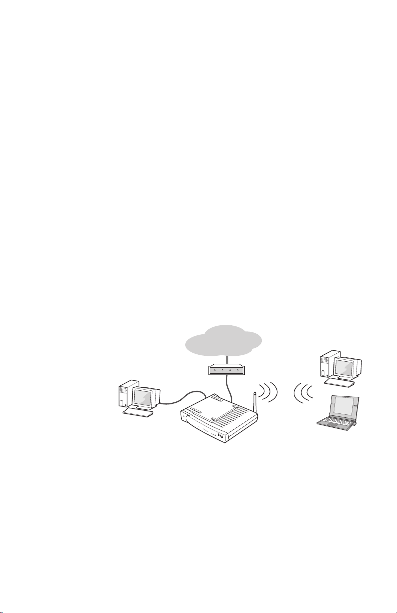
Overview of a
new network
The gateway lets you share an Internet connection
among all PCs. You can connect up to sixteen wireless
PCs and up to 4 Ethernet devices to share the Internet
connection. Each PC must have either:
• An 802.11b (Wi-Fi*) adapter
or
• An Ethernet adapter
The following diagram shows how such a network might
look.
®
Wireless Gateway II
Internet
P
o
w
e
r
S
L
ys
in
t
k
em
In
A
t
c
e
t
r
i
v
n
i
e
ty
t
1
W
i
re
l
e
ss
2
3
4
E
th
e
r
n
e
t
Wi
r
e
l
e
s
s
G
at
e
w
ay
II
You can also create an entirely wireless network of
desktop and laptop PCs. It is not a requirement to have
an Ethernet-connected PC attached to the gateway. In
the previous diagram, eliminate the wired PC. The
gateway manages communication between all PCs and
the Internet, as well as resource sharing (drives and
printers) between PCs. This is an excellent way to create
2
Page 7
Chapter 1 – Overview
a standalone wireless network in your home or small
office.
The instructions for setting up a new network are covered
in the Installation Guide.
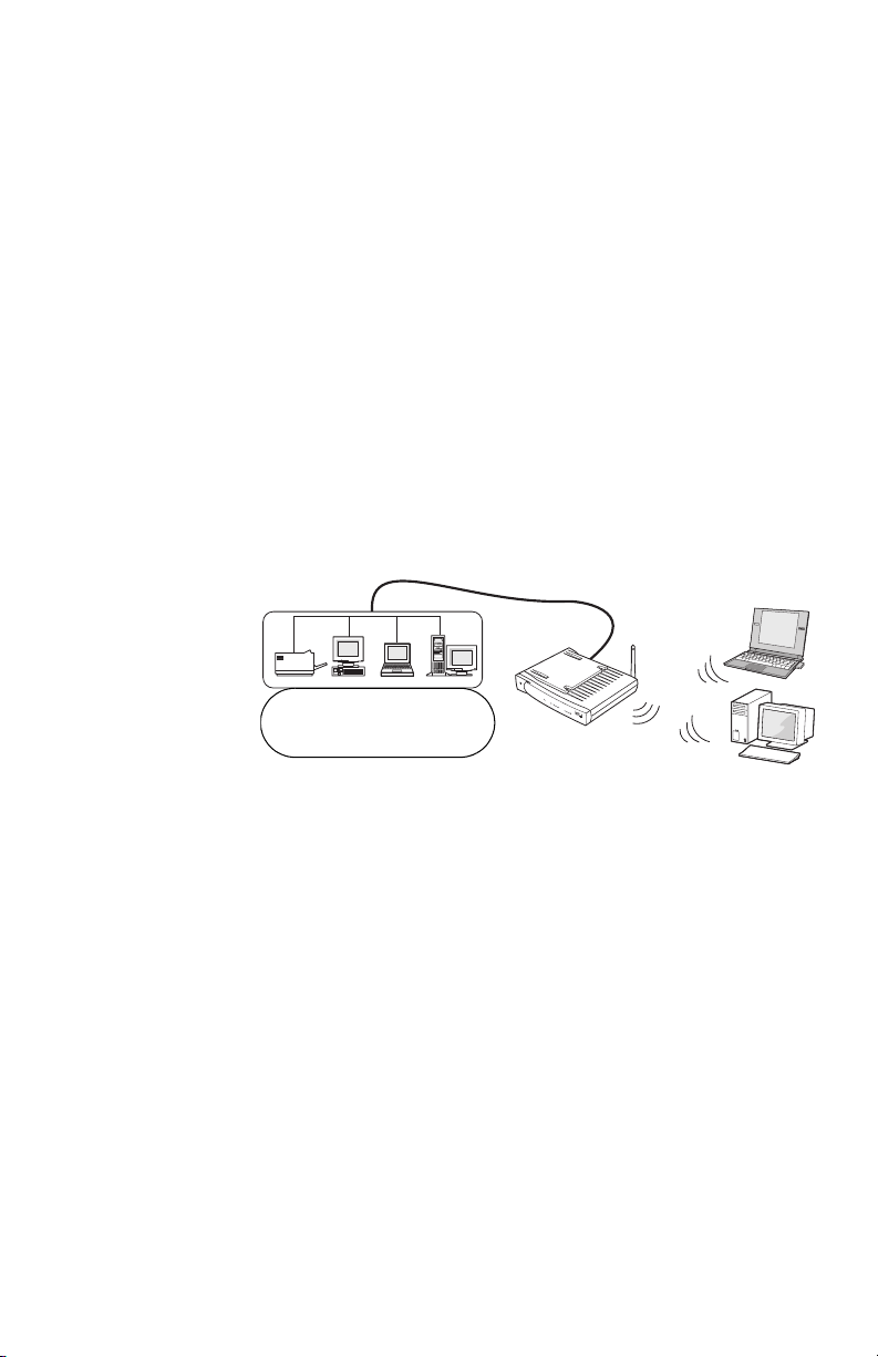
Overview of an
existing
network
If your home or small business network already provides
Internet access and you just want to add wireless
capability to your existing Ethernet network (LAN), you
can configure the gateway as an access point. In this
configuration, the gateway connects wireless PCs to the
wired network. The Internet is accessed through the
wired network (if applicable).
The following diagram shows how such a network might
look.
P
o
w
e
r
Sy
Link
s
t
e
m
In
Acti
t
er
v
n
i
e
t
y
t
1
W
i
rel
es
s
2
3
4
E
t
h
e
rn
e
Existing Ethernet network
with Internet access
t
W
i
re
l
es
s
Ga
t
ew
a
y
II
In the above scenario, the gateway is connected to a hub
or switch through one of the Ethernet ports on the back of
the gateway. The Internet port is not used.
More than four PCs with Ethernet adapters require a hub
or switch and the appropriate cables, for up to 16 wired
PCs.
See Setting Up the Gateway on a Network on page 13 to
begin setting up the gateway on an existing network.
Features of the Intel Wireless Gateway II
Using the gateway, you can share Internet access
seamlessly among all the computers on your network
whether you are using Ethernet or 802.11b Wireless
3
Page 8

Chapter 1 – Overview
(Wi-Fi*) adapters or a combination of any of these
technologies.
The Intel Wireless Gateway II has many benefits:
• Internet sharing. Up to 16 wireless plus 4 wired
connections. More than 4 wired connections requires
a network hub or switch which supports up to 32
connections. (16 wired and 16 wireless connections)
• Firewall and data security. Includes NAT firewall
and 64-bit or 128-bit WEP data encryption.
• Fast. Up to 11 Mbps 802.11b wireless (Wi-Fi*) or 10/
100 Mbps Ethernet communication speed.
• Extensibility. Can easily extend a wired network
with wireless devices to create a seamless network.
• Range. The wireless communication range is up to
300 feet, depending on environmental conditions.
• Easy-to-use. You can set up the gateway easily with
the configuration software.
See Glossary on page 76 for definitions of terms you are
not familiar with.
Verify system and service requirements
The computer you use to configure the gateway must
meet certain requirements.
System
requirements
• Microsoft Windows* 98, Me, 2000 (Professional
version), or XP (Professional or Home version)
• CD-ROM drive
• 800 x 600 resolution monitor (SVGA) or higher
• 10/100 Ethernet adapter
• Web browser (Microsoft Internet Explorer* 5.0 or
later, Netscape Navigator* 4.78 or later, or
equivalent)
4
Page 9

Chapter 1 – Overview
Non-Windows clients can access the Internet through the
Intel Wireless Gateway II, but not configure the gateway.
These PCs must meet the following system
requirements:
• Macintosh* OS 9.2 or later, with Internet Explorer 5.x
or higher
• Linux* system, with Netscape 4.75 or higher
All PCs and laptops connected to the gateway must
have:
• For a wireless connection: a Wi-Fi* approved IEEE
802.11b-compatible adapter (we recommend the
AnyPoint
network adapters).
• For a wired network: IEEE 802.3 10/100 Ethernet
network adapter, or a hub or switch.
®
Wireless II or Intel PRO/Wireless LAN
Service
requirements
To use the Intel Wireless Gateway II to manage your
broadband Internet access, you need:
• An Internet access account from your local telephone
company or an Internet Service Provider (ISP).
• A broadband modem (cable or DSL) with an Ethernet
connection.
A look at the gateway hardware
Front panel The front panel of the Intel Wireless Gateway II has a
series of nine lights that provide information about the
5
Page 10

Chapter 1 – Overview
gateway's operational status. The lights are described
below, from left to right.
4
Wireless Gateway II
LED
Power
Description
Link Activity
Wireless
InternetSystem
123
Ethernet
Power On – The power cable is connected; the gateway has power.
Off – Check that the power cable connectors are securely in
place and plugged into a power source.
System On – This means the gateway is operating.
Off – If this LED is not on, push the Reset buttononthe
back.
Blinking – The Status light blinks whenever any of these reset
situations occur:
• YoupushtheReset button on the gateway’s back panel.
(Refer to Reset in the next table.)
• You click Reset on the System Tools screen in the
gateway configuration software.
Internet On – If you have a broadband modem attached to the
gateway’s Internet port, the light blinks periodically. It blinks at
a rate that corresponds to the amount of Internet traffic (slow
with little traffic and increasingly faster as Internet traffic
increases).
Off – No Internet connection detected.
Wireless Link Off – There are no wireless devices communicating with the
gateway.
Green solid – At least one wireless device is connected to the
gateway.
6
Page 11

Chapter 1 – Overview
LED
Wireless Activity Green blinking – Traffic is detected between at least one
Ethernet 1-4 Off – No PC is connected to the Ethernet port.
Description
wireless device and the gateway.
The Wireless Activity light blinks continually because the
gateway is always checking whether other wireless devices
are trying to connect to it. The more activity that occurs
between wireless PCs and the gateway, the faster this
indicator blinks.
Green solid – A valid link has been established at 10 Mbps.
Green blinking – Traffic is being passed at 10 Mbps.
Amber solid – A valid link has been established at 100 Mbps.
Amber blinking – Traffic is being passed at 100 Mbps.
7
Page 12

Chapter 1 – Overview
Back panel
connectors
Connector
The gateway's back panel includes the cable connectors
and Reset button.
Lock
Reset
4
Internet Ethernet Power
Description
2
3
1
5V/2A
Reset Use an object, such as an open paper clip, to press the reset
switch. You can use the reset switch to either:
• Reset the gateway without losing its current setup values.
Press, then immediately release the reset switch.
• Reset the gateway to its factory-default values. Press and
hold the reset switch for at least 5 seconds before
releasing it.
When the reset operation is complete, the Status light on the
front panel blinks and then stops. See Resetting the gateway
on page 73.
Lock Hardware locking feature. Accepts Kensington-type locking
devices for anti-theft purposes.
Internet Accepts an RJ-45 Ethernet-style connector for attaching the
gateway to your broadband modem.
Ethernet Accepts RJ-45 Ethernet-style connectors for connecting up to
four PCs to the gateway’s 4-port switch.
Power Accepts the cylinder end of the supplied power cable. Plug the
other end of the power cable into a standard electrical outlet.
(We recommend using a surge protector.) See the Power light
on the front panel in the previous table.
Important: Use the power supply included with the Intel
Wireless Gateway II.
8
Page 13

Chapter 1 – Overview
Configuration software and settings
The gateway has internal settings that control the
wireless local area network (WLAN). The gateway also
has settings to control the broadband modem, called ISP
settings. It is important to correctly enter these settings.
Accessing the configuration software
To enter WLAN or ISP settings for the gateway, use the
gateway configuration software. This software is in readonly memory (ROM) inside the gateway.
Step-by-step 1 Click Start > Programs > Intel AnyPoint > Intel
Wireless Gateway II 1210 > Network Setup Utility.
2 When prompted to change the gateway settings, click
Yes.
or
• Open a browser (either Microsoft Internet Explorer*
or Netscape Navigator*) and type the gateway’sIP
address, 192.168.0.10 (unless you changed the
default gateway IP address).
Wireless
settings
If you have not filled out the Install Information
Worksheet, do so now. The worksheet helps you gather
and record wireless and ISP settings that you need to
configure the gateway.
Following are brief descriptions of both types of settings
and how they are used.
Wireless settings determine which wireless devices can
communicate with the gateway. The wireless settings on
the PC's adapter must match the gateway's wireless
settings before the two devices can communicate.
9
Page 14

Chapter 1 – Overview
The settings you must use are the following:
• Network Name (SSID)
•EncryptionKey
You rarely need to change these settings. You can use
the default values.
• Transfer rate: Automatic
• Channel: 11
• Header Length: Long (preamble)
Network Name
(SSID)
Encryption Encryption provides additional data security by
The Network Name (also called SSID) determines which
devices can communicate on your wireless network. To
be on the same network, all devices must have the same
Network Name. When a PC tries to join a wireless
network, it sends its Network Name to the Intel Wireless
Gateway. If the Network Names on both devices match,
the PC is permitted to join. The Network Name is also
called network ID code, SSID (service set identifier), or
ESSID (extended service set identifier).
The gateway has a default Network Name of
“Intel Gateway.” The network name is case sensitive. For
security purposes, we highly recommend you change the
default name. If you have an existing wireless device, you
can give the gateway the same Network Name as your
existing wireless devices, or you can create a new
Network Name and use it on all of your wireless devices.
See Changing Network Name (SSID) on page 26.
converting all of the information that is transmitted over a
wireless network into a form that can be read only by
devices that have the same encryption key. Before
sending information, the device encodes the information
using the key. The receiving device uses the same key to
decode the information. To be on the same network, all
devices must have the same encryption key.
10
Page 15

Chapter 1 – Overview
There are two ways to set encryption:
• Generate a key from text. Enter the same text key
you used on your existing wireless devices, or create
a new one and use it on all of your wireless devices.
The text you use can be any character but it must be
exactly 5 characters or 13 characters long. Five
characters provides 40(64)-bit encryption, while the
13 character string provides 104(128)-bit encryption.
The software automatically generates a hexadecimal
encryption key from the text you enter. To see the
key that was generated, go to the Status screen and
click Details. See Generate an encryption key from
text on page 28.
• Enter a key manually. If the network you are
connecting the gateway to was configured by
manually entering a hexadecimal key (also called a
WEP key), you must use this option. See Manually
enter encryption keys on page 29.
Using data encryption may slightly affect wireless
performance. You can choose an encryption security
level of either 40(64)-bit or 104(128)-bit.
ISP settings If you have already installed a modem, you should be
familiar with these settings. ISP settings control your
Internet connection between the gateway and your
modem. If your modem requires any settings to be made,
your ISP has provided them. For more information about
the ISP settings, refer to the online Help or the Install
Information Worksheet.
11
Page 16

Chapter 1 – Overview
Where to find more information
For more information, go to the following sources for
help.
• See Troubleshooting on page 55.
• Use the troubleshooting online Help, available on the
gateway’s status screen.
12
Page 17

Chapter 2
Setting Up the Gateway on a Network
Note This chapter explains how to set up your Intel
Wireless Gateway II as a wireless access point on an
existing network.
To set up the gateway for a new network, see the
printed Installation Guide, or look for the Installation
Guide PDF file on the CD. Double-click My Computer
> CD-ROM drive > DOCS > English > Gateway >
1210 > install_guide_gw1210.pdf.
Do not attempt to connect multiple computers to form a
network until you have configured the gateway to work
with a single computer, as described in the Installation
Guide.
In this chapter, you’ll find information on the following:
■ Planning your network
■ Connecting the gateway to an Ethernet hub or switch
■ Configuring the gateway as an access point
■ Installing wireless adapters on other PCs
■ Using Windows* XP Client Configuration Manager
■ Configuring the adapter
A word about
networks
This manual assumes that you are familiar with common
network terms and concepts and that you understand
how a basic network is set up. This manual is not meant
to be a comprehensive explanation of networking.
13
Page 18
Chapter 2 – Setting Up the Gateway on a Network
Planning your network
Take some time to plan your network before you begin
installation. If you are setting up a new network with
several network devices, it’s important that you start with
the correct device.
1 Start with the Intel Wireless Gateway II
• To set up the gateway with a new network, see
the Installation Guide.
• To set up the gateway with an existing Ethernet
network, see Connecting the gateway to an
Ethernet hub or switch.
2 Then install wireless network devices such as Intel
AnyPoint
®
Wireless II Network adapters, Intel PRO/
Wireless adapters or third-party 802.11b (Wi-Fi*)
wireless adapters in each PC you want included on
the network.
Instructions are provided with those devices.
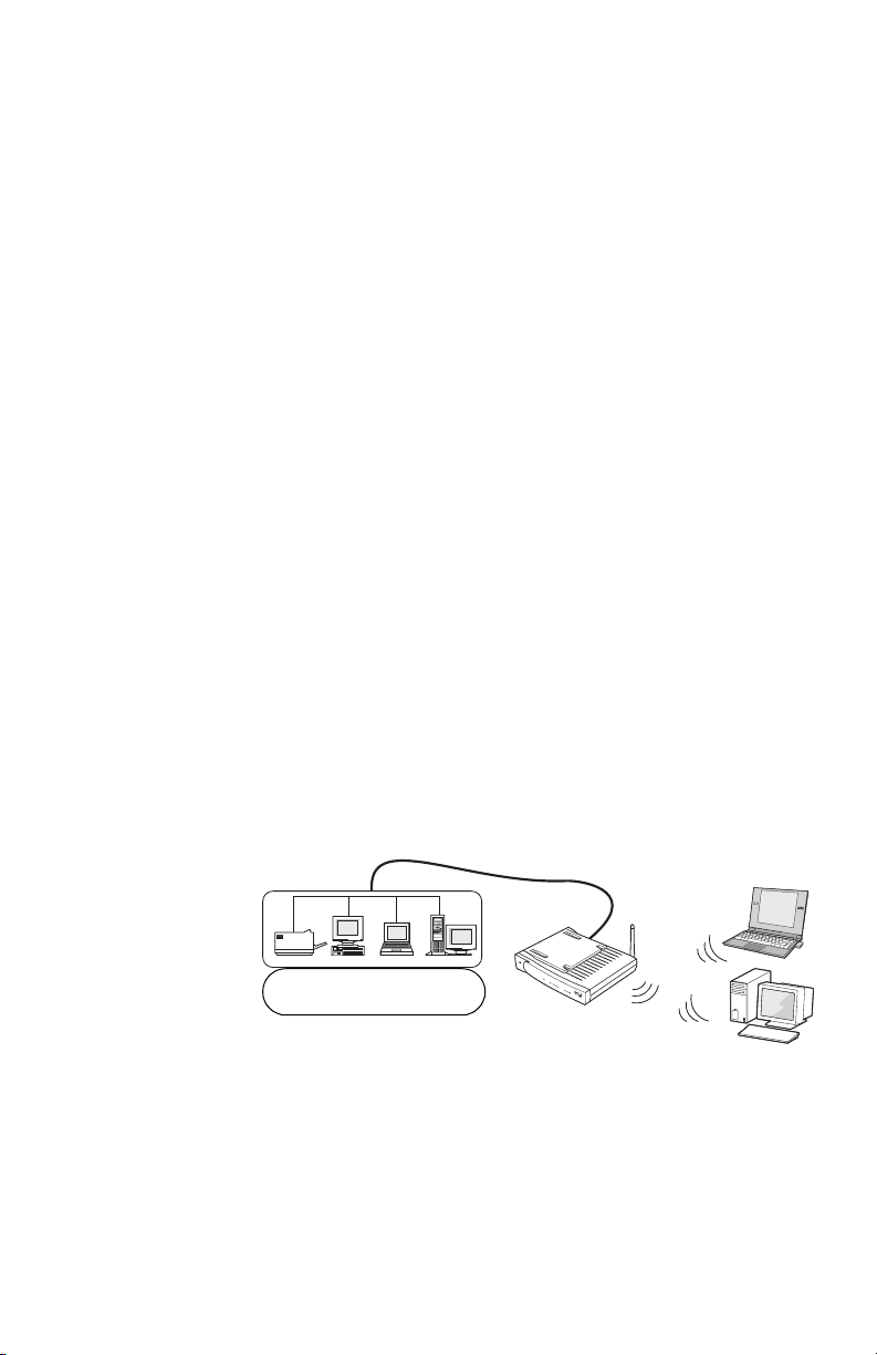
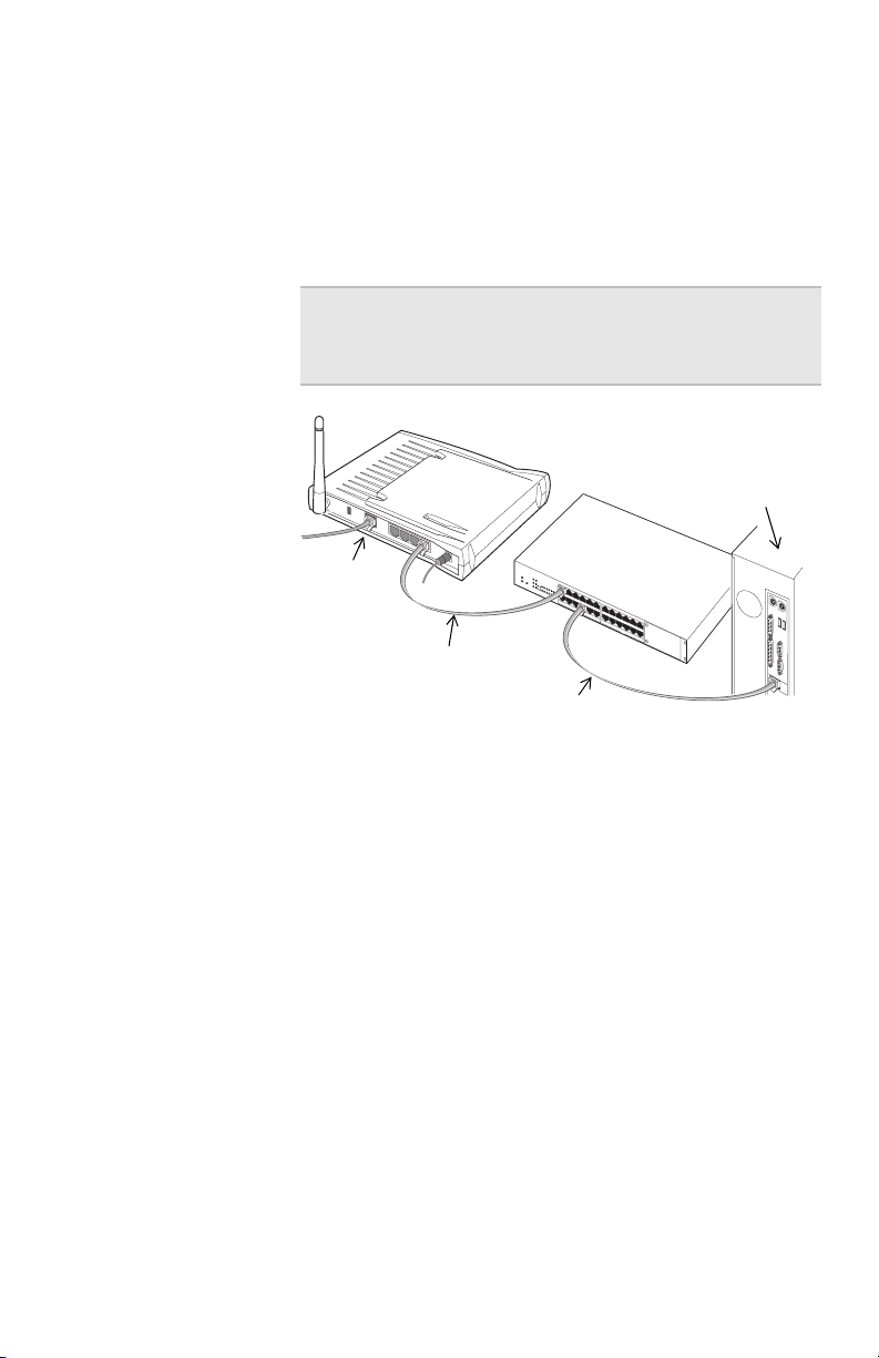
Connecting the gateway to an Ethernet hub or switch
This configuration of the gateway assumes that you
access the Internet through your wired network (not the
gateway).
P
o
w
e
r
Sy
Li
s
n
t
k
e
m
I
n
Acti
t
er
v
n
i
e
ty
t
1
W
i
r
el
es
s
2
Existing Ethernet network
with Internet access
Instructions for connecting your broadband modem
directly to the gateway for Internet access are in the
Installation Guide.
3
4
E
t
h
ern
e
t
W
i
re
l
e
ss
Ga
t
ew
a
y
II
14
Page 19
Chapter 2 – SettingUptheGatewayonaNetwork
Step-by-step These instructions assume you have an existing network
and it is functioning properly.
1 Connect one end of the Ethernet cable (included with
the gateway) to any one of the four Ethernet ports on
the gateway.
Note The other three Ethernet ports on the
gateway can be used for additional network
devices.
R
e
s
e
t
Internet port
I
n
t
er
n
e
t
E
t
n
er
n
e
t
P
o
w
er
To Ethernet port
Hub or switch
Configuration PC
Standard Ethernet cable
2 Connect the other end to the Ethernet cable to an
available port on your hub or switch.
3 Connect the power cable to the power supply.
4 Connect the power cable to an electrical wall outlet.
5 Connect the power supply cable to the Power port on
the gateway.
15
Page 20
Chapter 2 – Setting Up the Gateway on a Network
Configuring the gateway as an access point
Configure the gateway as an access point if you are
adding wireless connectivity to an existing wired
(Ethernet) network.
Note If you are connecting the gateway directly to the
modem that accesses the Internet, follow the
connection instructions in the Installation Guide and
use Gateway Mode.
In this step, you will use the installation CD to configure
your PC-to-gateway connection.
To manually open the gateway configuration software,
open your browser and type 192.168.0.10 in the address
field. The configuration screens are located inside the
gateway, not on the Internet.
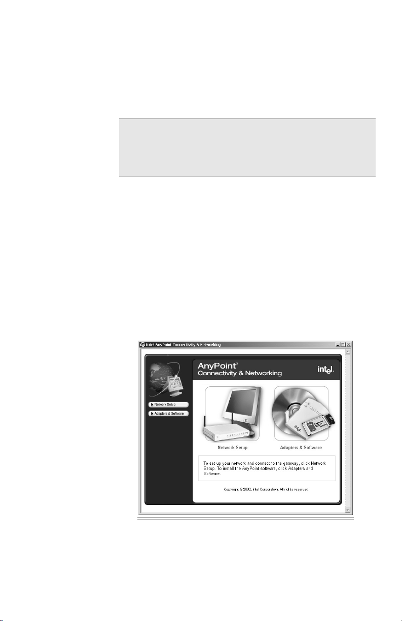
1 Insert the CD and wait for the window to appear.
If the window does not appear, double-click the
program icon for Autorun.exe on the CD.
16
Page 21
Chapter 2 – SettingUptheGatewayonaNetwork
2 Click Network Setup.
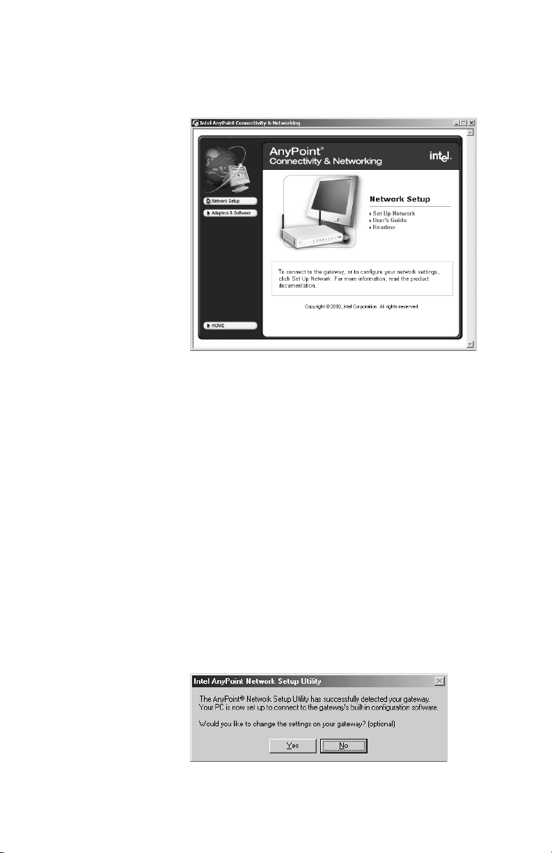
The following appears.
3 Click Set Up Network.
4 You must agree with the conditions of the license
agreement and click I Accept to continue.
The Network Setup screen appears.
5 Click OK to continue.
The Network Setup utility begins looking for the
gateway.
If you receive a message stating the AnyPoint
Network Setup Utility was unable to detect the
gateway, shut down then turn on your PC and start
over with step 1. If that does not work, see
Troubleshooting in the Installation Guide.
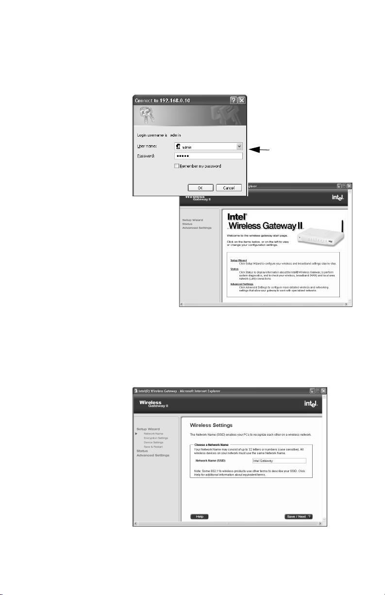
6 When you see the following Network Setup screen,
click Yes.
17
Page 22
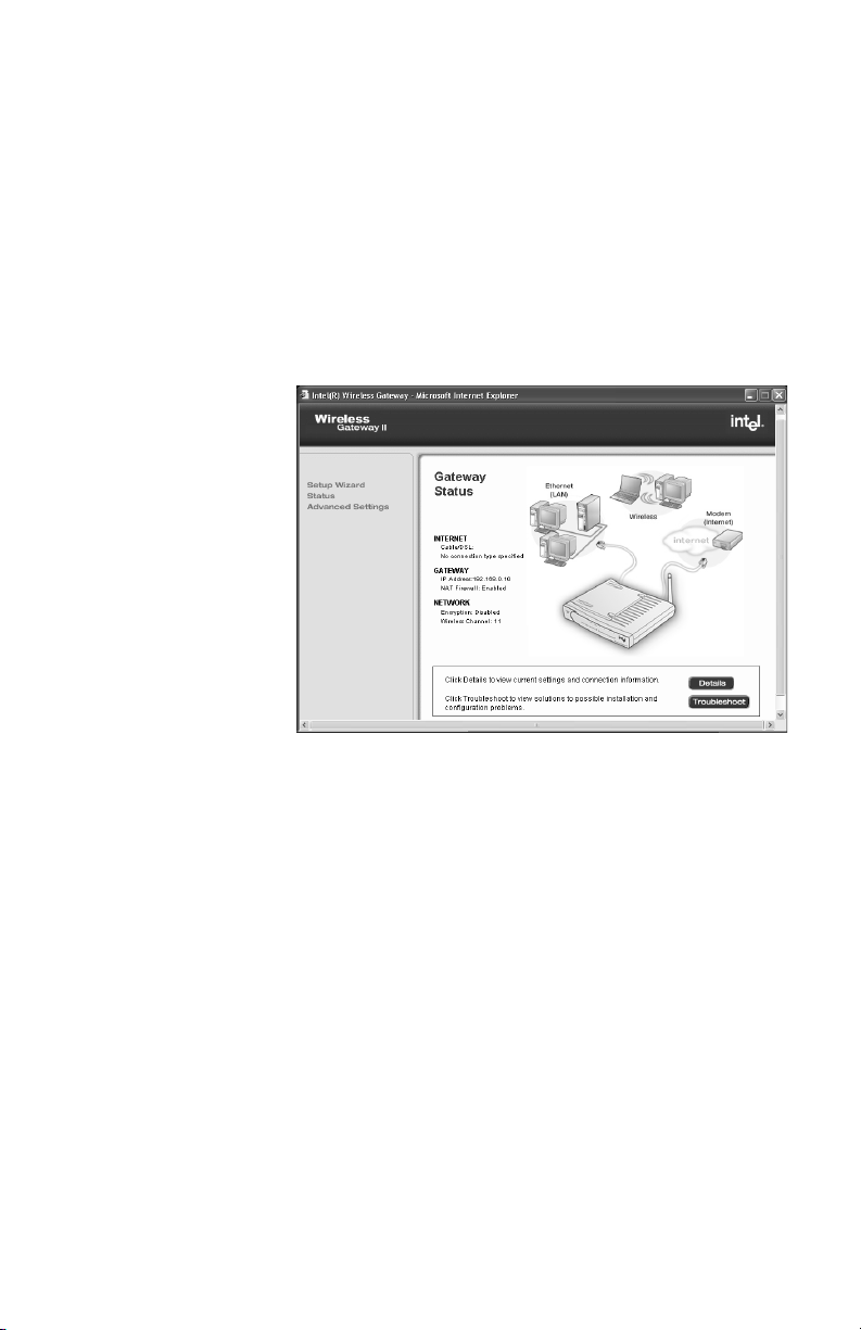
Chapter 2 – Setting Up the Gateway on a Network
7 When prompted, type admin as the user name and
password.
The user name and password are case sensitive.
typeadmininbothfields
(case sensitive)
18
8 When prompted, select the country in which you are
setting up, and then click OK.
9 Click Setup Wizard.
The following appears.
Page 23
Chapter 2 – SettingUptheGatewayonaNetwork
10 On the Wireless Settings screen, create a Network
Name (SSID) to be used by all of your wireless
devices, and then click Save/Next.
For security purposes, we strongly recommend you
change the Network Name from the default name.
Use any letters or numbers up to 32 characters (case
sensitive).
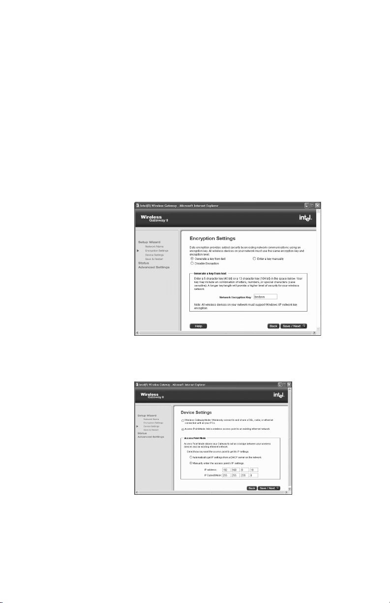
11 On the Encryption Settings screen, type encryption
settings to be used by all of your wireless devices
(recommended for security purposes), and click
Save/Next.
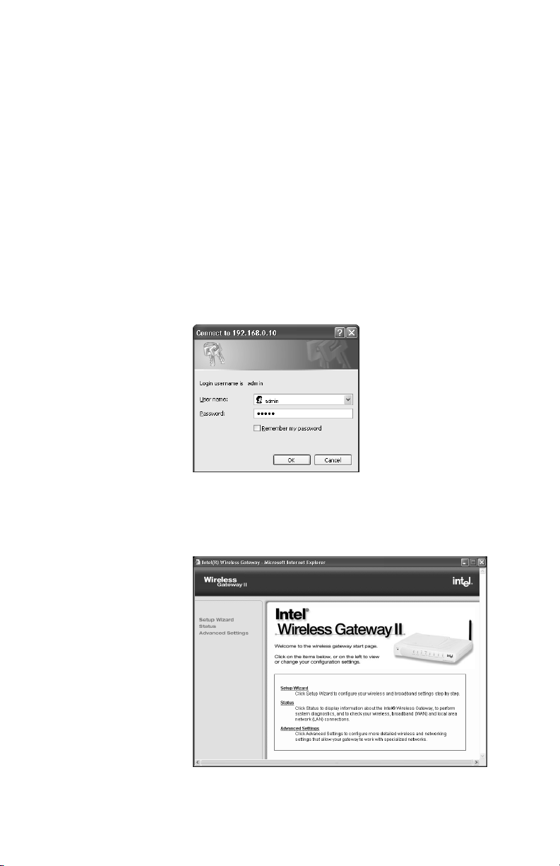
12 On the Device Settings screen, click Access Point
Mode.
19
Page 24

Chapter 2 – Setting Up the Gateway on a Network
13 Choose how you want the gateway to get its IP
address:
• If your wired network has a DHCP server, click
Automatically get IP settings from a DHCP
server on the network.
• If your wired network has IP addresses assigned
to each device (no DHCP server), click Manually
enter the access point’s IP settings. Then
enter a static IP address and subnet mask.
If you enter a static IP address (from your Internet
Service Provider), change the default IP address of the
gateway (192.168.0.10). Be sure to write down the new
address. Use the new address when you access the
configuration software using your browser. If you use the
installation CD-ROM, it automatically detect the new IP
address.
In Access Point mode, the gateway’s DHCP server is
turned off. There can be only one active DHCP server in
your network. You do not enter ISP settings, and the
gateway’s Network Address Translation (NAT) protocol is
disabled. You can enable the gateway to be your DHCP
server by going to the Advanced Settings, DHCP Server
Settings and clicking Enable DHCP Server Functions.
Installing wireless adapters on other PCs
Install other adapters in PCs as described in the user’s
guides that come with those adapters. Configure the
wireless settings on all wireless PCs on the network to
match the gateway’s wireless settings.
20
Page 25

Chapter 2 – SettingUptheGatewayonaNetwork
Step-by-step 1 Refer to your Install Information Worksheet for the
wireless settings you applied to the gateway.
2 Configure the wireless adapter this way:
• Network Name (network ID code or SSID) =
same as you applied to the gateway
• Encryption = same encryption settings as
gateway
• Mode = Infrastructure
3 Verify that you can access the gateway from this PC
by inserting the gateway installation CD and clicking
the Configure the Gateway button.
If you need help doing this, refer to the adapter’s
documentation.
Using Windows* XP Client Configuration Manager
Use the following steps to connect an 802.11b adapter
that uses the Windows XP Client Configuration Manager
to the Intel Wireless Gateway II.
Gateway
settings
If you are using Intel AnyPoint Wireless II network
adapters, and the AnyPoint Connectivity Suite software,
you must use version 2.30.01 or higher of the AnyPoint
Connectivity Suite software to be fully compatible with the
Windows XP Network Key.
If you are using a third-party adapter, follow the
instructions below. Use these instructions from the
status page on the gateway. See Viewing your
connection status on page 16 to help you find the Status
page.
Gather the following gateway settings from the Install
Information Worksheet:
• Encryption level
• Encryption password
21
Page 26

Chapter 2 – Setting Up the Gateway on a Network
• Key number
• Value of the key
Configuring the adapter
Step-by-step 1 On your Windows XP PC, right-click the wireless
adapter icon in the system tray.
2 Choose View available wireless networks.
3 When the Connect to Wireless Network screen
appears, select the access point in the Available
Networks List that displays your Intel Wireless
Gateway. Do not enter a network key at this time.
4 Click Advanced.
YouseeadialogboxshowinganAvailable
Networks list and a Preferred Networks list.
5 From the Available Networks List, select the Gateway
and then click the Configure button.
A Wireless Network Properties screen appears.
22
6 Check Data encryption (WEP enabled). Also, clear
the check box The key is provided for me
automatically.
7 Using the setting from your Install Information
Worksheet, enter the value for the key.
Make sure the key format is in hexadecimal
characters (0-9 and A-F) and the key length is 10
digits (for 40-bit) or 26 digits (for 104-bit).
See Manually enter encryption keys on page 29 for
examples.
8 Click OK.
Clicking OK from the Wireless Network Properties
screen takes you back to the Wireless Network
Connection Properties, where you can click OK again
to exit and save changes.
Page 27

Chapter 3
Changing the Gateway Settings
When you installed your Intel Wireless Gateway II using
the Installation Guide or Chapter 2 – Setting Up the
Gateway on a Network, you were instructed to enter an
address in your Web browser, which launched your Webbased Wireless Gateway Configuration Software.You
used the wizard to enter initial wireless and device
settings for your gateway.
This chapter explains the following:
■ Opening the gateway configuration software
■ Viewing your connection status
■ Changing your wireless settings
■ Changing Network Name (SSID)
■ Changing or disabling your encryption settings
■ Changing your device settings
■ Saving settings and restarting your gateway
23
Page 28
Chapter 3 – Changing the Gateway Settings
Opening the gateway configuration software
The configuration software for the gateway resides inside
the gateway, not on the Internet.
Step-by-step 1 Type the following Internet address into your Web
browser: http://192.168.0.10.
or
Go to Start > Programs > Intel AnyPoint > Intel
Wireless Gateway 1210 > Network Setup, and then
click Yes when asked if you want to change the
gateway settings.
The following appears.
24
2 Enter your user name and password and then click
OK.
The following appears.
Page 29
Chapter 3 – Changing the Gateway Settings
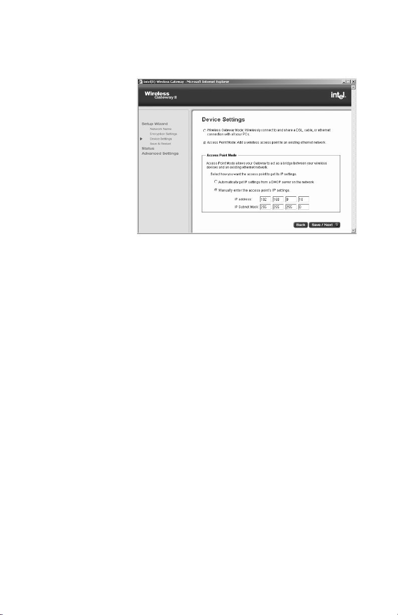
Viewing your connection status
Status provides information about the device
connections (connected, not connected, connection
active) for your broadband modem, your LAN, and your
wireless adapters.
Step-by-step • On the left column of the Wireless Gateway screen,
click Status.
The following appears.
Viewing more status details
To see your current settings (wireless and device
settings), click Details on the Status screen. The
following information appears:
• Wireless
• Local Area Network (LAN)
• Internet Service Provider (ISP)
Printing your gateway settings
Click Print from the Status Details screen to print all your
settings. Save the printed copy, especially if you intend to
change values later.
25
Page 30

Chapter 3 – Changing the Gateway Settingst
Changing your wireless settings
This section describes how to enter wireless settings in
the gateway that match the settings in your wireless
network. If you do not have wireless adapters for your
PCs, you do not need to set the Network Name (SSID) or
the Network encryption settings.
Important! Be sure to enter the same Network Name
(SSID) and network encryption key on each adapter on
your wireless network. If you are a Windows XP user,
see Using Windows* XP Client Configuration Manager
on page 18 for details.
Changing
Network Name
(SSID)
All wireless networks have an assigned Network Name
(SSID) to the wireless network (SSID is sometimes called
ESSID or many other possible naming conventions). As
the network administrator for your network, you can
create (or change) this name. When a computer tries to
join a wireless network, its network adapter sends the
SSID to the Intel Wireless Gateway. If the SSID of the
wireless adapters and the Intel Wireless Gateway are the
same, and the encryption settings match (if any), the
computer is permitted to join.
26
Page 31

Chapter 3 – Changing the Gateway Settings
Step-by-step 1 Open the Wireless Gateway screen, and then click
Setup Wizard.
2 From the Setup Wizard,clickNetwork Name.
The Network Name (SSID) box appears.
If you have already installed your gateway, the
default name appears in the box (Intel Gateway).
3 Enter a new Network Name.
Use any letters or numbers up to 32 characters (case
sensitive).
4 Click Save/Next to apply the change to the gateway.
Click Save/Next until you see the Save & Restart
button to activate and restart your gateway.
27
Page 32

Chapter 3 – Changing the Gateway Settings
Changing or disabling your encryption settings
In a Wireless Local Area Network (WLAN), use
encryption to implement security and protect your
information. Because wireless clients and access points
send and receive information using radio waves, it is
much easier for an unauthorized person to intercept the
information unless you protect the information through
encryption. Network Encryption does not provide
absolute protection for your data, but it does make it
more difficult for someone else to intercept that data. For
conceptual information on encryption, see Encryption on
page 10.
The longer the encryption key is, the stronger the
encryption. The gateway uses either a 40(64)-bit key or a
104(128)-bit key. The 104(128)-bit key has several trillion
times as many possible combinations as a 40(64)-bit key.
For added security, periodically change the value of your
keys.
Important! The gateway and each adapter in the
network must have the same settings for encryption.
Generate an
encryption key
from text
Step-by-step 1 Open the Wireless Gateway screen, and then click
If you have all AnyPoint
XP to configure your adapters, you can create an
encryption key from a 5 or 13 character string. Five
characters provides 40(64)-bit encryption, while the 13
character string provides 104(128)-bit encryption. The
string you enter must be exactly 5 or 13 characters.
Setup Wizard.
2 From the Setup Wizard,clickNetwork Encryption
Settings.
The Network Encryption Settings screen appears.
Read the security warnings.
®
adapters, or are using Windows
28
Page 33

Chapter 3 – Changing the Gateway Settings
3 Select Generate a key from text.
The following appears.
4 Type 5 letters, numbers, or special characters (case
sensitive) in the box.
5 Click Save/Next to apply the change to the gateway.
Click Save/Next until you see the Save & Restart
button to activate and restart your gateway.
Manually enter
encryption
keys
If you have equipment other than AnyPoint network
hardware, you can manually enter a key, either as a
series of hexadecimal digits (characters 0 through 9 and
A through E) or as ASCII characters (any character),
case-sensitive. Encryption keys can be established for
either 40(64)-bit or 104(128)-bit encryption. Longer keys
provide greater security.
A 40(64)-bit key can consist of 10 hexadecimal digits or 5
case-sensitive ASCII characters:
• Example Hex Key: 1AC78 24DE5
• Example ASCII Key: Intel
29
Page 34

Chapter 3 – Changing the Gateway Settings
A 104(128)-bit key can consist of 26 hexadecimal digits
or 13 case-sensitive ASCII characters:
• Example Hex Key: 10111 2EF14 1510 2453
6543 9991
• Example ASCII Key: IntelWireless
Step-by-step To manually enter a 40(64)-bit ASCII encryption key:
1 Open the Wireless Gateway screen, and then click
Setup Wizard.
2 From the Setup Wizard,clickNetwork Encryption
Settings.
The Network Encryption Settings screen appears.
3 Click Enter a key manually.
Although you can use only one encryption key at a
time, having four sets of keys allows you to quickly
change your encryption if necessary.
4 Select 40(64)-bit encryption level.
5 Select ASCII Characters as the Key Format.
6 Enter any combination of 5 case-sensitive characters
in the box.
7 Click Save/Next to apply the change to the gateway.
In the wizard, click Save/Next until you see the Save
& Restart button to activate and restart your
gateway.
encryption
30
Disable
If you are not worried about security and want to slightly
improve data transmission, you can disable encryption.
Important! Be sure to also disable encryption for
each adapter in your wireless network. Refer to the
documentation for your wireless adapter. If you are a
Windows XP user, see Using Windows* XP Client
Configuration Manager on page 18 for details.
Page 35

Chapter 3 – Changing the Gateway Settings
Step-by-step 1 Open the Wireless Gateway screen, and then click
Setup Wizard.
2 From the Setup Wizard,clickNetwork Encryption
Settings.
3 Click Disable Network Encryption.
4 Click Save/Next to apply the change to the gateway.
In the wizard, click Save/Next until you see the Save &
Restart button to activate and restart your gateway.
31
Page 36

Chapter 3 – Changing the Gateway Settings
Changing your device settings
Change device settings to specify one of two gateway
operating modes.
• Wireless Gateway Mode
– Set the gateway to this
mode if you are connecting the gateway directly to a
broadband modem. See Changing Wireless Gateway
Mode settings on page 33.
• Access Point Mode
– Set the gateway to this mode
if you are connecting the gateway to an existing
network. See Changing the access point setting on
page 35.
Step-by-step 1 From the main Wireless Gateway screen, click
Setup Wizard.
2 In the left column under the Setup Wizard, click
Device Settings.
The following appears.
32
Page 37

Chapter 3 – Changing the Gateway Settings
3 Select the mode you want to use.
Note You will lose your connection if you are not
already connected to a DHCP server.
4 Click Save/Next to apply the change to the gateway.
In the wizard, you need to click Save/Next until you
see the Save & Restart button to activate and restart
your gateway.
Changing
Wireless
Gateway Mode
settings
Step-by-step 1 From the Wireless Gateway Mode screen, click
If your Internet Service Provider has assigned settings to
access the Internet, the following sections help you find
the information you need to connect your gateway.
Cable/DSL Settings.
The following appears.
2 See Changing IP settings on page 34, or see
Changing cable or DSL settings on page 34 for
specific information on changing any setting on the
screen.
33
Page 38

Chapter 3 – Changing the Gateway Settings
You can also obtain this information from your modem
documentation or instructions in the Install Information
Worksheet that came with your gateway.
Changing IP
settings
In the IP Settings portion of the Cable/DSL screen, you
can change the following settings:
• IP address assigned by your ISP
– A unique
numeric address that identifies each computer on a
local network as well as on the Internet.
• IP Subnet Mask
– Resembles an IP address and
helps route Internet traffic to a particular local
network or “subnet.”
• ISP Gateway Address
– The IP address of your
Internet service provider's device that routes data
traffic to the Internet.
• Domain Name Server (DNS) IP Address
– The IP
address of your Internet service provider's computer
with a DNS Server. A DNS Server translates a
human-readable address such as www.intel.com into
a numeric IP address such as 192.168.0.10.
Note Change these settings using the instructions
supplied by your broadband provider.
Changing
cable or DSL
settings
34
In the Additional Cable/DSL Settings
portion of the
Cable/DSL screen, you can change the following
settings:
• Username (PPPoE)
– A user name that applies only
if you have a DSL modem that uses the point-to-point
over Ethernet (PPPoE or PPP) protocol. Type the
user name your ISP provided you.
• Password (PPPoE)
– A password that applies only if
you have a DSL modem that uses the point-to-point
over Ethernet (PPPoE or PPP) protocol. Type the
Page 39

Chapter 3 – Changing the Gateway Settings
password your ISP provided you, then retype it to
verify.
• Host Name
– Applies only if you have a cable
modem. If your ISP requires you to enter a host
name, enter it exactly as it was given to you
• Domain Name
– Applies only if you have a cable
modem. If your ISP requires you to enter a domain
name, enter it exactly as it was given to you.
• WAN Ethernet MAC Address
– The WAN Ethernet
Media Access Control (MAC) address uniquely
identifies every device in the network. If your ISP
requires you to enter a MAC address, enter it exactly
as it was given to you.
Note Do not change these settings unless you are
instructed to do so by your broadband provider.
Changing the
access point
setting
If you are not using the Intel Wireless Gateway to access
the Internet, but you want to extend your wired network
with wireless capability, choose the Access Point Mode.
This mode allows you to bridge your wireless PCs to your
Ethernet.
Step-by-step 1 From the main Wireless Gateway screen, click
Setup Wizard.
2 In the left column under the Setup Wizard,click
Device Settings.
35
Page 40
Chapter 3 – Changing the Gateway Settings
3 Click Access Point Mode.
The following appears.
4 Obtain your IP settings:
• Automatically: Click Automatically get IP
settings from a DHCP server on the network
• Manually: Click Manually enter the access
point’s IP settings
36
If you are not connected to a DHCP server when you
change to Access Point Mode, you can lose your
connection. If you do not have a DHCP server, you
may need to specify an IP address. See Refining
DHCP server addressing on page 45.
The IP Address is a unique numeric address that
identifies each computer on a local network as well
as the Internet. The IP Subnet Mask resembles an
IP address and helps route Internet traffic to a
particular local network or “subnet.” You can get
these values from your Install Information Worksheet.
5 Click Save/Next to apply the change to the gateway.
In the wizard, you need to click Save/Next until you
see the Save & Restart button to activate and restart
your gateway.
Page 41

Chapter 3 – Changing the Gateway Settings
Saving settings and restarting your gateway
It’s a good idea to print your new settings and keep them
handy for reference. For details, see Printing your
gateway settings on page 25.
Each time you click Save/Next after making a change in
any of the Setup Wizard screens, the change is instantly
applied to the gateway firmware in Read Only Memory
(ROM). But when you click Save & Restart, your gateway
mode (Gateway Mode or Access Point Mode) hardware
is restarted and all changed values in ROM are
transmitted to the network. Only then is your gateway
fully operational.
Step-by-step 1 From your main Wireless Gateway screen, click
Setup Wizard.
2 In the left column under the Setup Wizard, click Save
& Restart.
The following appears.
3 Click Apply.
You’ll see a message telling you that your system is
resetting. After the gateway sends the values to the
network, you see the main Wireless Settings screen,
and your new settings are applied.
37
Page 42

Chapter 3 – Changing the Gateway Settings
38
Page 43

Chapter 4
Using the Advanced Feature Set
This chapter describes the advanced feature set of the
Intel Wireless Gateway II. It provides instructions for
changing the following advanced settings:
■ Changing your gateway password
■ Changing your advanced wireless settings
■ Using system tools
■ Establishing routing protocols
■ Refining DHCP server addressing
■ Assigning virtual server settings
■ Using access control features
■ Changing your gateway IP address
■ Universal Plug and Play
Not all users should use the advanced features. It is
advisable to use some features only if you have system
administrator experience.
39
Page 44

Chapter 4 – Using the Advanced Feature Set
Accessing advanced features
Step-by-step 1 From the main Wireless Gateway screen, click
Advanced Settings.
The first advanced feature, Change the Gateway
password, appears.
2 From the left navigation column, select the advanced
setting you want to change.
Unlike the Setup Wizard, as soon as you click Apply
in the Advanced Settings screens, the changed value
is immediately saved and stored in the gateway. You
do not need to click Save and Restart.
Changing your gateway password
To prevent network users from gaining access and
changing settings, the gateway is password protected.
Step-by-step 1 From the main Wireless Gateway screen, click
Advanced Settings.
2 From the Advanced Settings screen, click Change
Password.
The following appears.
40
3 Type your new password, then retype it to verify.
Page 45

Chapter 4 – Using the Advanced Feature Set
4 Click Apply.
The password is immediately saved and stored in the
configuration software. Write down your password
and store it in a safe place.
Changing your advanced wireless settings
Note Do not change default values unless you are
experiencing problems.
Use the Advanced Settings screen to quickly change
your wireless settings. The settings include:
• Network Name (SSID)
• Transfer Rate
• Header Length (Preamble)
• Channel
You can change any or all values, then click Apply to
save the new settings.
Step-by-step 1 From the main Wireless Gateway screen, click
Advanced Settings.
The following appears.
41
Page 46

Chapter 4 – Using the Advanced Feature Set
2 Type the Network Name (SSID).
3 Make sure all the wireless adapters for your PCs
have the same SSID.
4 Use the menus to select the correct Transfer Rate,
Header Length (preamble) and operating Channel.
5 Click Apply.
The values are saved and stored in the configuration
software.
Setting your transfer rate
Ignore this setting unless all your devices have an option
to set a short header length.
• Select auto to automatically select the best transfer
rate (recommended).
Setting your operating channel
When selecting your channel:
• Ensure each wireless adapter in the network can
• Only switch channels when interference is preventing
Using system tools
The System Tools screen provides tools for
troubleshooting. See Using the system tools on your
gateway on page 71.
• Upgrade your configuration software
42
operate on the same channel.
a good connection. You might first try channels 1, 6,
and 11 (since these channels do not overlap).
– You can
periodically check the Web to see if there are any
new upgrades to the configuration software. Once
Page 47

you’ve downloaded the file to your computer, click
Browse to find and install the upgrade.
• Reset your gateway
restart your gateway using the current settings.
• Load default settings
your gateway restores the factory settings and
returns you to the initial Wireless Gateway screen.
Establishing routing protocols
Changing your routing protocols is only applicable when
you are connecting your gateway to an existing network
that already uses routing protocols. It may be necessary
to route protocols if you have more than one gateway in
your system. Your gateway allows two types of routing
protocols: Dynamic and Static. With Dynamic routing,
your gateway uses an internal algorithm to automatically
adjust the best routing protocol to other gateways (if there
are any) in your network. With Static routing, you can set
an explicit route when you set the destination IP address,
subnet mask, and gateway IP address.
Chapter 4 – Using the Advanced Feature Set
– When you click Reset,you
– When you click default,
43
Page 48

Chapter 4 – Using the Advanced Feature Set
Dynamic
routing
1 From the main Wireless Gateway screen, click
Advanced Settings.
2 In the left column under Advanced Settings, click
Routing Information.
The following appears.
3 In the SEND field, select the same protocol you use
to transmit data to the network.
4 In the RECEIVE field, select the same protocol you
use to receive data from the network.
5 Click Apply.
The values are saved and stored in the configuration
software.
Static routing 1 From the main Wireless Gateway screen, click
Advanced Settings.
2 In the left column under Advanced Settings, click
Routing Information.
44
Page 49

Chapter 4 – Using the Advanced Feature Set
3 When the Static Routing Table fields appear, type in
the values for:
• Destination IP Address: The address of the
remote network or host.
• Subnet Mask: Assigns the portions of the IP
address that are assigned for the network and
the host.
• Gateway IP Address: The IP address of the
gateway.
4 Click Add to send the values to the Static Routing
Table.
5 Click Apply to save your changes in the gateway.
Refining DHCP server addressing
Note DHCP is automatically disabled when your
gateway is set in Access Point Mode.
The Dynamic Host Configuration Protocol (DHCP) server
can select and configure TCP/IP settings automatically
for every computer in your network. The DHCP Server
Settings screen lets you enable or disable DHCP
services. If you enable the server, you can use the
default IP address range that the server selects, or select
a specified range. You can also select a specific address
for specialized servers in your network, such as for email, the Web, and FTP (as long as the addresses are in
an acceptable range).
45
Page 50

Chapter 4 – Using the Advanced Feature Set
Step-by-step 1 From the main Wireless Gateway screen, click
Advanced Settings.
2 In the left column under Advanced settings, click
DHCP Server Settings.
The following appears.
3 Select Enable DHCP Server Functions if you want
to enable the DHCP server. Otherwise, clear this
check box and click Apply.
4 If you enabled the server, review the default settings
(if any). Type any new IP addresses in the reserved
boxes for local network facilities such as e-mail, the
Web, or an FTP server.
5 Click Apply.
Your changes are sent to the other adapters in the
network immediately.
Assigning virtual server settings
The Virtual Server settings (sometimes called port
mapping) allow you to specify virtual addresses for
special services such as telnet, HTTP, FTP, IRC, SMTP,
POP3, and others.
Your Intel Wireless Gateway II has an integrated Network
Address Translation (NAT) firewall that prevents any
46
Page 51

Chapter 4 – Using the Advanced Feature Set
unrequested data from entering your network. Most
applications (like Web browsing or e-mail) are unaffected
by the NAT firewall because the information that is
returned has been requested by a PC on your network.
However, some applications (such as games and Internet
messaging) experience problems because the NAT
firewall blocks data that is needed for them to function
correctly.
The settings listed on the Virtual Server menu correct the
problems experienced by some applications by allowing
unrequested data to pass through commonly used
services to the PC with the IP Address that was entered.
In addition, you can select All (DMZ) to allow
unrequested data to pass through all parts of your NAT
Firewall to that PC. This disables the NAT firewall for that
PC and should only be done if you experience connection
problems, or if you have additional firewall software
installedonthatPC.
Note If you add a third-party firewall to a PC, you may
be required to configure it to allow internal network
communication. Refer to the third-party documentation
for assistance.
47
Page 52

Chapter 4 – Using the Advanced Feature Set
Step-by-step 1 From the main Wireless Gateway screen, click
Advanced Settings.
2 In the left column under Advanced Settings, click
Virtual Server Settings.
The following appears.
3 Select a service, then type the address for that
service.
4 Click Apply to save the addresses in the gateway.
Custom Virtual
Server
Settings
48
Port forwarding is useful if you have a Web server
running on a computer on your local network. It allows
you to direct traffic to a specific computer on your
network automatically.
You may also need port forwarding to host some multiplayer games, for video phone applications, and for other
interactive applications.
Port forwarding only applies to unsolicited inbound traffic.
If you enter an address to access a Web page on the
Internet, the Web page is displayed on your browser.
This is known as solicited traffic.
Page 53

Chapter 4 – Using the Advanced Feature Set
If you don’t use port forwarding, then all unsolicited
inbound traffic is blocked by the gateway’s internal
firewall.
Depending on the application or game that requires port
forwarding, you may find configuration information in its
documentation or on the Web.
You can create a custom rule that defines a specific port
and protocol for unsolicited inbound traffic.
To create a
custom rule
1 From the main Wireless Gateway screen, click
Advanced Settings.
2 In the left column under Advanced Settings, click
Virtual Server Settings.
3 Under Custom Settings, type an address, and then
click Custom Settings.
4 Enter a port number or range of ports in the Firewall
Port field.
5 Select a transport layer protocol from the Protocol
list.
6 For increased security purposes, optionally enter a
Source IP Address as one of the criteria for the port
forward packet to satisfy. You must also specify a
Source IP Address to forward certain transport layer
protocols like ICMP, GRE, and so on from a client on
the Internet to one of the local clients. (If you select
such a transport protocol and do not specify a Source
IP Address, you will be prompted to do so when you
click Apply.)
Ports can be forwarded individually or as a range
separated by a dash (for example, 23 or 24-1023).
The port numbers can be entered in the table in any
order.
A range may be specified and then individual numbers
within that range may be directed to a different IP
address. For example, you may enter a range of 1-1024
49
Page 54
Chapter 4 – Using the Advanced Feature Set
in the Port field and an IP address of 192.168.0.251. You
can then designate Ports 23, 80, and 53 to IP address
192.168.0.252. Traffic destined for Ports 23, 80, and 53
only go to IP address 192.168.0.252.
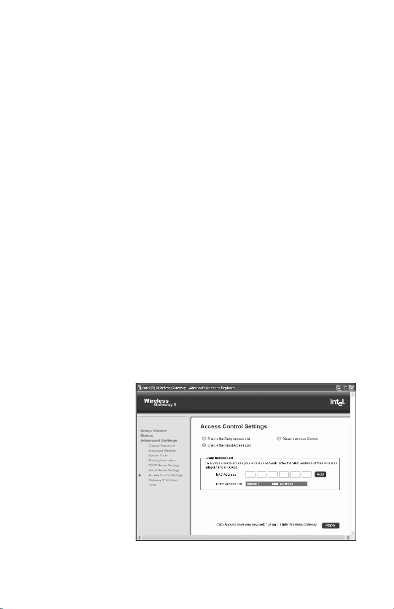
Using access control features
Using access control provides additional security beyond
encryption. You can create a list of users that are granted
access to your network based on their device ID, the
Media Access Control (MAC) address. With access
control, you can also create a list of users that are denied
access. In normal operation, the access control features
are disabled.
Step-by-step 1 From the main Wireless Gateway screen, click
Advanced Settings.
2 In the left column under Advanced Settings, click
Access Control.
3 To create a list of users that you want to grant access
to your gateway, click Enable the Grant Access
List.
If you are creating a list of users you want to deny
access to, click the Enable the Deny Access List
.
50
The following screen appears.
Page 55

Chapter 4 – Using the Advanced Feature Set
4 Type two hexadecimal characters in each box of the
MAC address until are boxes are filled.
5 Click Add to add the device MAC address to the list.
If you want to delete addresses from the list, click the
check box beside the specified MAC address and
then click Delete to remove it from the list.
6 Click Apply to save your settings in the gateway.
Changing your gateway IP address
You might need to change your gateway IP address
when setting up the gateway on an existing network.
Note If you change your gateway IP address, you also
need to change the IP addresses of each network
adapter in the same network.
Step-by-step 1 From the main Wireless Gateway screen, click
Advanced Settings.
2 In the left column under Advanced Settings, click
Gateway IP Address.
The following appears.
51
Page 56

Chapter 4 – Using the Advanced Feature Set
3 Type the new gateway address into the address
boxes.
4 Click Apply to save the new address in the gateway.
IP addressing in network adapters
Make sure IP addressing is set correctly on the network
adapter you are using to connect to the Wireless
Gateway. When the Wireless Gateway is installed as
shown in the Installation Guide, your network adapter
must be set to obtain an IP address and a DNS
address automatically (DHCP enabled).
Windows* XP 1 Click Start > Control Panel.
2 Double-click Network Connections.
3 Right-click the network connection and select
Properties.
4 On the scroll down list, double-click Internet
Protocol (TCP/IP).
5 On the General tab, select Obtain an IP address
automatically.
6 Then select Obtain DNS server address
automatically, and click OK.
Windows 2000 1 Click Start > Settings > Control Panel.
2 Double-click Network and Dial-up Connections.
3 Double-click the icon representing your network
adapter and select the Properties button.
4 On the scroll list, double-click Internet Protocol
(TCP/IP).
5 Select Obtain an IP address automatically.
6 On the General tab, select Obtain DNS server
address automatically and click OK.
Windows ME
and 98
1 Click Start > Settings > Control Panel.
2 Double-click Network.
52
Page 57

3 Double-click the TCP/IP protocol associated with
your network adapter.
4 On the IP Address tab, select Obtain an IP address
automatically.
5 On the DNS Configuration tab, select Disable DNS
and click OK.
Universal Plug and Play
Universal Plug and Play (UPnP*) allows supported
operating systems and application software to
automatically configure a connection to the Internet. With
UPnP enabled, the device configures itself for Internet
access when you add the gateway into the network.
You can disable Universal Plug and Play (enabled, by
default).
To learn how to enable Universal Plug and Play in
Windows XP and ME, see I’mtryingtouseUPnP.How
do I enable it? on page 68.
Chapter 4 – Using the Advanced Feature Set
To disable
Universal Plug
and Play on
the gateway
Note Windows* XP and ME editions support UPnP.
Other versions of Windows require a third-party product
to use UPnP.
Universal Plug and Play must be installed and enabled
on all computers on which you want to view and control
devices. This is usually done through the operating
system or configuration software of each device. UPnP
53
Page 58

Chapter 4 – Using the Advanced Feature Set
can be found in newer operating systems (Windows XP
and ME editions), but is not installed by default.
1 From the main Wireless Gateway screen, click
Advanced Settings.
2 In the left column under Advanced Settings, click
UPnP.
The following appears.
54
3 Click Enable Universal Plug and Plan (UPnP) to
remove the check mark.
4 Click Apply to save your settings.
Page 59

Chapter 5
Troubleshooting
Refer to the README and Late Breaking News for
additional troubleshooting issues and information. The
README is on the CD and the Late Breaking News is a
paper insert.
This chapter presents rudimentary troubleshooting
techniques to help you locate operating problems with
your gateway and device connections. It provides the
following troubleshooting assistance:
■ Problems and solutions
■ Reading settings and device status
■ Using firmware troubleshooting tips
■ Using the system tools on your gateway
55
Page 60

Chapter 5 – Troubleshooting
Problems and solutions
The problems and solutions presented in this chapter
assume that you are operating the gateway in wireless
gateway mode.
Problem I can’t connect to the gateway
If you can access the Wireless Configuration Software,
then you are connected to the gateway.
Solution A Wired Network
• Verify that the gateway power is turned ON – the
gateway’s Power LED (far left LED – separate from
the bank of eight LEDs) should be illuminated.
See A look at the gateway hardware on page 5 for a
description of the LEDs and their location.
• Verify that the System LED (far left in the bank of
eight LEDs) is steady green, indicating the gateway
is operating correctly.
• Check your connections – see the diagrams in the
Installation Guide. You may need to replace the
cable associated with the connection if the LED
differs from the description below:
• Verify that the Ethernet LED (one of four LEDs
on the right) is solid or blinking, green or amber
(indicating link at 10 or 100 Mbps)
• Power down your PC, then power it back on. Run the
Network Setup Utility (go to Start > Programs > Intel
AnyPoint > Intel Wireless Gateway 1210 >
Network Setup). If there are errors, follow the
instructions on screen.
• Can you access the Wireless Gateway configuration
software? – From your Web browser, enter the
Internet address, http://192.168.0.10 (this is the
default value – assumes it has not been changed in
the Wireless Gateway configuration software). If the
56
Page 61

Chapter 5 – Troubleshooting
welcome screen does not appear, then make sure
the “IP addressing” on the network adapter to which
the gateway is connected is set as follows:
• The adapter is set to obtain an IP address
automatically.
You can verify the PC adapter is set correctly by
going to an MS-DOS or command prompt. At the
command prompt type:
ipconfig /all
(leave a space before /all)
If information scrolls off the screen, use
| more
(| is shift-1)
• Verify the adapter that is connecting to the
gateway has an IP address range of
192.168.100.X (where X is between 1 and 254)
and the default Gateway address is
192.168.0.10.
If the IP address is not correct, verify cables (or
wireless settings) are correct and securely
attached, remove (or configure a trusted IP range
for) software firewalls you've installed on the PC,
then restart your PC and check the IP address
again.
• In your Web browser, specify to not use a proxy
server when connecting to the Internet (refer to
your browser’s help pages for information).
• The adapter is set to obtain a DNS address
automatically for Windows* 2000 and Windows
XP
• The adapter has DNS disabled for Windows 98,
Windows 98SE, and Windows ME.
57
Page 62

Chapter 5 – Troubleshooting
Solution B Wireless Network
• Follow the above solutions for a wired network
• Verify that there is a wireless client connected – the
gateway’s Wireless Link LED (third from the right in
the bank of eight LEDs) blinks green when it detects
traffic.
• Verify that your wireless adapter is set to operate in
Infrastructure mode and uses the same Network ID
(SSID) code and encryption settings as the gateway.
See Setting or checking your IP address on page 18.
Problem I can’t share files and printers among the PCs on my
network
Solution • Verify that each PC on the network can connect to
the gateway (See I can’t connect to the gateway on
page 56).
• Verify that each PC can “see” every other PC on the
network. For instance, on Windows 2000 you would
click “My Network Places” to locate each PC by its
system name (on Windows 9x, click “Network
Neighborhood”).
• If you add a third-party firewall to a PC, you may be
required to configure it to allow internal network
communication. Refer to the firewall documentation
for assistance.
• Because the operating system network browser can
take up to 15 minutes to refresh using TCP/IP, make
sure that all PCs have the Microsoft IPX/SPX
58
Page 63

Chapter 5 – Troubleshooting
protocol properly installed with “Frame type” set to
802.3 on the protocol’s Advanced tab.
• Also make sure that Client for Microsoft Networking
and File and Print Sharing are properly installed, as
described below:
Note If you are using AnyPoint adapters, this is all
taken care of automatically.
Windows 98 or ME
1 Click Start > Settings > Control Panel > Network.
2 To add file and print sharing, click File and Print
Sharing and then click OK.
3 Follow the onscreen prompts to insert your Windows
CD and allow your PC to copy the necessary files.
4 To add a client such as Client for Microsoft Networks
or a network protocol, click Add.
5 Choose from among the subsequent dialog boxes
according to what you want to add and then click OK.
6 Follow the screen prompts to insert your Windows
CD, and your PC copies the necessary files.
Windows 2000
1 Click Start > Settings > Control Panel > Network
and Dial-up Connections.
2 To add file and print sharing or a client or protocol,
right-click the icon representing the network
connection your changes should apply to.
3 Click Properties.
4 Click the Install button and select either client,
service or protocol according to what you want to
add.
59
Page 64

Chapter 5 – Troubleshooting
5 Choose from among the dialog boxes that follow, and
6 Follow the screen prompts to insert your Windows
Windows XP
1 Click Start > Control Panel > Network
2 To add file and print sharing or a client or protocol,
3 Click Properties.
4 Click the Install button and select either client,
5 Choose from among the dialog boxes that follow,
• Try again to see that each PC can “see” every other
• When other PCs become visible, use standard
then click OK.
CD, and your PC copies the necessary files.
Connections.
right-click the icon representing the network
connection your changes should apply to.
service or protocol according to what you want to
add.
then click OK.
PC on the network. For instance, on Windows 2000
you would click “My Network Places” to locate each
PC by its system name (on Windows 9x, you would
click “Network Neighborhood”).
procedures to share and map drives and printers.
60
Problem I can’t connect to the Internet through my gateway
The assumption for the solution below is that you were
able to connect to the Internet before you inserted the
gateway into your network.
Solution • Verify that each PC on the network can connect to
the gateway (see I can’t connect to the gateway on
page 56).
• Verify that the gateway Internet LED is solid green. If
the Internet light is off, be sure the Ethernet cable is
Page 65

Chapter 5 – Troubleshooting
the proper type for your modem and that it is
connected to the modem.
• Verify all your modem connections are securely
attached.
• Turn off the power to your modem, wait at least 5
seconds, then turn off the power to the gateway. Turn
power back on in the following order:
• Attach power to the broadband modem, and
allow the modem to fully initialize as indicated by
the modem LEDs (see modem documentation).
• Attach power to the gateway. Confirm the
Internet LED is solid or blinking green.
• If the Internet LED on the gateway is off, unplug
power from the gateway, and attach a new cable
between the broadband modem and gateway.
Turn power back on to the gateway, and verify
the Internet LED is solid green.
• Verify that the Cable/DSL Settings in the wireless
gateway configuration software are correct. See
Changing your device settings on page 32.
Problem I can’t connect to the gateway’s configuration Web
page
Solution Check that you have disabled your proxy settings in your
browser (refer to your browser’s help pages for
information).
Make sure your temporary Internet files are deleted.
Refer to the browser documentation for how to do this.
Problem I’ve made changes to the gateway, clicked Save and
Restart, and now can’t connect to the gateway
Solution There are several possible solutions:
• You’ve changed a setting on the gateway, such as
the Gateway IP address, disabled the DHCP server,
61
Page 66

Chapter 5 – Troubleshooting
• Verify you can connect to the gateway from a wired
• See I can’t connect to the gateway on page 56.
Problem I’m experiencing intermittent connections
Solution You are likely experiencing interference from other
wireless devices (such as your microwave oven or
cordless phone).
or changed mode or wireless settings. Restart your
PC and try connecting to the gateway again. If you
still cannot connect to the gateway, reset the
gateway to factory defaults. Locate the reset switch
(next to the antenna on the rear panel). Press the
reset switch, using an open paper clip, for 5 seconds.
connection. If you changed wireless settings, you can
verify the settings you’ve changed from a wired PC.
See Viewing more status details on page 25.
Consult the solution that applies to your network
(wired or wireless network).
62
• Make sure the antenna on the gateway is extended
(and on your USB adapters, if applicable).
• Increase the distance between wireless devices (for
instance, don’t position your gateway or adapters
near your cordless phone’s base).
• If you live in a multi-level dwelling, change the
direction of the antenna on the gateway to point
directly toward you (when facing the rear panel). This
provides better coverage for multi-level buildings.
• Switch to another channel on your cordless phone, if
possible.
• Change the channel on the gateway to channel 1, 6,
or 11 (these channels do not overlap each other).
Page 67

Chapter 5 – Troubleshooting
See Setting your operating channel on page 42 for
more information.
Note If you change the channel on your gateway,
you need to reboot all your wireless connected
PCs.
Problem I’m having trouble connecting to my Internet game
server
Solution Consult your documentation for your game to determine
the correct ports to open for your game to operate
correctly behind a firewall. See Assigning virtual server
settings on page 46.
Problem I’m having trouble getting AOL* working
Solution • Configure the AOL software connection setup for a
TCP/IP (direct) or LAN connection. Save your
settings then try again.
You may not be able to have more than one instance
of the AOL software open at the same time, for a
given account. That is, if you are currently accessing
the Internet on a PC using the AOL software, you
may need to use another browser or another AOL
account to access the Internet on another PC.
• If you still cannot connect, then verify that you can
access the Internet in general through another Web
browser (Netscape, Internet Explorer).
• If you are able to access the Internet, but cannot
access AOL, then refer to your AOL documentation
for help and technical support information.
Problem I’m having trouble getting my e-mail working
Solution • Verify that you have entered the correct Domain
Name (DNS entry) from your Install Information
63
Page 68

Chapter 5 – Troubleshooting
• Verify that each PC connected to the gateway can
• Check the e-mail settings provided by your ISP on
Problem I’m using a third-party adapter and I cannot access
the gateway or the Internet
Solution Use the following instructions to make sure the network
properties are set correctly for obtaining an IP address.
Setting or checking your IP address
Depending on your operating system, follow the
appropriate set of instructions.
Worksheet. If it is correct, you should be able to
browse the Internet.
access the Internet. See I can’t connect to the
Internet through my gateway on page 60.
each PC.
Note If you can access the Internet, the problem is
NOT in the gateway.
64
Windows 98 and ME
1 Click Start > Settings > Control Panel > Network.
2 Select the TCP/IP --> [the name of the Network
Adapter]. For example, Intel
®
AnyPoint®Wireless II
Adapter.
3 Click Properties.
4 Click the IP Address tab.
5 Make sure that the Obtain an IP address
automatically option is selected.
6 On the DNS Configuration tab, make sure Disable
DNS is selected.
7 If one or both are not selected, select them, and then
restart the PC.
Page 69

Chapter 5 – Troubleshooting
Windows 2000
1 Click Start > Settings > Network and Dial-up
Connections.
2 Right-click [the name of the Network Adapter], for
example, Intel AnyPoint Wireless II Adapter, and
select Properties.
3 In the Local Area Connection Properties dialog box,
click Internet Protocol (TCP/IP).
4 Click Properties.
5 Make sure that the Obtain an IP address
automatically option is selected.
6 Make sure that the Obtain DNS server address
automatically option is selected.
7 If one or both are not selected, select them and
restart the PC after you make the change.
Windows XP
1 Click Start > Control Panel > Network
Connections, and then click Network Connections.
2 Right-click [the name of the Network Adapter], for
example, Intel AnyPoint Wireless II Adapter, and
select Properties.
3 In the Local Area Connection Properties dialog box,
click Internet Protocol (TCP/IP).
4 Click Properties.
5 Make sure that the Obtain an IP address
automatically option is selected.
6 Make sure that the Obtain DNS server address
automatically option is selected.
7 If one or both are not selected, select them and
restart the PC after you make the change.
65
Page 70

Chapter 5 – Troubleshooting
Problem I’m using Internet Connection Sharing (ICS) and
don’t know how to remove it
Solution Internet Connection Sharing is a software method for
sharing an Internet connection. The gateway provides
this method now. To manually remove ICS, use the
following instructions for your operating system.
Windows 98
1 Click Start > Settings > Control Panel > Add/
2 Click the Windows Setup tab.
3 Click Internet Tools and then click Details.
4 Select Internet Connection Sharing to remove the
5 Click Apply to save your changes.
Remove Programs.
check mark, and then click OK.
Windows removes the components and prompts you
to restart your PC.
66
6 Click Yes to restart.
Windows ME
1 Click Start > Settings > Control Panel > Add/
Remove Programs.
2 Click the Windows Setup tab, click
Communications, and then click Details.
3 Select Internet Connection Sharing to remove the
check mark, and then click OK.
4 Click OK.
Windows removes the components and prompts you
to restart your PC.
5 Click Yes to restart.
Page 71

Chapter 5 – Troubleshooting
Windows 2000
1 Click Start > Control Panel > Network and Dial-Up
Connections.
2 Right-click the dial-up, VPN, or incoming connection
you have shared, and then click Properties.
3 On the Sharing tab, remove the Enable Internet
connection sharing for this connection check box,
and click OK.
Windows XP
1 Click Start > Control Panel > Network
Connections.
2 Click the connection you have shared, and then
under Network Tasks,clickChange settings of
this connection.
3 On the Advanced tab, remove the Allow other
network users to connect through this
computer’s Internet connection check box, and
click OK.
Problem My Internet game, which is Universal Plug and Play
aware, does not work
Solution Make sure Universal Plug and Play is enabled on the
gateway. See Universal Plug and Play on page 53.
You also may need to enable UPnP on your Windows
system. See the following problem and solution.
Note Windows XP and Me editions support UPnP.
Other versions of Windows will require a third-party
product to use UPnP.
67
Page 72

Chapter 5 – Troubleshooting
Problem I’m trying to use UPnP. How do I enable it?
Solution Instructions for installing UPnP on Windows XP and
Windows ME follows. Other versions of Windows will
require a third-party product to use UPnP.
Windows ME
1 Click Start > Settings > Control Panel > Add/
2 Click the Windows Setup tab.
3 In the Components list, select the Communications
4 Make sure the Universal Plug and Play check box is
5 Click Apply to save your changes.
6 Click Yes to restart.
Remove Programs.
check box, and then click Details.
selected and then click OK.
Windows installs the components. You are prompted
to restart your PC.
68
Windows XP
1 Click Start > Control Panel > Add or Remove
Programs, and then in the left channel, click Add/
Remove Windows Components.
2 In the Components list, select the Networking
Services check box, and then click Details.
3 Select Universal Plug and Play, and then click OK.
4 Click Next and then Finish.
Problem My Internet game does not work
Solution You may need to enable a custom rule on the gateway.
See To create a custom rule on page 49. Also, see I’m
having trouble connecting to my Internet game server on
page 63.
Page 73

Chapter 5 – Troubleshooting
Problem I can’t take my laptop and roam between access
points
Solution The Intel Wireless Gateway II is not specifically designed
to be used in this kind of environment; however, to locate
an access point, your wireless adapter might need to be
reset to find the gateway. To do so,
Go to an MS-DOS or command prompt and type:
ipconfig /renew
If you are using an AnyPoint Wireless II network adapter
and AnyPoint software:
1 Open the AnyPoint Connection Manager and click
the Profile Manager tab.
2 Click Scan.
Your adapter automatically finds the gateway and
displays its Network Name in a dialog box.
3 Select the gateway's Network Name and click
Connect.
4 Verify that you can connect to the Internet by opening
your Web browser and navigating to a familiar Web
site.
If all else fails
If you are using a third-party network adapter, see the
adapter documentation for how to configure the adapter
to connect with an access point.
If none of the previous problems and solutions seem to
match your situation, try the following:
• Turn off the power to your modem, wait at least 5
seconds, then turn it back on.
• Reset the gateway. See Resetting the gateway on
page 73.
69
Page 74

Chapter 5 – Troubleshooting
• If you cannot get to the system tools screen to
perform this reset, then unplug the power cord from
the gateway, wait at least 5 seconds, then plug the
power cord back in.
• Restore the gateway to its original factory defaults.
See Loading default settings on page 73.
Reconfigure the gateway using the gateway configuration
software. See Resetting the gateway on page 73.
Reading the gateway indicator lights
As an initial operational check of your gateway, check the
indicator lights. The indicators are:
• System – Normally on. Blinks during reset or when
applying new gateway configuration information.
• Ethernet – Blinks at a rate that corresponds to the
amount of Ethernet traffic on the Ethernet ports.
• Internet – Blinks at a rate that corresponds to the
amount of Internet traffic on the Internet port.
• Wireless – The Wireless Activity and Link lights blink
at a rate that corresponds to the amount of traffic that
occurs between wireless PCs and the gateway.
These lights always have some activity because the
gateway is constantly attempting to receive data.
• Power – Normally on. If off, check that the power
cable connectors are securely in place.
See A look at the gateway hardware on page 5 for a
description of the LEDs and their location.
Reading settings and device status
If you are having connection problems with your
broadband modem, or the wired or wireless network,
check the Status screen. From this screen, you can see if
your connections are active or not connected. You can
70
Page 75
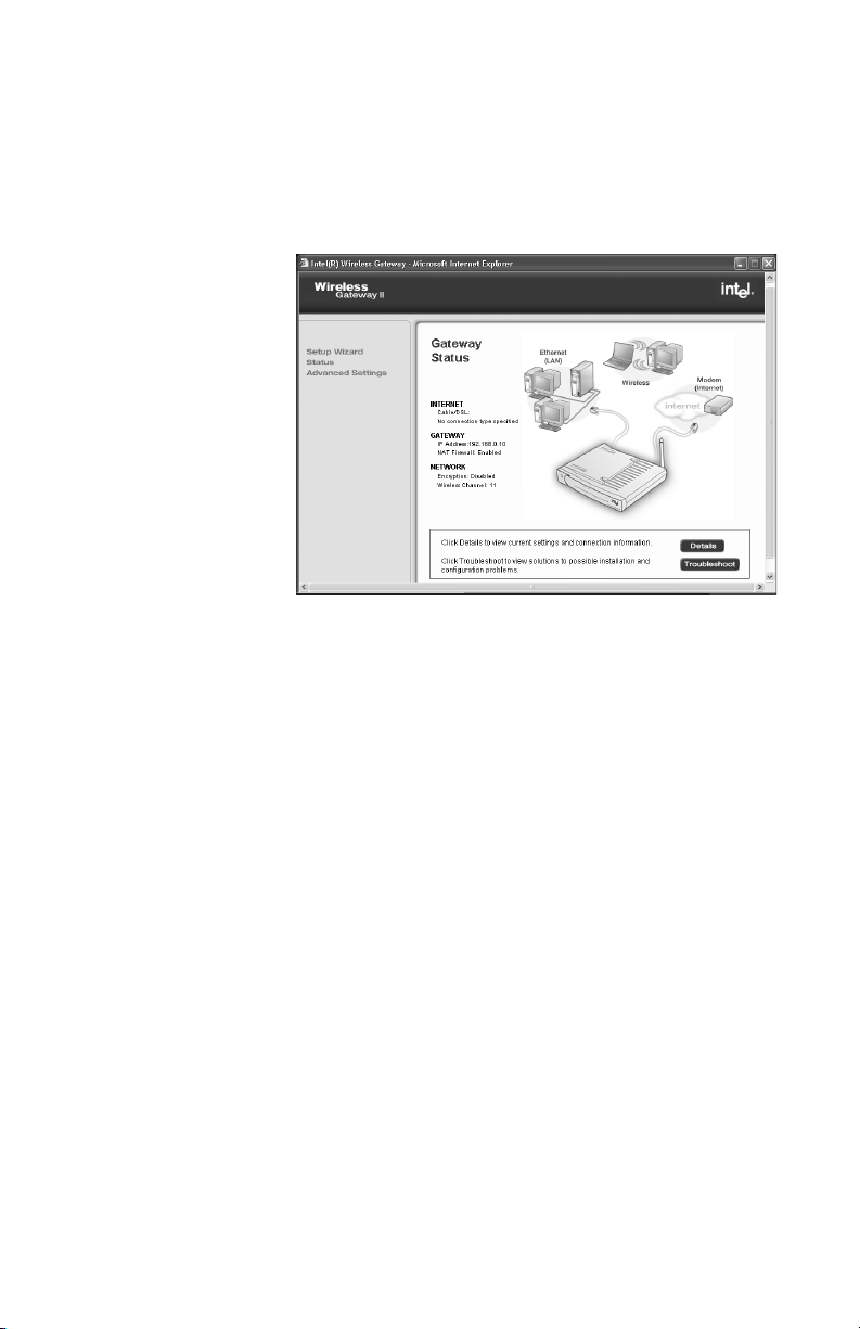
Chapter 5 – Troubleshooting
also perform diagnostics and troubleshooting to test the
gateway operation.
1 From the Wireless Gateway screen, click Status.
The following appears.
2 Click Details.
You will see the status of all your connections.
Using firmware troubleshooting tips
From the Status table, you can also use troubleshooting
tips to help you isolate connection problems. From the
Status screen, click Troubleshooting to see the
troubleshooting checklist. It provides information and tips
for two connection conditions:
• Your PC cannot connect to the Internet through the
gateway.
• You have one PC working, but you cannot wirelessly
connect other PCs to the gateway.
Using the system tools on your gateway
The System Tools screen provides easy-to-use tools for
troubleshooting. You can quickly reset your gateway,
71
Page 76

Chapter 5 – Troubleshooting
load default settings, or upgrade your configuration
software.
1 From the main Wireless Gateway screen, click
2 From the left column under Advanced Settings,
3 For additional information, see the following sections:
Advanced Settings.
The following appears.
click System Tools.
• Upgrading your firmware
• Loading default settings
• Resetting the gateway
Upgrading
your firmware
72
You can periodically check the Web to see if there are
any new upgrades to the configuration software. Using
the latest firmware upgrades can solve some
troubleshooting issues.
• For residential or small office applications when using
Intel AnyPoint Wireless II Network adapters, or thirdparty adapters, check for a gateway firmware
upgrade and instructions at:
www.apsupport.intel.com
Page 77

Chapter 5 – Troubleshooting
Loading
default
settings
Resetting the
gateway
When you click Default, your gateway restores the
factory settings and returns you to the initial Wireless
Gateway screen. Use the default settings if you want to
create a new configuration or start from known settings.
1 From the main Wireless Gateway screen, click
Advanced Settings.
2 Click System tools.
3 Click Default.
Your gateway now has the initial factory settings, but
any firmware upgrades remain.
Note The device IP address will be reset to
192.168.0.10
When you click Reset, you restart the gateway using the
current settings. The gateway shows the initial Wireless
Gateway screen. Click Reset from the System Tools
screen if you have mounted the unit on the wall or ceiling
and cannot physically access the Reset button.
1 From the main Wireless Gateway screen, click
Advanced Settings.
2 Click System tools.
3 Click Reset.
Your gateway restarts with your current settings.
73
Page 78

Chapter 5 – Troubleshooting
74
Page 79

Chapter 6
Glossary
This section contains a list of network and computer
related terms with definitions.
75
Page 80

Chapter 6 – Glossary
Glossary
802.11b A specific networking standard created by IEEE that
defines engineering design parameters for high-speed
wireless data transmission. The 802.11b standard allows
different manufacturers to create wireless products that
are compatible with each other.
Ad Hoc Mode Also called Peer-to-Peer mode
A software setting for 802.11b wireless adapters.
Adapter Also network adapter or NIC
A hardware device that allows your PC to connect to a
network.
Access Point
(AP)
ASCII
characters
DHCP Dynamic Host Configuration Protocol. A TCP/IP protocol
A hardware device that serves as a communications
“hub” for 802.11b wireless PCs and can also provide a
connection to a wired network. An AP can double the
range of wireless client PCs and provide enhanced
security.
Any printable alpha-numeric character.
that defines a way to automatically assign IP addresses
to computers on a network. IP addresses are managed
by a DHCP server on the network. When a computer
starts, it requests an IP address from the server. The
server leases an address for a set time. After that time,
the computer makes a new request. When a Windows*
computer is configured to obtain an IP address
automatically, it attempts to get an address from a DHCP
server. Windows 2000 and Windows NT* servers include
DHCP server software that can provide this service.
Network appliances that rely on TCP/IP often include a
DHCP server.
76
Page 81

Chapter 6 – Glossary
Driver (Device
Driver)
DNS Domain Name System. A naming service used to identify
Encryption A method of converting all of the information that is
Ethernet Ethernet is defined by the IEEE 802.3 standard. Ethernet
Special software programs required for any device to
install properly on a PC. Devices include network
adapters, printers, scanners, modems, audio cards, CD
drives, monitors, and so on. Drivers enable the device to
coordinate its activities with the PC to which it is
attached.
servers connected to the Internet. Every domain name is
unique. DNS servers maintain a database of names and
associated IP addresses, so Web users can browse to a
domain name and reach the server at the associated IP
address.
transmitted over a wireless network into a form that
cannot be read by unauthorized persons. Encryption
provides additional data security in 802.11b wireless
networks.
networks operate at 10 Mbps using CSMA/CD (CarrierSense Multiple Access with Collision Detection) to run
over 10BaseT cables.
Ethernet
address (MAC
address)
Firewall Software on a network gateway server that protects the
Each computer on an Ethernet network has its own
unique, pre-programmed Media Access Control (MAC)
address. This 12-digit hexadecimal address is encoded
into the circuitry of the computer's network adapter when
it is manufactured. Other devices on the network use this
address to identify the computer. This address is not the
same as the IP address that is assigned to computers on
TCP/IP networks. On these networks, the IP address is
associated with the MAC address to enable network
communication.
computers on a private network from the Internet. The
77
Page 82

Chapter 6 – Glossary
firewall can also control what Internet resources local
network computers can access.
Gateway A network device that provides a bridge or entrance to
another network. For example, a residential gateway can
allow a wireless network to connect to an Ethernet
network.
Hexadecimal A base-16 number system. That is, a numbering system
that counts 16 base unit numbers before adding a new
digit. Hexadecimal numbers use 0-9 and then the letters
A-F. For example, the letter A in hexadecimal represents
10 in decimal, F is 15 in decimal, and the hexadecimal
number 10 is 16 in decimal.
Hub The central connection point for network cables that
connect to computers or other devices on a network. With
an 8-port hub, you can connect cables to 8 computers
Infrastructure
Mode
IEEE The Institute of Electrical and Electronics Engineers.
78
A software setting for 802.11b wireless adapters allowing
connectivity to a central device, either a gateway or an
access point. The gateway or access point handles the
communication between PCs and often manages the
Internet connection. See Ad Hoc and Access Point.
ISP Internet Service Provider
An organization that provides access to the Internet.
Users connect with the ISP using a conventional or
broadband modem.
LAN Local Area Network
A computer network that serves users within a defined
location. The benefits include the sharing of Internet
access, files and equipment like printers and storage
devices. LANs use Ethernet cabling (10BaseT), existing
Page 83

Chapter 6 – Glossary
phone lines or radio waves to transmit data between the
PCs. LANs include home and small-business networks.
Mbps Megabits per second, a measure of data transmission
speed.
NAT Network Address Translation. A service that translates
your local private IP addresses to a public Internet
address so your privately addressed network can
connect to the public Internet. NAT simplifies network
setup and adds a measure of security to your network
because your private network addresses are never seen
on the Internet.
Peer-to-Peer
Mode
Profiles
(Network
Profiles)
Protocols
(Network
Protocols)
Resources
(Network
resources)
Roaming Moving seamlessly from one access point coverage area
SSID Service Set Identifier. To communicate with each other,
See Ad Hoc Mode.
A collection of software settings and network
identification information that is unique for each network.
Define the rules for all aspects of data communication,
just like a written language uses rules for spelling,
sentence structure, and so on. Protocols describe the
way data is organized, transmitted and received. The
TCP/IP protocol is one of the most common.
Software or hardware shared by the users of a network.
Resources can include software applications,
documents, digital pictures and music, games, numeric
data, and devices such as printers, modems and disk
drives.
to another with no loss in connectivity.
all wireless devices on the same network must use the
same SSID. The SSID allows two or more wireless
79
Page 84

Chapter 6 – Glossary
networks to function in the same vicinity without
interfering with each other. The SSID can be a word or a
combination of letters and numbers.
Subnet A distinct separate part of a computer network. Often,
computers in one building or location form a subnet.
Dividing a large network into subnets isolates network
traffic, enhances network performance, and provides a
mechanism for organizing the network in a logical
manner. You divide a network into subnets by connecting
network segments with a router. On a TCP/IP network, IP
routers connect subnets together.
Subnet mask A mask used to determine the subnet for an IP address.
IP addresses have two parts: a subnet address and the
computer address. The subnet mask determines what
part of the IP address is the subnet address. For
example, if you have a subnet mask of 255.255.0.0, the
first two numbers in your IP address are the subnet
address. The last two numbers are your computer's
address on the local network. Your computer uses the
subnet mask to decide whether to send data to another
computer on the local network, or to send the data to the
address specified by your default gateway. If the subnet
part of the address you are sending data to matches your
IP address, then your computer tries to send the data on
the local network. If these do not match, then the
computer you are sending data to is on another subnet
(probably on the Internet), so your computer sends the
data to your default gateway, and the gateway forwards it
on to the Internet.
80
Switch Similar to a hub, a switch is a central connection point for
network cables that connect to computers or other
network devices. However, when two devices
communicate through a switch, it sends signals directly
from one port to the other port, instead of transmitting to
all ports, like a hub does. You can connect a computer or
a hub to each port on a switch.
Page 85

Chapter 6 – Glossary
TCP/IP Transmission Control Protocol/Internet Protocol. The
protocol that computers use to communicate over the
Internet. TCP determines how a computer breaks up data
into small units, called packets, to be sent to another
computer, and how the receiving computer reassembles
the packets into a single file. IP determines how the
packets are routed across the Internet.
UPnP Universal Plug and Play (UPnP) is a standard that uses
Internet and Web protocols to enable devices such as
PCs, peripherals, and wireless devices to be plugged into
a network and automatically detect each other. With
UPnP enabled, when you add the gateway into the
network, the device configures itself for Internet access.
USB Universal Serial Bus
A peripheral bus standard that enables external devices
to attach to a PC while the PC is powered on. The flatshaped USB connector plugs into a similarly shaped
socket on the PC.
VPN Virtual Private Network. A VPN is a type of computer
network that functions like a private network but uses
public phone lines to carry data. VPNs use special
communication protocols and security techniques to
maintain privacy at a lower cost than is possible with
dedicated phone lines. The VPN software encrypts data
before sending it across the Internet to the other local
network. This keeps the data and the two local networks
secure, but lets them form a virtual network that includes
computers in two separate locations.
81
Page 86

Chapter 7
Specifications
The following technical specifications are for reference
purposes only.
82
Page 87

Chapter 7 – Specifications
Technical specifications
Actual product performance and compliance with local
telecommunications regulations may vary from country to
country. Intel Corporation only ships products that are
type approved in the destination country.
Specification Description
Interoperability Wireless: IEEE 802.11b, Wi-Fi* certified
Wired: IEEE 802.3 (Ethernet)
Data rate Up to 11 Mbps wireless
Up to 100 Mbps wired
Wireless Frequency 2.400 ~ 2.4835 GHz (subject to local
regulations)
Direct Sequence Spread Spectrum
Security 64-bit and 128-bit (WEP) encryption
NAT firewall
Access Control Lists
Kensington Lock capabilities
Connections Supports up to 254 unique addresses.
Up to 32 simultaneous connections (16
wireless and 16 wired)
Range Open space: up to 600 feet
Indoors: up to 300 feet
Ports Internet port: One 10 Mbps RJ-45
connection for broadband modem
LAN ports: Four 10/100 Mbps RJ-45
connections with auto-crossover
Antennas (two) External, adjustable, high -gain (1.5dBm)
with swivel neck adjustment
Internal, integrated F-type
LED Indicators Power, System status, Broadband
(Internet) Link, Wireless Link and Activity,
Ethernet (four)
83
Page 88

Chapter 7 – Specifications
Specification Description
Roaming Functions Gateway and Access Point configurations
NAT, DHCP server and client, PPPoE
Client, VPN pass-through
Network Protocol TCP/IP, IPX/SPX, NetBEUI
Mounting Back panel allows mounting to ceiling
Power adapter Input: AC 100-240V 50-60 Hz, 0.35A
Output: CD 5V, 2.0A
84
Page 89

Chapter 8
Regulatory Compliance Statements
This chapter contains the following agency notices:
■ Safety compliance statement
■ Emissions compliance statements
■ Canadian compliance statements
■ European Union compliance statements
85
Page 90

Chapter 8 – Regulatory Compliance Statements
Safety compliance statement
This product complies with the safety requirements for
Information Technology Equipment, and is Listed by
Underwriters Laboratories, Inc. to UL 60950 and CSA
C22.2 No. 950 for the U.S. and Canada.
Emissions compliance statements
This product has been tested and found to comply with
the limits for a Class B digital device pursuant to Part 15
of the FCC rules. These limits are designed to provide
reasonable protection against harmful interference when
the equipment is operated in a residential environment.
This product generates, uses, and can radiate radio
frequency energy and, if not installed and used in
accordance with the instruction manual, may cause
harmful interference to radio communications. However,
there is no guarantee that interference will not occur in a
particular installation. If this equipment does cause
harmful interference to radio or television reception,
which can be determined by turning this equipment off
and on, the user is encouraged to try to correct the
interference by one or more of the following measures:
86
• Change the direction of the radio or TV antenna.
• To the extent possible, relocate the radio, TV, or
other receiver away from the product.
• Plug the host computer into a different electrical
outlet so that the computer and the radio or TV are
on different electrical branch circuits.
This device complies with Part 15 of the FCC Rules.
Operation is subject to the following two conditions: (1)
This device may not cause harmful interference, and (2)
this device must accept any interference received,
including interference that may cause undesired
operation.
Page 91

Chapter 8 – Regulatory Compliance Statements
CAUTION
IF YOU MAKE ANY MODIFICATION TO THE
EQUIPMENT NOT EXPRESSLY APPROVED BY
INTEL, YOU COULD VOID YOUR AUTHORITY TO
OPERATE THE EQUIPMENT.
RF exposure compliance statements
Notice: Install or position the Intel®Wireless Gateway II
Model 1210 so that the antenna is at least 8 inches (20
cm.) from the user or other persons. Failure to locate the
antenna at this minimum distance may result in
exceeding the FCC limits for human exposure to RF
(radio frequency) energy. Also, do not operate in
conjunction with any other antenna or transmitters.
Canadian compliance statements
This Class B digital apparatus complies with Canadian
ICES-003.
[French] Cet appereil numérique de la classe B est
conforme à la norme NMB-003 du Canada.
This equipment complies with Canada 210. Operation is
subject to the following two conditions: (1) this device
may not cause interference, and (2) this device must
accept any interference, including interference that may
cause undesired operation of the device. To prevent
radio interference to the licensed service, this device is
intended to be operated indoors and away from windows
to provide maximum shielding. Equipment (or its transmit
antenna) that is installed outdoors is subject to licensing.
European Union compliance statements
We, Intel Corporation, declare under our sole
responsibility that the product:
Intel Wireless Gateway II Model 1210
87
Page 92

Chapter 8 – Regulatory Compliance Statements
is in conformity with all applicable essential requirements
necessary for CE marking, following the provisions of the
European Council Directive 89/336/EEC (EMC), Council
Directive 73/23/EEC (Safety/Low Voltage Directive), and
Council Directive 1999/5/EC (Radio Equipment and
Telecommunications Terminal Equipment).
The product is for distribution within all member states of
the EU with the following restriction:
France limited to 2446.5-2483.5 MHz indoor use.
The product is properly CE marked demonstrating this
conformity.
English This product follows the provisions of the
European Directive 1999/5/EC.
Dansk Dette produkt er i overensstemmelse med det
europæiske direktiv 1999/5/EC
88
Dutch Dit product is in navolging van de bepalingen van
Europees Directief 1999/5/EC.
Suomi Tämä tuote noudattaa EU-direktiivin 1999/5/EC
määräyksiä.
Français Ce produit est conforme aux exigences de la
Directive Européenne 1999/5/EC.
Deutsch Dieses Produkt entspricht den Bestimmungen
der Europäischen Richtlinie 1999/5/EC
Icelandic Þessi vara stenst reglugerð Evrópska
Efnahags Bandalagsins númer 1999/5/EC
Italiano Questo prodotto è conforme alla Direttiva
Europea 1999/5/EC.
Norsk Dette produktet er i henhold til bestemmelsene i
det europeiske direktivet 1999/5/EC.
Page 93

Portuguese Este produto cumpre com as normas da
Diretiva Européia 1999/5/EC.
Español Este producto cumple con las normas del
Directivo Europeo 1999/5/EC.
Svenska Denna produkt har tillverkats i enlighet med
EG-direktiv 1999/5/EC.
Product Ecology Statements
The following information is provided to address
worldwide product ecology concerns and regulations.
Chapter 8 – Regulatory Compliance Statements
Disposal
Considera-
tions
Disassembly
Instructions
This product contains the following materials that may be
regulated upon disposal: lead solder on the printed wiring
board assemblies.
Intel encourages its customers to recycle its products and
their components (e.g. batteries, circuit boards, plastic
enclosures, etc.) whenever possible. In the U.S., a list of
recyclers in your area can be found at: http://
www.eiae.org. In the absence of a viable recycling
option, products and their components must be disposed
of in accordance with all applicable local environmental
regulations.
This section is provided to aid in the disassembly and
recycling of this Intel product. Only technically qualified
persons should disassemble this product. Notice, no user
serviceable parts inside.
Tools needed:
• Small flathead screwdriver
• Small phillips head screwdriver
89
Page 94

Chapter 8 – Regulatory Compliance Statements
Disassembly steps:
1 Remove the label located at the bottom of the unit –
to access the single phillips head screw.
2 Remove the single phillips head screw located at the
bottom of the unit.
3 Locate two slots on the right-side of the unit.
4 By inserting a small flathead screwdriver first into one
of the slots then the other, slowly pry the top cover off
the unit.
5 You can now recycle the plastic case as well as the
internal circuit boards.
90
Page 95

Chapter 9
Index
A
Access Point mode 3, 35
Access point, defined
Ad hoc mode (see peer-to-peer)
Advanced settings
Advanced settings, changing
76
40
40
B
Back panel, described 8
Broadband modem
34
C
Cable/DSL settings 33
Changing
Access point mode
Advanced settings 41
Channel
Device settings
IP settings
Modem settings 34
Network Name
Wireless settings
Channel
Channels, changing 42
Configuration software
Connect to the gateway, how to
Connection status
Custom rule, creating
Custom Virtual Server settings 48
42
34
42
35
32
26
26
9, 23
24
25
49
D
Default settings 25, 73
Device settings, changing
DHCP server
DHCP, defined
Disable encryption
DNS, defined
Domain name 35
Domain name server
45
76
77
32
31
34
E
Enable DHCP 46
Encryption 4, 10
Enabling or disabling
Generating from password
Manually entering
Encryption keys, changing
Encryption, defined
30
28
29
28
77
76
ESSID (See SSID)
79
F
Factory settings 73
Firewall
Firmware, upgrading
Front panel, described
4
72
5
G
Gateway password, changing 40
Gateway, defined
78
H
Header length 42
Hexadecimal, defined
Host name 35
78
I
Infrastructure mode, defined 78
Internet sharing
IP address 34
IP settings, changing
IP subnet
IP subnet mask
ISP settings
4
34
34
36
11
L
LEDs, described 5
M
MAC address 35
Manual encryption
Modem settings, changing
11
34
N
Network Encryption, defined 77
Network ID Code 10
Network Name (See SSID)
Network Name, changing
79
27
P
Password encryption 11
Password protection
Preamble
Profiles, defined
42
40
79
91
Page 96

Index
R
Range 4
Resetting and restarting gateway
Routing information
Routing protocols 43
43
73
S
Save and restart 37
Service requirements
Setup wizard
Specifications
SSID, defined
SSID, see Network Name
System requirements
System tools 42, 71
23
5
83
79
27
4
T
Transfer rate 42
Troubleshooting information, where to find
12
Troubleshooting tips
71
U
Upgrading firmware 72
UPnP 53
UPnP, defined
UPnP, disabling
81
53
V
Viewing
Connection status
default settings
Virtual Server settings
25
25
46
W
WEP (see Network Encryption) 77
Wired Equivalent Privacy (see Network
Encryption)
Wireless settings
Wizard, setup 23
77
9, 26
92
 Loading...