

Page 1

21152 PCI-to- PCI Bridge
Evaluation Board
User’s Guide
July 1998
Order Number: 278127-001
Page 2

Information in this document is provided in connection with Intel products. No license, express or implied, by estoppel or otherwise, to any intellectual
property rights is granted by this document. Except as provided in Intel’s Terms and Conditions of Sale for such products, Intel assumes no liability
whatsoever, and Intel disclaims any express or implied warranty, relating to sale and/or use of Intel products including liability or warranties relating to
fitness for a particular purpose, merchantability, or infringement of any patent, copyright or other intellectual property right. Intel products are not
intended for use in medical, life saving, or life sustaining applications.
Intel may make changes to specifications and product descriptions at any time, without notice.
Designers must not rely on the absence or characteristics of any features or instructions marked "reserved" or "undefined." Intel reserves these for
future definition and shall have no responsibility whatsoever for conflicts or incompatibilities arising from future changes to them.
The 21152 may contain design defects or errors known as errata which may cause the product to deviate from published specifications. Current
characterized errata are available on request.
Contact your local Intel sales office or your distributor to obtain the latest specifications and before placing your product order.
Copies of documents which have an ordering number and are referenced in this document, or other Intel literature may be obtained by calling 1-800-
548-4725 or by visiting Intel’s website at http://www.intel.com.
Copyright © Intel Corporation, 1998
*Third-party brands and names are the property of their respective owners.
21152 PCI-to-PCI Brid ge Evaluation Board User’s Guide
Page 3

Contents
1 Introduction.........................................................................................................................1
1.1 Overview...............................................................................................................1
1.2 Features................................................................................................................1
1.3 Major Components................................................................................................2
1.4 Jumpers.................................................................................................................3
1.5 Secondary Slot Numbering and IDSEL Mappin g .................................................. 3
1.6 Typical Conf igu r a tions...... ...................... ............................... .............................. ..4
2 Installa tion................... .............................. ............................... ............................... ......... ..1
2.1 Specifica tions............................. ............................... .............................. ..............1
2.2 Hardware Requirements .......................................................................................1
2.3 Software Requirements.........................................................................................1
2.4 Installation Procedure............................................................................................2
3 Interrupt Routing.................................................................................................................1
4 Secondary Bus Arbitration..................................................................................................1
A Kit Contents ........................................................................................................................1
Support, Products, and Documentation .......................................... ....... ..... ....... .. .......... ....3
21152 PCI-to-PCI Bridge Evaluation Board User’ s Gu id e iii
Page 4

Figures
Tables
1-1 EB152 Major Components.................................................................. ....... ..... ......2
1-2 Secondary PCI Slot Numbering............................................................................3
1-3 EB152 with One Secondary Bus Option Card ......................................................4
1-4 EB152 with Two Secondary Bus Option Cards....................................................4
1-5 Tri-Level with Two EB152s ................................................................................... 5
1-6 Four PCI Buses in a Tri-Level Hierarchy...............................................................5
4-1 Arbitration Jumpers...............................................................................................2
1-1 Jumper Connections .............................................................................................3
3-1 Interrupt ORing......................... ............................... ............................... ...............1
3-2 Interrupts from Devices to EB152 Fingers............................................................2
4-1 Internal Arbitration Jumper Positions....................................................................2
4-2 External PAL Arbitration Jumper Positions...........................................................3
iv 21152 PCI-to-PCI Brid ge Evaluation Board User’s Guide
Page 5

Introduction
This document describes the Intel 21152 PC I-to-PCI Bridge Evaluation Boar d (also referred to as
the EB152). The EB152 is an evaluation and development board for systems based on the Intel
21152 PCI-to-P CI Bridge chip (the 21152).
Intel’s 21152 is a second-generation PCI-to-PCI bridge an d is fully compliant with the electr ical
and protocol requirements of the PCI-to-PCI Bridge Architecture Specification, Revision 2.1, and
the PCI-to-PCI Bridge Archit ecture Specific ation, Revision 1.0. The 21152 provides full support
for delayed transactions, which enables the buffering of memory read, I/O, and configuration
transactions . The 21152 has separate posted write, read data, and delayed trans action queues with
significantly more buffering capability than first-generation bridges.
For detailed info rmation about the 21152, refer to the 21 152 PCI-to-PCI Bridge Data Sheet.
1.1 Overview
This chapter provides an overview of the 21152 PCI-to-PCI Bridge Evaluation Board EB152 and
includes inf orm ation about the following topic s :
• Jumper location
1
• Secondary slot numbering and IDSEL mapping
• Typical configurations
The EB152 is a unive rs al PCI exp ansi on board th at is used t o eval uate t he opera tion of t he 21152 in
various configurations, and with a variety of PCI devices. The EB152 can be used to perform the
following functions:
• Develop initia lization code to configu re a PCI-to-PCI bridge and the PCI devices behind the
bridge
• Evaluate the operation of a PCI-to-PCI bridge with a variety of PCI devices attached to the
secondary bus
• Build an d ev al u at e a fl ex i b le hi er ar c h y f or mu ltiple PCI bu ses
1.2 Features
The EB152 has the following features:
• Complies fully wit h the protocol and electrical standards of the PCI Local Bus Specification,
Revision 2.1.
• Includes a 21152 PCI-to-PCI Bridge that prov ides bridging between a primary and seco ndary
bus.
• Includes a primary PCI bus that plugs into any 5-V or 3.3-V PCI option card slot.
21152 PCI-to-PCI Bridge Evaluation Board User’s Guide 1-1
Page 6
Introduction
• Supports four secondary 5 V PCI bus option card slot s.
• May be built with 3.3-V second ary PCI ca rd slots. If you are interested in this option, call the
Intel Informa tion Line (see, Support, Products, and Documentation).
• Supports an optional external secondary bus arbiter.
• Supports multiple levels of PCI bus hierarchy
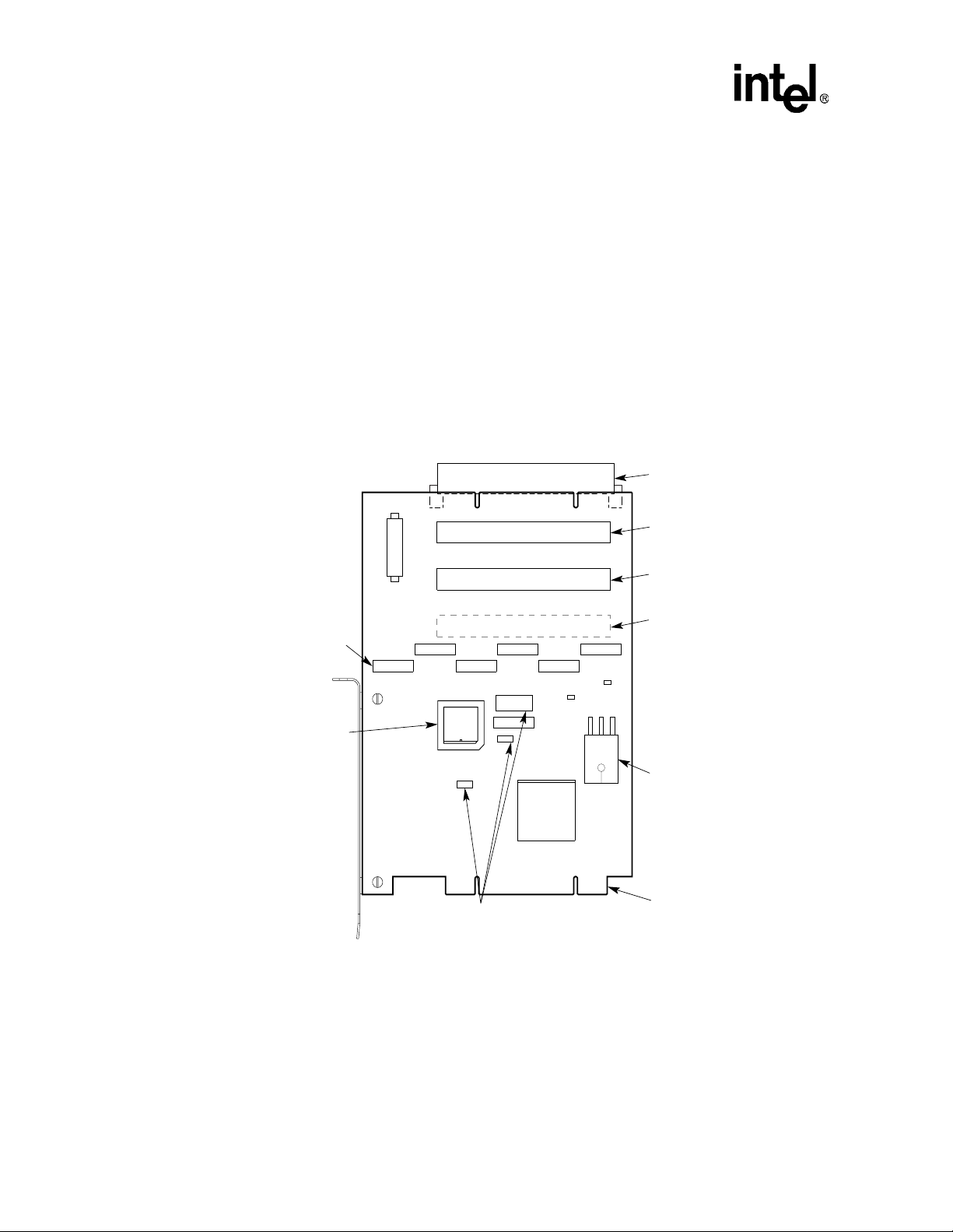
1.3 Major Components
Figure 1-1 shows the major components on the EB15 2.
Figure 1-1. EB152 Major Components
Viewed from Side 1
J8_J12, J2, and
J1 _ Signal
Monitoring Pods
E3 _ Socket for
Optional PAL to
Control Secondary
Bus External
Arbitration
J6
J3
J13
J5
J4
J9
J8
E3
W1
W1, W4, J7 _ Secondary Bus
External/Internal Arbitration
Configurable Jumpers
J11
J10
W4
J12
J7
J1
21152
W5
J2
E4
W7
PCI Option Card Slot
(PCI Device 7)
PCI Option Card Slot
(PCI Device 6)
PCI Option Card Slot
(PCI Device 5)
PCI Option Card Slot
(PCI Device 4)
E2 _ Optional
High-Current 3.3-V
Voltage Regulator
for Boards with 3.3-V
Secondary Connectors
Primary Bus
Connector
(to Host System
Motherboard)
LJ-05028.AI4
1-2 21152 PCI-to-PCI Bridge Evaluation Board User’s Guide
Page 7
1.4 Jumpers
The EB152 provides 10 jumpe rs that can be used for debugging and for special evaluation tests.
The jumpers can be used for monit ori ng CLK sign als and 21 1 52 secondary PCI signal s. Addit ion al
optional jump ers control secondary bus arbitration.
Table 1-1 shows the connections required to allow observation of these signals at scope pod
connector pins.
Table 1-1. Jumper Connections
Jumper Description
J1 This jumper monitors the foll owing signals:
J2, J8 through J12 Logic analyzer pods can be plug ged into thes e jumpers for
W1, W4, J7 These jumpers control secondary bus arbitration. Chapter 4, Secondary Bus
Introduction
p_clk (PCI clock)
s_clk_o<4:1> (four secondar y PCI clocks)
s_clk_o<0> (fed back to the s_clk input pin)
s_gnt_l<2> and s_gnt_l<3> .
monit oring 21152 secondary PCI sig nals.
Arbitration, provides information about configuring these jumpers.
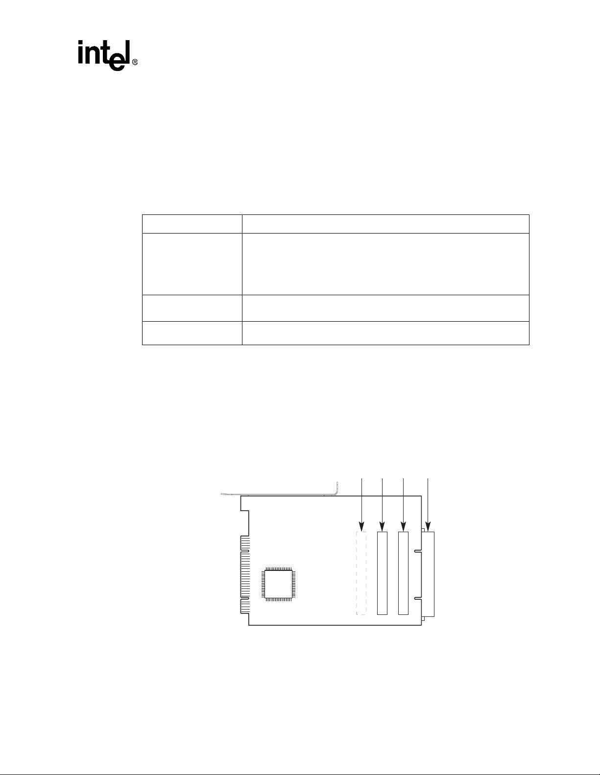
1.5 Secondary Slot Numbering and IDSEL Mapping
The PCI secondary bus opt ion card s lots are mapped to PCI device number s 4, 5, 6, and 7 as shown
in Figure 1-2. The secondary bus lines s_ad<20:23> are used as se co ndary IDSE L lines.
Figure 1-2. Secondary PCI Slot Numbering
PCI Device Numbers
456
PCI Option Card Slots
7
LJ-04468.AI4
21152 PCI-to-PCI Bridge Evaluation Board User’s Guide 1-3
Page 8

Introduction
1.6 Typical Configurations
The EB152 suppor ts var ious PCI c onfi gurati ons with dif fe rent typ es of de vices. Figur e 1-3 through
Figure 1-6 show examples of PCI configurations.
The primary bus con nec tor attaches to a PCI slot on the mother board of the host system or to a
secondary PCI bus slot on another EB152. A 5-V or universal PCI option card, or another EB152,
can be plugged in to any one of the four secondary bus option card slot s.
Figure 1-3 shows the EB152 with one secondary bus option card.
Figure 1-3. EB152 with One Secondary Bus Option Card
Host System
Motherboard
EB152
Option Card
21152
Figure 1-4 shows the EB152 with two secondary bus option cards
Figure 1-4. EB152 with Two Secondary Bus Option Cards
Host System
Motherboard
EB152
21152
PCI
Device
Option Card
PCI
Device
Option Card
PCI
Device
LJ-05029.AI4
LJ-05030.AI4
1-4 21152 PCI-to-PCI Bridge Evaluation Board User’s Guide
Page 9
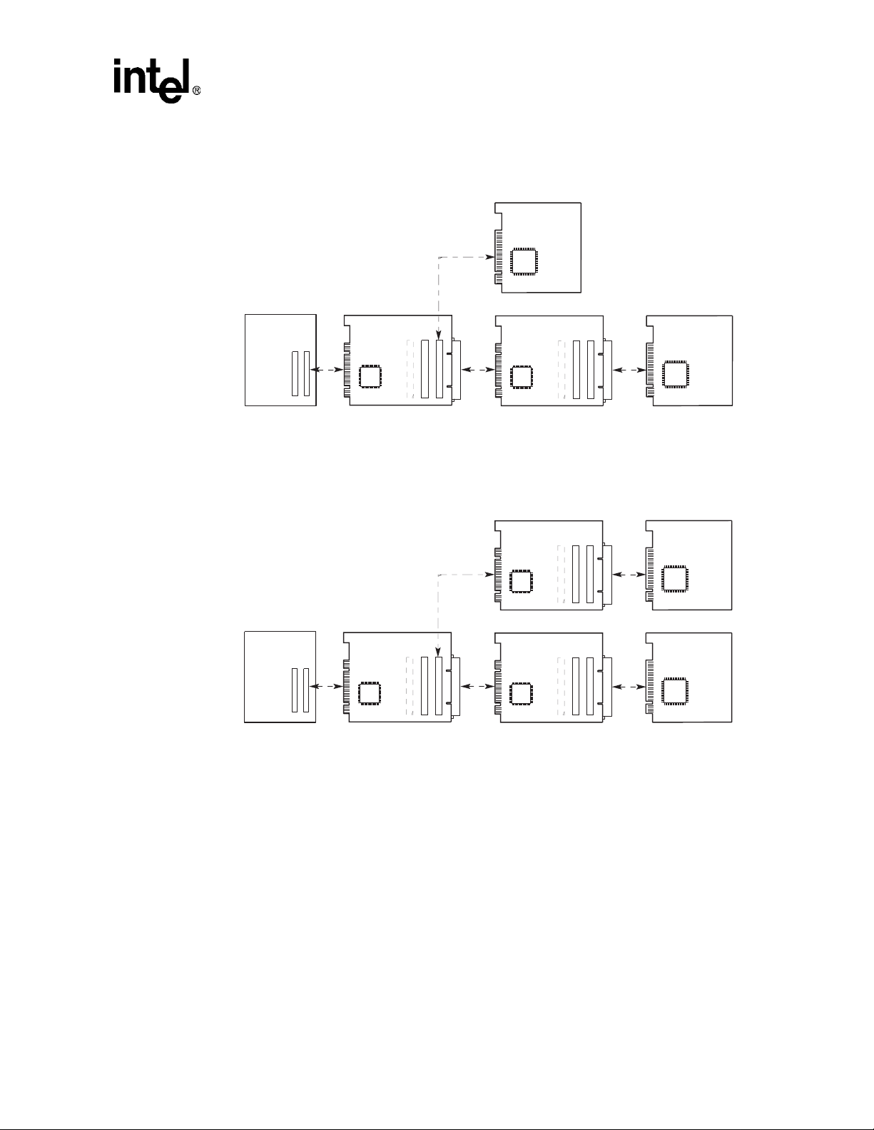
Figure 1-5 shows a tri-level bus with two EB152s.
Figure 1-5. Tri-Level with Two EB152s
Host System
Motherboard
EB152
Option Card
PCI
Device
EB152
Introduction
Option Card
21152
Figure 1-6 shows four PCI buses in a tri-level hierarchy.
Figure 1-6. Four PCI Buses in a Tri-Level Hierarchy
Host System
Motherboard
EB152
21152
21152
21152
21152
EB152
EB152
PCI
Device
LJ-05031.AI4
Option Card
PCI
Device
Option Card
PCI
Device
LJ-05032.AI4
21152 PCI-to-PCI Bridge Evaluation Board User’s Guide 1-5
Page 10

Page 11

Installation
This chapter provi des information about the EB152 speci f ications and the hardware and software
requirements for using the EB152. It also describes how to install the EB152.
2.1 Specifications
The physical and power specifications for the EB152 are as follows:
Dimensions:
Height: 20.0 cm (7.90 in)
Width: 13.2 cm (5.20 in)
Power Requirements:
dc amps @ 5 V: 2.0 A (maximum)
2.2 Hardware Requirements
The following equipment is required to use the EB152:
2
• A computer system equipped with a PCI motherboard
• A PCI expansion slot on the motherboard that is equipped for the 5 V or 3.3 V environment
2.3 Software Requirements
To test the EB152 in x86 DOS or Windows systems, system BIOS must include autoconfiguration
code for PCI-to-PCI bridges. If the system BIOS does not include this functionality, contact your
BIOS vendor to obtain code with PCI-to-PCI bridge autoconfiguration support.
The EB152 kit provides a DOS utility that can be used to configure the PCI-to-PCI bridge. The
diskette included in the EB152 kit contains the DOS utility and a README.TXT file that explains
how to use it.
21152 PCI-to-PCI Bridge Evaluation Board User’s Guide 2-1
Page 12

Installation
2.4 Installation Procedure
Figure 1-1 illustrates the EB152 and shows the location of components refe rred to in this section.
Install the EB152 as f o llows:
1. Power down the host system that will contain the EB152.
2. Place the motherboard with the associated support devices on a bench if mechanical
constrai nts do not allow testing of the EB152 and the expansion slots inside the syste m box.
3. Configure your system as follows:
a. Insert the card edge of the EB152 into a PCI slot.
b. Insert a 5-V or unive rsal option P CI card i nto any or each of t he four s econdary bus option
card slots. Section 1.4 shows examples of typical PCI configurations.
4. Power up the system.
5. Verify autoc onfiguration of the 21152 and of any devices that are plugged in as fol lows :
a. Verify that system BIOS or firmware detects and configures the PCI devices downstream
of the 21152. If system BIOS is not available, use the DOS utility provided with the
EB152 kit to configure the devices downstream of the 21152, and verify proper
configuration.
b. Install de vice drivers for any PCI devices that are downs tream the 21152, and veri fy
proper configuration of those devices.
6. If desired, moni tor bridge secondary PCI control signals by connecting a logic analyzer to
pods J2 and J8 through J12.
2-2 21152 PCI-to-PCI Bridge Evaluation Board User’s Guide
Page 13

Interrupt Routing
This chapter describes the way in which interrupts are routed. This information is provided as a
reference for designers .
Because a total of 16 interrupts are connected to the secondary bus PCI slots (INTA#, INTB#,
INTC#, and INTD# for each slot) and only four interrupts are driven to the card edge, the 16
incoming interrupts must be combined. This ORing of interrupts is perfo rmed in accordance with
the PCI-to-PCI Bridge Architecture Specification.
Table 3-1 shows the ORing of interrupts.
Table 3-1. Interrupt ORing
3
Device Number Interrupt Pin
on Device
4 INTA#
INTB#
INTC#
INTD#
5 INTA#
INTB#
INTC# I
INTD#
6 INTA#
INTB#
INTC#
INTD#
7 INTA#
INTB#
INTC#
INTD#
Interrupt Pin
on Board Connector
INTA#
INTB#
INTC#
INTD#
INTB#
INTC#
INTD#
INTA#
INTC#
INTD#
INTA#
INTB#
INTD#
INTA#
INTB#
INTC#
In accordance with the PCI-to-PCI Bridge Arch itecture Specification, Revision 1.0, interrupts of
the devices on the secondary slots are wire ORed and routed to PCI fingers of the EB152.
21152 PCI-to-PCI Bridge Evaluation Board User’s Guide 3-1
Page 14

Interrupt Routing
Table 3-2 lists the interrupts from the de vices on the secon dary slots to the interrupts on the EB 152
fingers.
Table 3-2. Interrupts from Devices to EB152 Fingers
Interrupts from Devices on
Secondary Slots
INTA4 L
INTD5 L
INTC6 L
INTB7 L
INTB4 L
INTA5 L
INTD6 L
INTC7 L
INTC4 L
INTB5 L
iNTA6 L
INTD7 L
INTD4 L
INTC5 L
INTB6 L
INTA7 L
Interrupts on EB152 Fingers
INTA L
INTB L
INTC L
INTD L
Note: In the first column of Table 3-2, the number after each interrupt pin is the device number of the
devices in the s econdary slots. The L indicates that the assertion level is low.
3-2 21152 PCI-to-PCI Bridge Evaluation Board User’s Guide
Page 15

Secondary Bus Arbitration
This chapter describes the use of jumpers to te st 21152 secondary bus arbitration, an optional
programmable feature. For more detailed information about the 21152 arbi ter, refer to the 21152
PCI-to-PCI Bridge Data Sheet.
The EB152 has two secondary bus arbiter systems:
• An internal arbiter implemented in the 21152 that supports four external masters in addition to
the 21152
• An optional external arbiter implemented in an AMD MACH210A programmable device
The default setting is internal arbitration. The internal 21152 arbiter implements a 2-level
programmable rotat ing mode algori thm. Second ary bus par king is don e at the las t master to use the
bus.
The internal arbiter can be disabled, and an external arbiter can be used instead for secondary bus
arbitration. The EB152 provides a socket for an optional PAL (labeled E3 in Figure 4-1) to control
secondary bus arbitration. If a different external arbiter is used where parking is done at one of the
PCI slots, a PCI devic e must be ins talle d in t hat slot. To change the def ault, configure the se condary
bus arbiter system using jumpers J7, W4, and W1.
Figure 4-1 shows t he l oca ti on o f t he a rbi tr at ion jum per s, an d Table 4-1 and Table 4-2 describe their
operation.
4
All jumper positions assume that the EB152 is positioned with the components fa cing forward and
the car d ed ge facing down.
21152 PCI-to-PCI Bridge Evaluation Board User’s Guide 4-1
Page 16
Secondary Bus Arbitration
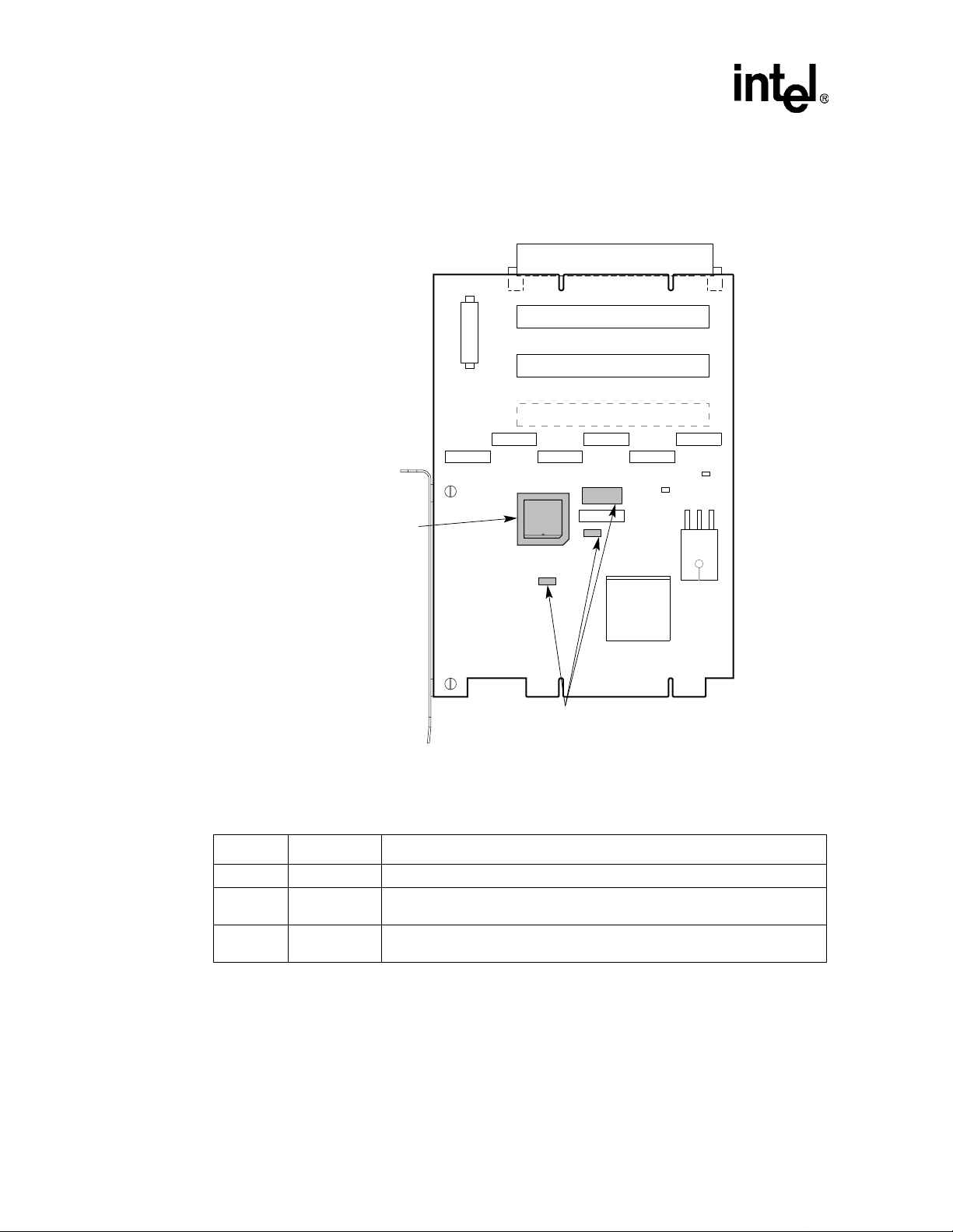
Figure 4-1. Arbitration Jumpers
Viewed from Side 1
J6
J3
J13
J5
J4
J8
E3 _ Socket for
Optional PAL to
Control Secondary
Bus External
Arbitration
W1, W4, J7 _ Secondary Bus
External/Internal Arbitration
Configurable Jumpers
Table 4-1 describes the operation of internal arbitration jumpe r s .
Table 4-1. Internal Arbitration Jumper Positions
Jumper Position Description
J7 Bottom Selects the 21152 as the source of secondary grant sign als.
W4 Left
W1 Left
Selects the board signal sreq<0>_l (device 4 req ue st si gnal ) to dri ve th e 2 1152
s_req_l<0> input.
Ties s_cfn_l low, which enables the 21152 internal arbiter. When the
seconda ry PCI bus is idle, parking is at the 21152.
J9
W1
E3
J10
W4
J11
J12
J7
J1
21152
J2
W7
W5
E4
LJ-05127.AI4
4-2 21152 PCI-to-PCI Bridge Evaluation Board User’s Guide
Page 17

Table 4-2 describes the operation of jumpers for external arbitration with PAL.
Table 4-2. External PAL Arbitrati on Jum per Positions
Jumper Position Desc ription
J7 Top Selec ts the PAL as the source of secon dary grants.
W4 Right Selects the board signal gt_out<4> (the external secondary grant to the
21152) to drive the 21152 s_req_l<0> input.
W1 Right Ties s_cfn_l high, which disables th e21152 internal arbiter and causes the
following reconfigurations:
Signal s_gnt_l<0> becomes the se condary bus req uest.
Signal s_req_l<0> becomes the secondary bus grant.
The PAL parks the secondary bus at the 21152.
Secondary Bus Arbitration
21152 PCI-to-PCI Bridge Evaluation Board User’s Guide 4-3
Page 18

Page 19

Kit Contents A
This appendix lists the contents of the Intel Semiconductor 21152 PCI-to-P CI Bridge Evaluation
Kit.
The Intel Semiconductor 21152 PCI-to-PCI Bridge Evaluation Kit contains the following
materials:
• A Intel Semiconductor 21152 PCI-to-PCI Bridge Evaluation Board (EB152)
• A diskette that con tains an MS-DOS utility for configuring the EB152
• A documentation package that includes the following:
— 21152 PCI -to-PCI Bridge Data Sheet
— 21152 PCI- to-PCI Bridge Product Brief
— 21152 PCI - to-PCI Bridge Configuration Application Note
— 21152 PCI -to-PCI Bridge Hardware Implementation Application Note
— 21152 PCI-to-PCI Bridge Evaluation Board User’s Guide
— 21152 Evaluation System BIOS Letter
— 21152 PCI Evaluation Boar d S chematics
— 21152 Evaluation Board Vendor Parts List
— SPICE model kit containing a Level 28 21152 SPICE model and a pplication note
— Warranty Agr eement/Registration Card
21152 PCI-to-PCI Bridge Evaluation Board User’s Guide A-1
Page 20

Page 21

Support, Products, and Documentation
If you need technical support, a Pr odu ct Cat alog , or hel p deci din g which d ocume ntati on bes t meets
your needs, visi t the Intel W orld Wide Web Internet site:
http://www. inte l.com
Copies of document s th at have an ordering number and are referenced in this document, or other
Intel literature may be obtained by calling 1-800-332-2717 or by visiting Intel’s website for
developers at:
http://developer.intel.com
You can al so con ta ct the In tel Ma ssa chus et ts Inf or matio n Li ne or the Int el Mass achus et ts Cu st omer
Technology Center. Please use the following information lines for support:
For documentation and general information:
Intel Massachusetts Information Line
United States: 1–800–332–2717
Outside United States: 1–303-675-2148
Electronic mail address: techdoc@intel.co m
For technical support:
Intel Massachusetts Customer Technology Center
Phone (U.S. and international): 1–978–568–7474
Fax: 1–978– 568–6698
Electronic mail address: techsup@intel.com
 Loading...