

Page 1

Intel® 21143 PCI/CardBus 10/
100Mb/s Ethernet LAN Controller
Design Guide
July 2002
Order Number: 278588-001
Page 2

Information in this document is provided in connection with Intel® products. No license, express or implied, by estoppel or otherwise, to any intellectual
property rights is granted by this document. Except as provided in Intel’s Terms and Conditions of Sale for such products, Intel assumes no liability
whatsoever, and Intel disclaims any express or implied warranty, relating to sale and/or use of Intel products including liability or warranties relating to
fitness for a particular purpose, merchantability, or infringement of any patent, copyright or other intellectual property right. Intel products are not
intended for use in medical, life saving, or life sustaining applications.
Intel may make changes to specifications and product descriptions at any time, without notice.
Contact your local Intel sales office or your distributor to obtain the latest specifications and before placing your product order.
Copies of documents which have an ordering number and are referenced in this document, or other Intel literature may be obtained by calling
1-800-548-4725 or by visiting Intel’s website at http://www.intel.com.
Copyright © Intel Corporation, 2002
*Other names and brands may be cla imed as the property of others.
2 Design Guide
Page 3

Contents
Contents
1.0 Functional Overview........................................................................................................................5
1.1 21143 Overview....... ...... ....... ...... ....... ...................................... ....... ...... ....... ...... ....... ............5
1.2 Network Interface..................................................................................................................5
1.3 MII-Based PHY Block Diagram.............................................................................................6
1.4 SYM-Based PHY Block Diagram..........................................................................................6
2.0 21143 Ports .....................................................................................................................................7
3.0 Network Connection ........................................................................................................................9
3.1 10BASE-T Twisted-Pair Network Port..................................................................................9
3.2 100-Ready Designs ............................................................................................................12
3.2.1 Internal Optional Daughtercard..............................................................................13
3.2.2 Description of 100-Ready Daughtercard Block Diagram .......................................13
3.2.3 100-Ready External Module Design ......................................................................14
3.2.4 Description of 100-Ready External Module Block Diag ram...................................1 4
3.2.5 MII/SYM Pin Listing ...............................................................................................14
3.3 AUI Network Port................................................................................................................15
3.4 Media-Specific Components...............................................................................................18
4.0 21143 Requirements .....................................................................................................................19
4.1 Unused JTAG Port Requirements ......................................................................................19
4.2 Current Reference and Capacitor Input Requirements ......................................................19
4.3 Crystal and Crystal Oscillator Connections ........................................................................20
5.0 Signal Routing and Placement ......................................................................................................21
5.1 Ground and Power Planes..................................................................................................21
5.1.1 3.3 V Power Supply ...............................................................................................22
5.2 LED Status Signals.............................................................................................................22
6.0 Design Considerations ..................................................................................................................23
6.1 Designing the Ethernet Corner on Motherboards...............................................................23
6.2 Suggestions for FCC Compliance ......................................................................................23
6.2.1 Suggestions for Quiet Ground and Power Planes .................................................23
6.2.2 Suggestions for Routing ........................................................................................24
Figures
1 MII-Based PHY Design.................................................................................................................6
2 SYM-Based PHY Design..............................................................................................................7
3 10BASE-T Network Connection with Buffers..............................................................................10
4 10BASE-T Network Connection Without Buffers........................................................................11
5 Minimum Components Required for 10BASE-T........................................................................12
6 10BASE-T 100-Ready Daughtercard Block Diagram.................................................................13
7 10BASE-T 100-Ready External Module Block Diagram.............................................................14
8 AUI 10BASE5 Network and Pin Connections.............................................................................16
Design Guide 3
Page 4
Contents
9 AUI 10BASE2 Network Connection............................................................................................17
10 21143 External Component Connections...................................................................................20
11 LED Time-Stretcher Circuit.........................................................................................................22
Tables
1 Signal gep<0>/aui_bnc Description..............................................................................................5
2 AUI Signals...................................................................................................................................7
3 Twisted-Pair Signals.....................................................................................................................7
4 MII Signals............. ...... ....................................... ....... ...... ...... ....... ...... ....... ...... ....... ..... .................8
5 SYM Signals.................................................................................................................................8
6 Internal vs. External Design Features .......................................................................................13
7 MII/SYM Pinout...........................................................................................................................14
8 10BASE-T Media-Specific Components.....................................................................................18
9 10BASE2 and 10BASE5 Media-Specific Components ..............................................................18
10 Pin Requirements When Not Using the JTAG Port ....................................................................19
11 Current Reference and Capacitor Inputs....................................................................................19
12 Crystal Specifications .................................................................................................................20
Revision History
Date Revision Description
July 2002 001 First release.
4 Design Guide
Page 5

Intel® 21143 PCI/CardBus 10/100Mb/s Ethernet LAN Controller
This design guide prov ides a description of how to implement 100BASE-TX and 10BASE-T
network connections using the 21143 PCI/CardBus 10/100 Mb/s Ethernet LAN Controller
(referred to as the 21143).
While this document will not provide specific recommendations for physical layer devices, it will
provide design recommendations and layout recommendations.
This application note prov ides a description of how to implement 100BASE-TX and 10BASE-T
network connections using the 21143 PCI/CardBus 10/1 00 Mbs/s Ethernet LAN Controller
(referred to as the 21143).
1.0 Functional Overview
This section provides an overview of the 21143 and the implementation of 100 Mb/s and 10 Mb/s
network connections using MII-based or SYM-based PHY devices.
1.1 21143 Overview
The 21143 is a single-chip bus master Ethernet/Fast Ethernet device that supports direct memory
access (DMA) and has direct interfaces to both the CardB u s and the PCI local bus. The 21143
implements a direct interface to the CardBus or PCI bus through a single 50-pin connection, which
consists of the control and address/data signals.
The 21143 provides a complete implementation of the IEEE 802.3 Ethernet specification. This
includes the attachment unit interface (AUI), twisted-pair (10BASE-T) interface, MII SYM port
interface, and the interface through the media access control (MAC) layer that creates a direct
interface to the PCI bus.
The PCI interface utilizes only about 10% of the bus bandwidth during fully networked operation
for 100 Mb/s Fast Ethernet reception or transmission. This bus master design results in high
throughput between the system and the network.
1.2 Network Interface
The 21143 physical layer desi gn sup po rts AUI dro p cable Ethernet and 10BASE-T twisted-pair
(TP) Ethernet connections. The 21143 gep<0>/aui_bnc (pin 100), which is software controlled,
provides for a connection of either the AUI (10BASE5) or BNC (10BASE2) network connector.
Table 1 describes the function of this pin.
Table 1. Signal gep<0>/
Program State Function
0 AUI port enabled; BNC port disabled.
1 BNC transceiver (or DC-to-DC converter) enabled; AUI port disabled
AUI signals interface with the Manchester encoder/decoder portion of the 21143. The 21143
supports 10BASE5 thickwire and 10BASE2 ThinWire connections. The 10BASE2 connection
requires an external transceiver.
aui_bnc Description
Design Guide 5
Page 6
Intel® 21143 PCI/CardBus 10/100Mb/s Ethernet LAN Controller
The 21143 implements the 100BASE-T MII layer and the 100/10 Mb/s Ethernet MAC layer. The
21143 provides a dual network interface for both a 100BASE-T and a 10 Mb/s Ethernet. At the
100BASE-T port, the 21143 supports the industry-standard MII for any 100BASE-T
implementation.
The 21143 is fully compl iant with the MII specifications (as defined in IEEE 802.3). The MII is a
nibblewide, general interface, that can be used with various physical interfaces, such as 100BASETX, 100BASE-T4, shielded twisted-pair (STP), and fiber. It also supports dual rates of speed
(10 Mb/s and 100 Mb/s).
The 21143 includes special support for 100BASE-TX networks by including the PCS section
(scrambler and 5B/4B coding/decoding). Integrati ng the 10BASE-T ENDEC with the 100 Mb/sonly SYM-based PHYs enables full support for a 10/100-implementation.
1.3 MII-Based PHY Block Diagram
Figure 1 is a block diagram of a 10BASE-T and 100BA SE-T singl e-connecto r network connectio n
using a MII-based PHY device with the 21143.
MII-based PHY devices are provided by Intel, Integrated Circuit Systems*, National
Semiconductor*, Seeq*, and TDK*.
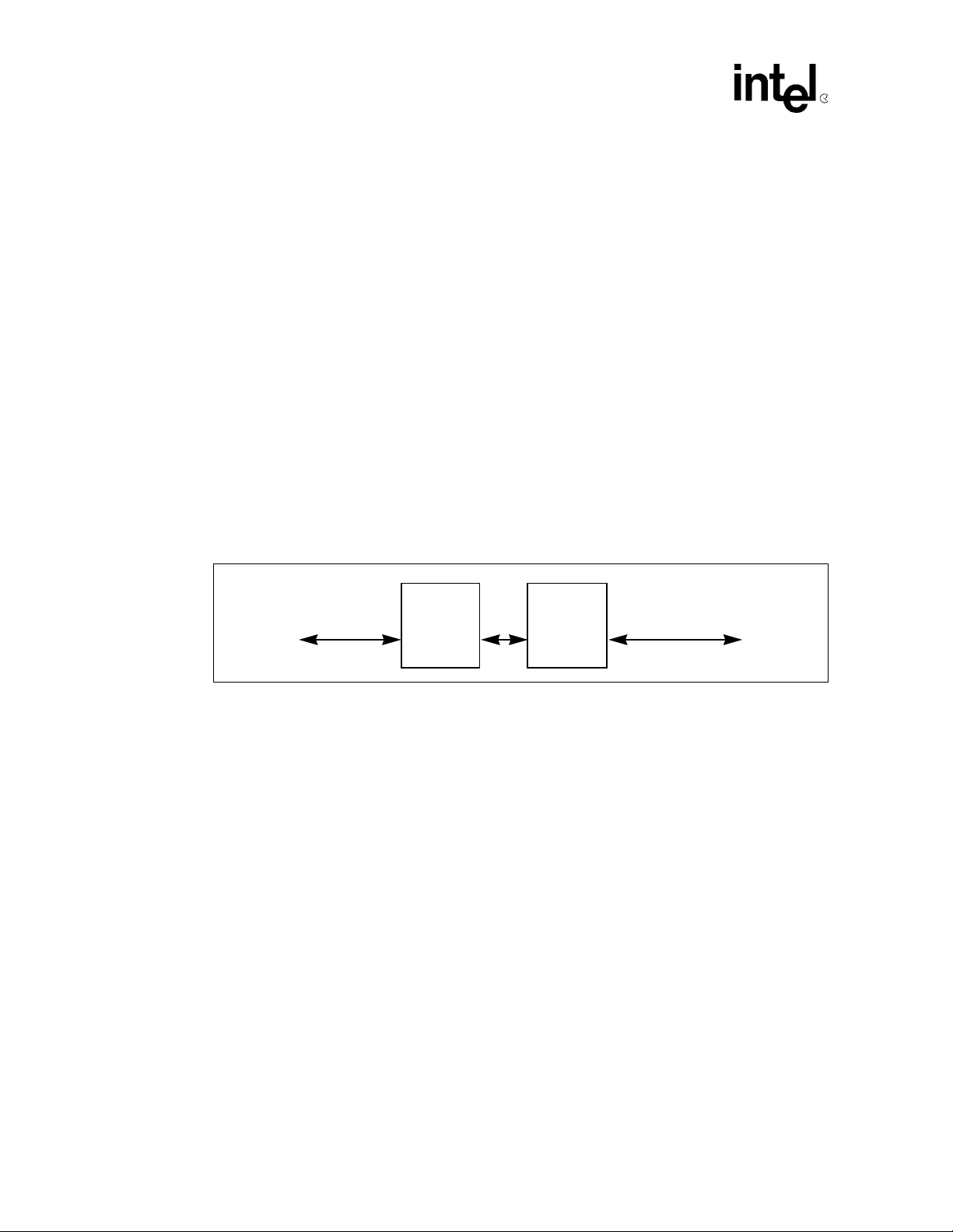
Figure 1. MII-Based PHY Design
MII Port
of
21143
The MII-based PHY design includes the following components:
MII-Based
PHY
Devices
Magnetics
• The MII-based PHY devices, which have a direct interface to the MII port of the 21143 with
dual-rate option (as specified in the MII specification) and a full interface to the 10/100 Mb/s
magnetics module.
• The magnetics module, which is based on transfo rmers and serial cho kes enabling the networ k
connection to the 100 Mb/s network (100BASE-TX or 100BASE-T4) and to the 10 Mb/s
network (10BASE-T).
1.4 SYM-Based PHY Block Diagram
Figure 2 is a block diagram of a 100BA SE-TX sing l e-con nect or net work connection using a SYM-
based PHY device with the 21143. For a 10 Mb/s network connection, the network can be
connected directly to the 21143 through filters and chokes.
10/100 Mb/s
Network
Module
6 Design Guide
Page 7
Intel® 21143 PCI/CardBus 10/100Mb/s Ethernet LAN Controller
SYM-based PHY devices are provided by GEC Plessey*, Quality Semiconductor*, and Micro
Linear*.
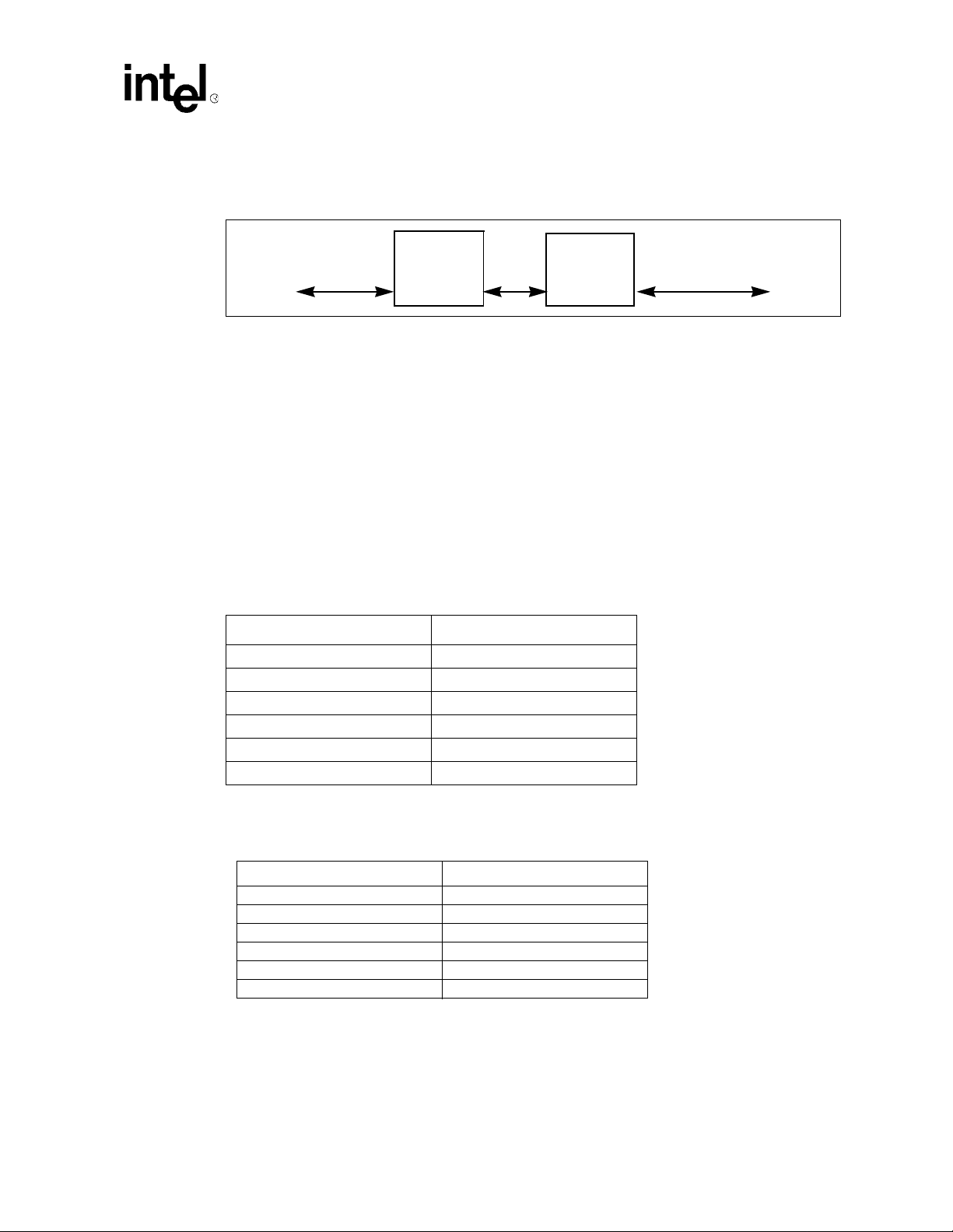
Figure 2. SYM-Based PHY Design
SYM Port
of
21143
The SYM-based PHY design includes the following component s :
• The SYM-based PHY devices, which have a direct interface to the SYM port of the 2114 3
with an interface to the 100 Mb/s magnetics module.
• The magnetics module, which is based on transformers and serial chokes enabling the network
connection to the 100 Mb/s-only network (100BASE-TX or 100BASE-T4).
2.0 21143 Ports
Table 2 lists the active AUI signals when the 21143 AUI port is selected.
Table 2. AUI Signals
Signal Pin Number
aui_cd– 138
aui_cd+ 137
aui_rd– 140
aui_rd+ 139
aui_td– 143
aui_td+ 142
SYM-Based
PHY
Devices
Magnetics
Module
100 Mb/s
Network
Table 3 lists the active twisted-pair signals when the 21143 10BASE-T port is selected.
Table 3. Twisted-Pair Signals
Signal Pin Number
tp_rd– 10
tp_rd+ 9
tp_td– 5
tp_td– – 4
tp_td+ 6
tp_td+ + 7
Table 4 lists the active MII signals when the 21143 MII port is selected.
Design Guide 7
Page 8
Intel® 21143 PCI/CardBus 10/100Mb/s Ethernet LAN Controller
Table 4. MII Signals
Signal Pin Number
mii_clsn 118
mii_crs 117
mii_dv 129
mii_mdc 134
mii_mdio 135
mii_rclk 128
mii_rx_err 127
mii_rxd <3:0> 133:130
mii_tclk 124
mii_txd<3:0> 119:122
mii_txen 123
Table 5 lists the active SYM signals when the 21143 SYM port is selected.
Table 5. SYM Signals
Signal Pin Number
sd 117
sel10_100 127
sym_rclk 128
sym_rxd<0> 130
sym_rxd<1> 131
sym_rxd<2> 132
sym_rxd<3> 133
sym_rxd<4> 118
sym_tclk 124
sym_txd<0> 122
sym_txd<1> 121
sym_txd<2> 120
sym_txd<3> 119
sym_txd<4> 123
8 Design Guide
Page 9

Intel® 21143 PCI/CardBus 10/100Mb/s Ethernet LAN Controller
3.0 Network Connection
The network connections of the 21143 can be used in 10BASE-T, AUI, MII, or SYM
configurations. Different methods are used to connect each port to the actual cable connector.
3.1 10BASE-T Twisted-Pair Network Port
Figure 3, Figure 4, and Figure 5 show the network connection design options for 10BASE-T type
implementations.
Figure 3 and Figure 4 show two ways of connecting the 10BASE-T network by using a standard
1:1 transformer module. This implementation type requires a swing compensator (to swing the
21143 output from 3.3 V to 5 V) to meet the standard requirements.
Figure 5 shows a direct connection to a 1: transformer module. This implementation type
provides the lowest component count for 10BASE-T. The filter and transformer components
minimize any potential electromagnetic interference and radio frequency interface problems.
Common-mode noise (when noise between two lines of the same polarity add rather than cancel)
can radiate energy from the twisted-pair interface. Also, significant common-mode power supply
noise can be generated on the board or adapter by other devices. Therefore, Intel recommends the
use of filter and transformer modules that incorporate common-mode chokes.
Table 8 and Table 10 list the part numbers for each implementation. Figure 3 shows the 10BASE-T
network connection with buffers. The required components for this configuration are as follows:
2
• Voltage swing compensator — 74ACT244
• Terminating and decoupling components
• Filter transformer and common-mode chokes
• RJ45 connector
Design Guide 9
Page 10

Intel® 21143 PCI/CardBus 10/100Mb/s Ethernet LAN Controller
Figure 3. 10BASE-T Network Connection with Buffers
21143
74ACT244
61.9
301
61.9
301
Ω
Ω
Ω
Ω
0.1 µF
tp_td+ 6
tp_td++ 7
Transmit
Path
tp_td- 5
tp_td-- 4
tp_rd- 9
Receive
Path
tp_rd- 10
8
6
4
2
GND
49.9
49.9
0.01 µF
12
14
16
18
Ω
Ω
806
Ω
3
TP Filters
and Chokes
78Z041
(SMD)
1
5
14
16
11
RJ45
8
1
2
6
9
3
6
GND
GND GND
LJ-05141.WMF
10 Design Guide
Page 11

Intel® 21143 PCI/CardBus 10/100Mb/s Ethernet LAN Controller
Figure 4 shows the 10BASE-T network connection without buffers. The required components for
this configuration are as follows:
• Terminating and decoupling components
• Transformer module (ratio of 1: for swing compensation)
2
• Filter transformer and common-mode chokes
• RJ45 connector
Figure 4. 10BASE-T Network Connection Without Buffers
21143
27
140
27
140
Ω
Ω
510 PRI SEC
Ω
Ω
49.9
Ω
Ω
49.9
0.01 µF
1: 2
0.1 µF
tp_td+ 6
tp_td++ 7
Transmit
Path
tp_td- 5
tp_td-- 4
tp_rd- 9
Receive
Path
tp_rd- 10
3
TP Filters
and Chokes
78Z041
(SMD)
1
5
14
16
11
RJ45
1
8
2
6
3
9
6
GND
GND
GND
LJ-05142.WMF
Design Guide 11
Page 12

Intel® 21143 PCI/CardBus 10/100Mb/s Ethernet LAN Controller
Figure 5 shows the minimum comp onent requiremen t fo r the 10B ASE-T netw ork c onnectio n. Thi s
implementation uses a filter transformer module with a 1: transformer on the transm it path to
compensate for the voltage swing. The required components for this configuration are as follows:
• Terminating and decoupling components
• Filter, transformer, and common-mode chokes
• RJ45 connector
Figure 5. Minimum Components Required for 10BASE-T
21143
2
tp_td+ 6
tp_td++ 7
Transmit
Path
tp_td- 5
tp_td-- 4
tp_rd- 9
Receive
Path
tp_rd- 10
27 Ω
140 Ω
27 Ω
140 Ω
GND
510 Ω
49.9 Ω
49.9 Ω
0.01 µF
TP Filters
and Chokes
78Z1122 or
FD22-114G
(SMD)
RJ45
1
2
3
6
GND
0.1 µF
GND
LJ-05143.WMF
3.2 100-Ready Designs
The 21143 can also be d esigned for s ystems that are “100-Ready.” The term “100-Ready” implies
a system that has a 10 Mb/s network that can easily be upgraded to become a 10/100 Mb/s network.
There are two methods for providing 100-Ready designs:
• Provide a connector for an internal optional daughtercard.
• Provide an MII connector for an external module that connects to the MII/SYM port.
These two methods are described in Table 6.
12 Design Guide
Page 13

Intel® 21143 PCI/CardBus 10/100Mb/s Ethernet LAN Controller
T a ble 6. Internal vs. External Design Features
Design Features
Internal optional daughtercard
External MII/SYM module
• Can be designed with an MII or any custom connector.
• Us er opens cabinet to install 100 Mb/s daughtercard.
• User connects module to external MII/SYM connector; user does
not have to open cabinet for installation.
3.2.1 Internal Optional Daughtercard
Figure 6 shows a block diagram of a 100-Ready design using a daughter card.
Figure 6. 10BASE-T 100-Ready Daughtercard Block Diagram
21143
PCI
Bus
MII
10BASE-T
Optional
MII
Daughtercard
Optional
AUI Coaxial
Transceivers
3.2.2 Description of 100-Ready Daughtercard Block Diagram
The blocks in the10BASE-T 100-Ready block diagram represent the following components:
• 21143 — A 21143 with all of the external components for operating the network connection
(reference parts, XTAL, and so on). The 21143 can use the PCI bus, and the MII/SYM,
10BASE-T, and AUI coaxial ports for communication.
• Optional MII/SYM daughtercard — A daughtercard with a 100 Mb/s or 10/100 Mb/s PHY
that interfaces with an MII connector or custom conn ector. The daughtercard can be designed
to use the same RJ45 connector.
• RJ45 — A network connection.
RJ45
Connector
AUI
Coaxial
Connector
LJ-05189.AI4
Design Guide 13
Page 14

Intel® 21143 PCI/CardBus 10/100Mb/s Ethernet LAN Controller
3.2.3 100-Ready External Module Design
Figure 7 shows a block diagram of a 100-Ready design using an external module.
Figure 7. 10BASE-T 100-Ready External Module Block Diagram
21143
PCI
Bus
MII/SYM
10BASE-T
Optional
AUI Coaxial
Transceivers
MII or
Custom
Connector
RJ45
Connector
AUI
Coaxial
Connector
MII or
Custom
Connector
10/100
PHY Layer
3.2.4 Description of 100-Ready Exte rnal Module Block Diagram
The blocks in the100-Ready external module block diagram represent the following components:
• 21143 — A 21143 with all of the external components for operating the network connection
(reference parts, XTAL, and so on). The 21143 can use the PCI bus, and the MII/SYM,
10BASE-T, and AUI coaxial ports for communication.
• Optional external MII/SYM daughtercard — A daughtercard wit h a 100 Mb/s or 10/100 Mb/s
PHY that interfaces with an MII connector or custom connector. The daughtercard uses the
magnetics to connect to the RJ45 connector.
• MII connector — An MII or custom connector that connects with the MII/SYM port of the 2 1 143.
RJ45
Connector
LJ-05188.AI4
• RJ45 — A network connection.
3.2.5 MII/SYM Pin Listing
Table 7 describes the MII/SYM pin multiplexing enabling the full flexibility for bot h netwo rk
connections options using the same internal connector for the MII-based or the SYM-based PHY
device (for detailed implementation notes, refer to the speci fic PH Y devi ce sectio n in t his document).
Table 7. MII/SYM Pinout (Sheet 1 of 2)
Pin Number MII Interface Function SYM Interface Function
117 mii_crs sd
118 mii_clsn sym_rxd<4>
119 mi_txd<3> sym_txd<3>
120 mi_txd<2> sym_txd<2>
121 mi_txd<1> sym_txd<1>
14 Design Guide
Page 15

Intel® 21143 PCI/CardBus 10/100Mb/s Ethernet LAN Controller
Table 7. MII/SYM Pinout (Sheet 2 of 2)
Pin Number MII Interface Function SYM Interface Function
122 mii_txd<0> sym_txd<0>
123 mii_txen sym_txd<4>
124 mii_tclk sym_tclk
127 mii_rx_err sel10_100
128 mii_rclk mii_rclk
129 mii_dv N.C.
130 mii_rxd<0> sym_rxd<0>
131 mii_rxd<1> sym_rxd<1>
132 mii_rxd<2> sym_rxd<2>
133 mii_rxd<3> sym_rxd<3>
134 mii_mdc N.C.
135 mii_mdio N.C.
3.3 AUI Network Port
The 21143 is fully compliant with the AUI standard. The AUI can interf ace with an external
medium-attachment unit (MAU) and connect to alternate media, such as 10BASE2 (ThinW ire) an d
10BASE5 (thickwire). Figure 8 and Figure 9 show the required connections.
Figure 8 shows the AUI 10BASE 5 networ k connecti on and the pi n conn ections bet ween the 2 1 14 3
and the isolation transformer. The required components for this configuration are as fo llows:
• Terminating and decoupling components
• Isolation transforme r
• AUI connector
Design Guide 15
Page 16

Intel® 21143 PCI/CardBus 10/100Mb/s Ethernet LAN Controller
Figure 8. AUI 10BASE5 Network and Pin Connections
21143
aui_rd+ 139
Receive
Path
aui_rd- 140
aui_cd+ 137
Collision
Path
aui_cd- 138
aui_td+ 142
Transmit
Path
aui_td- 143
0.01 F µ
GND
0.01 F µ
GND
18
47
GND
18
Isolation
Transformer
ST7032
10
Ω
40.2
Ω
40.2
9
13
Ω
40.2
40.2
Ω
12
Ω
Ω
511
Ω
Ω
16
22 pF
15
XFMR_RD+
7
XFMR_RD-
8
XFRM_CD+
4
XFRM_CD-
5
XFMR_TD+
1
XFMR_TD-
2
AUI
Connector
15
14
13
12
11
10
9
8
7
6
5
4
3
2
1
GND
40.2
40.2
Ω
Ω
GND
+12 V
0.22 F µ
GND
0.01 F µ
LJ-05144.WMF
16 Design Guide
Page 17

Intel® 21143 PCI/CardBus 10/100Mb/s Ethernet LAN Controller
Figure 9 shows the AUI 10BAS E2 network connection. In this configuration, the AU I is not
externally exposed. The required components for this configuration are as follows:
• Isolation transforme r
• Terminating and decoupling components
• DC-to-DC converter
• Coaxial transceiver and BNC connector
Figure 9. AUI 10BASE2 Network Connection
Ω
Ω
Ω
Ω
8
7
Isolation
Transformer
ST7032
10
9
13
12
16
15
-9 V
0.1 F
µ
XFMR_RD+
7
XFMR_RD-
8
XFRM_CD+
4
XFRM_CD-
5
XFMR_TD+
1
2
XFMR_TD-
1000 pF
40.2
40.2
511
511
511
511
Ω
Ω
GND
Ω
Ω
Ω
Ω
Coaxial
Transceiver
NE8392
Receive
Collision
Transmit
Ω
1 M
0.75 pF (1000 V)
1000 pF (1000 V)
21143
aui_rd+ 139
Ω
Ω
Ω
3
1
40.2
40.2
40.2
40.2
22 pF
511
Ω
2
Enable
dc-to-dc
Converter
80Z1209
4700 pF
+12 V
GND
0.01 F µ
GND
0.01 F µ
GND
18
47
GND
18
22 F
µ
Receive
Path
aui_rd- 140
aui_cd+ 137
Collision
Path
aui_cd- 138
aui_td+ 142
Transmit
Path
aui_td- 143
aui_bnc 100
0.1 F
µ
Note:
Refer to the vendor data sheet for the specific implementation of the coaxial transceiver (NE8392).
Coaxial
1 k
Ω
LJ-05145.WMF
In cases where 10BASE2 MAU is a module sep arate fro m the bo ard, MAU can b e implemente d on a
small add-in card. Ensure that the cable used to connect the board to MAU provides adequate shielding of
the AUI signals from external no ise. This MAU add -in card includes th e following co mponents:
• Transceiver chip and BNC connector
• DC-to-DC converter
• Discrete devices
Design Guide 17
Page 18

Intel® 21143 PCI/CardBus 10/100Mb/s Ethernet LAN Controller
3.4 Media-Specific Components
Table 8 lists the media-specific interface components for 10BASE-T access. Table 10 lists the
media-specific interface components for 10BASE2 and 10BASE5 access.
Table 8. 10BASE-T Media-Specific Components
Access Type Components Available Part Numbers
10BASE-T 74ACT244 driver 74ACT244 or 74FCT244
Filter and transformer module
Transformer filter and chokes
RJ45 wire jack connector —
1. Surface-mount devic e.
Pulse Engineering* PE65745
1
Valor*PT4096
Valor* ST7011
Halo* TD42-2006Q
1
1
Halo* TG42-2006W11
Pulse Engineering* PE65434
Valor* FL1012
1
Table 9. 10BASE2 and 10BASE5 Media-Specific Components
Access Type Components Available Part Numbers
10BASE2 DC-to-DC converter Fil Mag* 80Z1209DSND
Valor* ST7032
Pulse Engineering* PE65723
Isolation transformer
Coaxial transceiver National Semiconductor* DP8392C
Connector —
10BASE5 Isolation transformer
AUI connector —
1. Surface-mount devic e.
Valor* LT6032
Valor* ST6032/3
Halo* TD01-0756K
Halo* TG01-0756W
Valor* ST7032
Pulse Engineering* PE65723
Valor* LT6032
Valor* ST6032/3
Halo* TD01-0756K
Halo* TG01-0756W
1
1
1
1
1
1
1
1
1
1
1
1
18 Design Guide
Page 19
Intel® 21143 PCI/CardBus 10/100Mb/s Ethernet LAN Controller
4.0 21143 Requirements
This section provides information about the external component connections for the 21143, and
describes the following requirements:
• Unused JTAG port requirements
• Current reference and capacitor input
• Crystal connection or crystal oscillator connection for the serial clock connection
4.1 Unused JTAG Port Requirements
Table 10 describes the 21143 signal pin requirements if you are not using the JTAG port.
Table 10. Pin Requirements When Not Using the JTAG Port
Leave the Following JTAG Pins Open Pull the Following JTAG Pin Up or Down
tms (pin 1) tck (pin 120)
tdi (pin 2)
tdo (pin 4)
4.2 Current Reference and Capacitor Input Requirements
Table 11 describes the current reference and capacitor input requirements for the 21143, and
Figure 10 shows the external component connections.
Table 11. Current Reference and Capacitor Inputs
Pin Name Pin Number Function Connect This Pin...
iref 108
vcap_h 110 Capacitor input Through a 0.022
Current reference input for the analog
phase-locked loop (PLL)
Through a 2.4 k
Ω resistor to ground
µF capacitor to ground
Design Guide 19
Page 20

Intel® 21143 PCI/CardBus 10/100Mb/s Ethernet LAN Controller
Figure 10. 21143 External Component Connect ions
®
Intel
Ethernet Controller
Crystal
Connection
21143
xtal1
xtal2
106
105
10 k
Ω
100
Ω
82 pF
120 pF
GND
20-MHz
Crystal
Crystal
Oscillator
Connection
Current
Reference
Connection
xtal1
xtal2
iref
vcap_h
106
107
108
110
20-MHz Input Clock
No Connection
2.4 k
Ω
GND
0.022 µF
GND
4.3 Crystal and Crystal Oscillator Connections
Figure 10 shows two serial clock connections; select either the crystal connection or the crystal
oscillator connection. According to the IEEE 802.3 standard, a 20 MHz crystal is required. The
crystal frequency must not vary by more than 100 parts per million (PPM), or 0.01%. Place the
crystal as close as possible to the 21143.
Because the frequency of crystals from different vendors can vary , test the crystals in the actual circuit. It
may be necessary to vary the tuning of the surrounding components. However, after the capacitors have
been tuned for the specific crystal, the design does not need to be altered on a board-by-board basis.
B0033-01
The 21143 also supports a crystal oscillator (Figure 10). This configuration requires no external
component and xtal2 should be left open.This is useful for applications with multiple network connections.
Table 12 lists the crystal specifications.
T able 12. Crystal Specifications
Specification Value Units
Crystal frequency 20.000 MHz
Frequency tolerance
±50 PPM
Load capacitance 50 pF
Frequency stability
Maximum effective series resistance 40 Ohms (
±30 PPM
Ω)
Test condition drive level 100 µW
20 Design Guide
Page 21

Intel® 21143 PCI/CardBus 10/100Mb/s Ethernet LAN Controller
5.0 Signal Routing and Placement
The Ethernet circuitry should be kept free of interference from unrelated signal traces. Routing for
other signals must be kept away from the space surrounding the grouped Ethernet components. Place
the Ethernet circuitry at the perimeter of the board, as close as possible to the network connector.
The onchip crystal oscillator requires an external crystal and discrete components. For stable and
noise-free operation, place the crystal and discrete components as close as possible to the 21143,
keeping the etch length as short as possible. Do not route any noisy signals in this area.
The PCI pin ordering is fully compatible with the PCI specification recommendation and can be
easily routed within the specified etch limits of the PCI signals. This includes shared signal lengths
of up to 3.8 cm (1.5 in) and the clock signal length of 6.41 cm (2.5 in).
Keep all signal paths short and route them as directly as possible.
Systems using 10BASE-T nodes can be co nnected by cable s up to 1 00m (328 ft.). As a result, signals
that reach the board can be noisy and low in amplitude. To minimize corrupting this data, route these
signals, by most direct path, fr om the n etwork co nnector and throu gh the magnetics co upler to the 21143.
The length of this path should not exceed 8 cm (3 in) for the active AUI signals. The MII/SYM
interface operates at 25 MHz (or 2.5 MHz). All routing of the MII/SYM signals to the MII/SYM device
should be as short as possible and should not have significant differences of lengths and characteristics
within signal groups. Examples of signal groups include mii_rxd<4:0> and mii_txd<4:0>.
Note: The routing of these signals should be done with caution. The preferred routing of these signals is
in the external routing layers of the board . The MII/SYM device should be located between the
21143 and the magnetics port.
5.1 Ground and Power Planes
Up to four types of power signals require handling when imp l ementing a design with t he 21143:
• Gnd is adapter ground.
• Vcc (+5 V from PCI) drives the external components (boot ROM and Ethernet addres s ROM).
• Vdd (+3.3 V) drives the 21143.
• Vee (-9 V output) power from the DC-to-DC converter if the coaxial network connection is
implemented. For information specific to the -9 V power supply, refer to the transceiver used
to drive the coaxial network connection.
Intel recommends that at least two power planes be kept on the PCB: Vcc and Gnd. The Vdd
power plane (+3.3 V) can be implemented either by a cut in the Vcc power plane, or by a power
island under the 21143 on one of the signal routing layers.
Intel recommends that decoupling capacitors should be connected to all power supplies. These
capacitors should be placed as close as possible to the power pins of the chips. The recommended
values are as follows: 0.1 µF, 0.01 µF, 10 µF (tantalum), and 47 µF (tantalum).
For better noise-testing immunity, separate all power planes between the network connectors and
the transformer from the logic and analog power planes of the adapter for the 10BASE-T,
10BASE2, 100BASE-T4, and 100BASE-TX connecti on s.
Design Guide 21
Page 22

Intel® 21143 PCI/CardBus 10/100Mb/s Ethernet LAN Controller
Intel also recommends that the conn ector’s shield of the adapter should be connected to the PC chassis.
5.1.1 3.3 V Power Supply
The 21143 operates with a po wer supply of 3.3 V. At least eight decoupling capacitors are
recommen ded and should contain the following values:
• Three each at 0.1 µF
• Three each at 0.01 µF
• One each at 10 µF (tantalum)
• One each at 47 µF (tantalum)
5.2 LED Status Signals
The LED connection requires a serial resistor that is connected to ground . This resi stor v alue s hould
be calculated according to the type of LED used. A typical 2 mA LED requires a 750
implementations using the boot ROM, the LED current should not exceed 2 mA. For LED indication
and programming information, refer to the CS R15 definition in the 21143 PCI /Car dBus 10/100Mb/s
Ethernet LAN Controller Hardware Reference Manual.
Ω resistor. For
The 21143 requires LED time-stretching logic for a visible indication of the activity signal.
Figure 11 shows how to implement this circuit.
Figure 11. LED Time-Stretcher Circuit
100 kΩ
Active Low
Active High
1N14B
1N14B
100 kΩ
+5 V
22 nF
22 nF
74
HCT132
74
HCT132
750 Ω
+5 V
750 Ω
LJ-04061.AI4
22 Design Guide
Page 23

Intel® 21143 PCI/CardBus 10/100Mb/s Ethernet LAN Controller
6.0 Design Considerations
This section provides information to aid the user in designi ng Ethernet and Fas t Ethernet capabili ties
onto a motherboard. In addition, it also includes design considerations for FCC compl iance.
6.1 Designing the Ethernet Corner on Motherboards
This subsection provides a list of routing suggestions and a list of component placement suggestions.
The following list contains routing recommendations:
• Minimize the length of high-frequency signals.
• Route differential signal pairs together.
• Minimize the use of vias for high-frequency signals.
The following list contains component placement recommendations.
• Refer to the PCI Local Bus Specification, Revision 2.1 for the placement of the 21143 with
relation to the PCI bus.
• Place the 21143 as close to the PHY device as possible.
• Place the PHY device as close to the filters and magnetics as possible.
• Place the filters and magnetics as close to the RJ45 connector as possible.
6.2 Suggestions for FCC Compliance
Product designs and their associated applications are unique. Therefore, the designer must consider
the total system or module implementation when determining a product d esign for FCC compliance.
The following information is provided as suggestions only to aid the designer in meeting FCC
regulations.
6.2.1 Suggestions for Quiet Ground and Power Planes
For quiet ground and power planes, consider the following suggestions:
• Isolate power plane for PLL stability and noise isolation of audio digital-analog converters and
amplifiers.
• Partition ground planes to isolate the I/O from common system noise. Do not route any etch
across an isolated or partitioned ground plane.
Note: Ground plane splits can affect a signal’s return path back to its source. If the signal return path is
along the ground plane underneath the signal etch, any interruption in the ground plane increases
the return path loop area, which in turn, increases its ability to radiate.
• Add common-mode chokes to the design at the output of the isolation transformer to isolate
the I/O from common system noise.
• Place high-speed signals between power and ground planes to reduce board-level radiation.
The following books are recommended as additional references:
• Fundamentals of Electromagnetic Capability, by William G. Duff
Design Guide 23
Page 24

Intel® 21143 PCI/CardBus 10/100Mb/s Ethernet LAN Controller
• Engineering Electromagnetic Capability, by V. Pras ad Kodal i
6.2.2 Suggestions for Routing
For routing information, consider the follo w ing sug ges tio ns :
• Never route any etch (power or ground) across a partition or void because the signal loses its
return-path integrity and contaminates the isolated plane.
• Avoid placing oscillators, phase-locked loops, and other clock-type devices near I/O connectors.
• Route all critical signals (for example; clocks, video output) directly in the etch and avoid, if
possible, using vias (signal paths routed between planes in an etch board).
Note: Critical signals should be prioritized from the fastest to the slowest with respect to frequency and
rise time. The fastest critical signals should be routed first.
24 Design Guide
 Loading...