

Page 1

Intel® Embedded Development
Board 1-N450 and
Intel® Embedded Development
Board 1-D510
User Guide
June 2011
Revision 003
Document Number: 324421
Page 2

INFORMATION IN THIS DOCUMENT IS PROVIDED IN CONNECTION WITH INTEL® PRODUCTS. NO LICENSE, EXPRESS OR
IMPLIED, BY ESTOPPEL OR OTHERWISE, TO ANY INTELLECTUAL PROPERTY RIGHTS IS GRANTED BY THIS DOCUMENT. EXCEPT
AS PROVIDED IN INTEL‟S TERMS AND CONDITIONS OF SALE FOR SUCH PRODUCT S, INTEL ASSUMES NO LIABILITY
WHATSOEVER, AND INTEL DISCLAIMS ANY EXPRESS OR IMPLIED WARRANTY, RELATING TO SALE AND/OR USE OF INTEL
PRODUCTS INCLUDING LIABILITY OR WARRANTIES RELATING TO FITNESS FOR A PARTICULAR PURPOSE, MERCHANTABILITY,
OR INFRINGEMENT OF ANY PATENT, COPYRIGHT OR OTHER INTELLECTUAL PROPERTY RIGHT. Intel products are not intended for
use in medical, life saving, or life sustaining applications.
Intel may make changes to specifications and product descriptions at any time, without notice.
Designers must not rely on the absence or characteristics of any features or instructions marked “reserved” or “undefined.” Intel
reserves these for future definition and shall have no responsibility whatsoever for conflicts or incompatibilities arising f rom future
changes to them.
The Intel® Embedded Development Board 1-N450 and Intel® Embedded Development Board 1-D510 may contain design defects
or errors known as errata which may cause the product to deviate from published specifications. Current character ized errata are
available on request.
Contact your local Intel sales office or your distributor to obtain the latest specifications and before placing your product order.
I2C is a two-wire communications bus/protocol developed by Philips. SMBus is a subset of the I2C bus/protocol and was
developed by Intel. Implementations of the I2C bus/protocol may require licenses from various entities, including Philips
Electronics N.V. and North American Philips Corporation.
Alert on LAN is a result of the Intel-IBM Advanced Manageability Alliance and a trademark of IBM.
Intel, Atom and the Intel logo are trademarks or registered trademarks of Intel Corporation or its subsidiaries in the United
States and other countries.
*Other names and brands may be claimed as the property of others.
Copyright © 2011, Intel Corporation. All rights reserved.
2 324421/ User Guide
Page 3

Contents
1 Introduction ...................................................................................................... 7
1.1 Content Overview ................................................................................... 7
1.2 Terminology ........................................................................................... 8
1.3 Technical Support ................................................................................... 9
1.4 Product Literature .................................................................................. 10
1.5 Related Documents ................................................................................ 10
1.6 Notes, Cautions and Warnings ................................................................. 11
2 Development Kit Overview ................................................................................. 12
2.1 Intel® Atom™ Processor N450 and D510 Compute Modules ........................ 12
2.1.1 General Features ...................................................................... 13
2.1.2 Connector Features ................................................................... 14
2.2 Mini-ITX Carrier ..................................................................................... 15
2.2.1 Features .................................................................................. 15
2.3 Software Overview ................................................................................. 17
2.3.1 OS Support .............................................................................. 17
2.3.2 UEFI Firmware ......................................................................... 18
2.3.3 EC Firmware ............................................................................ 18
2.4 Before You Begin ................................................................................... 18
3 OS Installations ................................................................................................ 19
3.1 Driver Overview ..................................................................................... 19
3.1.1 Network Drivers ....................................................................... 19
3.1.2 Graphics Drivers ....................................................................... 19
3.1.3 Chipset Drivers ......................................................................... 19
3.2 Windows 7 ............................................................................................ 19
3.2.1 Requirements ........................................................................... 19
3.2.2 Installation Instructions ............................................................. 20
3.3 Windows XP .......................................................................................... 20
3.3.1 Requirements ........................................................................... 20
3.3.2 Installation Instructions ............................................................. 21
3.4 MeeGo .................................................................................................. 22
3.4.1 Requirements ........................................................................... 22
3.4.2 OS Installation Instructions ........................................................ 22
4 Platform Firmware Update ................................................................................. 24
4.1 BIOS Update ......................................................................................... 24
4.1.1 Windows.................................................................................. 24
4.1.2 MS- DOS ................................................................................. 24
4.2 Management Controller Update ................................................................ 25
4.2.1 Requirements ........................................................................... 25
4.2.2 Installation Steps ..................................................................... 25
5 Obtaining Support ............................................................................................ 29
6 Hardware Overview ........................................................................................... 30
6.1 Certified Devices .................................................................................... 30
324421/ User Guide 3
Page 4

6.1.1 MINI-PCI Express ..................................................................... 30
6.2 Mini-ITX Carrier Overview ....................................................................... 30
6.2.1 Back-panel .............................................................................. 30
6.2.2 Internal Interfaces .................................................................... 31
6.2.3 Fan Headers ............................................................................ 32
6.2.4 USB5 ...................................................................................... 33
6.2.5 Serial Ports .............................................................................. 33
6.2.6 LPT Port .................................................................................. 34
6.2.7 Lane Setup .............................................................................. 34
6.2.8 Management Header ................................................................. 36
7 BIOS Overview ................................................................................................. 38
7.1 BIOS Main Screen .................................................................................. 38
7.1.1 Platform Version Information ..................................................... 39
7.2 Advanced Configuration .......................................................................... 39
7.2.1 Serial Port Console Redirection ................................................... 40
7.3 Chipset Configuration Screen .................................................................. 41
7.3.1 South Bridge Configuration ........................................................ 42
8 Inserting/Removing the Module .......................................................................... 44
8.1 Removal ............................................................................................... 44
8.2 Insertion ............................................................................................... 44
9 Cable Solutions ................................................................................................ 46
9.1 EC Serial Console Cable .......................................................................... 46
9.1.1 Requirements ........................................................................... 46
9.1.2 Wiring Instructions ................................................................... 46
9.2 Serial Port Cable (COM1 – COM4) ............................................................ 47
9.2.1 Requirements ........................................................................... 47
9.2.2 Wiring Instructions ................................................................... 47
10 Regulatory Compliance ...................................................................................... 48
Figures
Figure 1 Compute Module (without heat-sink) ...................................................... 13
Figure 2 Carrier with Compute Module Installed .................................................... 17
Figure 3 Terminal Window Settings ..................................................................... 26
Figure 4 Boot Manager Screen ............................................................................ 27
Figure 5 Boot Manager Interface Menu in HyperTerminal ....................................... 27
Figure 6 Xmodem Send File ............................................................................... 28
Figure 7 Mini-ITX Back-Panel ............................................................................. 30
Figure 8 Front Panel Header (J2103) ................................................................... 31
Figure 9 Fan Header .......................................................................................... 32
Figure 10 USB Port 5 Header .............................................................................. 33
Figure 11 Serial Port Header .............................................................................. 33
Figure 12 LPT Header ........................................................................................ 34
Figure 13 Lane Configuration Header .................................................................. 35
Figure 14 Management Header ........................................................................... 36
Figure 15 LC1 Headers and Connectors ............................................................... 37
Figure 16 BIOS Main Screen ............................................................................... 38
Figure 17 Platform Information Screen ................................................................ 39
4 324421/ User Guide
Page 5

Tables
Figure 18 Advanced Configuration Screen ............................................................ 40
Figure 19 Serial Port Console Redirection ............................................................. 41
Figure 20 Chipset Configuration Screen ............................................................... 42
Figure 21 South Bridge Configuration Screen ....................................................... 42
Figure 22 Compute Module Insertion Step#1 ....................................................... 45
Figure 23 Compute Module Insertion Step#2 ....................................................... 45
Table 1 Intel® Literature Centers ........................................................................ 10
Table 2 Related Documents ................................................................................ 10
Table 3 Power Front Panel LED States ................................................................. 31
Table 4 Front Panel Power Switch Behavior .......................................................... 32
Table 5 Management Port Wiring ........................................................................ 46
Table 6 Serial Port Wiring .................................................................................. 47
324421/ User Guide 5
Page 6

Revision History
Document
Number
Revision
Number
Description
Revision Date
324421
001
Initial release.
September 2010
324421
002
Added Fan header information (For use with D510
module).
March 2011
324421
003
Removed cable options from chapter 2.
June 2011
§
6 324421/ User Guide
Page 7

Introduction
1 Introduction
This document describes the Intel® Embedded Development Board features and
functions. The platform is a modular solution consisting of a compute module and a
Mini-ITX carrier.
Two Compute Modules and a single carrier board are available for this platform. The
carrier will be populated with one of the following configurations:
Intel® Atom™ Processor N450 with Intel® 82801HM I/O Controller Compute
Module with Intel® Compute Module Mini-ITX Carrier
Intel® Atom™ Processor D510 with Intel® 82801HM I/O Controller with
Intel® Compute Module Mini-ITX Carrier
This manual is written for OEMs, system evaluators, and embedded system
developers. This document describes all jumpers, headers, LED functions, and their
location of the development board along with subsystem features. This manual
assumes basic familiarity with the fundamental concepts involved with installing and
configuring hardware for a personal computer system.
Read this document in its entirety prior to applying power to the motherboard. Intel
recommends having both the schematic and board present while reading this
document.
1.1 Content Overview
Chapter 1, ”Introduction”: Explains the content in this document, key terminology,
where to get product literature and related documents
Chapter 2, “Development Kit Overview” : Explains the high-level features of the
development kit.
Chapter 3, “OS Installations”: Explains how to install Windows and Linux-based OS.
Chapter 4, “Platform Firmware Update”: Explains how to update the Compute Module
and the Compute Module Embedded Controller Firmware.
Chapter 5, “Obtaining Support”: Explains how to obtain support.
Chapter 6, “Hardware Overview”: Explains the Hardware in detail.
Chapter 7 , “Bios Overview”: Gives details on BIOS.
Chapter 8, “Inserting/Removing Modules”: Gives details on how to insert/remove the
compute module into/from carrier.
Chapter 9, “Cable Solutions”: Gives details on building cables for the module.
Chapter 10, “Regulatory and Compliance Information”
324421/ User Guide 7
Page 8
1.2 Terminology
Term
Description
ACPI
Advanced Configuration Power Interface
BGA
Ball Grid Array
Compute Module
A compute module and CPUDIMM are synonyms
CPUDIMM
A compute module based on the Intel Compute Module Interface
Definition.
DDR
Double Data Rate
DMA
Direct Memory Access
EC
Embedded Controller
EFI
Extensible Firmware Interface
FAE
Field Application Engineer
FSB
Front Side Bus
FWH
Firmware Hub
GPIO
General Purpose Input Output
IDE
Integrated Device Electronics
IEGD
Intel® Embedded Graphics Driver
IMVP
Intel® Mobile Voltage Positioning
Intel® HD Audio
Intel® High Definition Audio
ITP
In-Target Probe
JEDEC
Joint Electron Device Engineering Council
KBC
Keyboard Controller
LAN
Local Area Network
LED
Light Emitting Diode
LPC
Low Pin Count
LVDS
Low Voltage Differential Signaling
OS
Operating System
PATA
Parallel AT Attachment
Introduction
8 324421/ User Guide
Page 9
Term
Description
PC
Personal Computer
PCB
Printed Circuit Board
PCIe*
PCI Express*
PGA
Pin Grid Array
PLL
Phase Lock Loop
RTC
Real Time Clock
SIO
Super I/O (Input Output)
SMC
System Management Controller
SO-DIMM
Small Outline Dual In-line Memory Module
SPI
Serial Peripheral Interface
TPM
Trusted Platform Module
TSSOP
Thin Shrink Small Outline Package
UART
Universal Asynchronous Receiver/Transmitter (COM/Serial Port)
UEFI
Unified Extensible Framework Infrastructure
USB
Universal Serial Bus
VGA
Video Graphics Array
VID
Voltage Identification
VR
Voltage Regulator
VTT
Voltage Termination
XDP
eXtended Debug Port
Introduction
1.3 Technical Support
Support Services for your hardware and software are provided through the secure
Intel® Embedded Developers Support Web site at http://edc.intel.com/Support.
324421/ User Guide 9
Page 10
1.4 Product Literature
U.S and Canada
1-800-548-4725
U.S. (from overseas)
708-296-9333
Europe (U.K.)
44(0)1793-431155
Germany
44(0)1793-421333
France
44(0)1793-421777
Japan (fax only)
81(0)120-47-88-32
Document
Document
No./Location
Processor and I/O Controller -Related Documents
Intel® Atom™ Processors 400 and 500 Series with the Intel®
82801HM I/O Controller Platform Design Guide
Contact your local Intel
representative for the latest
revision
Intel® Atom™ Processors 400 and 500 Series with the Intel®
82801HM I/O Controller Platform Schematics
Intel® Atom™ Processors 400 and 500 Series with the Intel®
82801HM I/O Controller Mechanical and Cadence / OrCad
Symbol Files
Intel® Atom™ Processor N400 Series Datasheet Volumes I & II
Intel® Atom™ Processor D400 and D500 Series Datasheet
Volumes I & II
Intel® Atom™ Processor N400 Series – Sightings Report (SR)
Intel® Atom™ Processor D400 and D500 Series– Sightings
Report (SR)
Intel® Atom™ Processors 400 and 500 Series with the Intel®
82801HM I/O Controller Platform Datasheet Addendum
Intel® I/O Controller Hub 8 (ICH8) Family Datasheet
You can order product literature from the following Intel® literature centers.
Table 1 Intel® Literature Centers
Product literature and information can also be found on the following sites:
Intel® Developer Center: http://developer.intel.com/design/index.htm
Intel® Embedded Design Center: http://edc.intel.com/
1.5 Related Documents
Introduction
Table 2 is a partial list of the available collateral. For the complete list, contact your
local Intel representative.
Table 2 Related Documents
10 324421/ User Guide
Page 11
Document
Document
No./Location
Intel® I/O Controller Hub (Intel® ICH8M) Specification Update
Processor and I/O Controller -Related Documents
Aptio 4.x Whitepaper
http://www.ami.com/aptio
Note
Calls attention to important information
Caution
Cautions are included to help you avoid damaging hardware and losing data
Warnings
Warnings indicated conditions, which if not observed, can cause personal
injury
Introduction
1.6 Notes, Cautions and Warnings
§
324421/ User Guide 11
Page 12

Development Kit Overview
2 Development Kit Overview
The development kit is shipped with the following:
Platform:
o Intel® Atom™ N450 or D510 Compute Module
o Mini-ITX carrier board
External Power Supply Brick
2.1 Intel® Atom™ Processor N450 and D510
Compute Modules
The Intel® Atom™ Processor N450 and D510 Compute Modules are a new class of
platforms which are part of a broader family of compute modules. The Compute
Module family is a set of interchangeable compute modules and reference platforms.
The platforms are based on a new module design which emphasizes minimal PCB
footprint, while maintaining scalability across a broad range of price, performance and
power consumption vectors. Each module implements a JEDEC 244-pin DIMM
connector to provide unmatched I/O capability in a small form-factor. This high
density connector architecture allows each module in the family to support all of the
I/O required to support a range of embedded computing requirements.
The first modules in the family are based on the Intel® Atom™ Processor N450 and
D510 with the Intel® 82801HM I/O Hub (ICH8M).
12 324421/ User Guide
Page 13
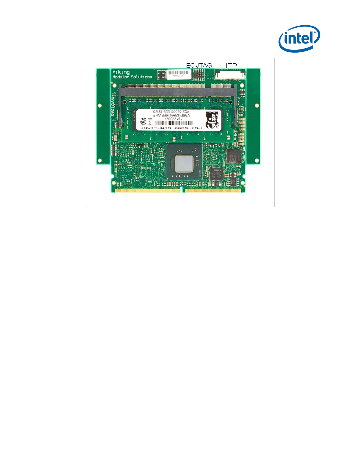
Development Kit Overview
Figure 1 Compute Module (without heat-sink)
2.1.1 General Features
2.1.1.1 Processor
The module is available with either an Intel® Atom™ processor N450 or Intel® Atom™
processor D510.
2.1.1.2 Chipset
The compute Module is built around the Intel® 82801HM I/O Controller.
2.1.1.3 Discrete LAN Adapter
The module has a discrete Intel® 82574 LAN Adapter with side-band support.
2.1.1.4 Integrated LAN adapter
The compute module implements the Intel® 82567 LAN Physical Interface for the
integrated LAN adapter in the Intel® 82801HM I/O Controller.
2.1.1.5 24-pin SFF ITP/XDP JTAG Connector
A 24-pin SFF ITP/XDP Processor Debug Connector is provided that allows for 3rd party
debuggers to be used for debugging for custom BIOS development.
324421/ User Guide 13
Page 14

2.1.1.6 Renesas Embedded Controller
The µController is responsible for the power management of the module, and provides
a serial console interface to allow for basic management of the compute module.
2.1.1.7 Memory
The module supports either a 1 or 2 GB DDR2-667 SODIMM.
2.1.2 Connector Features
2.1.2.1 PCI Express*
The module provides 4 PCI Express lanes. The PCI Express lanes can be configured as
follows:
One PCI Express* X4
One PCI Express* X2 and two PCI Express* X1
Development Kit Overview
Four PCI Express* X1
2.1.2.2 SATA-300
The module provides 3 discrete SATA ports.
2.1.2.3 USB 2.0
The module provides 6 USB 2.0 ports.
2.1.2.4 LAN
The module provides two 1 Gigabit Ethernet MDI interfaces.
2.1.2.5 DISPLAY
The module supports both VGA and Single Channel LVDS.
2.1.2.6 LPC
The module provides an LPC interface.
2.1.2.7 Management Interface
The module provides a:
Serial Console to the Module Management controller.
I2C Interface to read Carrier Configuration Data and other management
sensors on the carrier.
14 324421/ User Guide
Page 15

2
1
Development Kit Overview
Power Management signals to support ACPI Power Management of the carrier.
2.1.2.8 Power
12V and 3.3V power
2.2 Mini-ITX Carrier
The carrier platform, as shown in Figure 2, provides all the required interfaces to the
capabilities exposed by the Compute Module. In addition, the carrier provides
additional interfaces that are typically common across multiple compute module
definitions (e.g. Super I/O). The carrier provided as part of this development kit
provides a super-set of the interfaces required by the Intel® Atom™ Processor N450
and D510 Compute Modules.
2.2.1 Features
2.2.1.1 PCI Express*
The carrier can be configured to support the following combination:
1 PCI Express* X1 and Mini-PCI Express
1 PCI Express* X2 and Mini-PCI Express
1 PCI Express* X4
2.2.1.2 USB 2.0
The carrier supports 4 external rear-panel over-current protected USB ports and 1
unprotected USB port on an internal header.
2.2.1.3 LAN
The carrier supports 2 X 10/100/1000 Ethernet ports.
2.2.1.4 SATA-300
The carrier supports 6 SATA1 connectors.
2.2.1.5 Flexible Display Interfaces
The carrier provides the following display interfaces on rear-panel connectors:
VGA
Display Port
Only SATA 0-2 are available with the Atom based Compute Module
324421/ User Guide 15
Page 16

Development Kit Overview
3
2
3
HDMI
In addition a 50-pin LVDS connector is provided on the carrier. Panel specific cables
are required for each display supported.
2.2.1.6 Legacy PS2 Keyboard and Mouse
A legacy keyboard and mouse rear-panel socket is provided.
2.2.1.7 Serial Interfaces
Four RS232 Serial Interfaces are provided on internal headers.
2.2.1.8 Parallel Port
1 Parallel port is provided on an internal header
Display Port is not available with Atom based Compute Module
HDMI is not available with an Atom Based Compute Module
16 324421/ User Guide
Page 17
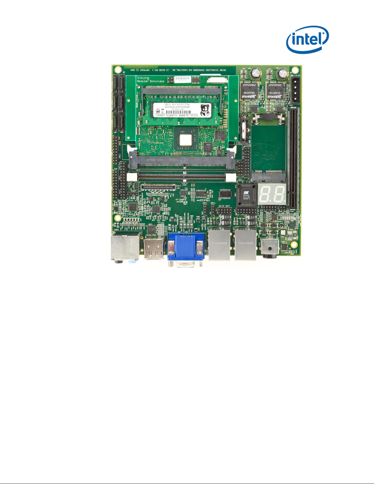
Development Kit Overview
Figure 2 Carrier with Compute Module Installed
2.2.1.9 LPC
A 20-pin extension LPC header is provided on the ITX.
2.2.1.10 RTC Battery
Battery-backed real time clock.
2.2.1.11 Port 80 Decode
Support down on Mini-ITX with 2 seven segment displays.
2.3 Software Overview
2.3.1 OS Support
The following Operating Systems have been tested:
324421/ User Guide 17
Page 18

Windows XP* Service Pack 3
Windows 2007*
Moblin* (Linux based)
Fedora* (Linux based)
2.3.2 UEFI Firmware
This development kit ships with a pre-boot EFI firmware pre-installed. This industry
standard EFI firmware runs most standard operating systems, including Microsoft
Windows XP*, Microsoft Windows 7*, Microsoft Windows XP Embedded*, Linux, and
others.
The following features of the EFI firmware are enabled in the development board:
DDR2 SDRAM detection, configuration, and initialization
Intel® Atom™ Processor N450 and D510 with the Intel® 82801HM I/O
Controller Hub configuration
PCI/PCI Express* device enumeration and configuration
Integrated video configuration and initialization
Super I/O configuration
CPU microcode update
Development Kit Overview
2.3.3 EC Firmware
The Compute Module includes an Embedded Microcontroller that is designed to
manage the overall module. All power management and system compatibility
management is handled through the Embedded Controller. At times it may be required
to upgrade the EC firmware. Refer to Section 4.2 for this process.
2.4 Before You Begin
The following additional hardware may be necessary to successfully set up and
operate the development board.
VGA Monitor: Any standard VGA monitor may be used. The setup instructions in this
chapter assume the use of a standard VGA monitor, TV, or flat panel monitor.
Keyboard: The development board can support either a PS/2 or USB style keyboard.
Mouse: The development board can support either a PS/2 or USB style mouse.
§
18 324421/ User Guide
Page 19

OS Installations
3 OS Installations
The following section provides an overview for installing some of the more common
variants of operating systems. Additional OS Live images and instructions are posted
at http://bit.ly/devboard.
3.1 Driver Overview
Drivers for the various operating systems are either included by default by the OS
vendor (depending on release cycle), are available from Intel‟s support site,
http://downloadcenter.intel.com or at http://bit.ly/devboard.
3.1.1 Network Drivers
http://downloadcenter.intel.com/SearchResult.aspx?lang=eng&ProductFamily=Ethern
et+Components&ProductLine=Ethernet+Controllers&ProductProduct=Intel%c2%ae+8
2574+Gigabit+Ethernet+Controller&ProdId=3023&LineId=976&FamilyId=2280
3.1.2 Graphics Drivers
The Intel® Atom™ Processor N450 and D510 graphics engine is the Intel® Graphics
Media Accelerator 3150. The latest drivers can be found at:
http://support.intel.com/support/graphics/intelgma3150
3.1.3 Chipset Drivers
The Intel® Atom™ Processor N450 and D510 compute module uses the Intel®
82801HM I/O Hub. The drivers for this chipset are part of the Intel® 900 Series family
of chipsets. The drivers can be found at:
http://support.intel.com/support/chipsets/sb/CS-025753.htm
3.2 Windows 7
3.2.1 Requirements
Windows 7 Installation Disk
Windows Driver and Tools Release-Package
324421/ User Guide 19
Page 20

3.2.2 Installation Instructions
3.2.2.1 Base OS
1. Install the Base OS following the instructions as outlined by the Windows 7
Installer.
2. After installation is complete copy the Release-Package-X-Windows.zip to your
local hard-drive and extract.
3.2.2.2 Chipset Drivers
Windows does not have the default drivers for the 82801HM I/O Controller Hub
(ICH8M) as part of its installation package.
1. Download the latest chipset drivers from the link provided in the Driver
Overview Section.
2. Execute the downloaded file
OS Installations
3. Follow the onscreen instructions
3.2.2.3 LAN Drivers
The LAN Driver package supports both LAN Devices on the Compute Module.
1. If you have installed a version before, please uninstall first.
2. Download drivers from the link provided in the Driver Overview section
3. Follow the instructions provided with the LAN Driver Package
The system may require a reboot. It is suggested at this time to carry out the reboot.
3.2.2.4 Display Drivers
Windows 7 does not include the latest display drivers.
1. Download drivers from the link provided in the Driver Overview section
2. Follow the instructions provided with the Display Driver Package
The system may require a reboot. It is suggested at this time to carry out the reboot.
3.3 Windows XP
3.3.1 Requirements
Windows XP SP3 Installation Disk
20 324421/ User Guide
Page 21

WARNING: The current display drivers will blank your screen after an initial OS
Reboot. Please follow these instructions carefully!!
OS Installations
Windows Driver and Tools Release-Package
3.3.2 Installation Instructions
3.3.2.1 Base OS
1. Install the Base OS following the instructions as outlined by the Windows XP
Installer Screens.
2. After installation is complete, copy the driver release package on to your local
hard-drive and extract.
3.3.2.2 Chipset Drivers
Windows does not have the default drivers for the 82801HM I/O Controller Hub
(ICH8M) as part of its installation package.
1. Download the latest chipset drivers from the link provided in the Driver
Overview Section.
2. Execute the downloaded file
3. Follow the onscreen instructions
3.3.2.3 LAN Drivers
The LAN Driver package supports both LAN Devices on the Compute Module.
1. If you have installed a version before, please uninstall first.
2. Download drivers from the link in the Driver Overview section above.
The system may require a reboot. It is suggested at this time to carry out the reboot.
3.3.2.4 Display Drivers
Windows XP does not include the latest display drivers.
1. Download drivers from the link provided in the Driver Overview section
2. Navigate to the extracted location and run setup. Note: If you have installed a
previous version you MUST uninstall first, otherwise the changes will not take
place.
3. Install the drivers
324421/ User Guide 21
Page 22

OS Installations
4. Reboot
When the system reboots with the provided drivers, the monitor and screen will be
black. By default, windows will be at the login prompt waiting for a password.
1) Enter your password. If you make a mistake, you will need to do a hard-reset as
you will not be able to see the screen
a) The display will become visible after you logon.
2) Change the Display Settings as follows:
a) Right Click on the icon of the Intel Graphics Media Accelerator Driver in the
task bar
b) Select “Graphics Properties”
c) Change Operating Mode to: “Single Display”
d) Change Display Selection (Primary Device) to: “Monitor”
3) Press Apply and then Ok
4) Reboot
The next time system reboots, you should have a visible display. If the screen is still
black please repeat the above steps.
3.3.2.5 Audio Drivers
The LC1 Carrier card has a HD Audio Subsystem based on a Conexant AD1989B.
1. The audio driver package is located under <ReleasePackage>\Mini-
ITX\Windows\Audio
2. Extract the archive AD1884A XP Flat Generic Driver.zip
3. Navigate to the extracted location and run setup.
4. Install the drivers
5. Reboot
3.4 MeeGo
3.4.1 Requirements
Software
Download MeeGo for Netbooks from http://meego.com
3.4.2 OS Installation Instructions
1. Insert the CD/DVD into the CD/DVD drive.
22 324421/ User Guide
Page 23

OS Installations
2. You will be presented with 3 options
3. Go to “Install to disk” and press <enter>
4. Follow Installation instructions as provided.
§
324421/ User Guide 23
Page 24

Platform Firmware Update
4 Platform Firmware Update
4.1 BIOS Update
To update the EFI image in DOS to a newer release, use the EFI binary image and a
BIOS update utility. One utility that can be used is the AFUDOS BIOS update utility,
also referred to as a BIOS flash utility, with a command line interface for MS-DOS.
This utility is available through AMI and can be accessed here.
4.1.1 Windows
Copy the AFUWIN.EXE executable file to any storage location accessible by the host
system and then run AFUWIN in a Windows DOS environment command prompt.
Basic Usage:
AFUWIN <BIOSROMIMAGE>.ROM /P (XXXX is the BIOS version to be flashed)
o Program main BIOS image, reset CMOS to defaults
Your keyboard and mouse will be suspended during the burn process.
You can alternatively use the GUI version (see AMI documentation)
4.1.2 MS- DOS
Copy the AFUDOS.EXE executable file to any storage location accessible by the host
system and then run AFUDOS in a DOS environment command prompt.
Basic Usage:
AFUDOS <BIOSROMIMAGE>.ROM /P /C (XXXX is the BIOS version to be
flashed)
o Program main BIOS image, reset CMOS to defaults
AFUDOS ROMFILE.ROM /P /B /N /C
o Program main BIOS image & bootblock image
o Reset CMOS and NVRAM to defaults
Note: Afudos.exe comes in two versions, one for legacy BIOS update and one
for EFI BIOS update. These two versions are not cross compatible. Using afudos.exe
for legacy BIOS to update an EFI BIOS will generate an error message such as
24 324421/ User Guide
Page 25

Platform Firmware Update
memory error. Please make sure to download the latest afudos.exe for EFI BIOS to
update the evaluation board. AMI„s EFI BIOS is called AMI Aptio.
4.2 Management Controller Update
The management controller firmware can be updated through the management
interface on the Mini-ITX.
4.2.1 Requirements
Appropriate Serial Cable
Windows Machine with a Terminal Client supporting XModem
The latest Management Controller Firmware
4.2.2 Installation Steps
1. Configure the Terminal Client as shown in Figure 3
2. Connect the serial Port cable to the serial port on the PC and to J2101 on the
mini-itx.
3. Make sure that the terminal client is in the connect state
4. Hit the reset switch on the carrier or recycle power
5. When the Embedded Controller boots, you will see a display as shown in
Figure 4.
6. Within 3 seconds press any key and you will see a dialog as shown in Figure 5.
7. Select Option 1 if you want to reflash firmware
8. When prompted to start Xmodem, select Transfer->Send File from the
Terminal Client Menu as shown in Figure 6.
9. Enter the file that you want to download and press send.
10. After the firmware has been downloaded, press any key and the menu will
reappear.
11. Select 3 to boot the Embedded Controller or recycle power
324421/ User Guide 25
Page 26

Platform Firmware Update
Figure 3 Terminal Window Settings
26 324421/ User Guide
Page 27

Platform Firmware Update
Figure 4 Boot Manager Screen
Figure 5 Boot Manager Interface Menu in HyperTerminal
324421/ User Guide 27
Page 28

Platform Firmware Update
Figure 6 Xmodem Send File
§
28 324421/ User Guide
Page 29

Obtaining Support
5 Obtaining Support
When requesting support, you may be asked for specific information about the
system. This information is both available on the boards themselves or through BIOS.
To obtain the information through BIOS, power-cycle the system while holding the
<del> key. When the BIOS screen appears, select the Platform Configuration option.
Displayed will include the following information:
BIOS Firmware Version
EC Firmware Version
Atom Module Serial Number
Mini-ITX Serial Number.
§
324421/ User Guide 29
Page 30

6 Hardware Overview
6.1 Certified Devices
The following devices have been certified to function correctly with the system.
6.1.1 MINI-PCI Express
Intel® Mini-PCI Express WIFI card Model#: 4965AGN
6.2 Mini-ITX Carrier Overview
6.2.1 Back-panel
Hardware Overview
Figure 7 Mini-ITX Back-Panel
6.2.1.1 Audio Sub-System
The 5.1 Audio sub-system has a non-standard mapping on the connector
1. Standard Audio (Head Phone Out/Line out) is on Black
2. For 5.1 Surround sound use Black , Green (Back Surround) and Pink (Center
Channel / Sub-woofer)
3. MIC IN – Orange (Yellow in diagram above)
30 324421/ User Guide
Page 31

1 2
3 4
5 6
7 8
9 10
VCC
VCC
GND
RESET
N/C
Front Panel Sleep LED
Front Panel Green LED (Pwr)
Front Panel Button
GND
N/C
LED State
Description
ACPI State
Off
Sleeping or Power Off
S1, S3, S5
Steady
Running
S0
Blinking
Running/Message Waiting
Currently Not Supported
Hardware Overview
6.2.2 Internal Interfaces
6.2.2.1 Front Panel Header
Voltages supplied to the front panel connector such as VCC (+3.3 V) are not
over-current protected and should connect only to devices inside the computer‟s
chassis. Do not use these connectors to power devices external to the computer‟s
chassis. A fault in the load presented by an external device could cause damage to the
computer, the interconnecting cable, and the external device itself. It is strongly
recommended that power provided to the external connector shall always implement
over-current protection. Figure 8 gives the pin-out definition for the Front-Panel
Header.
Figure 8 Front Panel Header (J2103)
6.2.2.1.1 Sleep /Message Waiting Activity Light
This feature is currently not supported in release.
6.2.2.1.2 Power / Message Waiting Light
Connecting pins 1 and 2 to a single, front panel mounted LED provides power on/off,
sleep and message waiting indication. The states of the LED are shown below
Table 3 Power Front Panel LED States
Currently Message Waiting functionality is not supported, but may be included
as part of an EC and BIOS firmware release in the future.
324421/ User Guide 31
Page 32

System State
Action
ACPI State
G3Soft/S5/S3
Held for less than 4 seconds and
released
Final State S0
S0
Held for less than 4 seconds and
released
Based on OS Configuration
Any
Held for more than 4 seconds and
released
S5, G3Soft
1
2
3
4
GND
VCC
(12V)
Fan In
Fan Out
6.2.2.1.3 Reset Switch
Supporting of the reset function requires connecting pins 7 and 8 to a momentarycontact switch that is normally open. When the switch is closed power to the Compute
Module will be reset, causing the power manager (EC) to recycle.
6.2.2.1.4 Power Switch
The implementation of the Power Switch provides slightly different behavior
from a traditional power switch.
Supporting the power on/off function requires connecting pins 5 and 6 to a
momentary-contact switch that is normally open. When the switch is held according to
the actions in Table 4, the system can be powered on and off.
Table 4 Front Panel Power Switch Behavior
Hardware Overview
6.2.3 Fan Headers
There are two Fan headers on the board. The D510 Compute module has a heat sink
with a fan; its fan header should be connected to one of the fan headers ( Fan 1 or
Fan 2). The compute module‟s fan header should be connected with the black GND
wire at pin 1; pin 4 will be left unconnected. Pin 1 is farthest from the silk screened
“Fan 1” or “Fan 2” words on the board.
Figure 9 Fan Header
32 324421/ User Guide
Page 33

1
2
3
4
+5V
D-
D+
GND
1 2
3 4
5 6
7 8
9 10
DCD
RX
TX
DTR
GND
DSR
RTS
CTS
RI
N/C
Hardware Overview
6.2.4 USB5
The USB 5 port does not have over-current protection. It is recommended that it
be always connected to an external powered USB Hub that provides appropriate overcurrent protection. Figure 10 gives the pin-out for USB 5.
6.2.5 Serial Ports
Figure 10 USB Port 5 Header
1. The pin-outs for Serial Ports COM1 – COM4 are shown in Figure 11.
2. Pin 1 is identified with a bold square.
Figure 11 Serial Port Header
324421/ User Guide 33
Page 34

6.2.6 LPT Port
Figure 12 shows the pin-out for the LPT Header.
Hardware Overview
Figure 12 LPT Header
6.2.7 Lane Setup
The Mini-ITX Carrier is designed to provide flexibility in the configuration of PCIe,
SATA and USB Ports. Figure 13 shows the pin-out for the lane setup header.
34 324421/ User Guide
Page 35

1 2
3 4
5 6
7 8
9 10
PCI Express Config
N/C
GND
GND
GND
GND
N/C
N/C
SATA Configuration
USB5 Configuration
Hardware Overview
Figure 13 Lane Configuration Header
6.2.7.1 PCIe Lane Configuration
Pins 1-2 will indicate to the Embedded Controller on the Compute Module how to
configure the Intel® 82801HM I/O Controller PCIe* controller and the carrier. The
jumper configuration can be over-ridden through BIOS, as described later in this
document.
6.2.7.2 SATA Lane Configuration
6.2.7.3 USB 5 Lane Configuration
When No Jumper is placed on pins 1-2, the lanes are configured as follows:
Lane 0 and 1 are connected to the PCIeX16 connector
Lane 2 is connected to the Mini-PCIe Port
Lane 3 is connected to the Flash-DIMM Connector J1201
When a jumper is placed on pins 1-2, the lanes are configured as follows:
Lane 2 and 3 are connected to the PCIeX16 to create a PCIeX4 configuration
Pins 5-6 configure the destination of SATA Port 0.
When No Jumper is placed, SATA Port 0 is connected to SATA-0 on the carrier.
When a jumper is placed, SATA Port 0 is connected to the FLASH-DIMM Connector
J1201.
Pin 7-8 configures the destination for USB-5.
When No Jumper is placed, USB-5 is available on header J1202.
When a jumper is placed, USB-5 is available on the FLASH-DIMM Connector J1201.
324421/ User Guide 35
Page 36

6.2.8 Management Header
1 2
3 4
5 6
7 8
9 10
Mgmt GPIO 0
Mgmt GPIO 1
GND
GND
GND
GND
11 12
13 14
Mgmt GPIO 2
Mgmt GPIO 3
Mgmt GPIO 4
EC-TX
EC-RX
GND
Mgmt SMB_CLK
Mgmt SMB_DAT
Figure 14 defines the pin-out for the Management Header, J2101. Please see section
on creating an appropriate serial cable for connecting to a RS232 Terminal Client (e.g.
Windows Terminal Client).
Hardware Overview
6.2.8.1 Serial Interface
6.2.8.2 Enable/Disable LVDS
Figure 14 Management Header
The serial interface is level shifted on the carrier to the correct voltage
levels for RS232.
The Management Controller currently provides visibility for debugging purposes,
programming BIOS and LAN Firmware through the serial Interface. Later in this
document (Platform Configuration), the process is described in detail.
Place a jumper GPIO1 (pin 3 and 4) of J2101 to enable LVDS.
36 324421/ User Guide
Page 37

Hardware Overview
Figure 15 LC1 Headers and Connectors
§
324421/ User Guide 37
Page 38

7 BIOS Overview
The BIOS is UEFI based, using AMI‟s Aptio 4.x implementation. The following section
describes some salient features of BIOS.
Certain BIOS settings changes require that the platform be cold booted. In
these circumstances, you will be required to restart the system by either pressing the
power button, or by issuing a command on the Management Serial Console Interface.
7.1 BIOS Main Screen
Figure 16 shows the main screen of BIOS. The version of BIOS installed is determined
by looking at the Project Version and Build Date.
It is recommended that you set the correct date and time on initial boot.
BIOS Overview
Figure 16 BIOS Main Screen
The compute module does not have an onboard battery to backup the real-
time clock. Removing the module from the carrier, will result in the real-time clock not
reflecting the current date and time.
38 324421/ User Guide
Page 39

BIOS Overview
7.1.1 Platform Version Information
From the Main Screen, the platform Information can be obtained, by selecting the
“Platform Information” entry. Figure 17 shows the Platform Information Screen. The
information may be required by support.
Figure 17 Platform Information Screen
7.2 Advanced Configuration
Figure 18 shows the advanced configuration screen. Via this screen, it is possible to
configure advanced platform options.
324421/ User Guide 39
Page 40

Figure 18 Advanced Configuration Screen
BIOS Overview
It is not recommended that these settings be changed, unless you have a clear
understanding of the impact of the setting or you are directed to do so by support.
One exception is Serial Port Console redirection.
7.2.1 Serial Port Console Redirection
In certain application and operating systems it is desirable to interact with the
platform through a serial console. Ports 1 and 2 of the Super I/O on the carrier can be
utilized for this purpose. Figure 19 shows the available settings.
40 324421/ User Guide
Page 41

BIOS Overview
Figure 19 Serial Port Console Redirection
7.3 Chipset Configuration Screen
Figure 20 shows the chipset configuration screen. Through this screen it is possible to
configure the behavior of the I/O subsystems of the platform, including graphics,
memory, LAN, USB, PCIe*, etc.
One particular feature (not present in other platform implementations) is the ability to
configure the PCIe* Lane width. The configuration screen can be accessed by selecting
“South Bridge Configuration”
324421/ User Guide 41
Page 42

Figure 20 Chipset Configuration Screen
BIOS Overview
7.3.1 South Bridge Configuration
Figure 21 shows the South Bridge Configuration Screen. Two settings are of particular
importance as the impact how the PCIe* subsystem is configured on the compute
module and carrier.
Figure 21 South Bridge Configuration Screen
42 324421/ User Guide
Page 43

BIOS Overview
As described earlier in the guide, it is possible to use a jumper on the carrier to set
the desired lane configuration. By default, the jumper is used by the Embedded
Controller to determine the lane setup. However, the jumper configuration can be
overridden through BIOS by changing the PCIe Lane Config Option.
The PCIe Lane Config option provides the following options:
4X PCIeX1
1X PCIeX2 , 2X PCIeX1
1X PCIeX4
Jumper
The PCIe Lane Config Text field will provide the configuration selected (e.g. in the
screen shot, the Embedded Controller is using the jumper settings to determine the
lane setup which is “1X PCIeX2 & 2X PCIeX1”
§
324421/ User Guide 43
Page 44

Inserting/Removing the Module
8 Inserting/Removing the
Module
Please ensure that all necessary electrostatic precautions are taken when
inserting or removing a module from the system. In addition, all power must be
removed from the system during this process.
The compute module is screwed down to the carrier board to ensure that the module
does not move during shipping. If for, any reason, the compute module needs to be
removed from the carrier, the following guidelines need to be followed:
8.1 Removal
1. Ensure that all necessary ESD steps have been taken.
2. Ensure the system is disconnected from wall power.
3. Remove the 2 screws holding the module in place.
4. Unlatch the module from the DIMM connector by simultaneously pushing on
the white clips on the DIMM connector.
8.2 Insertion
Figure 22 and Figure 23 show the required finger positions when inserting a module.
The module is inserted fully when the clips on the DIMM connector close. It is
recommend the spaces be inserted and the module secured to the carrier.
44 324421/ User Guide
Page 45

Inserting/Removing the Module
Figure 22 Compute Module Insertion Step#1
Figure 23 Compute Module Insertion Step#2
§
324421/ User Guide 45
Page 46

9 Cable Solutions
2X14
Signal
DB9
1
--- 2
--- 3
--- 4
--- 5
--- 6
--- 7
--- 8
--- 9
--- 10
GND
5
11
TX
2
12
--- 13
RX 3 14
---
9.1 EC Serial Console Cable
A console cable may be provided in the box. If not, the following instructions should
be followed to create an appropriate cable.
9.1.1 Requirements
The following hardware is required:
1. Female DB9 Connector
2. Cable with at least 3 wires
3. 3 single female header connectors
Cable Solutions
9.1.2 Wiring Instructions
Connect the 3 wires to the following pins on the DB9 Connector:
Table 5 Management Port Wiring
46 324421/ User Guide
Page 47

Table 6 Serial Port Wiring
2X5 pin
Signal Name
DB9 pin
1
DCD
1
2
DSR
6 3 RxD#
2 4 RTS
7 5 TxD#
3 6 CTS
8 7 DTR
4 8 RI
9
9
Ground
5
10
---
Cable Solutions
9.2 Serial Port Cable (COM1 – COM4)
COM Ports 1 and 2, and Com Ports 3 and 4 are implemented on 2X10 headers. The
following is the map of each of the serial ports to a DB9 connector.
9.2.1 Requirements
The following hardware is required:
1. 2X Female DB9 Connector
2. Cable with at least 9 wires (or 18 wires if 2 COM Ports are being wired)
3. 2X10 header
9.2.2 Wiring Instructions
The header for each COM port is wired as follows (note for COM Port 2 and 4 pin 1
would be pin 11 on a 2X10 header):
§
324421/ User Guide 47
Page 48

10 Regulatory Compliance
USA
These boards were tested and must be installed in a host chassis.
This equipment has been tested and found to comply with the limits for a Class B
digital device, pursuant to part 15 of the FCC Rules. These limits are designed to
provide reasonable protection against harmful interference in a residential installation.
This equipment generates, uses and can radiate radio frequency energy and, if not
installed and used in accordance with the instructions, may cause harmful interference
to radio communications. However, there is no guarantee that interference will not
occur in a particular installation. If this equipment does cause harmful interference to
radio or television reception, which can be determined by turning the equipment off
and on, the user is encouraged to try to correct the interference by one or more of the
following measures:
Reorient or relocate the receiving antenna.
Increase the separation between the equipment and receiver.
Connect the equipment into an outlet on a circuit different from that to which
the receiver is connected.
Consult the dealer or an experienced radio/TV technician for help.
Regulatory Compliance
Modifications not expressly approved by the manufacturer could void the user's
authority to operate the equipment under FCC rules.
Canada
This Class B digital apparatus meets all requirements of the Canadian InterferenceCausing Equipment Regulations.
Cet appareil numérique de la classe B respecte toutes les exigences du Réglement sur
le matériel brouilleur du Canada.
Japan
この装置は、クラスA情報技術装置です。この装置を家庭環境で使用すると電波妨害を引
き起こすことがあります。この場合には使用者が適切な対策を講ずるよう要求されるこ
とがあります。 VCCI-B
48 324421/ User Guide
Page 49

Regulatory Compliance
European Union
European Community (CE) Mark of Conformity Statement
This product is in conformity with the protection requirements of EC Council Directive
2004/108/EC on the approximation of the laws of the Member States relating to
electromagnetic compatibility. The boards must be installed in a host chassis to
remain in compliance. Intel cannot accept responsibility for any failure to satisfy the
protection requirements resulting from a non-recommended modification of the
product.
When installed in a host chassis, this product has been tested and found to comply
with the limits for Class B Information Technology Equipment according to CISPR
22/European EN 55022. The limits for Class B equipment were derived for typical
residential environments to provide reasonable protection against interference with
licensed communication devices.
Properly shielded and grounded cables, connectors, and a host chassis must be used
in order to reduce the potential for causing interference to radio and TV
communications and to other electrical or electronic equipment.
This product bears the CE Mark complying with the EMC (EN55022 & EN 55024) and
Low Voltage Directives.
This product complies with the Low Voltage Directive 2006/95/EC through compliance
with EN 60950-1, Ed. 2.
A signed copy of the Declaration of Conformity is on file and is available from Intel.
Dieses Gerät erfüllt die Bedingungen der EN 55022 Klasse B.
European Power Notices
IMPORTANT: For 230 VAC operation, be sure to use a harmonized grounded 3-
conductor cord, rated 8 Amp minimum, with a suitable cord for connection to the
equipment and terminating in an IEC approved plug for proper connection to the
branch circuit.
ATTENTION: Aucun composant situé à l'intérieur du boîtier ne peut être manipulé par
l'utilisateur. Pour toute intervention, vous devez faire appel à un technicien spécialisé.
IMPORTANT: Pour un fonctionnement à 230 VAC, vous devez utiliser un câble
conducteur à 3 fils avec mise à la terre, 8 Ampères minimum, doté d'un cordon
approprié pour la connexion à l'appareil et se terminant par une prise conforme à la
norme IEC, pour le raccordement au réseau électrique.
324421/ User Guide 49
Page 50

Regulatory Compliance
ATTENTION: Para operacion a 230 VAC, ten quidado usarse un alambre armoniziado &
conectado con la tierra, potencia nominal de 8 Amp, con un cordon propiamente
terminada para conexion al equipaje y el otro cordon que esta terminando en una
clavija de conexion IEC visto bueno para conexion al circuito gajo.
VORSICHT: In der Stromversorgungsabdeckung befindliche Teile können nicht vom
Benutzer gewartet werden. Die Wartung ist ausschließlich qualifiziertem
Wartungspersonal zu überlassen.
WICHTIG: Beim Betrieb mit 230 VAC ist unbedingt ein harmonisiertes, geerdetes Kabel
mit 3 Leitern und minimalem Nennwert von 8 Ampere zusammen mit einem
passenden Kabel für den Geräteanschluß zu verwenden, das in einem IECgenehmigten Stecker für den ordnungsgemaßen Anschluß an den Abzweigkreis endet.
European Regulatory Information
The CE Marking has been applied to this product to demonstrate compliance with the
following European Directives:
2004/108/EC -- for electromagnetic compatibility
2006/95/EC -- for safety
Warnungen
Das Wort 'Warnung' erscheint immer dann, wenn Verletzungsgefahr für Personen oder
ein Beschädigungsrisiko für Geräte besteht. Leisten Sie in einem solchen Fall den
Anweisungen Folge.
Elektrostatische Entladung
Eine elektrostatische Entladung vom Betriebspersonal an den Computer kann das
Gerät beschädigen. Sie müssen beim Anbringen eines Kabels Vorsichtsmaßnahmen
hinsichtlich elektrostatischer Entladung treffen:
Fassen Sie sämtliche Verbindungen ausschließlich am Plastikgehäuse oder der
Steckerabschirmung an. Kommen Sie beim Einstecken niemals mit den
Metallteilen innerhalb des Steckers in Berührung.
Bevor Sie die Schnittstellenkabel einstecken, müssen Sie das Gerät 'erden'.
Kann Ihre Stromversorgung ein- und ausgeschaltet werden, müssen Sie den
Schalter während dieses Vorgangs in der 'Aus'-Position belassen.
Vor dem Anbringen von Kabeln müssen Sie sich selbst ebenfalls 'erden', um
eine eventuelle, an Ihnen haftende statische Aufladung abzuleiten. Dazu
berühren Sie einfach die hintere Abdeckung des Gerätegehäuses einige
Sekunden lang.
Vergessen Sie niemals, sich vor dem Umgang mit gedruckten Leiterplatten
oder deren Komponenten sorgfältig zu 'erden'.
Diese Vorsichtsmaßnahmen verringern das Beschädigungsrisiko für das Gerät durch
elektrostatische Entladungen deutlich.
Interaktion mit anderen Geräten
Sollen andere Komponenten, einschließlich Kabel, zwischen dem Gerät und dem Anschlußpunkt
an einen digitalen Circuit angeschlossen werden, müssen alle anderen Komponenten den
folgenden Richtlinien entsprechen:
50 324421/ User Guide
Page 51

Regulatory Compliance
1. Die allgemeinen Übertragungseigenschaften aller anderen Komponenten dürfen keine
materiellen Auswirkungen auf die elektrischen Bedingungen der Komponenten untereinander
und zu dem speziellen digitalen Circuit hervorrufen.
2. Alle anderen Komponenten dürfen lediglich folgende Geräte umfassen:
Zugelassene Geräte (siehe Hinweis) zum Erstellen einer Verbindung zwischen dem
Hinweis: Derartige Geräte wurden möglicherweise nur für den eingeschränkten Einsatz
zugelassen.
Ventilation im Installationsumfeld
Es muß stets für ausreichende Luftzirkulation um das Gerät gesorgt sein.
VARNING: Endast Intel kvalificerade tekniker har tillstånd att utföra underhållsarbete på enheten.
VARNING: Vid åskväder ska du aldrig ansluta eller koppla ur kablar eller arbeta med installation,
underhåll eller omkonfigurering av utrustningen.
VARNING: För att undvika elolycksfall:
Gerät und einem bestimmten digitalen Circuit; und
Nätkabeln måste anslutas till ett rätt kopplat jordat eluttag.
Även annan utrustning som ska anslutas till den här produkten måste anslutas till jordat
uttag.
FARE: Kun Intel kvalifiserte teknikere er berettiget til å utføre servicearbeid på enheten.
FARE: For å unngå elektrisk støt må ikke kabler kobles til eller fra. Du må heller ikke foreta
installering, vedlikehold eller rekonfigurering av dette produktet i tordenvær.
FARE: For å unngå elektrisk støt:
Nettkabelen må være plugget i en korrekt koblet og jordet stikkontakt.
Alt utstyr som er koblet til dette produktet må være plugget i en korrekt koblet stikkontakt.
FARE: Slå av nettspenningen og trekk nettkabelen ut av stikkkontakten før du kobler signalkabler
til eller fra.
FARE! Undgå elektrisk stød:
Produktet må hverken installeres, vedligeholdes eller omkonfigureres I tordenvejr. Det samme
gælder for tilslutning eller afmontering af kabler.
FARE! Undgå elektrisk stød:
Netledningen skall tilsluttes en korrekt installeret stikkontakt med forbindelse til jord.
Sørg for korrekt installation af stikkontakterne, både til produktet og til det udstyr, det
tilsluttes.
324421/ User Guide 51
Page 52

Regulatory Compliance
FARE! Før signalkablerne tilsluttes eller afmonteres: Sluk, for strømmen, og træk netledningen ud
af stikkontakten.
GEVAAR: Alleen technische personen van Intel hebben de bevoegheid om dit produkt te
onderhouden.
GEVAAR: Om het gevaar voor elektrische schokken te vermijden, mag u geen kabels aansluiten of
loskoppelen en dit product niet installeren, onderhouden of opnieuw instellen tijdens een onweer.
GEVAAR: Om elektrische schokken te vermijden:
moet het netsnoer aangesloten zijn op een correct bedraad en geaard stopcontact.
moeten alle machines waarmee dit product zal worden verbonden ook op correcte bedraden
stopeontacten zijn aangesloten.
GEVAAR: Zet de netschakelaar op O (Uit) en trek de stekker uit het stopcontact vooraleer u
signaalkabels los- of vastkoppelt.
VORSICHT: Aus Sicherheitsgründen bei Gewitter an diesem Gerät keine Kabel angeschließen
oder lösen. Ferner keine Installations-, Wartungs oder Rekonfigurationsarbeiten durchführen.
VORSICHT: Aus Sicherneitsgründen
Gerät nur an eine Schutzkontaktsteckdose mit ordnungsgemäß geerdetem Schutzkontakt
anschließen.
Alle angeschlossenen Geräte ebenfalls an Schutzkontaktstckdosen mit ordnungsgemäß
geerdetem Schutzkontakt anschließen.
VORSICHT: Aus Sicherheitsgründen is der Netzstecker zu ziehen, bevor Signalkabel angeschlossen
oder aufgetrennt werden.
DANGER: Le service pour l’entretien de cette unité est seulement autorisé aux techniciens
qualifiés de Intel.
DANGER: Pour éviter tout risque de choc électrique, ne manipulez aucun câble et n’effectuez
aucune opération d’installation, d’entretien ou de reconfiguration de ce produit pendant
l’occurrence d’un orage.
DANGER: Pout éviter tout risque de choc électrique:
Le cordon d’alimentation doit être branché sur une prise d’alimentation correctement câblée
et mise en terre.
D’autre part, tout le matériel connecté à ce produit doit également être branché sur des prises
d’alimentation correctement câblées et mises en terre.
AVERTISSEMENT: Débranchez la prise du contrôleur hors tension et du cordon d’alimentation
avant de connecter ou de déconnecter les câbles d’interface.
PERICOLO: La manutenzione dell'unità deve essere consentita solo a tecnici qualificati per Intel
52 324421/ User Guide
Page 53

Regulatory Compliance
PERICOLO: Per evitare scosse elettriche, non collegare o scollegare cavi o effettuare installazioni,
riconfigurazioni o manutenzione di quest prodotto durante un temporale.
PERICOLO: Per evitare scosse elettriche:
Il cavo di alimentazione deve essere collegato a una presa munita di terra di sicurezza e
propriamente cablata.
Tutte le unità esterne di questo prodotto, devono essere collegate a prese munite di terra di
sicurezza e propriamente cablate.
PERICOLO: Spegnere l’unità e scollegare il cavo di alimentazione dalla resa, prima di collegare o
scollegare i cavi segnali.
PERIGO: Soménte os técnicos qualificados Intel astão autorizados à prestarem serviços nesta
unidade.
PERIGO: Para evitar possiveis choques elétricos, favor não liguar ou desliguar cabos, não instale,
repare ou reconfigure este produto durante tempestade.
PERIGO: Para evitar choques eléctricos:
O cabo de alimentação deve estar ligado à uma tomada de corrente corretamente instalada,
com ligaçao terra.
Todo o equipamento ligado à este produto deve estar também ligado à tomadas corretamente
instaladas.
PELIGRO: Solamente los técnicos calificados de Intel están autorizados para reparar la unidad.
CUIDADO: Desligue a corrente e retire o cabo de corrente elétrica da tomada, antes de ligar ou
desligar os cabos de sinal.
PELIGRO: Para evitar la posibilidad de descargas, no conecte o desconecte ningún cable, ni
realice ninguna instalación, servicio de mantenimiento o reconfiguración de este producto
durante una tormenta eléctrica.
PELIGRO: Para evitar el peligro de descargas:
Los cables de alimentación deben estar conectados a receptáculos con conexión a tierra y
cableado adecuados.
Todos los equipos a los que se conecte este producto también deberán conectarse a
receptáculos con el cableado adecuado.
PRECAUCIÓN: Desconecte la alimentación eléctrica y desenchufe el cable de alimentación del
receptáculo antes de conectar o desconectar los cables de señal.
PERIGO: Para evetar perigo de choque, nao conecte ou desconecte quaisquer cabos ou faça
instalaçao, manutençao ou reconfiguraçao deste produto durante uma tempestade magnética.
PERIGO: Para evitar perigo de choque:
O cabo de força deve estar conectado a tomadas com fios e aterramento adequados.
324421/ User Guide 53
Page 54

Regulatory Compliance
Power Requirements
Power Supply Input:
USA/Canada 100-240 VAC, 2/1 Amps, 50/60 Hz.
International 100-240 VAC, 2/1 Amps, 50/50 Hz
Power Supply Output/Chassis Input:
12 VDC, 12.5 Amps, 150 Watts
Qualquer equipamento ao qual este produto seja ligado também deverá estar conectado a
tomadas com fiaçao adequada.
PERIGO: Desligue a força e desconecte o cabo de força da caixa antes de conectar out
desconectar os cabos de sinal.
VAARA: Voit saada sähköiskun äläkä asenna tai huolla tätä laitetta tai muuta sen kokoonpanoa
ukonilman aikana. Muutoin voit saada sähköiskun.
VAARA: Voit saada sähköiskun, jos et noudata seuraavia ohjeita:
Tämän laitteen verkkojohdon saa kytkeä vain toimintakunnossa olevaan maadoitettuun
pistorasiaan.
Tähän laitteeseen liitettävät laitteet on kytkettävä toimintakunnossa olevaan maadoitettuun
pistorasiaan.
VAARA: Katkaise virta ja irrota verkkojohto pistorasiasta, ennen kuin kyket tai irrotat
liitäntäkaapeleita.
Lithium Battery: This device contains a Lithium Battery. There is
a risk of explosion if the battery is replaced by an incorrect type.
Dispose of used batteries according to the vendor‟s instructions and
in accordance with local environmental regulations.
Perchlorate Material: Special handling may apply. See
www.dtsc.ca.gov/hazardouswaste/perchlorate. This notice is required by
California Code of Regulations, Title 22, Division 4.5, Chapter 33: Best
Management Practices for Perchlorate Materials. This device includes a
battery which contains perchlorate material.
Electrostatic Discharge Warning: This device must be installed on a
properly grounded ESD protection surface to avoid damage to the
components. A properly grounded ESD wrist strap must be worn during
operation/installation of the device, or connection of cables.
54 324421/ User Guide
Page 55

部件名称
(Parts)
有毒有害物质或元素 (Hazardous Substance)
铅
(Pb)
汞
(Hg)
镉
(Cd)
六价铬
(Cr6+)
多溴联苯
(PBB)
多溴二苯
醚
(PBDE)
印刷板组件
Printed Board Assemblies
(PBA)
× ○ ○ ○ ○
○
外围驱动组件
Peripheral drive
assemblies
× ○ ○ ○ ○
○
电源
× ○ ○ ○ ○
○
Regulatory Compliance
The power supply cord is the main disconnect device to mains (AC power). The socket outlet
shall be installed near the equipment and shall be readily accessible.
Obtain an AC power cord approved for use in your region that is compatible with the AC
outlet. Do not modify the cord in any way.
The cord must be rated for the available AC voltage and have a current rating that is at least
125% of the current rating of the system for USA/Canada.
The connector that plugs into the wall outlet must be a grounding-type male plug designed for
use in your region. It must have certification marks showing certification by an agency
acceptable in your region.
关于符合中国《电子信息产品污染控制管理办法》的声明
Management Methods on Control of Pollution From Electronic Information Products
(China RoHS declaration)
产品中有毒有害物质的名称及含量
Hazardous Substances Table
324421/ User Guide 55
Page 56

Regulatory Compliance
Power Supply
电缆及电缆组件
Cables & Cable
Assemblies
× ○ ○ ○ ○
○
○:表示该有毒有害物质在该部件所有均质材料中的含量均在SJ/T 11363-
2006标准规定的限量要求以下。
○:Indicates that this hazardous substance contained in all homogeneous
materials of this part is below the limit requirement in SJ/T 11363-2006.
×:表示该有毒有害物质至少在该部件的某一均质材料中的含量超出SJ/T 113632006标准规定的限量要求。
×:Indicates that this hazardous substance contained in at least one of the
homogeneous materials of this part is above the limit requirement in SJ/T
11363-2006.
对销售之日的所售产品,本表显示我公司供应链的电子信息产品可能包含这些物质。
注意:在所售产品中可能会也可能不会含有所有所列的部件。
This table shows where these substances may be found in the supply chain of our
electronic information products, as of the date of sale of the enclosed
product. Note that some of the component types listed above may or may not be
a part of the enclosed product.
除非另外特别的标注,此标志为针对所涉及产品的环保使用期限标志.
某些可更换的零部件可能会有一个不同的环保使用期限(例如,电池单元模块).
此环保使用期限只适用于产品在产品手册中所规定的条件下工作.
The Environment-Friendly Use Period (EFUP) for all enclosed products and their
parts are per the symbol shown here, unless otherwise marked. Certain fieldreplaceable parts may have a different EFUP (for example, battery modules)
number. The Environment-Friendly Use Period is valid only when the product is
operated under the conditions defined in the product manual.
10
§
56 324421/ User Guide
 Loading...