

Page 1

Intel® Maple Peak
User Guide
July 2014
Revision 2.1
Intel Confidential
Document Number: 537178-2.1
Page 2

Notice: This document contains information on products in the design phase of development. The information here is subject to
change without notice. Do not finalize a design with this information.
INFORMATION IN THIS DOCUMENT IS PROVIDED IN CONNECTION WITH INTEL PRODUCTS. NO LICENSE, EXPRESS OR IMPLIED,
BY ESTOPPEL OR OTHERWISE, TO ANY INTELLECTUAL PROPERTY RIGHTS IS GRANTED BY THIS DOCUMENT. EXCEPT AS
PROVIDED IN INTEL’S TERMS AND CONDITIONS OF SALE FOR SUCH PRODUCTS, INTEL ASSUMES NO LIABILITY WHATSOEVER
AND INTEL DISCLAIMS ANY EXPRESS OR IMPLIED WARRANTY, RELATING TO SALE AND/OR USE OF INTEL PRODUCTS INCLUDING
LIABILITY OR WARRANTIES RELATING TO FITNESS FOR A PARTICULAR PURPOSE, MERCHANTABILITY, OR INFRIN G EMENT OF ANY
PATENT, COPYRIGHT OR OTHER INTELLECTUAL PROPERTY RIGHT.
A "Mission Critical Application" is any application in which failure of the Intel Product could result, directly or indirectly, in personal
injury or death. SHOULD YOU PURCHASE OR USE INTEL’S PRODUCTS FOR ANY SUCH MISSION CRITICAL APPLICATION, YOU
SHALL INDEMNIFY AND HOLD INTEL AND ITS SUBSIDIARIES, SUBCONTRACTORS AND AFFILIATES, AND THE DIR ECTOR S,
OFFICERS, AND EMPLOYEES OF EACH, HARMLESS AGAINST ALL CLAIMS COSTS, DAMAGES, AND EXPENSES AND REASONABLE
ATTORNEYS' FEES ARISING OUT OF, DIRECTLY OR INDIRECTLY, ANY CLAIM OF PRODUCT LIABILI TY, PER SONAL INJURY, OR
DEATH ARISING IN ANY WAY OUT OF SUCH MISSION CRITICAL APPLICATION, WHETHER OR NOT INTEL OR ITS SUBCONTRACTOR
WAS NEGLIGENT IN THE DESIGN, MANUFACTURE, OR WARNING OF THE INTEL PRODUCT OR ANY OF ITS PARTS.
Intel may make changes to specifications and product descriptions at any time, without notice. Designers must not rely on the
absence or characteristics of any features or instructions marked “reserved” or “undefined. ” Int el reserves these for future
definition and shall have no responsibility whatsoever for conflicts or incompatibilities arising from future changes to them. The
information here is subject to change without notice. Do not finalize a design with this information.
Intel software products are copyrighted by and shall remain the property of Intel Corporation. Use, duplication, or disclosure is
subject to restrictions stated in Intel’s Software License Agreement, or in the case of software delivered to the government, in
accordance with the software license agreement as defined i n FAR 52.2 2 7 -7013.
The products described in this document may contain design defects or errors known as errata which may cause the product to
deviate from published specifications. Current characterized errata are available on request.
The code names presented in this document are only for use by Intel to identify products, technologies, or services in development
that have not been made commercially available to the public, i.e., announced, launched, or shipped. They are not "commercial"
names for products or services and are not intended to function as trademarks.
Contact your local Intel sa les of f ic e or your d istributor to obtain the latest specifications and before placing your product order.
Copies of documents which h ave an or d er num b er a nd are r eferenced in this document, or other I nt el literature may be obtained by
calling 1-800-548-4725 or by visiting Intel’s website at http://www.intel.com/design/literature.htm.
Intel is a trademark of Intel Corporation or in the US and other countries.
* Other brands and names may be claimed as the property of others.
Copyright © 2014 Intel Corporation. All rights reserved.
Intel® Maple Peak July 2014
User Guide Document Number: 537178-2.1
2 Intel Confidenti a l
Page 3

Contents
1 Introduction ................................................................................................................. 6
1.1 Scope ................................................................................................................. 6
1.2 References .......................................................................................................... 6
1.3 Introduction ......................................................................................................... 6
1.3.1 Wireless dockin g .................................................................................. 6
1.3.2 Wireless peripheral .............................................................................. 7
1.3.3 Multi Gbps Device-to-Device.................................................................. 7
1.4 Key features ........................................................................................................ 7
1.5 SW and HW deliverables ........................................................................................ 7
1.6 Notebook platfor m p r ep a r ations for WiDoc k ............................................................. 7
1.7 Known limitations ................................................................................................. 7
2 Maple Peak Setup ......................................................................................................... 8
2.1 Operational mode ................................................................................................. 8
2.1.1 IF setup description (dock installe r only) ................................................. 8
2.1.2 RF setup description ............................................................................. 9
2.2 Test mode (OEM tool setup environment) ................................................................ 9
3 Software Install .......................................................................................................... 11
3.1 NB side installat ion .............................................................................................. 11
3.2 Dock side installation ........................................................................................... 12
3.2.1 Overview ........................................................................................... 12
3.2.2 Dock host installa tion over PCIe ............................................................ 12
3.2.3 Burning the flash using DFB tool ........................................................... 15
4 WiGig Applica tion User Manual ................................................................................... 16
4.1 Turn WiGig on ..................................................................................................... 16
4.2 Connect to a new dock ......................................................................................... 17
4.3 Manage the connections settings ........................................................................... 19
4.4 Change dock settings ........................................................................................... 19
4.5 Disconnection ..................................................................................................... 20
4.5.1 Managed undocking ............................................................................ 20
4.5.2 Spontaneous undocking ....................................................................... 21
4.6 Forget this dock .................................................................................................. 21
4.7 Docking .............................................................................................................. 21
4.7.1 Automatic dockin g .............................................................................. 21
4.7.2 Manual docking .................................................................................. 22
4.8 Dock FW upgrade ................................................................................................ 22
4.9 Troubleshooting .................................................................................................. 23
5 WiGig Recording Tool (WiGRT) ................................................................................... 24
5.1 WiGRT installation ............................................................................................... 24
5.2 How to use WiGRT ............................................................................................... 26
5.2.1 Generate Report menu ........................................................................ 26
5.2.2 Settings menu .................................................................................... 27
July 2014 Intel® Maple Peak
Document Number: 537178-2.1 User Guide
Intel Confidential 3
Page 4

Figures
Figure 1-1 Use models ....................................................................................................... 6
Figure 2-1 IF setup ............................................................................................................ 8
Figure 2-2 RF setup ........................................................................................................... 9
Figure 2-3 Maple Peak setup ............................................................................................... 9
Figure 5-1 XML settings ....................................................................................................27
Tables
Table 2-1 IF setup description ........................................................................................... 8
Table 2-2 RF setup description ........................................................................................... 9
Intel® Maple Peak
User Guide July 2014
4 Intel Confide n tial Document Number: 537178-2.1
Page 5

Revision His tory
Revision Description Date
2.1 Beta 1.5 update June 30, 2014
2.0 Beta update April 9, 2014
1.1 Alpha update November 25, 2013
1.0 Initial release. May 16, 2013
§
July 2014 Intel® Maple Peak
Document Number: 537178-2.1 User Guide
Intel Confidential 5
Page 6
Introduction
1 Introduction
This chapter provides an overview of the Maple Peak WiGig solution.
1.1 Scope
This document familiarizes customers with the Maple Peak hardware (HW) and software (SW)
components and provides installation and configur a tion details.
1.2 References
Reference Document Revision
1 Maple Peak OEM Tool User Guide
2 WiGig Release Notes
3 Maple Peak External Product Specification
4 Maple Peak DFB User Guide
1.3 Introduction
The main use of Maple Peak at product launch is wireless docking in conjunction with the Maple Peak
SNK.
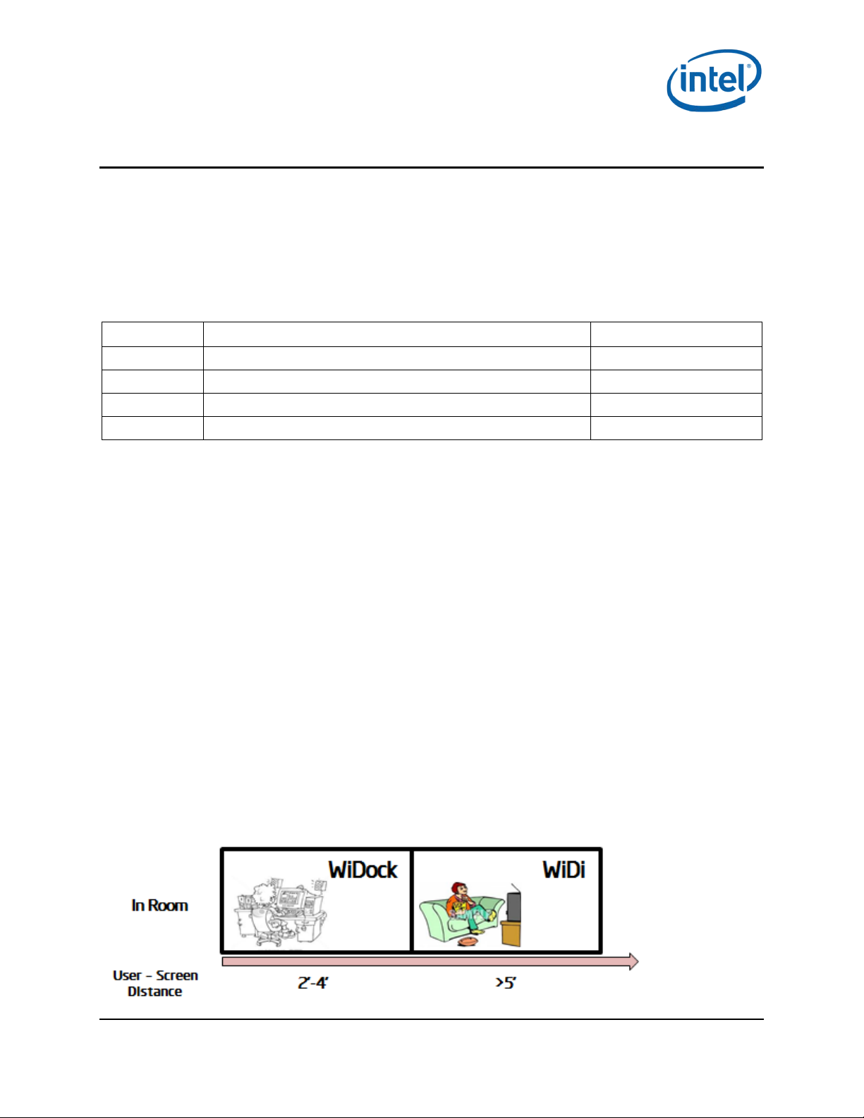
1.3.1 Wireless docking
Wireless Docking generally occ urs when the user is working 2-4 feet from the display(s). The user
experiences the same kind of responsiveness as operating a workstation/desktop.
“Place to Dock, Snap to Go” experience 1.3.1.1
Wireless dockin g is d esigned to minimize user actions. After the initial WPS based pairing, the typical
user is able to “au to-dock,” meaning the device automatically connects to the dock and periphe r al
when in range of the dock. I n oth er w or ds , by the time the device is on the desk, it is already docked.
Undocking is as simple, allowing the user to grab the device and walk away.
Wireless Docking (WiDock) and Wireless Display (WiDi) 1.3.1.2
WiDock differs from other models, such as Miracast* or Intel® Wireless Display, in which the user is
further from the screen (such as on the couch or in a conference room), and is focused on content
consumption (watching a video, sharing a screen with others, gaming) ra ther than produc tivity or
content creation.
Figure 1-1 Use models
Intel® Maple Peak July 2014
User Guide Document Number: 537178-2.1
6 Intel Confidenti a l
Page 7

Introduction
1.3.2 Wireless peripheral
The wireless peripheral feature allows a device to int eract with high-speed USB peripherals over
WiGig. For example, a directly atta c hed storage device equipped with Maple Peak SNK would allow a
high-speed USB 3.0 connection with a Maple Pea k equipped tablet or notebook.
When connecting, many of the wireless docking capabilities would be applicable ( excluding of course
the display capabilities), allow ing USB 3.0 like th r oughputs (>1 Gbps) for on-desk distances.
1.3.3 Multi Gbps Device-to-Device
The Device-to-Device feature allows two peer devices (two PCs, two tablets, a PC and a tablet, etc.) to
establish a fat IP pipe (> Gbps) to enable all other D2D capabilities.
1.4 Key features
See the Maple Peak Releas e N otes.
1.5 SW and HW deliverables
See the EPS document (Reference #3).
1.6 Notebook platform preparations for WiDock
• Operating system:
− Microsoft* Windows* 7 32/64, Microsoft Windows 8.1U 64
• SW Pre-requisites for OEM tools (unnecessary with an operational stack):
− VC++ 2010 Redistributable Package
1.7 Known limitations
See the Maple Peak Releas e N otes.
§
July 2014 Intel® Maple Peak
Document Number: 537178-2.1 User Guide
Intel Confidential 7
Page 8
Maple Peak Setup
2 Maple Peak Setup
The Maple Peak setup consists of the followin g components:
• One WiGig link that contains M a ple P ea k on the NB side and Maple Peak SNK on the dock s ide.
Note: Note that each MpL-M card (the baseband) is connected to MpL-R card (the 60 Ghz radio)
• A PC that serves as the NB host
WiGig connectivity can be performed in two modes:
• Test mode – setup can perform a pre-defined set of traffic a ccording to the accomp a nying OEM
Tool application.
• Operational mode – real WiGig pairing, with WDE and WSE P ALs.
2.1 Operational mode
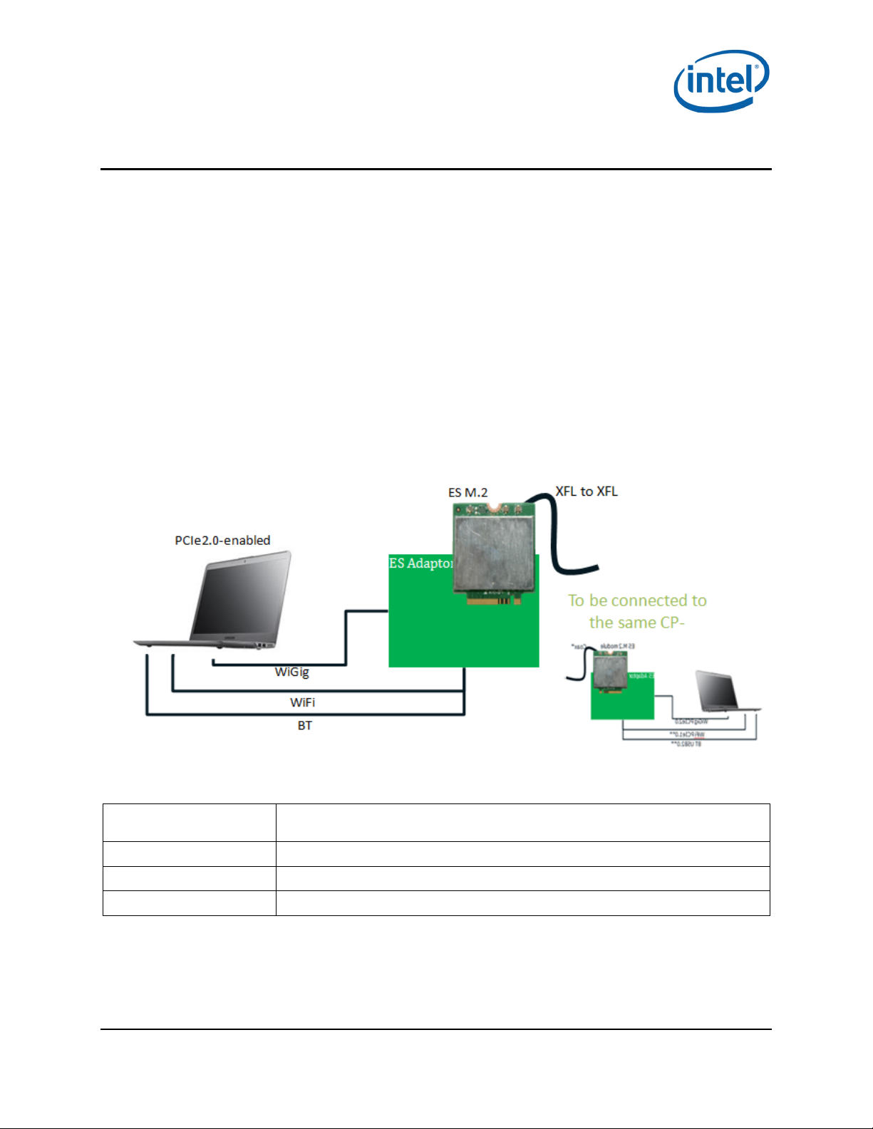
2.1.1 IF setup description (dock installer only)
Figure 2-1 IF setup
Table 2-1 IF setup description
Description
Maple Peak HW
Capabilities
Wired / OTA
Intel® Maple Peak July 2014
User Guide Document Number: 537178-2.1
8 Intel Confidenti a l
Table-top IF-to-IF (coaxial based) non-over-the-air reference-design setup for
client side
M.2 ES'; RFEM ES'
WSE; WDE
Wired (coaxial cable)*
Page 9
Fixed IPFixed IP
Ethernet switch
box
WTF
remote
agent
OEM Tool
Ethernet cable Ethernet cable
WiGig
Kit
(TX
)
Mini PCI Bus
WiGig
Kit
(RX)
Mini PCI Bus
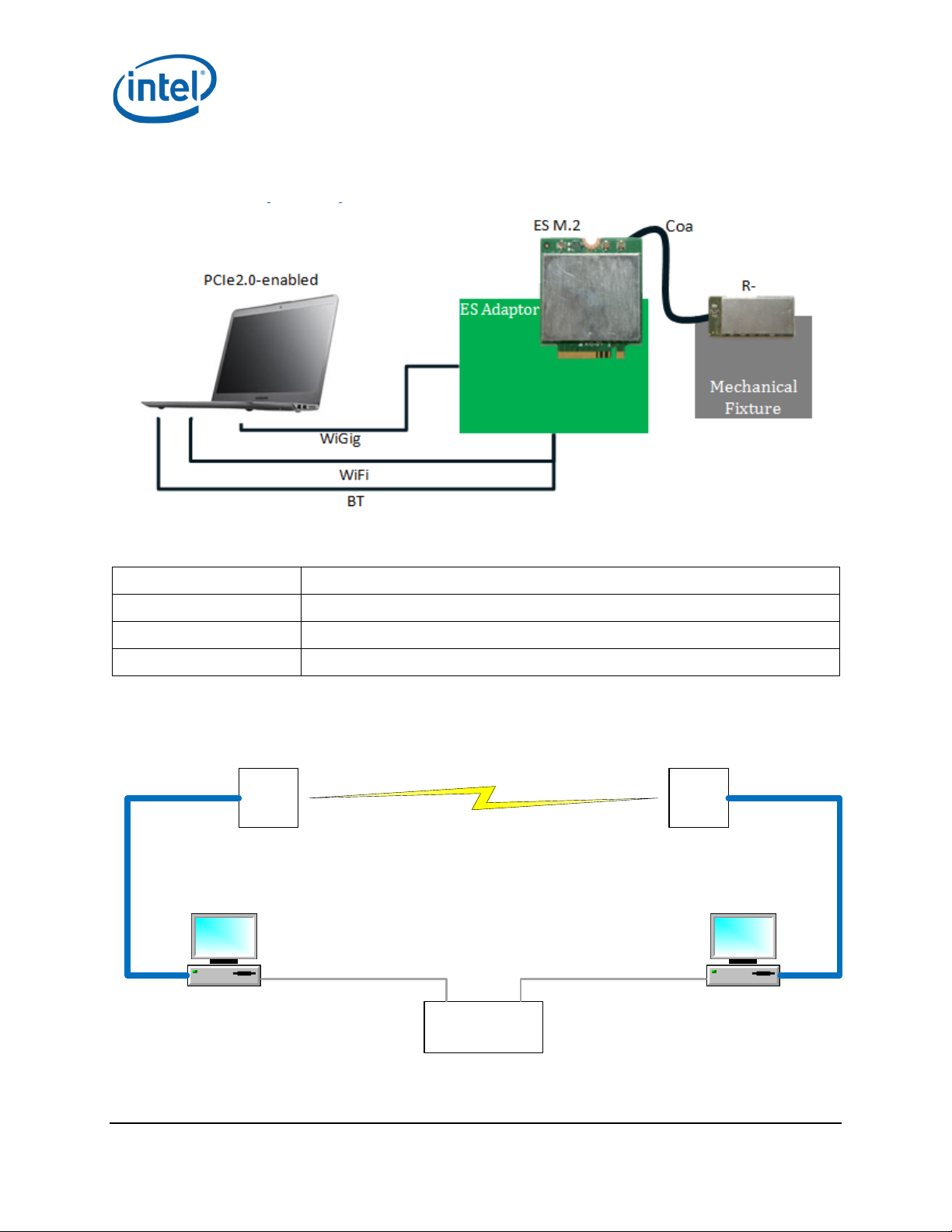
2.1.2 RF setup description
Figure 2-2 RF setup
Table 2-2 RF setup descript ion
Maple Peak Setup
Description
Maple Peak HW
Capabilities
Wired / OTA
Table-top over-the-air reference design setup for client side
WSE; WDE
M.2 ES'; RFEM ES'
OTA
2.2 Test mode (OEM tool setup environment)
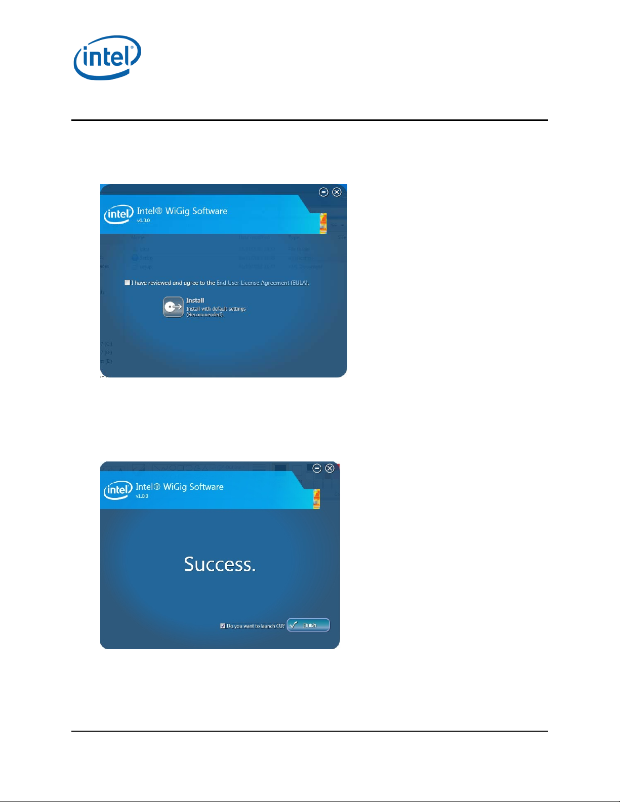
Figure 2-3 Maple Peak setup
July 2014 Intel® Maple Peak
Document Number: 537178-2.1 User Guide
Intel Confidential 9
Page 10

Maple Peak Setup
Figure 2 descriptions:
Two PCs (one per WiGig kit) are connected using a hub on the Ethernet NIC and can communicate
over a WiGig link.
The OEM tool application is installed on the left PC, and a small agent is in stalled the right P C (details
of how to install the s e c a n be found in the OEM Tool User Guide).
Note: A Test Mode setup should be insta ll ed to work in this configuration (see Section 3).
§
Intel® Maple Peak July 2014
User Guide Document Number: 537178-2.1
10 Intel Confidenti a l
Page 11
3 Software Install
3.1 NB side installation
1. Go to G Layout\Win7Plus\ and run Setup.exe.
Setup.exe installs th e r e levant insta lle r for either a 32-bit platfor m or a 64-bit platform.
Software Inst al l
2. Check I have rev iew ed a nd agr ee to th e EULA and click Install. This will install the opera tional
WiGig software for the NB.
3. When the application is s uccessfully installed check the Do you want to launch CU? option.
Select Finish.
You will be able to run the CU application from the desktop sh or tcut later if you do not check
this option.
July 2014 Intel® Maple Peak
Document Number: 537178-2.1 User Guide
Intel Confidential 11
Page 12

Software Inst al l
Note: During the firs t installation the device driver is installed and the follow ing “Windows
Security” pop-up may appear:
4. Choose Install this driver software anyway to contin ue the installation.
Note: To avoid this window, run the certifica te file (iCert.spc) from the Ce r tificates layout.
• Run setup.exe –q from a command line to run the ins taller in silent mode.
Note: The above installa tion is only f or RF setup. See the following section (Dock Side
Installation) and choose NoteBook to run an IF setup.
3.2 Dock side installation
3.2.1 Overview
The operational d oc k works without a host (hostless) and boots its F W from an inner flash memory.
When working with the OEM tool a host must be connec ted . The flash should be burned to the
updated version in one of two ways :
1. Over PCIe – A “loc a l” setup, in which the dock is not assem ble d and is attached to a PCIe cable.
The Dock Flash Burning (DFB) tool is used for flashing.
2. Over The Air (OTA) – A “remote” setup, in wh ic h the dock is connected to a c lient that can send
the dock FW upgr a de c ontent OTA using the CU application.
Note: Beta 1.0 did not support OTA FW upgrade. When upgrading f r om this version you m ust
first burn the flash using the DFB tool using the following steps:
1. Connect a host PC to the d oc k over PCIe and install the dock driver.
2. Use the DFB tool to burn the FW.
3. Disc onnect the PCI e from the dock; work hostless.
When the FW version is higher than Beta 1.0, it can be upgraded O T A (see Section
instructions) a nd no dock host insta llation is require d .
4.8 for
3.2.2 Dock host installation over PCIe
This installer sets up your Maple Peak in a few simple steps. N avigation between steps is possibl e
using the Back and Next buttons. Select Cancel to clos e the installer.
1. Uninstall previous dock drivers.
2. Go to OEM Layout\WiGigInstaller\ and run the WiGigInstaller.exe application.
Intel® Maple Peak July 2014
User Guide Document Number: 537178-2.1
12 Intel Confidenti a l
Page 13

Software Inst al l
3. Verify the following files are located in the insta ller folder:
a. WiGigInstaller_x**.msi
b. WiGigInstaller_DbgStack_x**.msi
The suffix x** means x86 for a 32-bit platform and x64 for a 64-bit platform.
Note: During the firs t installation the device driver is installed and the follow ing “Windows
Security” pop-up may appear:
4. Choose Install this driver software anyway and continu e the installer.
Select Operation Mode
There are two operation modes:
• Test mode: no broadcasting takes place. Primarily used for characterization by the OEM
Tool.
• Operational mode: the M aple Peak card is fully ac tive in either one of the ty p es in the next
step.
Note: A hostless dock is a lways in operation a l m od e, no matter what was selected in the
installation.
5. Choose Test Mode.
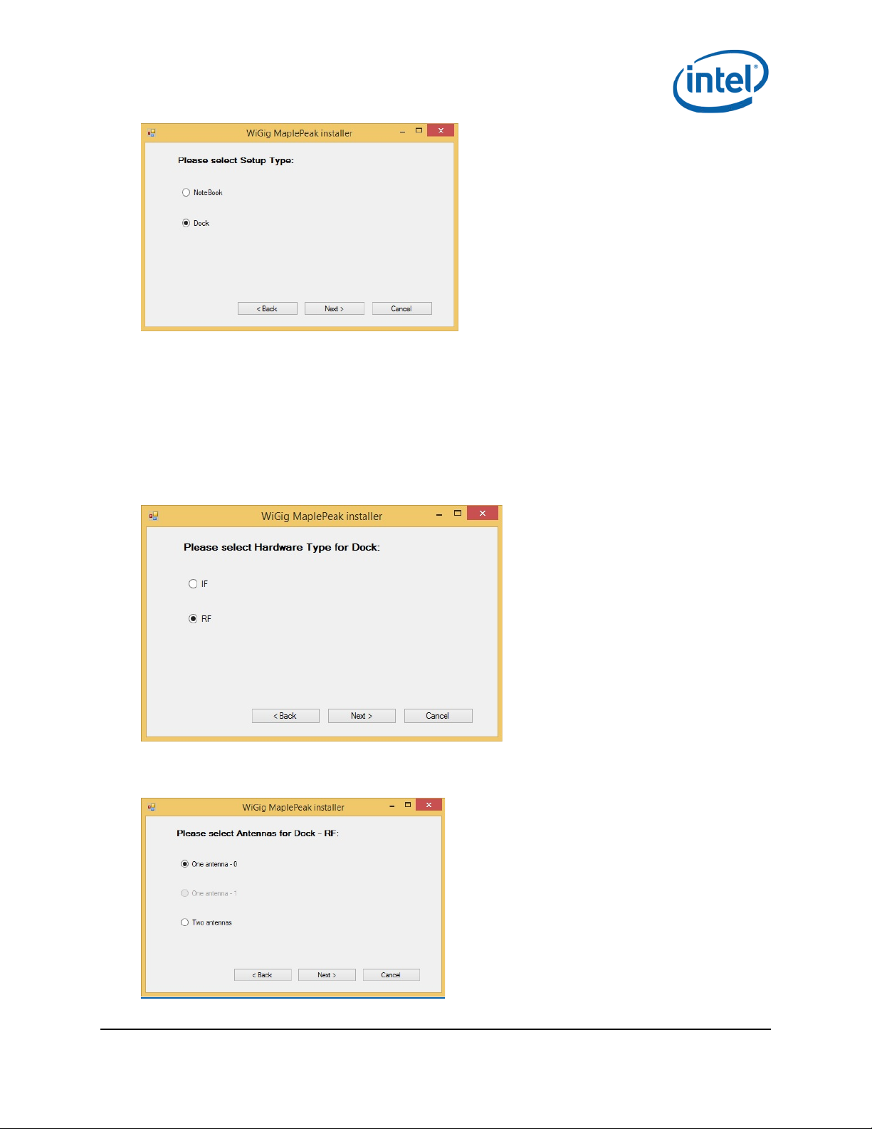
Select Setup Type
The Maple Peak card can be used for either notebook or doc k:
• Notebook: the notebook tran s m its data to the dock.
Dock: the dock receives and displays data from the notebook.
July 2014 Intel® Maple Peak
Document Number: 537178-2.1 User Guide
Intel Confidential 13
Page 14
Software Inst al l
Select Hardware Type
Maple Peak can communicate with another device via:
• IF (Intermediate Frequency ) : a cable is required between the ca r d ( XFL connector) and
another device.
• RF: the M.2 card is connected to the RFEM.
6. Select the relevant mode.
Choose IF mode if you ha ve no RFEM connected to the M.2. This has n o e ffect on the hostless
setup; it is in RF mode after disconnecting th e PCIe.
Select Number of Antennas
7. Select one antenna.
Intel® Maple Peak July 2014
User Guide Document Number: 537178-2.1
14 Intel Confidenti a l
Page 15

Select Stacks
8. Select stacks to install:
• Operational stack – Select
• Debug stack – Select
• NDIS driver – Don't Select
9. Click Install.
The installer ins talls and configures the card based on user specifications.
This process takes up to two minutes; a ver ification popup appea r s when successfully
completed.
Software Inst al l
Note: If you want to cha nge any selection in the installation, such as hardware type or setup
type, you will ne ed to uninstall the SW pa c kage (Windows->C ontrol Panel->Uninstall a
program) and install the a pp lic ation again.
3.2.3 Burning the flash using DFB tool
The DFB tool can b e found at C:/Program File s /Intel/WiGig/DFB/WiGigDockFlashBurner.exe.
Run the DFB applic a tion on the host to burn the dock Flash with the relevant FW version.
Run the application from the command line with the relevant parameters:
• For factory slot:
WiGigDockFlashBurner.exe --factory --package
"C:\Program Files\Intel\WiGig\Drivers\Dock_Image_Production.pack"
• For current slot:
WiGigDockFlashBurner.exe --package
"C:\Program Files\Intel\WiGig\Drivers\Dock_Image_Production.pack"
Note: Burn both the fac tory slot and the cu r r e nt slot.
• See DFB document (Reference #4) for detailed instructions on how to use the DFB tool.
§
July 2014 Intel® Maple Peak
Document Number: 537178-2.1 User Guide
Intel Confidential 15
Page 16

WiGig Applica tion User Ma nual
4 WiGig Application User Manual
The WiGig Connection Utility (CU) is a dedicated application that runs on the NB, lists available docks,
and creates a WiGig link with a selecte d d oc k.
The activity button and LEDs are used for connection/disconnection flows on the dock side.
Double click the W iG ig CU icon on the desktop to activate the CU application on the NB side unless you
checked the option to launch CU after ins ta lla tion (see Section 3.1 Step 3).
Note: The CU application keeps running f r om the system tray even if you click the X (close
window) icon on the application. Double-click the CU icon in the system tray to open the
CU again.
Note: The current WiGig CU is not the final ver sion and will be chan g ed in later releases.
4.1 Turn WiGig on
1. Click the grey OFF button to toggle the WiGig on once the CU application is running.
2. The CU scans for available docks and shows a list of docks with the following four statuses:
a. In range – paired: docks that are in range of the NB (f or example in the room o r cubicle)
and are already paired.
b. In range – not paired: docks that are in range of the NB but did not pair with it.
c. Incompatible: docks that are incompatible (incompatible FW version or non-interoperable
dock) and cannot be paired w ith this NB.
d. Out of range – paired: docks that were paired before but ar e c urrently not in range.
Intel® Maple Peak July 2014
User Guide Document Number: 537178-2.1
16 Intel Confidenti a l
Page 17

WiGig Applica tion User Ma nual
3. The dock name shown in the list (before pairing) is the ou t-of-box device name and is derived
from its MAC address.
4. A Connect button appears when a listed dock is selected.
4.2 Connect to a new dock
1. Select a non-paired dock and click Connect.
e. Connectin g to a dock for the firs t tim e (or to a dock that is set to Always P air) initiates
pairing with the dock.
2. The CU is now waiting for the us er to pres s th e function button on the device.
July 2014 Intel® Maple Peak
Document Number: 537178-2.1 User Guide
Intel Confidential 17
Page 18

WiGig Applica tion User Ma nual
3. The dock’s LED turns yellow.
4. Press the functional button on the d oc k to complete pairing. A connecting message shows on
the CU during the pairing process indicat ing that a connec tion is in progress.
5. When connected, the status in the CU changes to Connected and the dock’s LED turns green.
Intel® Maple Peak July 2014
User Guide Document Number: 537178-2.1
18 Intel Confidenti a l
Page 19

Note: The pairing process can take up to seven seconds. Future connections that don’t require
additional pairing take less time.
WiGig Applica tion User Ma nual
4.3 Manage the connections settings
Edit the connection s ettings by clicking the icon when the dock is c onnected. These are settings
for the specific Dock-N B connection.
The following can be set:
• Nickname: a personalized name that represents the specific NB-Dock connection.
The profile name can be modified by the user to a meaningfu l nam e s uch as “Joe office”, “Joe
home” etc. The profile name is shown in the docks list.
• Auto-connect: default; when checked the NB connects automa tic ally whenev e r it is in r ange of
the dock.
4.4 Change dock settings
The dock settings can be changed over-the-air after connecting a NB to the dock .
From the Connec tion Settings menu (see previous image) click Change Dock Settings (see following
image).
July 2014 Intel® Maple Peak
Document Number: 537178-2.1 User Guide
Intel Confidential 19
Page 20

WiGig Applica tion User Ma nual
1. General Info
a. Dock Name: the name that appears in the docks list i n the CU application .
b. Check for Firmware Update (Not supported in this r e lease): check if an updated FW
version is available for the dock.
2. Pairing
a. Always prompt devices to pair to th is dock: The dock will force pairing eac h time a device is
connecting
b. Manually connect: when checked the client has to manually connect (using the CU) with this
dock each time.
This setting is useful for public docks (for example in airports), to prevent a situation where
a NB that connecte d to the dock now automatically connects (unintentionally ) and prevents
other devices from connecting.
c. Preferred Channel: the preferred channel to work on (A utomatic, 1, 2, 3 or 4). The default is
Automatic, the device will choose the relev a nt channel based on the allow ed c hannels (under
regulation con s tr aints). This information is burnt in the OTP.
3. Password
Prevents non-authorized users from changing dock settings.
4.5 Disconnection
4.5.1 Managed undocking
The user can disconnect from the dock through the following s tep s :
1. Press the FUN_BUTTON on the dock for more than two seconds (long press).
Intel® Maple Peak July 2014
User Guide Document Number: 537178-2.1
20 Intel Confidenti a l
Page 21

2. Click Disconnect in the CU.
The dock’s LED turns off and the dock’s monitor and devices disconnect.
In auto-connect profiles undesired auto-connection will be blocked after a managed undocking until
one of the following conditions apply :
• User exits the dock’s range
• Client resumes f r om a low-power mode (S3/S4/S5 S0) (not currently supported).
WiGig Applica tion User Ma nual
4.5.2 Spontaneous undocking
When the user exits the range of the dock without making a manage d d is c onnection, the lin k drops
after attempts to recover. The dock’s LED powers off after the link drops.
4.6 Forget this dock
Choose the dock and click Forget this d oc k to delete a dock profile. This deletes the profile of the dock
and requires a manual connection and pairing for the next connection. (This option is only available
when the relevant dock is not connected).
4.7 Docking
4.7.1 Automatic docking
A connection to th e d oc k begins automatically when the dock is configured to a uto-connect and the
user enters the dock’s range. The NB’s lid can be open or closed.
July 2014 Intel® Maple Peak
Document Number: 537178-2.1 User Guide
Intel Confidential 21
Page 22

WiGig Application User Manual
• The dock LED turns green, docking is completed within a few seconds, and the dock monitor
shows the display.
4.7.2 Manual docking
No connection is initiated when the dock is configur ed to m a nually connect and the user enter s the
dock’s range. The dock’s LED stays off.
Clicking Connect in the CU next to the dock’s name begins the docking process. Once docking is
complete the dock’s LED turns green and the docking monitor shows the display .
4.8 Dock FW upgrade
The dock FW can be upgraded using the CU application. The dock’s FW upgrade does not occur
automatically; it requires the user’s initiation to allow f or user control of the process.
Upgrade the FW from the CU Dock Settings screen.
Click the Upgrade button and choose the Dock Image.
To choose the same version installed on the NB s ide go to C:/ProgramFiles/Intel/WiGig/Drivers and
choose Dock_Image.pack.
A progress indication for the proces s displays in the C U . If the upgrade fails , the previous version
remains and th e user is notified.
When completed, a reset is performed and the device is up with the new version. Close th e window.
Intel® Maple Peak July 2014
User Guide Document Number: 537178-2.1
22 Intel Confidenti a l
Page 23
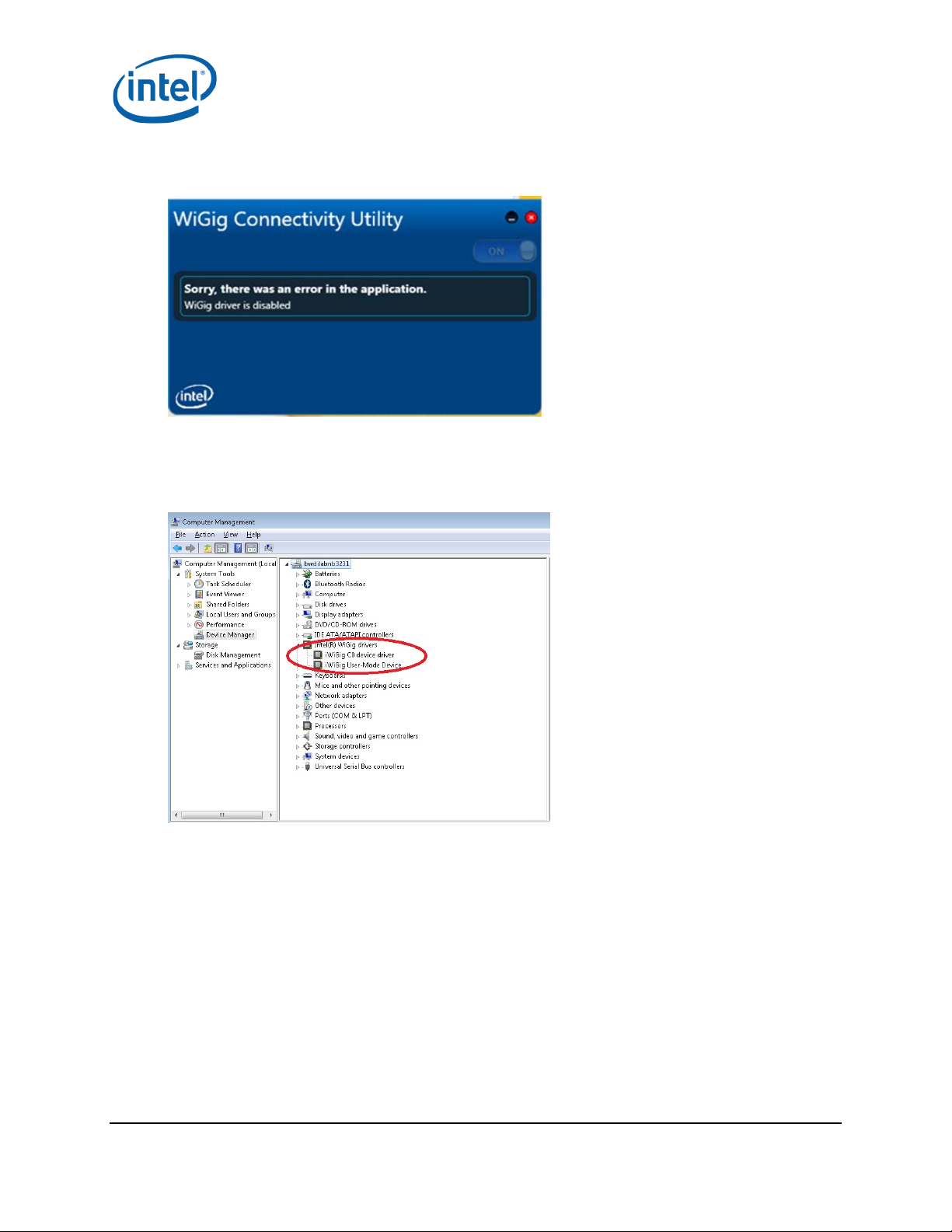
4.9 Troubleshooting
Follow these steps for a “WiGig driver is disabled” error:
• Exit the CU applica tion (right-click in the tray icon)
• Disable the WiGig device driver in the Device Manager
• Enable the device driver again
• Run the CU applica tion
WiGig Applica tion User Ma nual
§
July 2014 Intel® Maple Peak
Document Number: 537178-2.1 User Guide
Intel Confidential 23
Page 24

WiGig Recording Tool (WiGRT)
5 WiGig Recording Tool (WiGRT)
The WiGRT is a tool that ena b les fast and easy debugging of the WiGig pr od uct by continuously
capturing information from th e WiGig device and driver.
The WiGRT tool captures information continuously, allowing debug of an issue without (necessarily)
the need to reprodu ce it. The information is collected in a cyclic manner , saving sufficient data and
consuming a limited amount of memory. The user can “Generate a report” at any time and send the
zip file to Intel engineers f or debug.
5.1 WiGRT installation
The WiGRT tool installer is not part of the ope r a tional installer . It should be ins ta lle d and run after
installation of the WiGig operational installer, to s tart capturing information imm ediately.
1. From the diagnostics layout, run the Diagnostics.exe self-extracted file. Then run WiGRT.bat
from the root path. It will run the relevant installer f or your OS, either for 32-bit or 64-bit.
2. Click Next.
3. Check “I accept the terms in the License Agreement.”
Intel® Maple Peak July 2014
User Guide Document Number: 537178-2.1
24 Intel Confidenti a l
Page 25

4. Choose Complete.
WiGig Recording Tool (WiGRT)
5. Click Finish.
July 2014 Intel® Maple Peak
Document Number: 537178-2.1 User Guide
Intel Confidential 25
Page 26
WiGig Recording Tool (WiGRT)
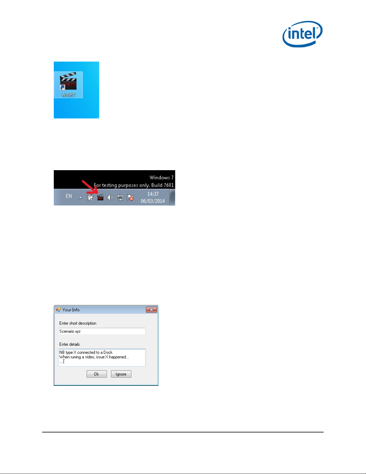
See the following icon on your desktop:
Note: The application starts running automatically. The icon is in the s ystem tray.
5.2 How to use WiGRT
The WiGRT tool runs in the back ground from the system tray and requires minimum intervention of
the user.
It starts captur ing information imm ediately.
Right-click the WiGRT icon to show a m enu with three options :
• Generate Report
• Settings
• Exit (to close the application and stop capturing data)
5.2.1 Generate Report menu
Click Generate Report from the WiGRT menu to document an issue to report to Intel’s engineer s.
Enter details about the specific issue in the popup window (exa m ple ima ge follows).
Note: Adding your information is highly recommended but is not mandatory.
Selecting Ok (or Ignore if you didn’t enter deta ils) saves a zip file under
%ProgramData%\Intel\WiGig\WiGRT\logs.
The name of the zip file includes the computer n a me, the date and the time to easily identify the
relevant report (zip format example: COMPUTERNAME323-060314-144436).
This zip file should be sent to Intel’s engineers for f urther investigat ion.
Intel® Maple Peak July 2014
User Guide Document Number: 537178-2.1
26 Intel Confidenti a l
Page 27

WiGig Recording Tool (WiGRT)
5.2.2 Settings menu
The Settings menu is available to provide additional debugging capabilities a nd should only be used
when instructed by Intel’s engine ers.
XML settings 5.2.2.1
When additional or different information is required for a specific scenario, you might have to choos e
settings from the list and click Set. This will send the device th e info in the XML file with the relevant
settings.
The WiGRT tool ins ta ller provides a few XML files for pre-defined scenarios. If you are working with an
Intel engineer on a specific iss ue, you might receive a proprietary XML file; place the XM L file under:
%ProgramData%\Intel\WiGig\WiGRT\Settings.
Figure 5-1 XML settings
§
July 2014 Intel® Maple Peak
Document Number: 537178-2.1 User Guide
Intel Confidential 27
Page 28

Regulatory Information
This section provides regulatory information for the following wireless adapters:
Intel® Wireless Gigabit Sink W13100
NOTE: Due to the evolving state of regulations and standards in the wireless LAN field
(IEEE 802.11 and similar standards), the information provided herein is subject to change.
Intel Corporation assumes no responsibility for errors or omissions in this document.
INFORMATION FOR THE USER
Safety Notices
USA FCC Radio Frequency Exposure
The FCC with its action in ET Docket 96-8 has adopted a safety standard for human
exposure to radio frequency (RF) electromagnetic energy emitted by FCC certified
equipment. The wireless adapter meets the Human Exposure limits found in OET Bulletin
65, supplement C, 2001, and ANSI/IEEE C95.1, 1992. Proper operation of this radio
according to the instructions found in this manual will result in exposure substantially below
the FCC’s recommended limits.
The following safety precautions should be observed:
Do not touch or move antenna while the unit is transmitting or receiving.
Do not hold any component containing the radio such that the antenna is very close
or touching any exposed parts of the body, especially the face or eyes, while
transmitting.
Do not operate the radio or attempt to transmit data unless the antenna is
connected; this behavior may cause damage to the radio.
Use in specific environments:
The use of wireless adapters in hazardous locations is limited by the
constraints posed by the safety directors of such environments.
The use of electronic devices equipped with wireless adapters on airplanes is
governed by rules for each commercial airline operator.
The use of wireless adapters in hospitals is restricted to the limits set forth by
each hospital.
Explosive Device Proximity Warning
The linked image cannot be displayed . The file may have been
moved, renamed, or deleted. Ver ify that the link points to the
correct file and location.
Warning: Do not operate a portable transmitter (including this wireless adapter) near
unshielded blasting caps or in an explosive environment unless the transmitter has been
modified to be qualified for such use.
Use On Aircraft Caution
Page 29

The linked image cannot be displayed. The
file may have been moved, renamed, or
deleted. Verify that the link poin ts to the
correct file and location.
Caution: Regulations of commercial airline operators may prohibit airborne operation of
certain electronic devices equipped with radio-frequency wireless devices (wireless
adapters) because their signals could interfere with critical aircraft instruments.
Other Wireless Devices
Safety Notices for Other Devices in the Wireless Network: See the documentation
supplied with wireless adapters or other devices in the wireless network.
Local Restrictions on 802.11a, 802.11b, 802.11g, 802.11n, and 802.16e Radio
Usage
The linked image cannot be displayed. The
file may have been moved, renamed, or
deleted. Verify that the link poin ts to the
correct file and location.
Caution: Due to the fact that the frequencies used by 802.11ad wireless devices may
not yet be harmonized in all countries, 802.11ad products are designed for use only in
specific countries, and are not allowed to be operated in countries other than those of
designated use. As a user of these products, you are responsible for ensuring that the
products are used only in the countries for which they were intended and for verifying that
they are configured with the correct selection of frequency and channel for the country of
use. Any deviation from the permissible power and frequency settings for the country of use
is an infringement of national law and may be punished as such.
The Wireless Adapter and Your Health
The wireless adapter, like other radio devices, emits radio frequency electromagnetic
energy. The level of energy emitted by the wireless adapter, however, is less than the
electromagnetic energy emitted by other wireless devices such as mobile phones. The
wireless adapter operates within the guidelines found in radio frequency safety standards
and recommendations. These standards and recommendations reflect the consensus of the
scientific community and result from deliberations of panels and committees of scientists
who continually review and interpret the extensive research literature. In some situations or
environments, the use of the wireless adapter may be restricted by the proprietor of the
building or responsible representatives of the applicable organization. Examples of such
situations may include:
Using the wireless adapter on board airplanes, or
Using the wireless adapter in any other environment where the risk of interference
with other devices or services is perceived or identified as being harmful.
If you are uncertain of the policy that applies to the use of wireless adapters in a specific
organization or environment (an airport, for example), you are encouraged to ask for
authorization to use the adapter before you turn it on.
REGULATORY INFORMATION
USA - Federal Communications Commission (FCC)
Page 30

No configuration controls are provided for Intel® wireless adapters allowing any change in
the frequency of operations outside the FCC grant of authorization for U.S. operation
according to Part 15 of the FCC rules.
Intel® wireless adapters are intended for OEM integrators only.
Intel® wireless adapters cannot be co-located with any other transmitter unless
approved by the FCC.
This wireless adapter complies with Part 15 of the FCC Rules. Operation of the device is
subject to the following two conditions:
This device may not cause harmful interference.
This device must accept any interference that may cause undesired operation.
Class B Device Interference Statement
This wireless adapter has been tested and found to comply with the limits for a Class B
digital device, pursuant to Part 15 of the FCC Rules. These limits are designed to provide
reasonable protection against harmful interference in a resident ial installation. This wireless
adapter generates, uses, and can radiate radio frequency energy. If the wireless adapter is
not installed and used in accordance with the instructions, the wireless adapter may cause
harmful interference to radio communications. There is no guarantee, however, that such
interference will not occur in a particular installation. If this w ireless adapt er does cause
harmful interference to radio or television reception (which can be determined by turning
the equipment off and on), the user is encouraged to try to correct the interference by
taking one or more of the following measures:
Reorient or relocate the receiving antenna of the equipment experiencing the
interference.
Increase the distance between the wireless adapter and the equipment experiencing
the interference.
Connect the computer with the wireless adapter to an outlet on a circuit different
from that to which the equipment experiencing the interference is connected.
Consult the dealer or an experienced radio/TV technician for help.
NOTE: The adapter must be installed and used in strict accordance with the manufacturer's
instructions as described in the user documentation that comes with the product. Any other
installation or use will violate FCC Part 15 regulations.
Canada – Industry Canada (IC)
This device complies with Industry Canada licence-exempt RSS standard(s). Operation is
subject to the following two conditions: (1) this device may not cause interference, and (2)
this device must accept any interference, including interference that may cause undesired
operation of the device.
Cet appareil se conforme aux normes Canada d'Industrie de RSS permis-exempt.
L'utilisation est assujetti aux deux conditions suivant es: (1) cet appareil ne peut pas causer
Page 31

d'interférences, et (2) cet appareil doit accepter des interférences , y compris des
interférences qui peuvent causer desopérations non désirées de l'appareil.
Caution: When using IEEE 802.11a wireless LAN, this product is restricted to indoor use
due to its operation in the 5.15- to 5.25-GHz frequency range. Industry Canada requires
this product to be used indoors for the frequency range of 5.15GHz to 5.25GHz to reduce
the potential for harmful interference to co-channel mobile satellite systems. High power
radar is allocated as the primary user of the 5.25- to 5.35-GHz and 5.65 to 5.85-GHz bands.
These radar stations can cause interference with and/or damage to this device. The
maximum allowed antenna gain for use with this device is 6dBi in order to comply with the
E.I.R.P limit for the 5.25- to 5.35 and 5.725 to 5.85GHz frequency range in point-to-point
operation. To comply with RF exposure requirements all antennas should be located at a
minimum distance of 20cm, or the minimum separation distance allowed by the module
approval, from the body of all persons.
Attention: l'utilisation d'un réseau sans fil IEEE802.11a est restreinte à une utilisation en
intérieur à cause du fonctionnement dans la bande de fréquence 5.15-5.25 GHz. Industry
Canada requiert que ce produit soit utilisé à l'intérieur des bâtiments pour la bande de
fréquence 5.15-5.25 GHz afin de réduire les possibilités d'interférences nuisibles aux canaux
co-existants des systèmes de transmission satellites. Les radars de puissances ont fait
l'objet d'une allocation primaire de fréquences dans les bandes 5.25-5.35 GHz et 5.65-5.85
GHz. Ces stations radar peuvent créer des interférences avec ce produit et/ou lui être
nuisible. Le gain d'antenne maximum permissible pour une utilisation avec ce produit est de
6 dBi afin d'être conforme aux limites de puissance isotropique rayonnée équivalente
(P.I.R.E.) applicable dans les bandes 5.25-5.35 GHz et 5.725-5.85 GHz en fonctionnement
point-à-point. Pour se conformer aux conditions d'exposition de RF toutes les antennes
devraient être localisées à une distance minimum de 20 cm, ou la distance de séparation
minimum permise par l'approbation du module, du corps de toutes les personnes.
Under Industry Canada regulations, this radio transmitter may only operate using an
antenna of a type and maximum (or lesser) gain approved for the transmitter by Industry
Canada. To reduce potential radio interference to other users, the antenna type and its gain
should be so chosen that the equivalent isotropically radiated power (e.i.r.p.) is not more
than that necessary for successful communication.
Selon les règlements de Canada d'Industrie, cet émetteur de radio peut seulement
fonctionner en utilisant une antenne du type et de gain maximum (ou moindre) que le gain
approuvé pour l'émetteur par Canada d'Industrie. Pour réduire lesinterférences radio
potentielles avec les autres utilisateurs, le type d'antenne et son gain devraient être choisis
de façon à ce que la puissance isotrope rayonnée équivalente(P.I.R.E.) ne soit pas
supérieure à celle qui est nécessaire pour une communication réussie.
European Union
This equipment complies with the essential requirements of th e European Union directive
1999/5/EC. See Statements of European Union Compliance
European Union Declarations of Conformity
.
Page 32

To view the European Union Declaration of Conformity for your adapter, perform these
steps.
1. Open this web site: http://developer.intel.com/design/litcentr/ce_docs/index.htm.
2. Under the Wireless Products menu select your adapter.
3. Click Go.
To view additional regulatory information for your adapter, perform these steps:
1. Open this web site: http://www.intel.com/support/wireless/wlan/
2. Click on the link for your adapter.
3. Click Document and Guides.
4. Under Regulatory Information, click Regulatory documents for your adapter.
Waste Electrical and Electronic Equipment Directive (WEEE)
The linked image cannot be displayed. The file may have been moved, renamed, or deleted. Verify that the link points to the correct file and location.
Restriction of Hazardous Substances Directive (RoHS) Compliant
All products described herein are compliant with the European Union' s RoHS Directive.
For CE Mark-Related Questions related to the wireless adapter, contact:
Intel Corporation Attn: Corporate Quality 2200 Mission College Blvd. Santa Clara, CA
95054-1549 USA
Safety Approval Considerations
This device has been safety approved as a component and is for use only in complete
equipment where the acceptability of the combination is determined by the appropriate
safety agencies. When installed, consideration must be given to the followin g :
It must be installed into a compliant host device meeting the requ irement of
UL/EN/IEC 60950-1 2nd edition including the general provisions of enclosure design
1.6.2 and specifically paragraph 1.2.6.2 (Fire Enclosure).
The device shall be supplied by a SELV source when installed in the end-use
equipment.
A heating test shall be considered in the end-use product for meeting the
requirement of UL/EN/IEC 60950-1 2nd edition.
Page 33

Low Halogen
Applies only to brominated and chlorinated flame retardants (BFRs/CFRs) and PVC in the
final product. Intel components as well as purchased components on the finished assembly
meet JS-709 requirements, and the PCB / substrate meet IEC 61249-2-21 requirements.
The replacement of halogenated flame retardants and/or PVC may not be better for the
environment.
Mexico
La operación de este equipo está sujeta a las siguientes dos condiciones: (1) es posible que
este equipo o dispositivo no cause interferencia perjudicial y (2) este equipo o dispositivo
debe aceptar cualquier interferencia, incluyendo la que pueda causar su operación no
deseada.
Modular Regulatory Certification Country Markings
A list of countries requiring regulatory markings is available. Note that the lists include only
countries requiring marking but not all certified countries. To f in d th e regulatory country
marking information for your adapter, perform these steps:
1. Open this web site: http://www.intel.com/support/wireless/wlan/
2. Click on the link for your adapter.
3. Click Document and Guides.
4. Under Regulatory Information, click Regulatory documents for your adapter.
INFORMATION FOR OEMs and HOST INTEGRATORS
The guidelines described within this document are provided to OEM integrators installing
Intel® wireless adapters in notebook and tablet PC host platforms. Adherence to these
requirements is necessary to meet the conditions of complianc e with FCC rules, including RF
exposure. When all antenna type and placement guidelines described herein are fu lfilled the
Intel® wireless adapters may be incorporated into notebook and tablet PC host platforms
with no further restrictions. If any of the guidelines described herein are not satisfied it may
be necessary for the OEM or integrator to perform additional testing and/or obtain additional
approval. The OEM or integrator is responsible to determine the required host regulatory
testing and/or obtaining the required host approvals for compliance.
Intel® wireless adapters are intended for OEMs and host integrators only.
The Intel® wireless adapter FCC Grant of Authorization describes any limited
conditions of modular approval.
The Intel® wireless adapters must be operated with an access point that has been
approved for the country of operation.
Page 34

Changes or modification to Intel® wireless adapters by OEMs, integrators or other
third parties is not permitted. Any changes or modification to Intel® wireless
adapters by OEMs, integrators or other third parties will void authorization to operate
the adapter.
Simultaneous Transmission of Intel® Wireless Adapters with Other
Integrated or Plug-In Transmitters
Based upon FCC Knowledge Database publication number 616217
https://apps.fcc.gov/oetcf/kdb/forms/FTSSearchResultPage.cfm?id=33240&switch=P
there are multiple transmitting devices installed in a host device, an RF exposure
transmitting assessment shall be performed to determine the necessary application and test
requirements. OEM integrators must identify all possible combinations of simultaneous
transmission configurations for all transmitters and antennas installed in the host system.
This includes transmitters installed in the host as mobile devices (>20 cm separation from
user) and portable devices (<20 cm separation from user). OEM integrators should consult
the actual FCC KDB 616217 document for all details in making this assessment to determine
if any additional requirements for testing or FCC approval is necessary.
, when
Information To Be Supplied to the End User by the OEM or Integrator
The following regulatory and safety notices must be published in documentation supplied to
the end user of the product or system incorporating the Intel® wireless adapter, in
compliance with local regulations. Host system must be labeled with "Contains FCC ID:
XXXXXXXX", FCC ID displayed on label.
The Intel® wireless adapter must be installed and used in strict accordance with the
manufacturer's instructions as described in the user documentation that comes with the
product. Intel Corporation is not responsible for any radio or television interference caused
by unauthorized modification of the devices included with the wireless adapter kit or the
substitution or attachment of connecting cables and equipment other than that specified by
Intel Corporation. The correction of interference caused by such unauthorized modification,
substitution or attachment is the responsibility of the user. Intel Corporation and authorized
resellers or distributors are not liable for any damage or violation of government regulations
that may arise from the user failing to comply with these guidelines.
 Loading...