

Page 1
OPEN (660) 120/140/150 II
12.1" /14.1" /15.1" TFT
Intel® Celeron/Pentium® III
Multimedia Open-frame Panel PC
User’s Manual (version 2.1)
Page 2

Copyright Notice
This document is copyrighted, 2001 by the Manufacturer.
The information provided in this document has been
carefully checked and is accurate at the time of publication.
However, the Manufacturer assumes no responsibility for
any infringements of patents or other rights of third parties
that may result from its use.
No part of this publication may be reproduced, stored in a
retrieval system, or transmitted in any form of or via any
means without the prior written permission of the
Manufacturer. Further, this publication and features
described herein are subject to change without notice.
Trademarks
All brand and product names used for identification in this
document are trademarks or registered trademarks of their
respective companies.
© Copyright 2001, Feb. Version 2.1
All rights reserved.
Printed in Taiwan
Page 3

Unpacking
After unpacking the OPEN (660) system carton, check
and see if the following items are included and in good
condition.
l OPEN (660) 120/140/150 II main system x 1
l Accessories
- Power cord x 1
- External FDD cable x 1
- External IDE cable x 1
- External FDD & HDD power cable x 1
- User manual diskette in .pdf format x 1
- Utilities & drivers diskettes x 6
- Touchscreen drivers x 1 set
or utilities and drivers CD diskette x 1
(for touchscreen drivers, please download the
updated drivers from the following website
http://www.microtouch.com or
http://www.elotouch.com
- Mounting kit for system mounting x 2 sets
- Screw packet
l Warranty card
Make sure that all of the items listed above are present. If
any of the above items is missing, contact your dealer
immediately.
Warranty
All products manufactured by the manufacturer are
warranted against defective materials for one year starting
from the date of delivery to the original purchaser.
Page 4

Important Safety Precautions
Before getting started, read these instructions and save
them for later reference.
1. Turn off the computer before cleaning. Clean with a
damp or dry cloth only. Do not spray any liquid cleaner
on screen directly.
2. The power outlet socket used to plug in the computer
power cord must be located near the system and easily
accessible. Do not use outlets on the same circuit of
the systems that regularly switched on and off.
3. Make sure the voltage of the power source is correct
before connecting the computer to the power outlet.
4. If the computer is sharing an extension cord with other
devices, make sure the total ampere rating of the
devices plugged into the extension cord does not
exceed the cord’ s ampere rating.
5. Do not expose the power cord, extension cord and
power outlet to moisture.
6. Install the computer on a reliable surface to prevent
damage caused by dropping.
7. This computer is not equipped with an operating
system. An operating system must be loaded first
before installing any software into the computer.
8. Disconnect the power cord from the computer before
any installation. Make sure both the computer and the
external devices are turned off. The sudden surge of
power may ruin any sensitive components. Also make
sure the computer is properly grounded.
9. During installation of any internal components, be sure
to ground yourself to keep from any static charge.
Most electronic components are sensitive to the static
electric charge. Use a grounding wrist strap and place
all electronic components in any static-shielded
devices.
Page 5

10. The openings on the computer enclosure are for the
cabin ventilation to prevent the computer from
overheating. DO NOT COVER THE OPENINGS.
11. The brightness of the flat panel display will decrease
with use. However, hours of use will vary depending on
the application environment.
12. If the computer is equipped with a touch panel, avoid
using sharp objects to operate the touch panel.
Scratches on the touch panel may cause malcalibration or non-function to the panel.
13. The LCD panel display is not subject to shock or
vibration. When assembling the computer, make sure
it is securely installed.
Page 6

Table of Contents
1. INTRODUCTION............................................. 1-1
1.1. GENERAL INFORMATION ..................................1-2
1.2. WHAT COVERS IN THIS MANUAL.........................1-3
1.3. SPECIFICATIONS ...........................................1-5
1.4. DIMENSIONS ...............................................1-9
1.5. OPTIONAL MODULES & ACCESSORIES................1-11
1.5.1. Touchscreen Module .............................1-11
2. IDENTIFYING THE SYSTEM COMPONENTS... 2-13
2.1. FRONT VIEW .............................................2-14
2.2. SIDE VIEWS..............................................2-15
2.3. I/O OUTLETS ............................................2-16
2.4. SYSTEM MAJOR PARTS..................................2-18
2.5. SYSTEM SETUP FOR THE FIRST-TIME USE ............2-19
2.5.1. Installation Procedures..........................2-19
2.5.2. Running the BIOS Setup .......................2-20
2.5.3. Operating System and Driver Installation 2-21
3. MOUNTING OPTIONS................................... 3-23
3.1. DIFFERENT FRONT BEZELS .............................3-24
3.1.1. OPEN (660) system with Small Bezel......3-24
3.1.2. OPEN (660) system with Big Bezel .........3-25
3.1.3. Aluminum Alloy Frame..........................3-26
3.2. METAL FIXTURES ........................................3-27
3.2.1. Metal Fixture A....................................3-27
3.2.2. Metal Fixture B.....................................3-28
3.3. FRONT MOUNTING .......................................3-29
3.3.1. Front Mounting with Touchscreen Module 3-29
3.3.2. Front Mounting w/o Touchscreen Module.3-30
3.4. REAR MOUNTING ........................................3-32
3.4.1. Fixing on the Enclosure’s front panel.......3-33
3.4.2. Fixing on the Enclosure’s back panel.......3-34
3.5. PANEL MOUNTING .......................................3-36
Page 7

4. SYSTEM HARDWARE INSTALLATION ........... 4-37
4.1. INSTALLING THE CPU...................................4-39
4.2. INSTALLING THE SDRAM MEMORY MODULE ........4-40
4.3. INSTALLING THE HDD ..................................4-41
4.3.1. OPEN 120/140 2.5" HDD Installation ......4-41
4.3.2. OPEN 150 3.5" HDD Installation............4-42
4.4. INSTALLING THE FDD...................................4-43
4.4.1. External FDD connection .......................4-43
4.4.2. Internal FDD installation for OPEN 150....4-44
4.5. INSTALLING THE CD-ROM DRIVE.....................4-45
4.5.1. External CD-ROM connection .................4-45
4.5.2. Installing Internal CD-ROM for OPEN 150 4-46
4.6. EXPANSION SLOT........................................4-47
5. I/O CONNECTION........................................ 5-49
5.1. VGA INTERFACE.........................................5-50
5.2. COM PORTS X 4 ........................................5-51
5.3. PARALLEL PORT ..........................................5-53
5.4. 100/10 BASE-T ETHERNET (RJ-45)................5-53
5.5. USB PORTS..............................................5-54
5.6. AUDIO INTERFACE .......................................5-54
5.7. EXTERNAL FDD (DB-15) .............................5-55
5.8. +5V/12V DC-OUT ....................................5-56
5.9. PS/2 KEYBOARD INTERFACE...........................5-56
5.10. PS/2 MOUSE ............................................5-56
5.11. AC/DC INLET/POWER SWITCH .......................5-56
6. SYSTEM CONTROL BOARD ........................... 6-57
6.1. INTRODUCTION ..........................................6-58
6.1.1. General Information .............................6-58
6.1.2. Features..............................................6-59
6.1.3. Specifications.......................................6-60
6.1.4. Board Placement & Dimension ...............6-62
Page 8

6.2. LOCATING JUMPERS & CONNECTORS .................6-63
6.2.1. Jumpers & Jumper Setting.....................6-64
6.2.1.1. DOC 2000 Address Setting (JP9).......6-65
6.2.1.2. COM 2 RS-232/485 Setting (JP3,5,6) 6-65
6.2.1.3. CMOS Clear Setting (JP4) ................6-66
6.2.1.4. LCD Power Setting (JP1)..................6-66
6.2.2. Connectors & Pin Assignment.................6-67
6.2.2.1. CN12: Main Power Connector ...........6-68
6.2.2.2. CN2/IDE1: IDE Connector................6-69
6.2.2.3. CN3/CN1: Flat Panel Connector ........6-71
6.2.2.4. CN5: IR and Serial Ports Connector...6-73
6.2.2.5. CN7: Digital I/O Connector ..............6-74
6.2.2.6. CN8: KB, MS, USB & PRT Connector..6-75
6.2.2.7. CN10: CD Audio Input Connector......6-76
6.2.2.8. CN9: Audio, LAN, VGA CRT & LED ....6-76
6.2.2.9. CN6: Video Interface Connector........6-77
6.2.2.10. FDC1: FDD Connector .....................6-78
6.2.2.11. FAN1: FAN Connector ......................6-78
6.2.2.12. CN4: PCI/ISA Expansion Slot ...........6-79
7. AWARD BIOS SETUP.................................... 7-83
7.1. AWARD BIOS............................................7-84
7.2. CONTROL KEY DEFINITION.............................7-85
7.3. GETTING HELP ...........................................7-86
7.3.1. Main Menu...........................................7-86
7.4. AWARD BIOS SETUP .................................7-87
7.4.1. AWARD BIOS Setup Main Menu..............7-87
7.4.2. Standard CMOS Setup ..........................7-89
7.4.3. BIOS Features Setup ............................7-92
7.4.4. Chipset Features Setup.........................7-93
7.4.5. Power Management Setup.....................7-94
7.4.6. PnP/PCI Configuration...........................7-95
7.4.7. Load BIOS Defaults ..............................7-96
7.4.8. Load Setup Defaults .............................7-97
7.4.9. Integrated Peripherals Setup .................7-98
7.4.10. User Password .....................................7-99
7.4.11. IDE HDD Auto Detection......................7-100
7.4.12. Save and Exit Setup ...........................7-101
7.4.13. Exit Without Saving............................7-101
Page 9

8. SOFTWARE DRIVERS INTRODUCTIONS ..... 8-103
8.1. ETHERNET DRIVERS...................................8-104
8.1.1. Features............................................8-104
8.2. OPEN (660) PCI XGA SETUP ...................8-105
8.3. AUDIO SETUP ..........................................8-106
8.4. DRIVER INSTALLATION ................................8-107
9. TOUCHSCREEN........................................... 9-109
9.1. MICROTOUCH TOUCH DRIVER INSTALLATION...... 9-110
9.1.1. Two types of MicroTouch touchscreens.. 9-110
9.1.2. TouchWare–MicroTouch Software.........9-111
9.1.3. Installing TouchWare.......................... 9-113
9.1.4. Uninstalling TouchWare.......................9-115
9.1.5. Calibrate the MicroTouch Touchscreen .. 9-116
9.1.6. Getting More Information.................... 9-117
9.2. ELO TOUCHSCREEN DRIVER INSTALLATION ........9-118
9.2.1. System Requirements......................... 9-118
9.2.2. About Elo Software............................. 9-119
9.2.3. Installation........................................9-120
9.2.4. Installing MonitorMouse for Win 95.......9-125
9.2.5. Installing MonitorMouse for Win NT ...... 9-129
9.2.6. Getting More Information.................... 9-131
APPENDIX .....................................................9-132
A: LCD SPECIFICATION......................................... 9-132
B: PROGRAMMING THE WATCHDOG TIMER....................9-139
C: DISKONCHIP INSTALLATION.............................. 9-141
D: RS-485 PROGRAMMING ....................................9-143
E: SYSTEM I/O PORTS..........................................9-144
F: FIRST MB MEMORY MAP..................................... 9-145
G: POWER SUPPLY ...............................................9-146
Page 10

Page 11

User Manual version 2.1
1. INTRODUCTION
This chapter provides background
information and detail specification on the
OPEN (660) system. Sections in this
chapter include;
u General Information
u What covers in this Manual
u Specification
u Dimension
u Optional Modules & Accessories
OPEN (660) 120/140/150
1-1
Page 12

User Manual version 2.1
1.1. General Information
The information revolution happened from the mid ’90
inaugurated a new competitive era where consumer
computing technology was exploited to business
operation more quickly than ever before. Many
enterprises from our life related industries such as POS,
POI, KIOSK, Banking, Medical to the high-tech
Telecom, Aerospace, Semiconductor … etc. all are
eager or forced to automate their industries with PCs in
order to thrive in this new age. For their industrial
automation, there is one thing in common, i.e. space is
always a premium and system stability is always a must
in their environmental applications.
The OPEN (660) 120/140/150 II is a series of
12.1"/14.1"/15.1" open-frame Intel Celeron or Pentium
III Panel PCs designed to serve as a friendly humanmachine-interface for easy integration into any spaceconstricted embedded applications. Onboard features
include super I/Os, XGA, 12.1"/14.1"/15.1" TFT flat
panel, touchscreen, Ethernet and multimedia functions.
The full PC functionality coupled with its multi-I/Os stand
ready to accommodate a wide range of PC peripherals.
Special industrial features not commonly seen in
commercial systems such as watchdog timer and
water/dust proof front panel make it a best choice for the
operation in any hostile environments.
Fully configurable and with its modular design, the OPEN
(660) system is an ideal platform for any spaceconcerned embedded application where customized
integration is needed.
1-2
OPEN (660) 120/140/150
Page 13

User Manual version 2.1
1.2. What Covers in this Manual
This handbook contains most information you need to set
up and use this computer. You do not need to read
everything in this handbook to use the OPEN (660) II
system.
For a quick start, see the following chapter summaries;
Chapter 1 (the current chapter) provides background
information and detail specification on the
OPEN (660) 120/140/150 II. This chapter
also details the optional modules and
accessories of the OPEN (660) system.
Chapter 2 identifies the system hardware configuration
and major components.
Chapter 3 details the step-to-step instructions of
various mounting options of the OPEN (660)
system.
Chapter 4 provides the installation procedures including
CPU, system memory and HDD.
Chapter 5 provides the procedures to connect external
devices to the I/O interface.
Chapter 6 provides detail information of the jumper
settings and connector signals of the system
control board.
Chapter 7 explains the AWARD BIOS setup.
Chapter 8 introduces the Ethernet, XGA and audio
drivers.
Chapter 9 details the procedures to install the
touchscreen software drivers under DOS and
Windows operation
OPEN (660) 120/140/150
1-3
Page 14

User Manual version 2.1
Appendix A details the 12.1”/14.1”/15.1” LCD
specifications.
Appendix B explains how to program the watchdog
timer.
Appendix C introduces the DiskOnChip installation.
Appendix D introduces the system I/O ports.
Appendix E explains the RS-485 programming.
Appendix F explains the first MB memory map.
Appendix G provides the specifications for the built-in
power supply.
1-4
OPEN (660) 120/140/150
Page 15

User Manual version 2.1
1.3. Specifications
SYSTEM
Flat Panel
u OPEN (660) 120: 12.1” color TFT, 800*600
Viewing angle 100
Luminance (cd/m2) 130 or above, optional
high-brightness model
Simultaneous mode yes
u OPEN (660) 140: 14.1” color TFT, 800*600
Viewing angle 100
Luminance (cd/m2) 150 or above, optional
high-brightness model
Simultaneous mode yes
u OPEN (660) 150: 15.1” color TFT, 800*600
Viewing angle 100
Luminance (cd/m2) 150 or above, optional
high-brightness model
Simultaneous mode yes
CPU (Socket 370)
u Intel Celeron PPGA/FCPGA/66MHz
u Intel Pentium® III FCPCA/100MHz
System Memory
u 1*168pin DIMM socket supporting SDRAM up to
256MB (PC 100)
L2 Cache
u CPU built-in
OPEN (660) 120/140/150
1-5
Page 16

User Manual version 2.1
Standard I/O
u Serial Ports*4 with +5V/12V power output on pin 9:
3*RS-232, 1*RS-232/485 (COM2)
u Parallel Port*1: supports SPP/EPP/ECP
u External FDD Interface*1
u External IDE Interface*1
u +5V/+12V DC-out*1
u PS/2 Keyboard Interface*1
u PS/2 Mouse Interface*1
u USB Interface*2
u VGA Interface*1
u Speaker-out, MIC-in, Line in
Ethernet
100/10 Base-T Ethernet with RJ-45 phone jack
Watchdog Timer
u 16 time intervals
Display
u LCD/XGA controller with 2MB display memory
(C&T69000)
u Optional LCD/XGA controller with 4MB display
memory (C&T69030)
Expansion Slot
u ISA or PCI*1 (L*W) 160*120
PERIPHERAL & STORATE DEVICES
Touchscreen (optional, sharing COM3)
u 12.1"/14.1"/15.1” analog resistive type with RS-232
controller
u 12.1"/14.1"/15.1” capacitive type with RS-232
controller
u 12.1"/14.1"/15.1” surface wave type (SAW)
1-6
OPEN (660) 120/140/150
Page 17

User Manual version 2.1
Power Supply
u AC 85W, input range: 85~264VAC @47~63Hz
u DC 90W, 9~132VDC (optional)
(NOTE: when OPEN (660) 150 is installed with DC
power, due to space limitation, the CD-ROM and
floppy disk drive need to use external types)
CD-ROM or DVD-ROM
u OPEN (660) 120/140: via external IDE interface
u OPEN (660) 150: slim type CD-ROM or via
external IDE interface
Floppy Disk Drive
u OPEN (660) 120/140: via external FDD interface
u OPEN (660) 150: slim type FDD or via external FDD
Hard Disk Drive
u OPEN (660) 120/140: 2.5” HDD (optional)
u OPEN (660) 150: 3.5" HDD (optional)
MECHANICAL & ENVIRONMENTAL
Construction
u Heavy-duty steel
Dimension (chassis only, unit: mm)
u OPEN (660) 120: 340*270*90.3
u OPEN (660) 140: 365*295*90.3
u OPEN (660) 150: 408*331*100
Front Bezels (unit: mm)
u Front panel size (Small bezel)
OPEN (660) 120S: 340*270
OPEN (660) 140S: 365*294
OPEN (660) 150S: 408*331
u Front panel size (Big panel)
OPEN (660) 120B: 380*310
OPEN (660) 140B: 405*330
OPEN (660) 150B: 448*371
OPEN (660) 120/140/150
1-7
Page 18

User Manual version 2.1
u Front panel size (Aluminum frame)
OPEN (660) 120A: 380*310
OPEN (660) 140A: 405*330
OPEN (660) 150A: 448*371
Mounting
u Panel mount with mounting kits
u To KIOSK enclosure
Specifications are subject to change without notice.
1-8
OPEN (660) 120/140/150
Page 19
User Manual version 2.1
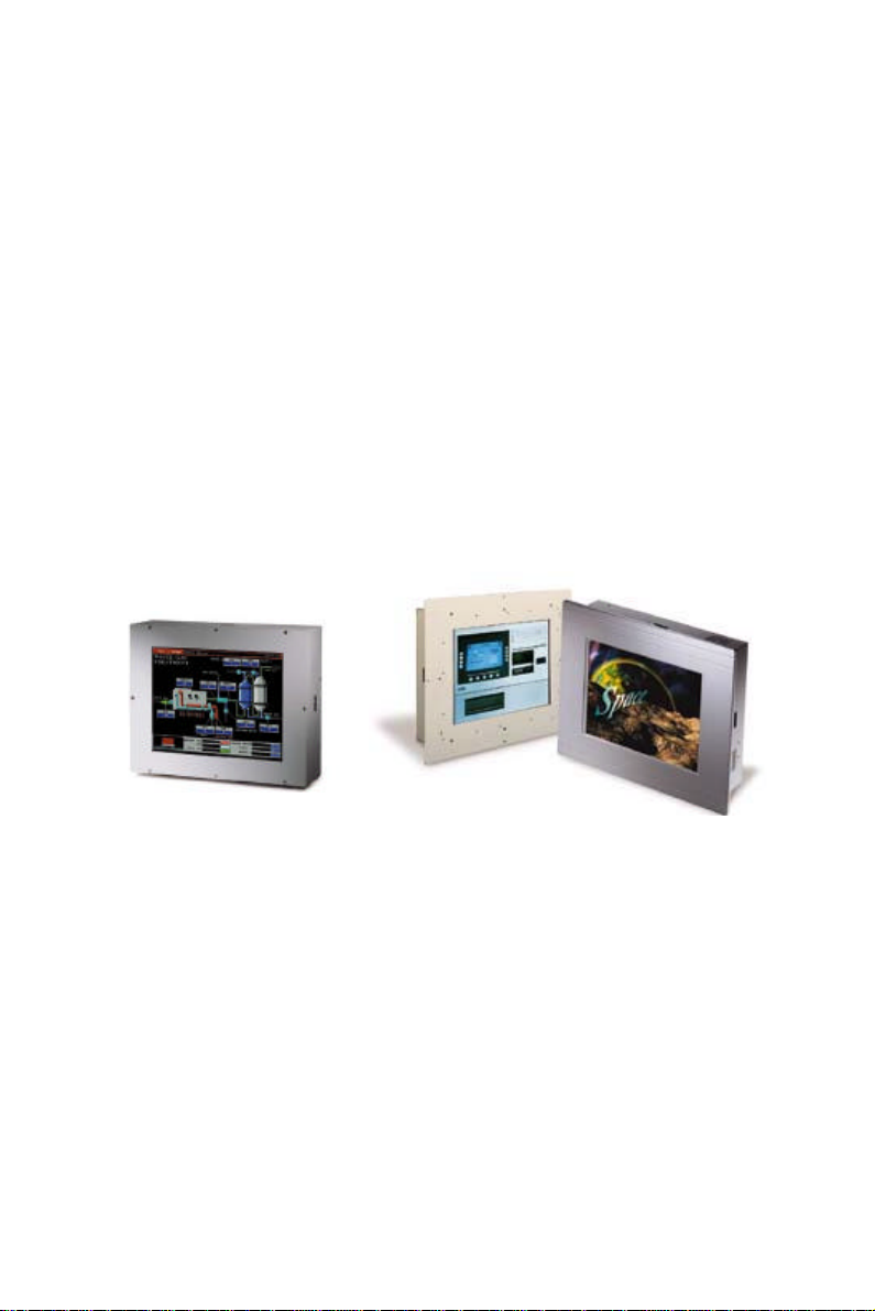
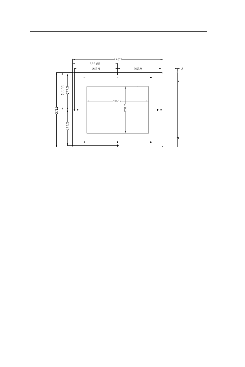
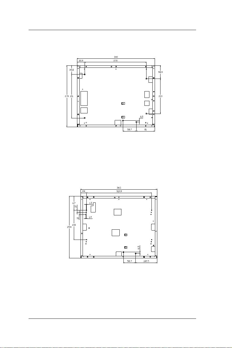
1.4. Dimensions
The OPEN (660) system chassis size is shown below;
Dimension: OPEN 120 (unit: mm)
OPEN (660) 120/140/150
Dimension: OPEN 140 (unit: mm)
1-9
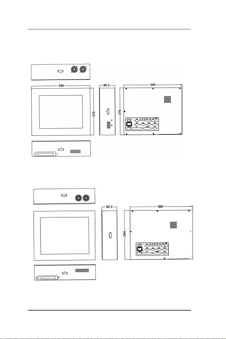
Page 20
User Manual version 2.1
Dimension: OPEN 150 (unit: mm)
1-10
OPEN (660) 120/140/150
Page 21
User Manual version 2.1
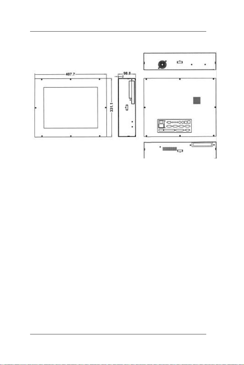
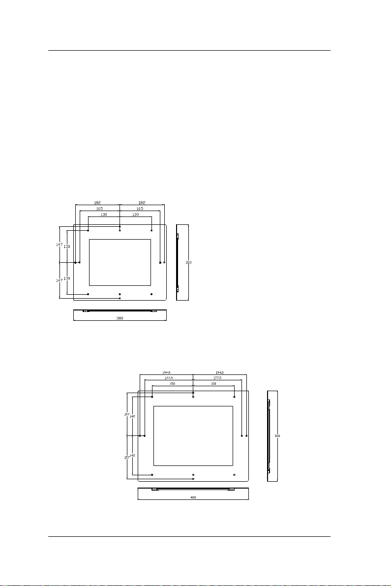
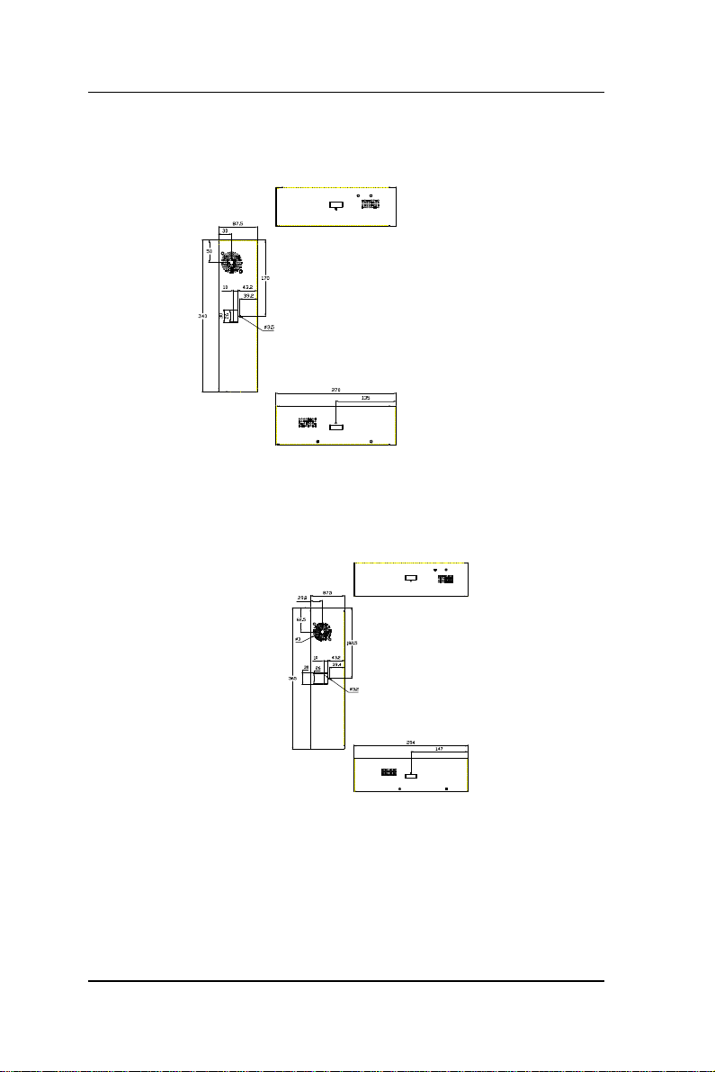
1.5. Optional Modules & Accessories
1.5.1. Touchscreen Module
The OPEN (660) system features a touchscreen
module for mounting a touchscreen for keyboardless
operation. The special designed touchscreen module
can firmly hold the touch panel and the LCD panel
together to prevent dust and water in. The
touchscreen module’s mechanism is shown below;
Dimension (unit: mm): OPEN 120 Touchscreen module
Dimension (unit: mm) : OPEN 140 touchscreen module
OPEN (660) 120/140/150
1-11
Page 22
User Manual version 2.1
Dimension (unit: mm) : OPEN 150 touchscreen module
Caution: The connection point of the touchscreen and
its cables is very fragile. Do not take the
touchscreen by dragging its cable or pull the
cables at any time; this may lead inaccurate
calibration or non-function to the
touchscreen.
1-12
OPEN (660) 120/140/150
Page 23

User Manual version 2.1
2. IDENTIFYING THE SYSTEM COMPONENTS
Before getting started, take a moment
to familiarize yourself with the different
parts and the I/O arrangement of the
OPEN (660) 120/140/150 I. Sections in
this chapter include the system’s
u Front view
u Side Views
u I/O outlets
OPEN (660) 120/140/150
2-13
Page 24
User Manual version 2.1
2.1. Front View
OPEN 120 front view
2-14
OPEN 140 front view
OPEN (660) 120/140/150
Page 25
2.2. Side Views
User Manual version 2.1
OPEN 120 side view
OPEN (660) 120/140/150
OPEN 140 side view
2-15
Page 26
User Manual version 2.1
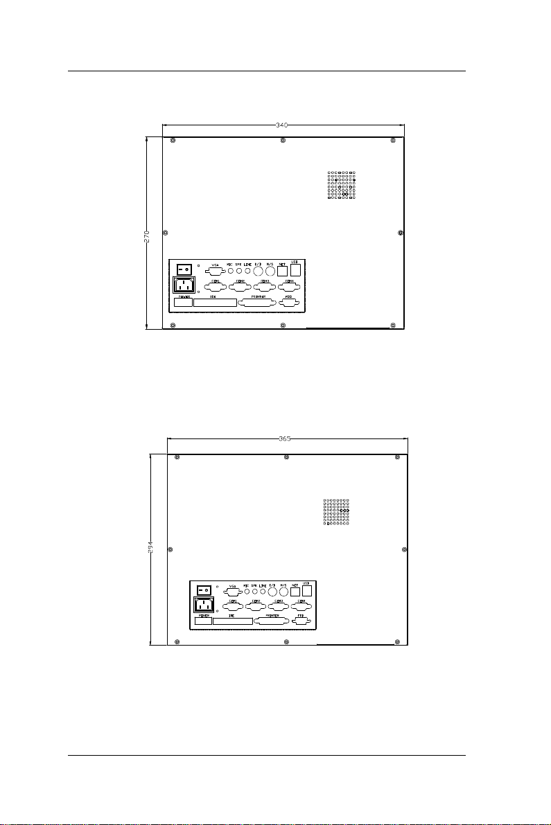
2.3. I/O Outlets
OPEN 120 I/O outlet
2-16
OPEN 140 I/O outlet
OPEN (660) 120/140/150
Page 27
User Manual version 2.1
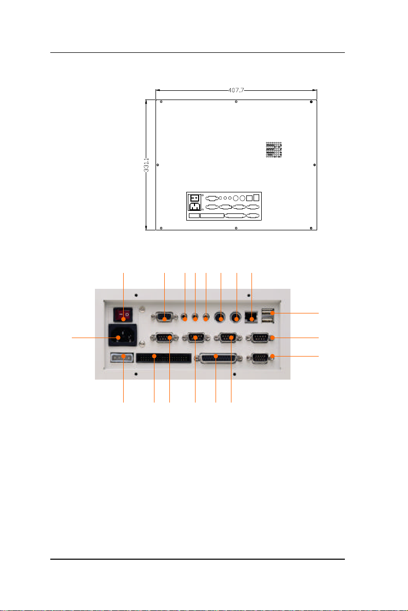
OPEN 150 I/O outlet
18 8 7 6 5 4 3 2
1
17
16 15 9 10 14 11
1. USB PORT 2. ETHERNET (RJ-45) 3. PS/2 MOUSE
4. PS/2 KB 5. LINE-IN 6. SPEAKER-OUT
7. MIC-IN 8. VGA PORT 9. COM 1
10. COM 2 11. COM 3 12. COM 4
13. EXTERNAL FDD 14. PRINTER PORT 15. EXTERNAL IDE
16. +5V/12V POWER 17. AC INLET 18. POWER SWITCH
OPEN (660) 120/140/150
12
13
2-17
Page 28
User Manual version 2.1
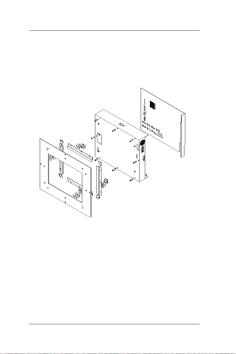
2.4. System Major Parts
The following diagram shows the system major parts that
make up the OPEN (660) 120/140/150 II.
2-18
OPEN (660) 120/140/150
Page 29

User Manual version 2.1
2.5. System Setup for the First-time Use
To set up the OPEN (660) system for the first-time use,
you should have the following items ready. The items are
either in the accessory box or available in any computer
stores.
u 110V or 220V power cord
u PS/2 or AT keyboard
u PS/2 or serial mouse
2.5.1. Installation Procedures
The OPEN (660) system can be powered either by an AC
electrical outlet (90 ~ 240V, 50 ~ 60Hz) or by DC power
source (9 ~ 132 VDC). If the system is to be powered up
by AC power, be sure to use the right power cord (110V or
220V) for connection.
1. Connect the female end of the power cord to the AC
inlet located at the rear side of the panel PC.
2. Connect the 3-pin male end of the power cord to an
electrical outlet.
3. Connect a PS/2 keyboard or an AT keyboard to
keyboard port. If you are using an AT keyboard, you
need an adapter (AT to PS/2 KB) for this connection.
4. Connect the PS/2 mouse to the PS/2 mouse port. If
you are using a serial mouse, it can be connected to
the COM port.
5. Power on the panel PC by switching the power switch
located at the rear cover.
OPEN (660) 120/140/150
2-19
Page 30

User Manual version 2.1
2.5.2. Running the BIOS Setup
If you are a commercial user, the OPEN (660)
120/140/150 should have been properly set up and
configured by your dealer. You may still find it necessary
to change the system configuration information. In this
case, you need to run the system’s BIOS setup program.
Under the following conditions, the CMOS settings are to
be changed;
1. The system is starting for the first time
2. The hardware devices attached to the OPEN (660)
system have been changed
3. The CMOS memory has lost power and the
configuration information has been erased.
The BIOS setup program is stored in ROM which can be
accessed by pressing <DEL> key on the keyboard
immediately when the system is powered on.
In order to retain the specified setup information when
the system power is turned off, the system setup
information is stored in a battery-backed CMOS RAM.
The battery is to ensure the settings will not be erased
when the computer is turned off or reset. When the
computer is powered on again, the system will read the
settings stored in the CMOS RAM and compare them to
the equipment check conducted during the power on self
test (POST). If any error or mismatch occurs, an error
message will be shown on the screen and the computer
will be prompted to run the setup program.
To change the BIOS setup, please refer to Chapter 7 for
more information.
2-20
OPEN (660) 120/140/150
Page 31

User Manual version 2.1
2.5.3. Operating System and Driver Installation
The OPEN (660) system is not equipped with an
operating system when delivered from the original
manufacturer. If you are a commercial user, the system
is likely to have been pre-installed proper operating
system and software drivers by your dealer or system
integrator.
If the system is not pre-installed with any system OS and
drivers or you intend to install your preferred ones, there
are several ways to load OS and software into the
system.
1. Via the external FDD or internal FDD
2. Via the external CD-ROM or internal CD-ROM
3. Via Ethernet: You can boot up the system via Ethernet
bootrom and download system OS or software from
the network.
Recent releases of operating systems always include
setup program which load automatically and guide you
through the installation. You can also refer to your OS
user manual for instructions on formatting or partitioning
the hard disk drive before any software installation.
The OPEN (660) system provides the following utility
drivers which are stored in the CD-ROM diskette or
utilities diskettes;
² Ethernet utilities
² VGA utilities
² Audio drivers
² Touchscreen drivers
OPEN (660) 120/140/150
2-21
Page 32

User Manual version 2.1
3-22
OPEN (660) 120/140/150
Page 33

User Manual version 2.1
3. MOUNTING OPTIONS
To OPEN (660) system is designed for
universal mounting to fit into different
system enclosures for various
environmental applications. This chapter
highlights the steps of different mounting
alternatives of the OPEN (660) system.
Sections include
u Different Front Panels
u Metal Fixtures
u Front Mounting
u Rear Mounting
u Panel Mounting
OPEN (660) 120/140/150
3-23
Page 34

User Manual version 2.1
3.1. Different Front Bezels
The standard OPEN (660) systems provide 3 kinds of
front bezel for different environmental applications.
3.1.1. OPEN (660) system with Small Bezel
The OPEN (660) 120/140/150 S is OPEN (660) system
with small bezel. The front bezel size is identical to the
computer’s chassis size.
Front bezel size (Small bezel)
OPEN (660) 120S: 340*270 mm
OPEN (660) 140S: 365*294 mm
OPEN (660) 150S: 408*331 mm
This type of frame is mainly designed for KIOSK
integration when the KIOSK enclosure is not of flat
surface and does not allow a big frame computer. When
integrating the OPEN (660) S system into the KIOSK
enclosure, the integrator may need to design special
metal fixtures per the enclosure’s specific mechanism in
order to fix the OPEN (660) system to the enclosure.
3-24
OPEN (660) 120/140/150
Page 35

User Manual version 2.1
3.1.2. OPEN (660) system with Big Bezel
The OPEN (660) 120/140/150 B is OPEN (660) system
with big bezel. The front bezel size is larger than the
computer’s chassis size.
Front bezel size (Big panel)
OPEN (660) 120B: 380*310 mm
OPEN (660) 140B: 405*330 mm
OPEN (660) 150B: 448*371 mm
The type of frame is mainly designed for panel mounting
or for KIOSK integration when the KIOSK enclosure is of
flat surface and allows the computer to be fixed to the
KIOSK enclosure directly. When integrating the OPEN
(660) B system into the KIOSK enclosure, the integrator
can either use the provided metal fixture or design
special metal fixtures per the enclosure’s specific
mechanism in order to fix the OPEN (660) system to the
enclosure.
OPEN (660) 120/140/150
3-25
Page 36

User Manual version 2.1
Front bezel size (Aluminum frame)
3.1.3. Aluminum Alloy Frame
The OPEN (660) 120/140/150 A is OPEN (660) system
with an aluminum alloy frame. The aluminum alloy frame
is mainly designed for panel mounting. It not only
strengthens the system’s framework but also beautifies
the system outlook when the system is panel mounted.
OPEN (660) 120A: 380*310 mm
OPEN (660) 140A: 405*330 mm
OPEN (660) 150A: 448*371 mm
3-26
OPEN (660) 120/140/150
Page 37

User Manual version 2.1
3.2. Metal Fixtures
The OPEN (660) system provides 2 sets of metal fixture
for system mounting. In most occasions, special metal
fixtures need to be designed to mount the OPEN (660)
system to different system enclosures.
3.2.1. Metal Fixture A
A set of metal fixture A is provided to fix the system
enclosure and the computer chassis together. To use the
metal fixtures, follow the instructions below;
1. Use the provided screw to fix the “a” side of the metal
fixture to the concave opening of the 4 sides (upper,
down, right & left) of the computer chassis.
2. Fix the “b” side of the metal fixture to the frame of the
touchscreen module with provided screws. If no
touchscreen module is used, then fix it to the system
enclosure. The metal fixture comes with fixing holes
on all sides to be fixed from all directions.
OPEN (660) 120/140/150
3-27
Page 38

User Manual version 2.1
22.7
25
25
22.7
3.2.2. Metal Fixture B
Another set of metal fixture B is also provided to fix the
system enclosure and the computer chassis together.
The metal fixture B is mainly used in panel mounting
application, i.e. when the touchscreen is mounted
outside of the system enclosure while the computer itself
is mounted from inside. Use the provided screws to
firmly fix the system enclosure between the touchscreen
module and the computer chassis with metal fixture B.
3-28
OPEN (660) 120/140/150
Page 39

User Manual version 2.1
Touchscreen
3.3. Front Mounting
The OPEN system can be mounted to the system
enclosure from the enclosure’s front side. Two conditions
are introduced in this section.
3.3.1. Front Mounting with Touchscreen Module
If the OPEN system comes with
a touchscreen module, to
mount the computer to the
system enclosure from the front
side, follow the steps below;
1. Cut a window of the same size of
the OPEN system’s panel display
on the system enclosure and
make necessary fixed holes on it.
2. Before inserting the OPEN system
into the system enclosure, make
sure all the hardware jumpers
and necessary software are
installed.
3. Glue the cut window verge of
the system enclosure with
close cell tape to prevent
dust and water in.
4. Fix the OPEN system to the
system enclosure with
provided screws. Be sure to
align the cut window to the
OPEN system’s flat panel
display.
System enclosure
module
Fixture A
Note: The front mounting is the easiest mounting
methods. However, this mounting method will
leave the screws seen on the system enclosure. It
is suggested to use plastic covering or paint to doll
up the system appearance.
OPEN (660) 120/140/150
3-29
Page 40

User Manual version 2.1
System enclosure
3.3.2. Front Mounting without Touchscreen Module
If the application does not need the installation of the
touchscreen module, then there are two methods to
mount the OPEN system from the system enclosure’s
front side.
Method 1 with bronze stick
1. Cut a window of the same size of
the OPEN system’s flat panel
display on the system enclosure
and make necessary fixed holes
on it.
2. Before inserting the OPEN system
into the system enclosure, make
sure all the hardware jumpers
and necessary software are
installed.
3. Get a glass or acrylic transparent
piece of the size slighter larger
than the cut window. Glue the
transparent piece to the cut
window verge of the system
enclosure to prevent dust and
water in. It is suggested that the
crevice between the LCD panel
display and transparent piece not
to exceed 1mm.
4. Fix the OPEN system to the
system enclosure with provided
bronze sticks. Be sure to align
the cut window to the OPEN
system's flat panel display.
Note: The suggested thickness of the glass or acrylic
used for the transparent piece is between 2mm
to 5mm depending on the bronze stick height. If
the system is to be put in public area, it is
suggested to use resilient glass or acrylic to
protect the LCD display.
Bronze stick
3-30
OPEN (660) 120/140/150
Page 41

User Manual version 2.1
Method 2 with metal fixture A
1. Cut a window of the same size of the OPEN
120/140/150’s flat panel display on the system
enclosure and make necessary fixed holes on it.
2. Before inserting the OPEN system into the system
enclosure, make sure all the hardware jumpers and
necessary software are installed.
3. Get a glass or acrylic transparent piece of the size
slighter larger than the cut window. Glue the
transparent piece to the cut window verge of the
system enclosure to prevent dust and water in. It is
suggested that the crevice between the LCD panel
display and transparent piece not to exceed 1mm.
4. Fix the OPEN system to the cut window of the system
enclosure with the provided metal fixture A (refer to
Sec. 1.4.2). Be sure to align the cut window to the
OPEN system’s flat panel display.
Note: Method 1 is easier than method 2. If the system is
to be exposed in an environment with constant vibration,
even slight vibration, then method 2 is recommended.
Fixture on system enclosure
System enclosure
Fixture A
OPEN (660) 120/140/150
System enclosure
Fixture A
3-31
Page 42

User Manual version 2.1
3.4. Rear Mounting
To fit into special environmental applications, the OPEN
system can be also mounted to the system enclosure
from the enclosure panel’s rear side. Two conditions are
introduced in this section.
3-32
OPEN (660) 120/140/150
Page 43

User Manual version 2.1
System enclosure
module
3.4.1. Fixing on the System Enclosure’s front panel
Refer to the following figure and follow the steps below.
1. Cut a window of the same size of the
OPEN system’s panel display on the
system enclosure. The system
enclosure should come with some
brackets. To make the brackets,
please refer to the diagram of the
dimension and fixing holes of the
OPEN system in Sec. 1.4. Fix the
brackets on the 4 sides of the
enclosure’s front panel. The brackets
are used to fix the OPEN system and
the system enclosure together later.
The OPEN system can either be fixed
to brackets of the system enclosure
by screws or by soldering.
2. Before inserting the OPEN system
into the system enclosure, make sure
all the hardware jumpers and
necessary software are installed.
3. Use metal fixture A to fix the
touchscreen module to the OPEN
system chassis. If no touchscreen is
used, then put a glass or acrylic piece
instead. The touchscreen module
frame is still needed to fix the
transparent piece to the computer.
4. Screw the brackets on the system
enclosure and the metal fixture A on
the OPEN system chassis together
with provided screws.
Note: The suggested thickness of the glass or acrylic used
for the transparent piece is between 2mm to 5mm
depending on the bronze stick height. If the system
is to be put in public area, it is suggested to use
resilient glass or acrylic to protect the LCD display.
System enclosure
Bracket on the
Fixture A
Touchscreen
OPEN (660) 120/140/150
3-33
Page 44

User Manual version 2.1
system enclosure
3.4.2. Fixing on the System Enclosure’s back panel
1. Cut a window of the same size of
the OPEN system’s panel display
on the system enclosure. The
system enclosure should come
with some brackets. To make the
brackets, please refer to the
diagram of the dimension and
fixing holes of the OPEN system in
Sec. 1.4. Fix the brackets on the 4
sides of the enclosure’s back panel.
The brackets are used to fix the
OPEN system and the system
enclosure together later. The
OPEN system can either be fixed
to brackets of the system
enclosure by screws or by
soldering.
2. Before inserting the OPEN system
into the system enclosure, make sure
all the hardware jumpers and
necessary software are installed.
3. Use metal fixture A to fix the
touchscreen module to the OPEN
system chassis. If no touchscreen is
used, then put a glass or acrylic piece
instead. The touchscreen module
frame is still needed to fix the
transparent piece to the computer.
4. Screw the brackets on the system
enclosure and the metal fixture A on
the OPEN system chassis together with
provided screws.
5. Note: The suggested thickness of the glass or
acrylic used for the transparent piece is between
2mm to 5mm depending on the bronze stick height.
If the system is to be put in public area, it is
suggested to use resilient glass or acrylic to protect
the LCD display.
Touchscreen module
Fixture A
System enclosure
Fixture on the
3-34
OPEN (660) 120/140/150
Page 45

User Manual version 2.1
If the system enclosure is not limited in thickness, then to
mount the OPEN system on the system enclosure’s front
panel is recommended for easy installation and
maintenance. However, if the system enclosure is limited
in space, then it is suggested to mount the OPEN system
on the system enclosure’s back panel to increase the
installation yield rate.
OPEN (660) 120/140/150
3-35
Page 46

User Manual version 2.1
3.5. Panel Mounting
The panel mounting is the easiest method among all
mounting alternatives. However, this will expose the
aluminum alloy frame or the touchscreen module frame
outside of the system enclosure unless a special frame is
designed to cover it. Follow the instructions below for
panel mounting.
1. Cut a window of the same size of
the OPEN system panel display
on the system enclosure.
2. Before inserting the OPEN
system into the system
enclosure, make sure all the
Aluminum
hardware jumpers and
necessary software are
installed.
3. Assemble the aluminum alloy
frame or the touchscreen
module to the OPEN system
first. (The aluminum alloy
frame can also be used to fix
the touchscreen module.)
4. Insert the OPEN system into
to the cut window of the
system enclosure from
outside. At this moment, the
OPEN system is not fixed to
the system enclosure yet.
5. Fix the metal fixture B on the 4 sides
of the OPEN system chassis (upper,
down, right and left).
6. Use the provided screws to firmly fix the system
enclosure between the touchscreen module and the
computer chassis with metal fixture B.
System enclosure
Fixture B
alloy
frame
3-36
OPEN (660) 120/140/150
Page 47

User Manual version 2.1
4. SYSTEM HARDWARE INSTALLATION
This chapter overviews the installation of
the OPEN (660) II system internal
components and devices. Sections
include:
u Installing the CPU
u Installing the SDRAM
u Installing the HDD
u Installing the FDD
u Installing the CD-ROM drive
u Expansion slot
OPEN (660) 120/140/150
4-37
Page 48

User Manual version 2.1
The OPEN (660) 120/140/150 II consists of a Celeron/
Pentium® III embedded little board with an adequate CPU
and relevant SDRAM on it. The system control board and
other internal devices such as expansion card, HDD and
power supply are already housed in a plastic rear cover.
The system’s performance depends on the installed CPU
and the capacity of the system memory and hard disk
drive. In some circumstances, you might intend to
upgrade or maintain the system. By removing the rear
cover and the metal covers, the internal components
such as CPU, SDRAM, HDD and power supply can be
easily accessed for maintenance and upgrade.
4-38
OPEN (660) 120/140/150
Page 49

User Manual version 2.1
4.1. Installing the CPU
The OPEN (660) 120/140/150 II system control board
can adapt Intel Celeron and Pentium III CPU. It can
support Intel Socket 370 CPU from Celeron
PPGA/FCPGA/66MHzz to Pentium® III FCPGA/100MHz
(Intel 440BX).
The system controller provides one 370-pin socket
(Socket 370). The CPU must come with a CPU fan to
avoid overheating. The Celeron CPU and P III CPU will
request different kinds of CPU fans due the difference on
the CPUs’ mechanism. Wrong fans might lead to
overheating for the entire system. To install a CPU or
upgrade a new CPU, follow the instructions below.
1. If there is an existing CPU on the socket, remove the
CPU first by pulling the lever out a little and raising it,
then lifting out the existing CPU from the socket.
2. To insert the CPU into the socket, the notch on the
corner of the CPU (the corner with white dot) should
point toward the end of the socket lever. If the
insertion of the CPU to the socket is not easy, check
whether the CPU pins correspond with the holes on
the socket.
3. After insert the CPU into the socket, pull the lever
down to make sure the CPU is in place.
4. The CPU cooling fan comes with a 3-pin power cable.
Connect the power cable to the 3-pin power
connector on the motherboard.
5. There are two small white clips on the CPU sockets.
Make sure the cooling CPU fan clips click into place.
®
OPEN (660) 120/140/150
CPU socket
3-pin CPU fan
power connector
FIGURE 5-5
4-39
Page 50

User Manual version 2.1
4.2. Installing the SDRAM Memory Module
The OPEN (660) 120/140/150 II system control board
provides 1 x 168-pin DIMM socket, able to support
SDRAM memory from 32MB up to 256MB. To install the
memory module, follow the instructions below;
1. Detach and remove the rear cover.
2. Find the 168 pin DIMM socket on the motherboard
3. There are two white eject levers at each end of the
DIMM socket. Push them outward until they
separate from the two vertical posts.
4. Holding the memory module with the notch on the
upper right corner, then insert the memory module
into the DIMM socket at 90° angle.
5. Push the two eject levers toward the vertical posts
until they click into place. The memory module is
now upright.
The system is able to auto detect the new memory size
and there is no need to change the system configuration
after installation.
Make sure that the memory module you are using can
handle the specified SDRAM MHz. Inadequate memory
module will make the computer unable to boot up.
4-40
OPEN (660) 120/140/150
Page 51

User Manual version 2.1
4.3. Installing the HDD
4.3.1. OPEN (660) 120/140 2.5" HDD Installation
The OPEN (660) 120/140 provides enough space to build
in a 2.5” hard disk drive in the computer chassis. If the
user intends to attach a 2.5” hard disk or remove the
existing device for repair or for a higher-capacity one, the
following figure shows you the way to install an internal
HDD.
1. Detach and remove the rear cover. The HDD module is
located at the side of the system compartment
2. Remove the whole HDD module from the system
compartment.
3. Insert the 4 provided rubber cushions to the HDD
bracket first.
4. Glue the mylar insulator to the Hard disk drive
5. Install the 2.5” HDD to the HDD bracket with screws.
6. Then, insert the whole unit to the system
compartment.
7. Use the provided 44-pin IDE cable to connect the hard
disk drive to the system IDE connector. Match pin 1 of
the hard disk drive and pin 1 of the cable.
OPEN (660) 120/140/150
4-41
Page 52

User Manual version 2.1
4.3.2. OPEN (660) 150 3.5" HDD Installation
The OPEN (660) 150 provides enough space to build in a
3.5” hard disk drive in the computer chassis. If the user
intends to attach a 3.5” hard disk or remove the existing
device for repair or for a higher-capacity one, the
following figure shows you the way to install an internal
HDD.
1. Detach and remove the rear cover.
2. Remove the CD-ROM/FDD module.
3. Take out the FDD/IDE board
4. Remove the whole HDD module.
5. Install the 3.5” HDD to the HDD bracket with screws.
6. Then, insert the whole unit to the system
compartment
7. Insert the CD-ROM/FDD/HDD board back again.
8. The are two IDE cables, one 44-44 pin IDE cable and
the other 40-40 pin cable. The 44 pin cable is used to
connect the 44 pin IDE connector on the IDE/FDD
board to the PC 660A2 primary IDE connector. Then,
Use the provided 40-pin IDE cable to connect the HDD
to the IDE connector on the FDD/IDE board. Match pin
1 of the HDD and pin 1 of the cable.
9. Make sure the CD-ROM cable, 16 pin FDD cable, 4 pin
audio cable and 5V power cable is properly connected
to all the connectors on the FDD/IDE board (Refer to
Sec. 4.2.2 for detailed figure for the FDD/IDE board).
4-42
HDD bracket
FDD/IDE board
OPEN (660) 120/140/150
Page 53

User Manual version 2.1
FDD cable
4.4. Installing the FDD
The OPEN (660) 120/140/150 II can connect to an
external floppy disk drive.
4.4.1. External FDD connection
1. Use the provided 15-34 pin FDD cable to connect to
the system's 15-pin FDD D-sub connector located at
the rear side of the cover.
2. Connect the other end of the FDD cable to a standard
3.5” FDD. Match pin 1 of the floppy disk drive and pin
1 of the cable.
3. Use the provided FDD/IDE power cable to connect
the 4 pin FDD power connector to the system 4-pin
power connector located at the left bottom side of the
chassis.
OPEN (660) 120/140/150
4-43
Page 54

User Manual version 2.1
16 pin FDD connector
4.4.2. Internal FDD installation for OPEN 150
Aside from connecting to an external FDD, the OPEN (660)
150 can also accommodate an internal slim type FDD,
depending on the system requirement. The floppy disk
drive used in the OPEN 150 II is a slim type FDD widely
used in notebook computers. To install the floppy disk
drive to the OPEN 150, refer to the following steps below:
1. Detach and remove the rear cover.
2. There is an FDD/CD-ROM bracket holding the FDD.
Remove the bracket. Place a slim type floppy disk
drive on the bracket. Fix the FDD on the bracket with
the 4 screws.
3. Use a 26 pin flat FDD cable to connect the FDD to the
FDD connector on the FDD/IDE board.
4. Make sure the 16 pin FDD cable, 4 pin audio cable and
5V power cable is properly connected from the OPEN
(660) to all the connectors on the FDD/IDE board.
50 pin CD-ROM
connector
4-44
44 pin IDE
connector
26 pin FDD connector
40 pin HDD
connector
OPEN (660) 120/140/150
2 pin 5V power
connector
4 pin audio power
connector
FDD/IDE board for OPEN
Page 55

User Manual version 2.1
4.5. Installing the CD-ROM drive
The OPEN 120/140/150 II can connect to an external
CD-ROM via the system's external IDE connector.
4.5.1. External CD-ROM connection
1. Use the provided 40 pin IDE cable to connect to the
system IDE connector located at the rear side of the
cover.
2. Connect the other end of the IDE cable to a standard
CD-ROM drive
3. Use the provided FDD/IDE power cable to connect the
4 pin IDE power connector to the system 4-pin power
connector located at the left bottom side of the
chassis.
OPEN (660) 120/140/150
4-45
Page 56

User Manual version 2.1
4.5.2. Installing Internal CD-ROM for OPEN 150
Aside from connecting to an external CD-ROM, the OPEN
150 can also accommodate an internal slim type CD-ROM,
depending on the system requirement. The CD-ROM
drive used in the OPEN 150 II is not the common 5.25”
CD-ROM drive seen in computer stores. Rather, it is a
slim type CD-ROM widely used in notebook computers.
To install a compact CD-ROM to the OPEN 150 system,
refer to the following figure and follow the steps below:
1. Detach and remove the rear cover.
2. There is an FDD/CD-ROM bracket holding the CD-
ROM.
3. Remove the bracket from the system compartment.
4. Fix the slim type CD-ROM drive to the small CD-ROM
metal bracket with 2 screws. Please note that the 2
screws need to be incased with 2 plastic washers.
5. Insert the CD-ROM module to FDD/CD-ROM bracket
and fix them with 4 screws.
6. Fix the whole unit to the system compartment
7. Use a 50 pin CD-ROM cable to connect the CD-ROM
to the 50 pin IDE connector on the FDD/CD-ROM
board.
8. Make sure the 4 pin audio cable and 5V power cable is
properly connected from the PC 660A2 to all the
connectors on the FDD/IDE board (Also refer to the
figure on Sec. 4.2.2).
4-46
OPEN (660) 120/140/150
Page 57

User Manual version 2.1
4.6. Expansion Slot
The OPEN system provides a free PCI/ISA expansion slot.
Via the specially designed riser card, the system can
accommodate either an ISA or PCI expansion device.
Due to the space limitation, only one PCI or ISA device
can be inserted in the expansion at a given time. Also
due to the internal space limitation, only a compact
expansion card can be inserted. The expansion card size
can not exceed 160*120 mm (L*W). To use the PCI or
ISA expansion, follow these instructions below;
1. Unscrew the metal slip located inside the expansion
outlet.
2. Plug either an ISA or PCI card into the ISA or PCI slot
on the riser card and fix the expansion card by
screwing it to the metal front compartment. All the
connectors of the expansion card will come out from
the expansion outlet on the bottom side of the chassis
for further cable connection.
However, for special environmental applications, the
number of expansion slots is customizable.
OPEN (660) 120/140/150
4-47
Page 58

User Manual version 2.1
5-48
OPEN (660) 120/140/150
Page 59

User Manual version 2.1
5. I/O CONNECTION
This chapter describes the OPEN (660)
system I/O ports and how to use the I/O
interface to connect to external devices.
OPEN (660) 120/140/150
5-49
Page 60

User Manual version 2.1
The user can use the I/O interfaces located at the rear
side of the chassis to connect external peripheral devices,
such as a mouse, a keyboard, a monitor, serial devices or
parallel printer…etc. Before any connection, make sure
that the computer and the peripheral devices are turned
off.
5.1. VGA Interface
The OPEN (660) 120/140/150 II has a 15-pin analog RGB
connector located at the rear side of the chassis. It can
support its own LCD display and an expansion CRT or
analog monitor at the same time. However, as the LCD
panel used in the 14.1” & 15.1” system (OPEN (660)
140/150) is of the resolution of 1024 x 768 and in 12.1”
system (OPEN (660) 120) is 800 x 600, therefore, to
support a CRT or analog monitor simultaneously, the
monitor’s VGA resolution has to be set to 800 x 600 for
OPEN (660) 120 and 1024 x 768 for OPEN (660) 140/150.
The connection to an analog monitor is an easy plug-in of
the VGA D-SUB 15-pin connector to the RGB interface.
There is some application software that is to be executed
in 800*600 resolution. When the software is running
under OPEN (660) 140/150, only part of the screen will
show on the LCD display. If the application has to run in
full screen, you need to update the system VGA drivers
with an auto expansion utility. However, due to
resolution limitation, the text mode will look slightly
distorted.
5-50
OPEN (660) 120/140/150
Page 61

User Manual version 2.1
5.2. COM Ports x 4
The OPEN (660) 120/140/150 (+) II features with four
onboard COM ports located at the rear side of the chassis,
ready to connect to a wide range of serial devices. COM1,
COM3 and COM4 are RS-232 and COM2 is RS-232/485,
selected via jumper setting. Each COM port is with
+5V/+12V power capabilities on pin 9, providing easy
accommodation to a broad range of serial devices.
The COM port 5V/12 power is selected via jumper setting
on the I/O board.
Please refer to the following for the 5V/12 power selection.
J8
5 3 1
6
COM1
J7
4 2
5 3 1
6 4 2
COM2
5 3 1
6 4 2
J10J9 J12J11
5 3 1
5 3 1
6 4 2
6 4 2
COM4COM3 COM1
5 3 1
6 4 2
COM2
5 3 1
5 3 1
6 4 2
6 4 2
COM3 COM4
J14J13
5 3 1
6 4 2
+5V+12VRI
5 3 1
6 4 2
(Default)
135
4 26
RI(default) +12V +5V
5 3 1
6 4 2
5 3 1
6 4 2
5 3 1
6 4 2
OPEN (660) 120/140/150
COM1 COM3
Pin 1
J11
Pin 9
J7
J13
J9
COM4
J14
J10
COM2
J12
J8
Pin# COM1 COM2 COM3 COM4
#1 J11 J12 J13 J14
#9 J7 J8 J9 J10
5-51
Page 62

User Manual version 2.1
If a touchscreen module is installed, for factory default
setting, its controller will occupy COM3.
COM1 to COM4 are all D-SUB 9-pin connectors. To
connect to any serial device; follow the procedures
below;
1. Turn off the OPEN system and the serial devices.
2. Attach the interface cable of the serial device to the
9-pin D-SUB serial connector. Be sure to fasten the
retaining screws.
3. Turn on the computer and the attached serial devices.
4. Refer to the serial device’s manual for instruction to
configure the operation environment to recognize the
new attached devices.
5. If the serial device needs specified IRQ or address, you
may need to run the CMOS setup to change the
hardware device setup.
If the COM2 is to be set to RS-485 for long distance
transmission, the related onboard jumpers have to be set
correctly first. Refer to section 6.2.1.2 for the RS232/485 jumper settings and Appendix D for RS-485
programming.
5-52
OPEN (660) 120/140/150
Page 63

User Manual version 2.1
5.3. Parallel Port
The OPEN (660) system can support the latest EPP and
ECP parallel port protocols. It can be used to connect to a
wide array of printers, ZIP drive, parallel scanner and any
other parallel devices. The printer interface on the OPEN
(660) system is a 25-pin female D-SUB connector located
on the bottom side. To connect any parallel device, just
plug in the male connector of the parallel device to the
25-pin female D-SUB connector.
5.4. 100/10 Base-T Ethernet (RJ-45)
The OPEN (660) system provides an NE2000 compatible
Ethernet (RJ-45) interface. For network connection, just
plug in one end of cable of a 100/10 Base-T hub to the
computer’s RJ-45 phone jack. The pin assignment of the
RJ-45 is listed as follow;
1
2 3 4 5 6 7
RJ-45
8
RJ-45 Connector Pin Assignment
Pin Description
1
2
3
6
others
Tx+ (data transmission positive)
Tx- (data transmission negative)
Rx+ (data reception positive)
Rx- (data reception negative)
No use
OPEN (660) 120/140/150
5-53
Page 64

User Manual version 2.1
5.5. USB Ports
The OPEN (660) system also provides two USB ports to
connect to external USB devices. Before connecting to
the USB devices, remember to install the device driver
first.
5.6. Audio Interface
The audio interface contains three jacks, microphone-in,
line-in and speaker-out. The microphone-in jack is used
to record sound or voice by connecting to an external
microphone. The line-in jack is used to input audio from
an external audio device such as a CD player, tape
recorder or a radio. The speaker-out jack is to output the
audio to external devices such s speakers or earphones.
The audio device can be directly attached to the jacks.
Please note that the audio driver has to be installed first
before connecting to any audio device.
5-54
OPEN (660) 120/140/150
Page 65

User Manual version 2.1
1
2
3
4
5
6
7
8
9
1
0
5.7. External FDD (DB-15)
The OPEN (660) 120/140 II does not build in any floppy
disk drive into the main system. Rather, it provides a
FDD interface located at the rear panel. The OPEN (660)
150 can either use an internal floppy disk drive or to
external type. When the OPEN (660) system is using
external floppy disk drive, an external FDD cable is
provided to connect a standard 3.5” FDD to the system
for system O/S and application software installation. Its
pin position and pin assignment are listed as follows.
Pin # Signal Pin # Signal
1 DELSEL 9 -WD
2 -INDEX 10 -STEP
3 -MTR1 11 -RD
4 -DVR1 12 -HDSEL
5 -DIR 13 -DSKCHG
6 -WP 14 +5V
7 -TRKO 15 +12V
8 -WG
11
12
13
The OPEN (660) system is equipped with a
+5V/12V DC-out connector to provide 5V
power to drive the external floppy disk
drive. Use the provided FDD power cable
to connect the floppy drive to the 5V DCout connector when an external floppy
drive is attached to the system.
OPEN (660) 120/140/150
5-55
14
15
Page 66

User Manual version 2.1
5.8. +5V/12V DC-Out
The OPEN (660) system provides a +5V/12V DC-out
connector. It is used to provide necessary power source
for some external devices. For example, if an external
floppy disk drive is attached to the system, it will need
+5V power source from the system. A power cable for the
external floppy disk drive is already provided for this
connection. For other devices, you might need to make
your own power cable for the connection.
5.9. PS/2 Keyboard interface
The OPEN (660) system provides a standard PS/2
keyboard connector located at the rear panel. If the user
would like to use AT keyboard, then an adapter to
connect the PS/2 KB to AT KB is needed.
5.10. PS/2 Mouse
The OPEN (660) system has one PS/2 mouse connector
located at the right side. A simple plug-in will make the
connection.
5.11. AC/DC Inlet/Power Switch
For OPEN (660) system AC system, it can operate in the
input range from 90 ~ 240 volts, 50 ~ 60 Hz). For DC
system, the input range is from 9 ~ 132VDC.
5-56
OPEN (660) 120/140/150
Page 67

User Manual version 2.1
6. SYSTEM CONTROL BOARD
The system controller used in the OPEN (660)
system is a Celeron/Pentium® III multimedia
embedded little board, PC 660A3. This
chapter provides detail introduction of the
system engine.
OPEN (660) 120/140/150
6-57
Page 68

User Manual version 2.1
6.1. Introduction
This section provides background information and detail
specification on the OPEN (660) 120/140/150 II system
engine, PC 660A3. Sections include:
² General Information
² Features
² Specification
² Board placement & Dimension
6.1.1. General Information
The PC 660A3 is an Intel Celeron/ Pentium® III (Socket
370) multimedia mini board. Compact in size and with its
highly integrated multimedia and networking functions,
the PC 660A3 is the most powerful PC engine to build any
small footprint all-in-one PC system for integration into
any space-constricted embedded applications. Highly
integrated, the PC 660A3 can adapt Intel Celeron
(66MHz) and P III (100MHz) CPU. Onboard features
include super I/Os, XGA, LCD interface, IrDA, 10/100
Base-T Ethernet and audio functions. The full PC
functionality coupled with its multi-I/Os stand ready to
accommodate a wide range of PC peripherals. Special
industrial feature not commonly seen in commercial
systems such as watchdog timer makes the PC 660A3 the
best choice for the operation in any hostile environments.
Fully configurable and with its modular design, the PC
660A3 is an ideal platform for any consumer computing
applications where space is a premium.
6-58
OPEN (660) 120/140/150
Page 69

User Manual version 2.1
6.1.2. Features
u Compact profile for small-footprint system
u All-in-one design gets rid of compatibility and
reliability problem that go with commercial
motherboard
u Highly integrated design simplifies system integration
and reduces system cost
u Multi-I/O design for accommodation of many PC
peripherals
u Highly integrated multimedia functions
u High resolution for multimedia application
u Full networking and IrDA functions for convenient
data transmission
u Modular design makes customization easy
u Providing PCI/ISA expansion slot for system future
expansion
u Rugged industrial-grade construction allows system
operation in any hostile environment
u Long product life cycle
OPEN (660) 120/140/150
6-59
Page 70

User Manual version 2.1
6.1.3. Specifications
PC 660A3: Multimedia Intel Celeron/Pentium® III
Embedded Mini Board with XGA, Flat panel,
Ethernet & Audio Interface
u CPU: Intel Celeron/Pentium® III (Socket 370)
− Intel Celeron® PPGA/FCPGA/66MHzz
− Intel Pentium® III FCPGA/100MHz
u System Chipset: Intel 440BX or the equivalent
chipset
u System BIOS: Award PnP Flash BIOS
u System Memory: Equipped with one DIMM
socket to support (32MB, 64MB, 128MB, 256MB)
168-pin 3.3V SDRAM SPD (Special Presence
Detect).
u CPU built-in L2 Cache: Onchip 128KB Pipeline
Burst Level 2 cache in the Socket 370 cartridge.
u Flash Disk: Support M-Systems DiskOnChip
up to 144MB.
u Standard I/O
• Serial ports x 4: RS-232 x 3, RS-232/485 x 1
(COM2), jumper selectable
• Parallel port x 1: Support SPP/EPP/ECP
• Enhanced IDE Interface x 2: supports up to 4 IDE
devices
• FDD Interface x 1: supports up to 2 floppy disk
drives
• PS/2 Keyboard Interface x 1
• PS/2 Mouse Interface x 1
• USB Interface x 2
u TTL Digital I/O: Input x4, output x4
®
6-60
OPEN (660) 120/140/150
Page 71

User Manual version 2.1
u Watchdog Timer: 16 time intervals
u Green Function: APM 1.1 compliant
u Expansion Bus: PCI/ISA expansion slot x 1
u Ethernet Interface
• Ethernet chipset: RTL8139
• 10/100 Base-T Interface auto switch
• NE2000 compatible
u Display
• LCD/XGA chipset, C&T69000 with built-in 2MB
DRAM
• LCD/XGA chipset, C&T69030 with built-in 4MB
DRAM (optional)
u Audio Function
• Chipset: ESS ES1938S PnP audio controller
• Stereo sound: full-duplex, integrated 3D
audio
• Audio Interface: Line-In, Speaker-Out,
Mic-In and CD audio-in
• Power: accepts +12V source for
improved audio quality
u Infrared Transceiver:
Supports IrDA version 1.0 SIR protocol
u Power Requirement:
Single +5V operation @7A
+12V operation @1A
u Dimensions: 146 x 203 mm
Specifications are subject to change without notice.
OPEN (660) 120/140/150
6-61
Page 72

User Manual version 2.1
6.1.4. Board Placement & Dimension
The PC 660A3 dimension and layout is shown below;
1
CN6
JP10
Reserve
JP7 1-2 3-4
66M
100M
4 3
12
J3=ON
OFF
OFF
JP7
OFF
ON
JP4
CLR
D800D000
JP9
422 422
JP6
JP5
232 232
203.2
198.12
1
CN12
JP12,13
Reserve
FDC1
Celeron/Coppermine
J5=ON
Socket 370 CPU
JP13
JP12
DIMM1
JP8
CN4
CN3
422
JP3
232
1
3V5V
JP1
CN1
12V
IDE1
CN2
6-62
U4
CN10
CN9
J2
CN7
CN5CN8
135.89
146.05
OPEN (660) 120/140/150
Unit : mm
Page 73

User Manual version 2.1
6.2. Locating Jumpers & Connectors
The PC 660A3 is configured to match the needs of specific
application by proper jumper settings. The onboard
connectors link the PC 660A3 to external devices such as a
hard disk, a floppy disk or a printer. The following figure
helps you to locate all jumpers and connectors.
1
1
CN6
3V5V
JP1
CN1
12V
IDE1
1
CN12
JP12,13
Reserve
JP13
JP12
DIMM1
JP8
J5=ON
Celeron/Coppermine
Socket 370 CPU
JP10
Reserve
JP7 1-2 3-4
66M
100M
4 3
12
J3=ON
OFF
OFF
JP7
CN3
OFF
ON
JP4
CLR
FDC1
CN10
CN9
OPEN (660) 120/140/150
CN4
D800D000
JP6
422 422
232 232
JP5
JP9
422
JP3
232
CN2
U4
J2
CN7
CN5CN8
6-63
Page 74

User Manual version 2.1
6.2.1. Jumpers & Jumper Setting
The table below lists the function of each jumper. The
related jumper settings are shown in the coming
sections.
Jumper Description
JP1 LCD power setting
JP2 Reserved
JP4 CMOS clear
JP3 COM2 RS-232/485 selection
JP5 COM2 RS-232/485 selection
JP6 COM2 RS-232/485 selection
JP7 CPU frequency setting
JP9 DiskOnChip 2000 address setting
6-64
OPEN (660) 120/140/150
Page 75

User Manual version 2.1
6.2.1.1. DOC 2000 Address Setting (JP9)
D800
D000
Address D000~D7FF
6.2.1.2. COM 2 RS-232/485 Setting (JP3, 5, 6)
The PC 660A3 is a RS-232/485 serial port. JP3, JP5 and
JP6 determine the specific port type.
JP3
JP5
JP6
Address D800~DFFF
D800
D000
JP3
JP5
JP6
RS-232 mode RS-485 mode
The RS-485 is software programmable. Please refer to
APENDIX for the programming.
OPEN (660) 120/140/150
6-65
Page 76

User Manual version 2.1
6.2.1.3. CMOS Clear Setting (JP4)
Before setting “CMOS Clear”, remember to turn off the
power supply to avoid damaging the computer board.
After the setting, before turning on the power supply, set
the jumper back to “3.6V Battery on”.
JP4: CMOS Clear Setting
3.6V Battery On
CLR
default setting
6.2.1.4. LCD Power Setting (JP1)
5V 3.3V
Clear CMOS
default setting
CLR
6-66
OPEN (660) 120/140/150
Page 77

User Manual version 2.1
6.2.2. Connectors & Pin Assignment
The table below lists the function of each connector on
the PC 660A3. Their corresponding pin assignments will
be shown in the following sections.
Connector Description
CN1 LCD Backlight Connector
CN2 Primary IDE Connector (44 pin)
IDE1 Secondary IDE Connector (40 pin)
CN3 Flat Panel Connector
CN4 PCI/ISA Expansion Slot
CN5 IR and Serial Port Connector
CN6 Video Interface Connector
CN7 Digital I/O Connector
CN8 PS/2 Keyboard, PS/2 Mouse, USB and
Parallel Port
Connector
CN9 Audio, Ethernet 10/100 Base-T, VGA
Connector
CN10 CD-ROM Audio Input Connector
CN11 Reserved
CN12 Main Power Connector
FAN1 FAN Power Connector
FDC1 FDD Connector
JP8 Reserved
J2 Reset Connector
OPEN (660) 120/140/150
6-67
Page 78

User Manual version 2.1
6.2.2.1. CN12: Main Power Connector
CN12 is a main power connector. Its pin assignments
are listed below:
CN12: Main Power Connector
Pin # Signal
1 GND
2 NC
3 GND
4 +12V
5 GND
6 GND
7 GND
8 +5V
9 +5V
10 +5V
11 +5V
1
2
3
4
5
6
7
8
9
10
11
12
12 NC
6-68
OPEN (660) 120/140/150
Page 79

User Manual version 2.1
6.2.2.2. CN2/IDE1: IDE Connector
CN2 is a 44-pin primary IDE connector and IDE1 is a
40-pin secondary IDE connector. Their corresponding pin
assignments are listed below;
CN2: Primary IDE
Pin # Signal Pin # Signal
1 RST 2 GND
3 DATA7 4 DATA8
5 DATA6 6 DATA9
7 DATA5 8 DATA10
9 DATA4 10 DATA11
11 DATA3 12 DATA12
13 DATA2 14 DATA13
15 DATA1 16 DATA14
17 DATA0 18 DATA15
19 GND 20 NC
21 DRQ# 22 GND
23 IOW# 24 GND
25 IOR# 26 GND
27 CHRDY 28 NC
29 ACK# 30 GND
31 IRQ14 32 N/C
33 A1 34 N/C
35 A0 36 A2
37 CS0# 38 CS1#
39 LED indicator 40 GND
41 VCC5 42 VCC5
1 2
3 4
5 6
7 8
9 10
11 12
13 14
15 16
17 18
19 20
21 22
23 24
25 26
27 28
29 30
31 32
33 34
35 36
37 38
39 40
41 42
43 44
43 GND 44 NC
OPEN (660) 120/140/150
6-69
Page 80

User Manual version 2.1
IDE1: Secondary IDE Connector
Pin # Signal Pin # Signal
1
RST
3
D7
5
D6
7
D5
9
D4
11
D3
13
D2
15
D1
17
D0
19
GND
21
DRQ#
23
IOW#
25
IOR#
27
CHRDY
29
DACK#
31
IRQ15
33
A1
35
A0
37
CS0#
39
LED indicator
2
4
6
8
10
12
14
16
18
20
22
24
26
28
30
32
34
36
38
40
GND
D8
D9
D10
D11
D12
D13
D14
D15
NC
GND
GND
GND
NC
GND
NC
NC
A2
CS1#
GND
1 2
3 4
5 6
7 8
9 10
11 12
13 14
15 16
17 18
19 20
21 22
23 24
25 26
27 28
29 30
31 32
33 34
35 36
37 38
39 40
6-70
OPEN (660) 120/140/150
Page 81

User Manual version 2.1
6.2.2.3. CN3/CN1: Flat Panel Connector
CN3 is a 50-pin flat panel connector and CN1 is a LCD
backlight connector. Their pin assignments are listed
below.
CN3: Flat Panel Connector
Pin Signal Pin Signal
1 VEESAFE 2 VEESAFE
3 GND 4 GND
5 VDDSAFE 6 VDDSAFE
7 ENAVEE 8 ENABKL
9 LP0 10 LP1
11 LP2 12 LP3
13 LP4 14 LP5
15 LP6 16 LP7
17 LP8 18 LP9
19 LP10 20 LP11
21 LP12 22 LP13
23 LP14 24 LP15
25 LP16 26 LP17
27 LP18 28 LP19
29 LP20 30 LP21
31 LP22 32 LP23
33 GND 34 GND
35 SCLK 36 FLMM
37 MS 38 LPP
39 LP24 40 LP25
41 LP26 42 LP27
43 LP28 44 LP29
45 LP30 46 LP31
1 2
3 4
5 6
7 8
9 10
11 12
13 14
15 16
17 18
19 20
21 22
23 24
25 26
27 28
29 30
31 32
33 34
35 36
37 38
39 40
41 42
43 44
45 46
47 48
49 50
47 LP32 48 LP33
49 LP34 50 LP35
OPEN (660) 120/140/150
6-71
Page 82

User Manual version 2.1
CN1: LCD Backlight Connector
Pin # Signal
1 GND
2 GND
3 ENABKL
4 VEESAFE
6-72
OPEN (660) 120/140/150
Page 83

User Manual version 2.1
6.2.2.4. CN5: IR and Serial Ports Connector
The CN5 is a 40-pin IR and serial port connector. The PC
660A3 provides one IR port and four onboard serial ports
with their signals mixed in one connector, CN5. The
following table shows the related pin signals;
CN5: IR Port and 4 COM Ports
Pin # Signal Pin # Signal
1
3
5
7
9
11
13
15
17
19
21
23
25
27
29
31
33
35
37
39
DCD1
RX1
TX1
DTR1
GND
DCD2
RX2
TX2
DTR2
GND
DCD3
RX3
TX3
DTR3
IRVCC5
DCD4
RX4
TX4
DTR4
IRTX2
2
4
6
8
10
12
14
16
18
20
22
24
26
28
30
32
34
36
38
40
DSR1
RTS1
CTS1
RI1
GND
DSR2
RTS2
CTS2
RI2
GND
DSR3
RTS3
CTS3
RI3
IRVCC5
DSR4
RTS4
CTS4
RI4
IRRX2
1 2
3 4
5 6
7 8
9 10
11 12
13 14
15 16
17 18
19 20
21 22
23 24
25 26
27 28
29 30
31 32
33 34
35 36
37 38
39 40
OPEN (660) 120/140/150
6-73
Page 84

User Manual version 2.1
6.2.2.5. CN7: Digital I/O Connector
The CN7 is a 10 pin digital I/O connector.
CN7: DIO Connector pin assignment
Pin # Signal Pin # Signal
1 OUT DATA0(SD4) 2 IN DATA0(SD0)
3 OUT DATA1(SD5) 4 IN DATA1(SD1)
5 OUT DATA2(SD6) 6 IN DATA2(SD2)
7 OUT DATA3(SD7) 8 IN DATA3(SD3)
9 GND 10 GND
The PC 660A3 DIO can be used for the system’s simple
automation control needs. The digital I/O can be
configured to control the opening of a cash drawer or to
sense the warning signal of an Uninterrupted Power
System (UPS) or to do the store security control.
The Digital I/O is of TTL interface. It is controlled via
software programming;
Digital I/O Programming
Input/output address: 206H
In_Data 0~3=SD0~SD3
Out_ Data 0~3=SD4~SD7
EXAMPLE:
10 REM Digital I/O example program
20 X = INP (&H206) REM INPUT Digital I/O port
for 4 bit
30 X = OUT (&H206) REM OUTPUT Digital I/O port
for 4 bit
60 END
100 Return
Port 206H Definition
6-74
OPEN (660) 120/140/150
Page 85

User Manual version 2.1
6.2.2.6. CN8: KB, MS, USB & PRT Connector
The PC 660A3 provides one keyboard port, one PS/2
mouse port, two USB ports and one parallel port with
their signal mixed in the CN8 connector.
CN8: Keyboard, Mouse, USB & PRT Ports
Pin # Signal Pin # Signal
1 +5V 2 +5V
3 USBDAT0- 4 USBDAT15 USBDAT0+ 6 USBDAT1+
7 GND 8
9
+12V
11
GND
13
PS2KBDAT
15
PS2KBCLK
17
+5V
19
NC
21
GND
23
GND
25
SLCTIN
27
INIT
29
ERROR
31
AUTOFD
33
SLCT
35
PE
37
BUSY
39
ACK
GND
10
+12V
12
GND
14
PS2MSDAT
16
PS2MSCLK
18
+5V
20
NC
22
GND
24
DATA7
26
DATA6
28
DATA5
30
DATA4
32
DATA3
34
DATA2
36
DATA1
38
DATA0
40 STORBE
1 2
3 4
5 6
7 8
9 10
11 12
13 14
15 16
17 18
19 20
21 22
23 24
25 26
27 28
29 30
31 32
33 34
35 36
37 38
39 40
OPEN (660) 120/140/150
6-75
Page 86

User Manual version 2.1
6.2.2.7. CN10: CD Audio Input Connector
Pin # Signal
1 AUXL
2 GND
3 GND
4 AUXR
4
3
2
1
6.2.2.8. CN9: Audio, Ethernet VGA CRT & LED Connector
The CN9 is a 40-pin, dual-in-line pin header providing signals
for audio, VGA CRT, Ethernet and LED.
CN9: Audio, VGA CRT, Ethernet and LED
Pin # Signal Pin # Signal
1 +5V 2 +5V
3 HDDLED 4 RESET
5 SMILED 6 LANLINK-LED
7 GND 8 LAN/RX-LED
9 GND 10 GND
11 GND 12 +5V
13 VSYNC 14 HSYNC
15 RED 16 GRN
17 BLUE 18 VGADDA
19 VGADCK 20 GND
21 CROMA 22 LUMA
23 COMP 24 GND
25 GND 26 GND
27 GND 28 MIC-IN
29 AUDIO-L 30 AUIDO-R
31 LINE IN-L 32 LINE IN-R
33 SPKRDAT 34 +5V
35 LANGND 36 TX+
37 TX- 38 RX+
1 2
3 4
5 6
7 8
9 10
11 12
13 14
15 16
17 18
19 20
21 22
23 24
25 26
27 28
29 30
31 32
33 34
35 36
37 38
39 40
39 RX- 40 LANGND
6-76
OPEN (660) 120/140/150
Page 87

User Manual version 2.1
6.2.2.9. CN6: Video Interface Connector
The PC 660A3 provides a video interface connector (CN6)
to support multimedia functions. Its pin assignment is
listed below;
Pin # Signal Pin # Signal
1 VP0 2 VP1
3 VP2 4 VP3
5 VP4 6 VP5
7 VP6 8 VP7
9 VP8 10 VP9
11 VP10 12 VP11
13 VP12 14 VP13
15 VP14 16 VP15
17 GND 18 HREF
1 2
3 4
5 6
7 8
9 10
11 12
13 14
15 16
17 18
19 20
19 VREF 20 VCLK
OPEN (660) 120/140/150
6-77
Page 88

User Manual version 2.1
6.2.2.10. FDC1: FDD Connector
The FDC1 is a 34-pin pin header FDD connector. Its pin
table is shown below;
FDC1: FDD Connector Pin Assignment
Pin # Signal Pin # Signal
1 GND 2 RWC
3 GND 4 NC
5 GND 6 NC
7 GND 8 INDEX #
9 GND 10 MTRO#
11 GND 12 DRV1#
13 GND 14 DRV0#
15 GND 16 MTR1#
17 GND 18 DIR#
19 GND 20 STEP#
21 GND 22 WD#
23 GND 24 WG#
25 GND 26 TRK0#
27 GND 28 WP#
29 GND 30 RD#
31 GND 32 HDSEL#
1 2
3 4
5 6
7 8
9 10
11 12
13 14
15 16
17 18
19 20
21 22
23 24
25 26
27 28
29 30
31 32
33 34
33 GND 34 DSKCHG#
6.2.2.11. FAN1: FAN Connector
FAN1
Pin # Signal
1 FAN Controller
2 +12V
3 GND
6-78
OPEN (660) 120/140/150
1
2
3
Page 89

User Manual version 2.1
CN4: PCI/ISA Slot Side
6.2.2.12. CN4: PCI/ISA Expansion Slot
The PC 660A3 provides an ISA/PCI slot for ISA and PCI
device expansion.
F1
F2
F3
F4
F5
F6
F7
F31
H1
H2
H3
H4
B1
B2
B3
B4
B5
B6
B7
B31
D1
D2
D3
D4
E1
E2
E3
E4
E5
E6
E7
E31
G1
G2
G3
G4
A1
A2
A3
A4
A5
A6
A7
A31
C1
C2
C3
C4
OPEN (660) 120/140/150
H19
D18
G19
C18
6-79
Page 90

User Manual version 2.1
CN4: PCI/ISA Slot Connector Pin Assignment
Pin Signal Pin Signal Pin Signal Pin Signal
F1 GND B1 GND E1 GND A1 IOCHK
F2 GND B2 ISARST E2 GND A2 SD7
F3 INTB B3 VCC E3 INTC A3 SD6
F4 INTA B4 IRQ9 E4 INTD A4 SD5
F5 VCC B5 -5V E5 VCC A5 SD4
F6 KEY B6 DRQ2 E6 KEY A6 SD3
F7 VCC B7 -12V E7 VCC A7 SD2
F8 PCICLK1 B8 OWS E8 PCIRST A8 SD1
F9 GND B9 +12V E9 GNT0 A9 SD0
F10 GNT3 B10 GND E10 REQ0 A10 IORDY
F11 GND B11 SMEMW E11 GND A11 AEN
F12 REQ3 B12 SMEMR E12 PCILKE2 A12 SA19
F13 AD31 B13 IOW E13 GND A13 SA18
F14 AD29 B14 IOR E14 AD30 A14 SA17
F15 NC B15 DACK3 E15 NC A15 SA16
F16 KEY B16 DRQ3 E16 KEY A16 SA15
F17 NC B17 DACK1 E17 NC A17 SA14
F18 AD27 B18 DRQ1 E18 AD28 A18 SA13
F19 AD25 B19 REF E19 AD26 A19 SA12
F20 CBE3 B20 ATCLK E20 AD24 A20 SA11
F21 AD23 B21 IRQ7 E21 AD22 A21 SA10
F22 AD21 B22 IRQ6 E22 AD20 A22 SA9
F23 AD19 B23 IRQ5 E23 AD18 A23 SA8
F24 NC B24 IRQ4 E24 NC A24 SA7
F25 KEY B25 IRQ3 E25 KEY A25 SA6
F26 NC B26 DACK2 E26 NC A26 SA5
F27 AD17 B27 TC E27 AD16 A27 SA4
F28 IRDY B28 ALE E28 FRAME A28 SA3
6-80
OPEN (660) 120/140/150
Page 91

User Manual version 2.1
To continue…
Pin Signal Pin Signal Pin Signal Pin Signal
F29 DEVSEL B29 VCC E29 CBE2 A29 SA2
F30 LOCK B30 OSC E30 TRDY A30 SA1
F31 PERR B31 GND E31 STOP A31 SA0
H1 SERR D1 MEMCS16 G1 NC C1 SBHE
H2 AD15 D2 IOCS16 G2 NC C2 LA23
H3 AD14 D3 IRQ10 G3 CBE1 C3 LA22
H4 AD12 D4 IRQ11 G4 PAR C4 LA21
H5 GND D5 IRQ12 G5 GND C5 LA20
H6 KEY D6 IRQ15 G6 KEY C6 LA19
H7 GND D7 IRQ14 G7 GND C7 LA18
H8 AD10 D8 DACK0 G8 AD13 C8 LA17
H9 AD8 D9 DRQ0 G9 AD11 C9 MEMR
H10 AD7 D10 DACK5 G10 AD9 C10 MEMW
H11 AD5 D11 DRQ5 G11 CBE0 C11 SD8
H12 AD3 D12 DACK6 G12 AD6 C12 SD9
H13 AD1 D13 DRQ6 G13 AD4 C13 SD10
H14 AD0 D14 DACK7 G14 AD2 C14 SD11
H15 KEY D15 DRQ7 G15 KEY C15 SD12
H16 VCC D16 VCC G16 VCC C16 SD13
H17 VCC D17 MASTER G17 VCC C17 SD14
H18 GND D18 GND G18 GND C18 SD15
H19 GND G19 GND
OPEN (660) 120/140/150
6-81
Page 92

User Manual version 2.1
6-82
OPEN (660) 120/140/150
Page 93

User Manual version 2.1
7. AWARD BIOS SETUP
The chapter describes how to set up BIOS
configuration.
OPEN (660) 120/140/150
7-83
Page 94

User Manual version 2.1
7.1. Award BIOS
The Award BIOS ROM builds in a setup program, which
allows the users to modify the basic system configuration
such as the current date and time or the type of
peripheral devices attached to the computer.
Under the following conditions, the CMOS settings are to
be changed;
4. The system is starting for the first time
5. The hardware devices attached to the systems have
been changed
6. The CMOS memory has lost power and the
configuration information has been erased.
The BIOS setup program is stored in ROM, which can be
accessed by pressing <DEL> key on the keyboard
immediately when the system is powered on.
In order to retain the specified setup information when
the system power is turned off, the system setup
information is stored in a battery-backed CMOS RAM.
The battery is to ensure the settings will not be erased
when the computer is turned off or reset. When the
computer is powered on again, the system will read the
settings stored in the CMOS RAM and compare them to
the equipment check conducted during the power on self
test (POST). If any error or mismatch occurs, an error
message will be shown on the screen and the computer
will be prompted to run the setup program.
7-84
OPEN (660) 120/140/150
Page 95

User Manual version 2.1
7.2. Control Key Definition
Up arrow Move to previous item
Down
arrow
Left arrow Move to the item in the left hand
Right
arrow
Esc key Main Menu - Quit and not save changes into
PgUp key Increase the numeric value or make
PgDn key Decrease the numeric value or make
F1 key General help, only for Status Page Setup
F2 key Change color from total 16 colors
F3 key Reserved
F4 key Reserved
F5 key Restore the previous CMOS value from
F6 key Load the default CMOS value from BIOS
F7 key Load the default
F8 key Reserved
F9 key Reserved
F10 key Save all the CMOS changes, only for Main
Move to next item
Move to the item in the right hand
CMOS
Status Page Setup Menu and Option Page
Setup Menu - Exit current page and return
to Main Menu
changes
changes
Menu and Option Page Setup Menu
CMOS, only for Option Page Setup Menu
default table, only for Option Page Setup
Menu
Menu
OPEN (660) 120/140/150
7-85
Page 96

User Manual version 2.1
7.3. Getting Help
7.3.1. Main Menu
The on-line description of the highlighted setup function
is displayed at the bottom of the screen.
Press <F1> to pop up a small help window that describes
the appropriate keys to use and the possible selections
for the highlighted item. To exit the Help Window, press
<ESC>.
7-86
OPEN (660) 120/140/150
Page 97

User Manual version 2.1
7.4. AWARD BIOS Setup
7.4.1. AWARD BIOS Setup Main Menu
Power on the computer and press <DEL> immediately to
run the AWARD BIOS setup. The setup main menu will
appear on the screen.
ROM PCI/ISA BIOS (2A69KHE9)
CMOS SETUP UTILITY
AWARD SOFTWARE, INC.
STANDARD CMOS SETUP
BIOS FEATURES SETUP
CHIPSET FEATURES SETUP
POWER MANAGEMENT SETUP
PNP/PCI CONFIGURATION
LOAD BIOS DEFAULTS
LOAD SETUP DEFAULTS
Esc : Quit : Select Item
F10: Save & Exit Setup (Shift) F2 : Change Color
INTEGRATED PERIPHERALS
PASSWORD SETTING
IDE HDD AUTO DETECTION
SAVE & EXIT SETUP
EXIT WITHOUT SAVING
AWARD Setup program initial screen
Use the arrow keys to move among the items and press
<Enter> to enter the sub-menu.
OPEN (660) 120/140/150
7-87
Page 98

User Manual version 2.1
u STANDARD CMOS SETUP: This setup page includes all
the items in standard compatible BIOS.
u BIOS FEATURES SETUP: This setup page includes all
the items of Award special enhanced features.
u CHIPSET FEATURES SETUP: This setup page includes
all the items of chipset special features.
u POWER MANAGEMENT SETUP: This setup page
includes all the items of Green function features.
u PNP/PCI CONFIGURATION: This setup page includes
all the configurations of PCI & PnP ISA resources.
u LOAD BIOS DEFAULTS: BIOS Defaults indicates the
most appropriate value of the system parameters
that the system would be in safe configuration.
u LOAD SETUP DEFAULTS: Setup Defaults indicates the
value of the system parameters that the system
would be in the best performance configuration.
u INTEGRATED PERIPHERALS: This setup page includes
all onboard peripherals.
u PASSWORD: Change, set, or disable password. It
allows you to limit access to the system and Setup,
or just to Setup.
u IDE HDD AUTO DETECTION: Automatically configure
hard disk parameters.
u SAVE & EXIT SETUP: Save CMOS value settings to
CMOS and exit setup.
u EXIT WITHOUT SAVING: Abandon all CMOS value
changes and exit setup.
7-88
OPEN (660) 120/140/150
Page 99

User Manual version 2.1
7.4.2. Standard CMOS Setup
If the STANDARD CMOS SETUP is selected from the
main menu, the screen below will appear. This menu
allows the users to configure the system components
such as date, time, hard disk drive, floppy disk drive and
display type. The system BIOS will automatically detect
the memory size; therefore no setting is needed.
ROM PCI/ISA BIOS (2A69K HE9)
STANDARD CMOS SETUP
AWARD SOFTWARE, INC.
Date (mm:dd:yy) : Tue, Aug 18 1998
Time (hh:mm:ss) : 8 : 25 : 30
HARD DISKS TYPE SIZE CYCS HEAD PRECOMP LANDZ SECTOR MODE
Primary Master : Auto 0 0 0 0 0 0 ------ Auto
Primary Slave : Auto 0 0 0 0 0 0 ------ Auto
Secondary Master: Auto 0 0 0 0 0 0 ------ Auto
Secondary Slave : Auto 0 0 0 0 0 0 ------ Auto
Drive A : 1.44M, 3.5”
Drive B : None
LCD&CRT : Both
12.1” LCD : 800x600
14.1” LCD : 1024x768
TV Mode : Disable
Halt On : All Errors
Base Memory: 0K
Extended Memory: 0K
Other Memory: 512K
Total Memory: 512K
ESC : Quit : Select Item PU/PD/+/- : Modify
F1 : Help (Shift)F2 : Change Color
OPEN (660) 120/140/150
7-89
Page 100

User Manual version 2.1
u DATE
The date format is <day>, <month> <date> <year>.
day The day, from Sun to Sat, determined by the
BIOS and is display-only
month The month, Jan. through Dec.
date The date, from 1 to 31 (or the maximum
allowed in the month)
year The year, from 1994 through 2079
u TIME
The times format in <hour> <minute> <second>. The
time is calculated base on the 24-hour military-time clock.
For example, 1 p.m. is 13:00:00.
u PRIMARY HDDS / SECONDARY HDDS
The category identifies the types of hard disk from drive
C to F that has been installed in the computer. There are
two types: auto type, and user definable type. User type
is user-definable; Auto type which will automatically
detect HDD type.
Note that the specifications of your drive must match
with the drive table. The hard disk will not work properly
if you enter improper information for this category.
If you select User Type, related information will be asked
to enter to the following items. Enter the information
directly from the keyboard and press <Enter>. Such
information should be provided in the documentation
form your hard disk vendor or the system manufacturer.
CYLS. Number of cylinders
HEADS number of heads
PRECOMP write precomp
LANDZONE Landing zone
SECTORS number of sectors
If a hard disk has not been installed select NONE and
press <Enter>.
7-90
OPEN (660) 120/140/150
 Loading...