

Page 1

Intel Express
100BASE-TX
Stackable Hub
User Guide
Page 2

Page 3

© 1995 by Intel Corporation. All rights reserved.
†Other brand and product names are registered trademarks or trademarks of their respective
holders.
Statement of Conditions
In the interest of improving internal design, operational function, or reliability, Intel Corp.
reserves the right to make changes to the products described in this document without notice.
Intel Corp. does not assume any liability that may occur due to the use or application of the
products or circuit layouts described herein.
Federal Communications Commission (FCC) Statement
Note: This equipment has been tested and found to comply with the limits for a Class A digital
device, pursuant to Part 15 of the FCC rules. These limits are designed to provide reasonable
protection against harmful interference when the equipment is operated in a commercial
environment. This equipment generates, uses, and can radiate radio frequency energy. If it is not
installed and used in accordance with the instruction manual, it may cause harmful interference to
radio communications. Operation of this equipment in a residential area is likely to cause harmful
interference, in which case users will be required to take whatever measures may be necessary to
correct the interference at their own expense.
EN 55 022 Declaration of Conformance
This is to certify that the Intel Express 100BASE-TX Stackable Hub is shielded against the
generation of radio interference in accordance with the application of Council Directive
89/336/EEC, Article 4a. Conformity is declared by the application of EN 55 022:1987 Class B
(CISPR 22:1985/BS 6527:1988).
Compliance with the applicable regulations is dependent upon the use of shielded cables.
Bestätigung des Herstellers/Importeurs
Es wird hiermit bestätigt, daß das 100BASE-TX Stackable Hub gemäß der im BMPT-AmtsblVfg
243/1991 und Vfg 46/1992 aufgeführten Bestimmungen entstört ist. Das vorschriftsmäßige
Betreiben einiger Geräte (z.B. Testsender) kann jedoch gewissen Beschränkungen unterliegen.
Lesen Sie dazu bitte die Anmerkungen in der Betriebsanleitung.
Das Bundesamt für Zulassungen in der Telekommunikation wurde davon unterrichtet, daß dieses
Gerät auf den Markt gebracht wurde und es ist berechtigt, die Serie auf die Erfüllung der
Vorschriften hin zu überprüfen.
Die Erfüllung der zutreffenden Vorschriften hängt von der Benutzung geschirmter Kabel ab. Der
Benutzer ist für den Erwerb der entsprechenden Kabel verantwortlich.
iii
Page 4

Certificate of the Manufacturer/Importer
It is hereby certified that the 100BASE-TX Stackable Hub has been suppressed in accordance with
the conditions set out in the BMPT-AmtsblVfg 243/1991 and Vfg 46/1992. The operation of some
equipment (for example, test transmitters) in accordance with the regulations may, however, be
subject to certain restrictions. Please refer to the notes in the operating instructions.
Federal Office for Telecommunications Approvals has been notified of the placing of this
equipment on the market and has been granted the right to test the series for compliance with the
regulations.
Compliance with the applicable regulations is dependent upon the use of shielded cables. It is the
responsibility of the user to procure the appropriate cables.
Voluntary Control Council for Interference (VCCI) Statement
This equipment is in the 1st category (information equipment to be used in commercial and/or
industrial areas) and conforms to the standards set by the Voluntary Control Council for
Interference by Data Processing Equipment and Electronic Office Machines that are aimed at
preventing radio interference in commercial and/or industrial areas.
Consequently, when this equipment is used in a residential area or in an adjacent area thereto,
radio interference may be caused to equipment such as radios and TV receivers.
Compliance with the applicable regulations is dependent upon the use of shielded cables. The user
is responsible for procuring the appropriate cables. Read instructions for correct handling.
Electromagnetic Emissions
Meets requirements of:
FCC Part 15, Subpart B, Class A
EN 55 022 (CISPR 22:1985), Class B
General License VDE 0871, Class B (AmtsblVfg No. 243/1991 and Vfg 46/1992)
VCCI Class 1 ITE
iv
Page 5

Limited 1-year hardware warranty
Intel warrants to the original owner that the hardware product delivered in this package will be free from defects in material and workmanship. This
warranty does not cover the product if it is damaged in the process of being installed or improperly used.
THE ABOVE WARRANTY IS IN LIEU OF ANY OTHER WARRANTY, WHETHER EXPRESS, IMPLIED OR STATUTORY, INCLUDING
BUT NOT LIMITED TO ANY WARRANTY OF MERCHANTABILITY, FITNESS FOR A PARTICULAR PURPOSE ARISING OUT OF
ANY PROPOSAL, SPECIFICATION, OR SAMPLE.
This warranty does not cover replacement of products damaged by abuse, accident, misuse, neglect, alteration, repair, disaster, improper installation, or
improper testing. If the product is found to be defective within one year of purchase, Intel, at its option, will replace or repair the product at no charge
except as set forth below, or refund your purchase price provided that you deliver the product along with a Return Material Authorization (RMA)
number (see below), along with proof of purchase (if not registered), either to the dealer from whom you purchased it or to Intel with an explanation of
any deficiency. If you ship the product, you must assume the risk of damage or loss in transit. You must use the original container (or the equivalent)
and pay the shipping charge.
Intel may replace or repair the product with either new or reconditioned parts, and any part or product replaced becomes Intel’s property. Repaired or
replaced products will be returned at the same revision level as received or higher, at Intel’s option. Intel reserves the right to replace discontinued
product with an equivalent current generation product.
Returning a defective product
From North America:
Before returning any product, contact Intel Customer Support and obtain a Return Material Authorization (RMA) number by calling
+1 503 264-7000.
If the Customer Support Group verifies that the product is defective, they will have the RMA department issue you an RMA number to place on the
outer package of the product. Intel cannot accept any product without an RMA number on the package.
All other locations:
Return the product to the place of purchase for a refund or replacement.
Limitation of liability and remedies
INTEL SHALL HAVE NO LIABILITY FOR ANY INDIRECT, SPECULATIVE, CONSEQUENTIAL, INCIDENTAL, PUNITIVE OR SPECIAL
DAMAGES ARISING FROM THE USE OF OR INABILITY TO USE THIS PRODUCT INCLUDING, WITHOUT LIMITATION, LOSS OF
USE, BUSINESS INTERRUPTIONS, LOSS OF PROFITS, AND LOSS OF GOODWILL, WHETHER ANY SUCH DAMAGES ARISE OUT
OF CONTRACT NEGLIGENCE, TORT, OR UNDER ANY WARRANTY, IRRESPECTIVE OF WHETHER INTEL HAS ADVANCE NOTICE
OF THE POSSIBILITY OF ANY SUCH DAMAGES. NOTWITHSTANDING THE FOREGOING, INTEL’S TOTAL LIABILITY FOR ALL
CLAIMS UNDER THIS AGREEMENT SHALL NOT EXCEED THE PRICE PAID FOR THE PRODUCT. THESE LIMITATIONS ON
POTENTIAL LIABILITIES WERE AN ESSENTIAL ELEMENT IN SETTING THE PRODUCT PRICE. INTEL NEITHER ASSUMES NOR
AUTHORIZES ANYONE TO ASSUME FOR IT ANY OTHER LIABILITIES.
Some states do not allow the exclusion or limitation of incidental or consequential damages, so the above limitations may not apply to you.
Software provided with the hardware product is not covered under the hardware warranty described above. See the applicable software license
agreement which shipped with the product for details on any software warranty.
August 23, 1995
v
Page 6

Page 7

Contents
Chapter 1 Overview....................................................1
Features...............................................................................................1
Physical Description...........................................................................2
Chassis............................................................................................3
Front Panel......................................................................................4
Rear Panel.......................................................................................9
Chapter 2 Installing and Removing the
Express Hub .........................................11
Site Preparation................................................................................12
Package Contents..............................................................................13
Required Tools and Materials..........................................................13
Installing an Express hub.................................................................14
Installing the Hub in a Rack.........................................................14
Installing the Hub on a Table or Shelf.........................................15
Completing the Installation..........................................................15
Installing Multiple Hubs..................................................................17
Stacking and Cascading Hubs......................................................17
Physical Requirements for Installing Multiple Hubs..................17
Installing and Connecting Multiple Hubs....................................19
Removing an Express hub................................................................20
Removing and Installing Filler Panels.............................................21
Chapter 3 Physical Configuration Guidelines........ 23
Making Connections to 100BASE-T Ports......................................23
Network Configuration Decisions................................................24
100 Mbps Network Devices.........................................................24
Connecting Cables to the Hub......................................................25
Verifying Installation.......................................................................26
Checking the LEDs.......................................................................26
Other Items To Check ..................................................................27
Unit Numbering Convention............................................................28
100BASE-T Network Configurations..............................................29
100BASE-T Shared LAN .............................................................29
100BASE-T Switched LAN..........................................................31
i
Page 8

Appendix A Technical Specifications and Optional
Equipment................................................33
Technical Specifications..................................................................33
Optional Equipment .........................................................................35
Media Adapters ............................................................................35
Network Management Module.....................................................36
100BASE-TX Host Modules........................................................36
Appendix B 100BASE-T Topology Rules and
Guidelines.................................................39
Physical Layer Media Specifications...............................................39
Repeater Rules..................................................................................40
Network Topology Extensions.....................................................41
Calculating Round Trip Collision Delay .....................................44
Index ...................................................................46
Intel customer support....................................................52
ii
Page 9

Overview
This chapter introduces the Intel Express 100BASE-TX stackable hub
and covers the following topics:
• A summary of the key features of the Express hub
• A physical description of the Express hub and its components
• A description of the upcoming optional equipment supported by
the Express hub
Features
The key features of the Express hub are
• IEEE 802.3u standard for Fast (100 Mbps) Ethernet conformity
• Scaleable architecture that allows up to six hubs to be stacked for
a total of 144 fixed ports per single, shared repeater or collision
domain.
• Stackable, self-contained chassis equipped with:
– 12 100BASE-TX fixed ports.
– LED matrix that provides at-a-glance status for the individual
ports on a hub, the hub, or an entire stack of hubs, and provides
network utilization status for the Ethernet segment in a stack of
hubs.
– Expansion slot to accommodate modules supporting
management and additional connectivity capabilities.
1
Page 10

C H A P T E R 1 Intel Express 100BASE-TX Stackable Hub
– 100BASE-T Media adapter slot to accommodate an optional
media adapter that allows the repeater to be connected to other
100BASE-T network devices.
– MDI/MDI-X push-button switch that allows 100BASE-T port 1
to be configured to connect to a 100BASE-T switch or other
100BASE-T internetworking device, such as a router, using a
straight-through cable.
Physical Description
The Express hub is a stackable hub that is designed to efficiently
handle both the needs of your 100BASE-T network today and the
increasing needs of your network as it expands in the future. The
Express hub provides 12 100BASE-T ports with RJ-45 connectors for
connection to 12 end stations operating at 100 Mbps. In addition, the
hub provides slots that accommodate various modules to further your
network capabilities.
This section provides physical descriptions of the chassis and the front
and rear panels of the Express hub. See Appendix A “Technical
Specifications and Optional Equipment” for a description of optional
modules supported by the Express hub.
2
Page 11
CHAPTER 1 Overview
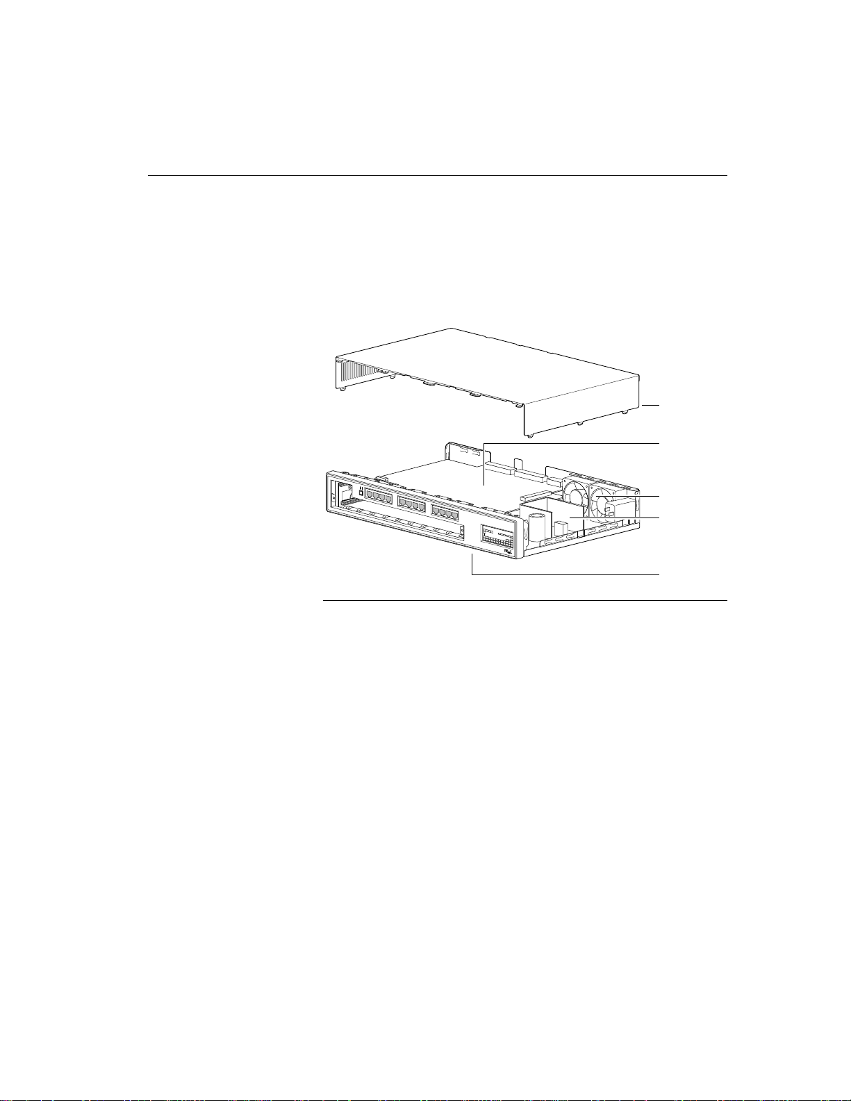
Chassis
The Express hub components are enclosed in a 19-inch (48.26centimeter) wide chassis, which is 1.5 EIA rack-mount spaces high.
The chassis consists of a metal frame and a plastic front panel, and it
contains components that are pertinent to the operation of the hub.
Cover
Motherboard
Fans
Intel
100BASE-TX Stackable Hub
Express
Technology by
Bay Networks
Power
supply
Front panel
5905
Express 100BASE-TX stackable hub
Major Components
The chassis contains the following major components:
• Motherboard
• AC power supply
• Two fans
The motherboard in the Express hub contains the circuitry that drives
and processes all 100BASE-T repeater functions.
The Express hub is equipped with a 120/240 V AC universal power
supply. All components and plug-in modules derive their power from
the AC power supply.
The hub is equipped with two fans that cool the hub components and
ensure normal operation.
3
Page 12
C H A P T E R 1 Intel Express 100BASE-TX Stackable Hub
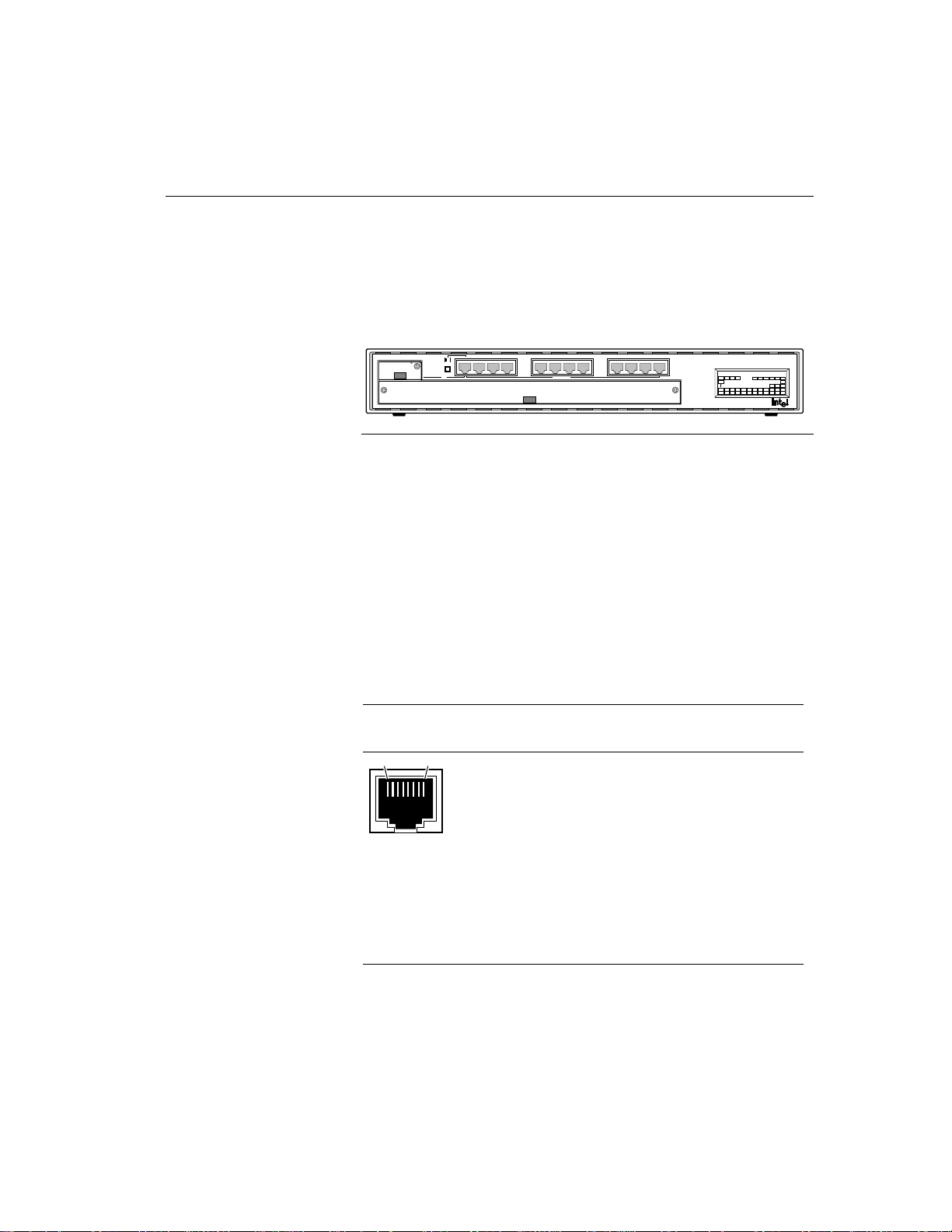
Front Panel
The front panel of the Express hub provides 12 100BASE-T ports, an
MDI/MDI-X switch, an LED matrix, a media adapter slot, and an
expansion slot.
Media Adapter
Front panel of the Express 100BASE-TX stackable hub
RJ-45 100BASE-TX Ports
The front panel of the Express hub provides 12 100BASE-TX ports
with fixed RJ-45 connectors for connectivity to 100BASE-T network
devices. These standard RJ-45 connectors accept Category 5
unshielded twisted pair (UTP) or 100-ohm shielded twisted pair (STP)
cable. The RJ-45 interface consists of an 8-pin connector configured
for MDI-X wiring.
24365871091211
MDI-X/MDI
1
100 BASE-TX
Expansion Slot
Technology by
Bay Networks
Intel Express
100BASE-TX Stackable Hub
²1 5 10 15 25 ³30
Pwr Stat RPS Col Data %
Media Adapter
Expansion Slot
1
Port Status
Management
1132143154165176187198209211022112312
Stat Enbl
Stat
Mstr
24
5895
This table provides the pinout information for the standard RJ-45
connector configured for MDI-X wiring, and the pinout information
for port 1 RJ-45 connector when configured for MDI wiring.
Pin # MDI-X signal MDI signal
(port 1)
18
3165.1
4
1
2
3
4
5
6
7
8
Receive data + (RD+)
Receive data - (RD-)
Transmit data + (TD+)
Not assigned
Not assigned
Transmit data - (TD-)
Not assigned
Not assigned
TD+
TDRD+
Not assigned
Not assigned
RDNot assigned
Not assigned
Page 13

CHAPTER 1 Overview
The maximum cable distance between the port and the attached device
is 100 meters (328 feet), including all patch cables, panels, and
connectors.
MDI/MDI-X Switch
The MDI/MDI-X switch on the front panel of the Express hub is a
recessed push-button switch that allows you to select MDI or MDI-X
wiring for port 1. As indicated on the front panel, port 1 is configured
for MDI-X wiring when the push button is in the out position. When
the push button is pressed in, port 1 is configured for MDI wiring.
The MDI/MDI-X switch eliminates the need to use a crossover cable
if you are connecting similar devices. Use the following guidelines to
configure port 1 for MDI or MDI-X wiring:
• Configure port 1 for MDI-X wiring if the remote end of the cable
is connecting to an MDI-wired device (such as a network station
or a router).
• Configure port 1 for MDI wiring if the remote end of the cable is
connecting to an MDI-X device, such as a 10/100 Mbps switch.
MDI-X ports 2 through 12 cannot be configured for MDI wiring. If
you are using one of these ports to connect to another MDI-X port,
you must use an RJ-45 crossover cable to connect the two ports.
LED Matrix
The LED matrix on the front panel of the Express hub allows you to
identify:
• The status of the hub AC power supply.
• The operational status of the hub.
• A collision occurrence on an Ethernet segment in a standalone hub
or a stack of hubs.
• The network utilization of the Ethernet segment in a standalone
hub or a stack of hubs.
• The status of the expansion module or the status and mode of a
network management module (NMM) installed in the expansion
slot.
• The status for all ports in the hub, including port 1 on the optional
media adapter when installed in the media adapter slot.
5
Page 14

C H A P T E R 1 Intel Express 100BASE-TX Stackable Hub
This shows the LED matrix on the Express hub.
100BASE-T Hub
Pwr Stat RPS Col Data %
1
Media Adapter
Port Status
1132143154165176187198209211022112312
1 5 10 20 35 50
Management
Expansion Slot
Stat Enbl
Mstr
LED matrix on the Express hub
Type Label Color Meaning
Stat
24
5897
Hub power supply status Pwr Green
Off
Hub status Stat Green
Hub is receiving AC power.
Hub is not receiving AC power.
Hub is powered, has passed the confidence test, and
is operating normally.
Amber
At initial power up, this LED lights to indicate the
hub is running its confidence test. If this LED lights
after the confidence test is performed, it indicates the
hub is not operating normally due to a fan failure, a
hub power supply failure, or a confidence test failure.
Off
Hub is not receiving power.
Not used RPS N/A N/A
Collision
Col Amber
A collision event has been detected.
status
Off
Network utilization Data % Blinking
green
Collisions are not detected on the segment.
The ≤1% LED blinks green to indicate there is traffic
on the segment that is utilizing less than 1% of the
network.
Solid green
The Data % LEDs light solid green to indicate the
percentage of the network utilization for the Ethernet
segment in a standalone hub or a stack of hubs. These
LEDs operate as a bar graph to provide you with a
continuous indication of the network utilization. For
example, if the 1% and 5% Data LED light green, the
Ethernet segment in that stack of hubs is utilizing 5%
of the network.
6
Page 15

CHAPTER 1 Overview
Type Label Color Meaning
100BASE-T Media
adapter status
Expansion slot module
status
Management status Stat
Port status
(hub ports)
Port status
(optional ports)
Media
Adapter 1
Expansion
Slot Stat
Mstr
Enbl
Port
Status
1—12
13—24
Green
Amber
Off
Green
Amber
Off
Green
Amber
Green
Off
Green
Off
Green
Amber
Off
A media adapter is installed in the media adapter slot,
link status is good, and the port is not partitioned.
Link status is good and the port is partitioned.
Link status is not detected or a media adapter is not
installed in the media adapter slot.
The module in the expansion slot has passed the
confidence test and is operating normally.
The module in the expansion slot has failed.
There is no module installed in the expansion slot.
The NMM has passed the confidence test and is
operating normally.
The NMM has failed.
The NMM installed in the hub is the master NMM
for a stack of hubs.
The NMM installed in the hub is not the master
NMM for that stack of hubs.
The hub is properly connected to the other hubs in
the stack and is actively managed by an NMM.
The hub is not managed by an NMM.
Link status is good; port is not partitioned.
Link status is good; port is partitioned.
Link status is not detected; port may or may not be
partitioned.
7
Page 16
C H A P T E R 1 Intel Express 100BASE-TX Stackable Hub
e
E
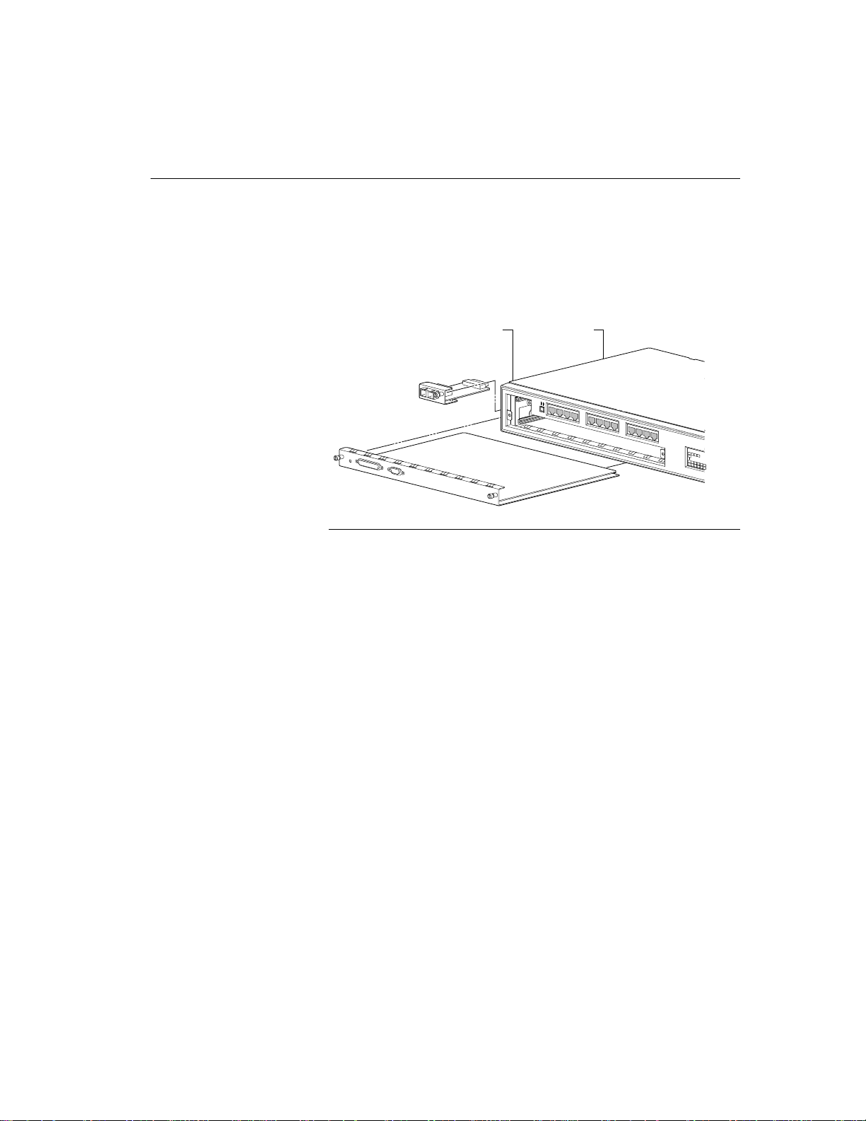
100BASE-T Media Adapter Slot
The media adapter slot is located in the upper left-hand corner of the
Express hub and accommodates an optional 100BASE-T media
adapter. A 100BASE-T media adapter allows you to connect to other
100BASE-T network devices using a different media.
Media adapter slot Expansion slot
Media adapter and expansion slots in the Express hub
For more information about the optional media adapter, see “Media
Adapters” later in this chapter.
Technology by
Bay Networks
5906
Int
100BAS
Expansion Slot
The expansion slot is located in the lower half of the Express hub and
accommodates several optional 100BASE-T modules that extend your
networking capabilities.
The following 100BASE-T modules can be installed in the expansion
slot:
• 100BASE-T NMM
• 100BASE-TX host module
For information about these modules, see “Optional Equipment” in
Appendix A.
8
Page 17
CHAPTER 1 Overview
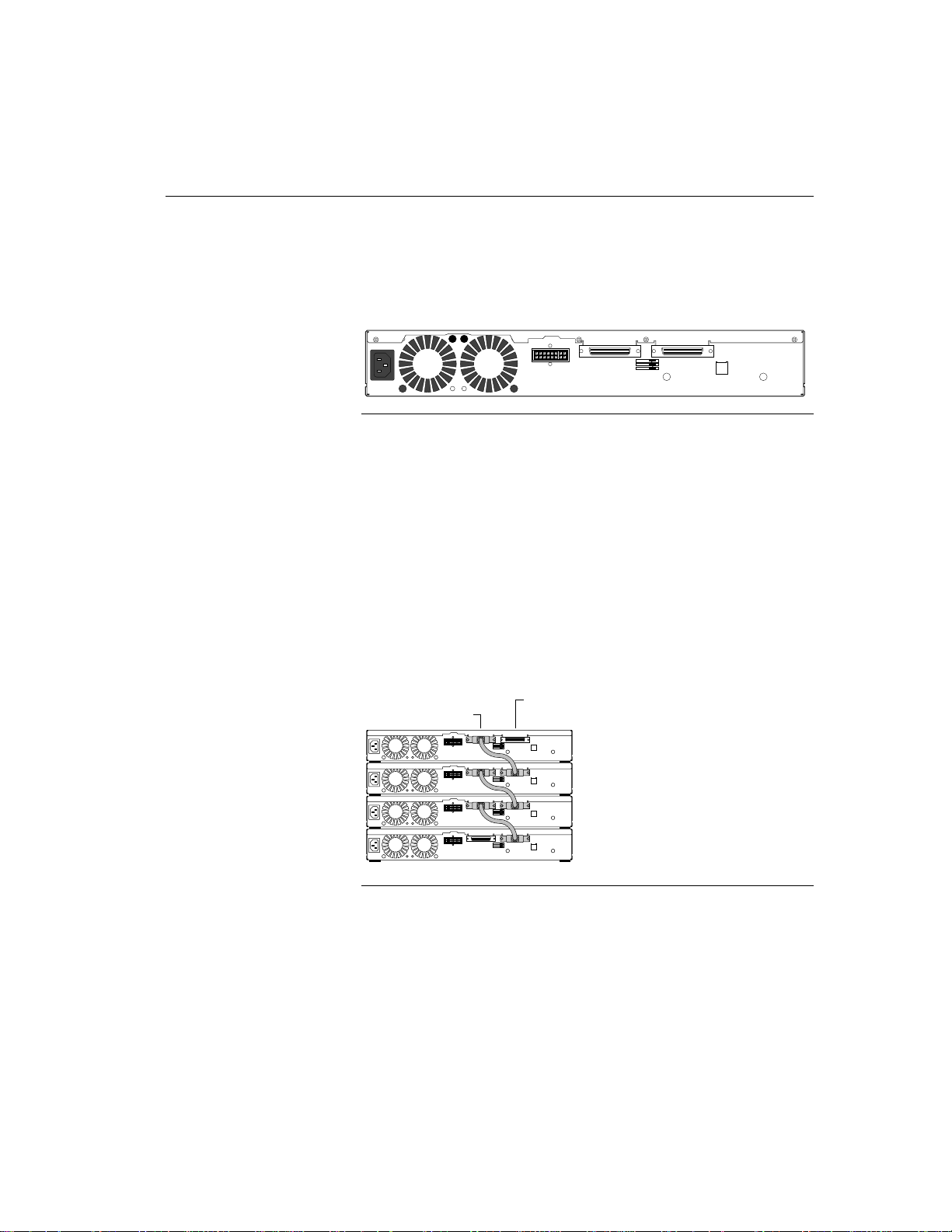
Rear Panel
The rear panel of the Express hub provides an AC power receptacle, a
Redundant Power connector, and two cascade cable connectors.
100-240V
5.0-3.0A
47-63HZ
Redundant Power
Cascade Down Cascade Up
Unit Position
1
2
3
5898
Rear panel of the Express hub
Power Receptacle
The AC power receptacle is provided for connection to the AC power
outlet. The Express hub accepts between 100 and 240 V AC.
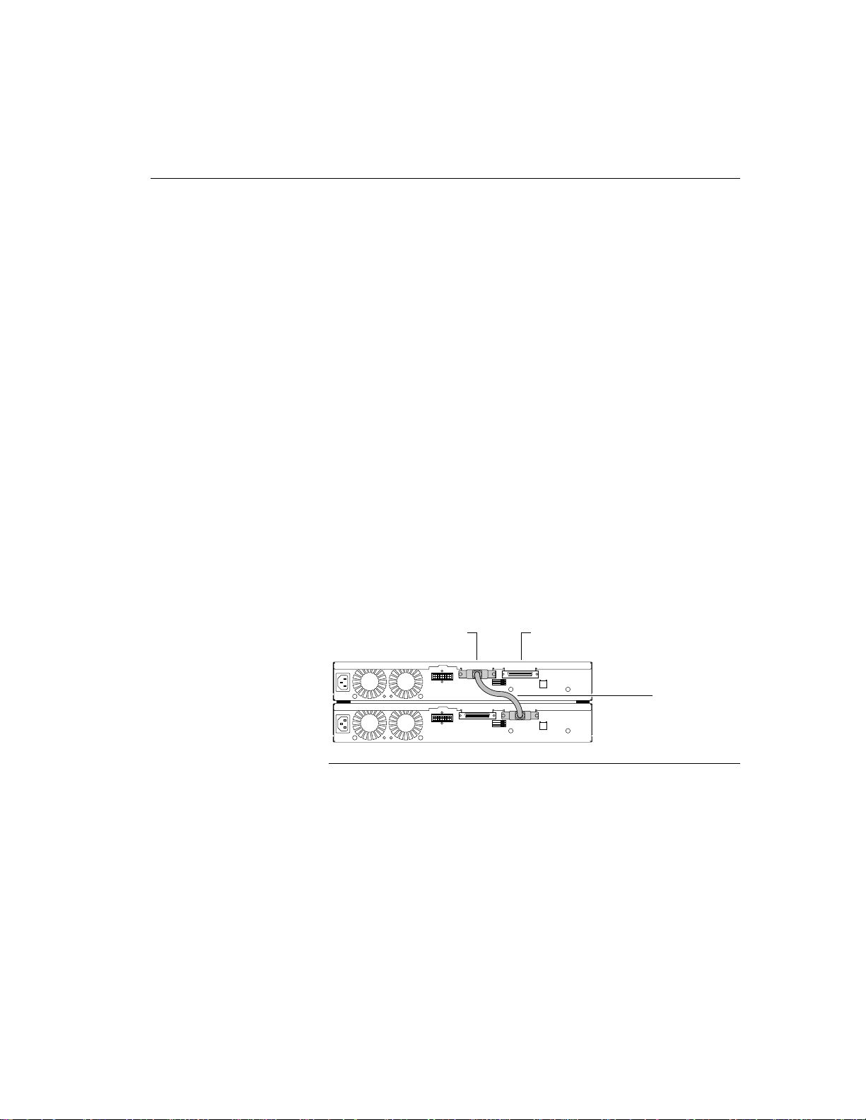
Cascade Connectors
The Cascade Down and Cascade Up connectors and an Intel cascade
cable allow you to stack and link multiple Express hubs so you can
expand port connections at a particular workgroup in your network.
The cascade cable connects to the Cascade Down cable on the top hub
and the Cascade Up cable on the bottom hub.
Cascade
down
Cascade
up
Cascade cable connections
5903
9
Page 18

C H A P T E R 1 Intel Express 100BASE-TX Stackable Hub
The cascade cable extends the functionality of one hub to a maximum
of six hubs in a stack. This stack then functions as a single repeater or
collision domain. The cascade cable daisy chain creates a cascade bus
that carries the following information to each hub in the stack:
• Multidrop repeater Ethernet segment information—allows you to
have a total of 72 fixed ports on one segment. When the optional
100BASE-T host module is installed in the expansion slot on each
hub, the Ethernet segment supports up to 144 ports.
• Stack management information—allows one NMM to manage
every hub in the stack.
• Port statistics—distributes configuration and status information
for each port in the stack to an NMM and network management
system.
• Daisy chain unit number information—provides a sequential
numbering convention for a stack of up to six hubs. For
information about the unit numbering convention, see “Unit
Numbering Convention” in Chapter 3, “Physical Configuration
Guidelines.”
10
Page 19

NOTE
Only qualified technicians
should install and maintain
this equipment.
Installing and
Removing the
Express Hub
This chapter describes
• Preparing the installation site.
• Unpacking the equipment.
• Meeting tool and materials requirements.
• Installing the hub.
• Installing multiple hubs.
• Removing a hub.
• Installing and removing filler panels.
11
Page 20

C H A P T E R 2 Intel Express 100BASE-TX Stackable Hub
Site Preparation
Before you install the Express hub, prepare the installation site. Make
sure the operating environment meets the physical requirements of the
equipment.
Operating
environment
Temperature Ambient temperature between 5° C and 40° C
Humidity Between 5% and 85% noncondensing
Ventilation Minimum 2 in (5.08 cm) on all sides for cooling
Operating
conditions
Service access Minimum 12 in (19.68 cm) front and rear for
Power Adequate power source within 6 ft (1.83 m)
Table and shelf
installation
requirements
Rack installation
requirements
Wiring hardware Wiring hardware, such as punchdown blocks or
Requirement
(41° F and 104° F)
No nearby heat sources such as direct sunlight,
warm air exhausts, or heaters
Adequate airflow in room or wiring closet
At least 6 ft (1.83 m) to nearest source of
electromagnetic noise (such as photocopy
machine or arc welder)
service access and maintenance
Front and rear clearance for cables and wiring
hardware such as punchdown blocks
Approximately 13.25-in. (33.66 cm) by 19.25-in.
(48.90 cm) area on a level tabletop or shelf
Support for at least 10 lbs (4.5 kg) per Express
hub with filler panels installed in expansion and
media adapter slots
Support for at least 12.3 lbs (5.6 kg) per Express
hub with an optional NMM installed the
expansion slot and an optional media adapter
module installed in the media adapter slot
Standard 19-in (48.26 cm) EIA equipment rack
1.5 EIA rack-mount spaces available for each
Express hub
patch panels, in place before installing the hub
12
Page 21

C H A P T E R 2 Installing and Removing the Express Hub
Package Contents
Before you install the Express hub, check to see that you have these
items:
Power cord
100BASE-T hub
Intel
100BASE-TX Stackable Hub
Express
Technology by
Bay Networks
Screws
&
Feet
10 bracket screws,
4 rack screws
with nylon washers
2 mounting
brackets User guide
5907.1
Package contents
If any items are missing or damaged, contact the sales or customer
service representative from whom you purchased your equipment.
Required Tools and Materials
To install the Express hub, you need the following tools and materials:
• Cascade cable (Intel order number EC100CC) for connecting two
stacked hubs (a full stack of six hubs requires five cascade cables).
• #1 Phillips screwdriver for attaching mounting brackets
• #2 Phillips screwdriver for tightening mounting screws
• Antistatic mat and wrist strap (attached to an antistatic leash) to
protect electronic components from static electricity damage
13
Page 22

C H A P T E R 2 Intel Express 100BASE-TX Stackable Hub
Installing an Express hub
This section provides information and instructions for installing a
single Express hub in a rack or on a table or shelf. For instructions on
installing multiple Express hubs, see “Installing Multiple Hubs” later
in this chapter.
Installing the Hub in a Rack
To install the hub in a rack, follow these steps:
1. Attach the mounting brackets to the sides of the hub.
a. Hold a mounting bracket against each side of the hub, as shown
in the illustration below, and align the countersunk screw holes
in the bracket with the bracket mounting holes in the hub.
b. Insert the screws provided with the mounting brackets through
each bracket and into the bracket mounting holes in the hub.
c. Using a #1 Phillips screwdriver, tighten the screws to secure
each bracket.
2. Hold the hub with the mounting holes in the brackets aligned with
holes in the rack.
14
Installing the hub in an equipment rack
Intel
100BASE-TX Stackable Hub
Express
Technology by
Bay Networks
5908
Page 23

C H A P T E R 2 Installing and Removing the Express Hub
3. Insert two pan-head screws with nylon washers through each
mounting bracket and into the rack.
4. Using a #2 Phillips screwdriver, tighten the screws to secure the
hub to the rack.
5. Continue with “Completing the Installation” to finish this
installation procedure.
Installing the Hub on a Table or Shelf
To install the hub on a table or shelf, follow these steps:
1. Install self-adhesive feet on the bottom of the hub.
Peel off the protective backing from the rubber feet and apply one
at each marked location on the bottom of the hub.
Feet placement
guides
CAUTION
Do not connect the power
cords to the hubs until all the
units in the stack are installed
and hubs are connected by
cascade cables and are ready
for operation.
4642
Attaching feet
2. Set the hub on a table or shelf so that it has at least 2 inches of
space on all sides.
3. Continue with “Completing the Installation” to finish this
installation procedure.
Completing the Installation
After you have installed the Express hub, connect power to the hub
and verify the installation.
To complete the installation of your Express hub, follow these steps:
1. Install any additional units in your stack (such as Express hubs).
For instructions on installing multiple hubs, see “Installing
Multiple Hubs” later in this chapter.
15
Page 24

C H A P T E R 2 Intel Express 100BASE-TX Stackable Hub
2. Install any optional modules in the media adapter and/or
expansion slots in the hub.
a. Remove the filler panel from the slot.
For instructions on removing filler panels, see “Installing and
Removing Filler Panels” later in this chapter.
b. Install the module in the appropriate slot.
The media adapter fits into the media adapter slot. For
instructions on installing a media adapter, refer to the
documentation that shipped with your media adapter.
The NMM fits into the expansion slot. For instructions on
installing an NMM, refer to the documentation that shipped
with your NMM.
The 100BASE-TX Host Module fits into the expansion slot.
For instructions on installing a 100BASE-TX Host Module,
refer to the documentation that shipped with your host module.
3. Make the connections to the ports on the hub and optional
installed media adapter and host module.
For instructions on making connections to ports, see “Making
Connections to 100BASE-T Ports” in Chapter 3.
4. When installation for each unit in your stack is complete, connect
the power cord(s) to the hub.
Connect the power cord(s), first to the power entry receptacle on
the hub rear panel and then to the wall.
CAUTION
The power cord is a North
American type, UL-listed/
CSA-certified power supply
cord. Immediately discard
this cord if it is inappropriate
for the electrical system of
your country, and obtain the
proper cord as required by
your national electrical codes
or ordinances.
5. Verify the installation.
For instructions on verifying the installation, see “Verifying
Installa tion” in Chapter 3.
16
Page 25

C H A P T E R 2 Installing and Removing the Express Hub
Installing Multiple Hubs
This section describes building a stack of Express hubs. Included in
this section are the guidelines for stacking and cascading Express hubs
and the physical requirements for installing multiple hubs. Review the
guidelines and requirements before installing your equipment.
Stacking and Cascading Hubs
You can connect multiple hubs together to increase the number of
connections to your network. A stack of a maximum of six hubs can
be installed in the standard 19-in (48.26-cm) equipment rack or on a
shelf or a table. Once the hubs are stacked and secured either in the
rack or on a table or shelf, you can connect them in the stack using
Intel cascade cables.
The cascade cable is a unique cable for the Express hub. Use this cable
to connect two adjacent hubs in a stack. You can connect two adjacent
hubs as long as the distance between the two hubs is not greater than 2
inches (0.05 meters).
Physical Requirements for Installing
Multiple Hubs
When you install a stack of Express hubs, consider the following
installation requirements:
• The mounting requirements for installing multiple hubs
• The requirements for installing NMMs
17
Page 26

C H A P T E R 2 Intel Express 100BASE-TX Stackable Hub
Mounting Requirements for Installing Multiple
Hubs
Position the hub you want to be numbered 1 at the top of the stack.
When an NMM is installed in the stack, it assigns unit numbers
starting from the top of the stack. For information about the unit
numbering convention, see “Unit Numbering Convention” in
Chapter 3.
For rack installations, you should leave enough room in the rack to
expand the stack to six hubs. Each hub occupies 1.5 EIA rack-mount
spaces. For table or shelf installations, make sure the shelf or table can
support the weight of six fully equipped hubs. See “Site Preparation,”
earlier in this chapter, for a list of table and shelf installation
requirements.
Installing Optional Modules in the Hub
You can install an optional 100BASE-T media adapter in the media
adapter slot and an optional 100BASE-T host module or 100BASE-T
NMM in the expansion slot. You should install the modules in the hub
before connecting power to the hub. If the modules are installed in
these slots when the hub is powered, the hub may reset when the
module is inserted into the slot. During a reset, you will temporarily
lose port connectivity in the hub that is reset. In nonredundant
management configurations, if you reset a hub equipped with an
NMM, you will temporarily lose management to the entire stack of
hubs.
18
Installing Network Management Modules
Any Express hub in a stack can accommodate the 100BASE-T NMM,
however, it is recommended that you install the NMM in the hub at
the top of your stack. When an NMM is installed in the stack, it
automatically assigns and stores the numbers of the hubs in the stack.
In a redundant management configuration, you can install two
100BASE-T NMMs in two separate hubs in the stack. One of the
NMMs is designated the master NMM and actively manages the stack,
while the second NMM operates in a standby mode. For more
information about the NMM and redundant management
configuration, refer to the documentation that shipped with your
NMM.
Page 27
C H A P T E R 2 Installing and Removing the Express Hub
Installing and Connecting Multiple
Hubs
The procedure for installing and connecting multiple hubs is similar
for rack installations and table or shelf installations. When installing
multiple hubs, follow this sequence:
• Install the hubs.
• Connect the hubs together using the cascade cables.
• Connect the power cords to the hubs.
To install multiple hubs, follow these steps:
1. Install one hub at a time in the rack or on the shelf or table.
Refer to “Installing the Hub in a Rack” or “Installing the Hub on a
Table or Shelf” earlier in this chapter.
CAUTION
Do not connect the power
cord to the hub until all the
hubs are installed, connected
together through the cascade
cable, and ready for
operation.
2. Connect the hubs using the cascade cables.
To install the cascade cable:
a. Ensure the power cords are not connected to the hubs you are
connecting.
The Pwr LED on the front panels of the hubs should be off.
b. Connect one end of the cascade cable to the Cascade Down
connector on the rear panel of the hub on the top.
Cascade down Cascade up
Cascade cable
Installing a cascade cable
c. Connect the other end of the cascade cable to the Cascade Up
connector on the rear panel of the hub on the bottom.
5912
19
Page 28

C H A P T E R 2 Intel Express 100BASE-TX Stackable Hub
d. Tighten the screw locks on the cable connectors to secure the
plug to the hub.
CAUTION
Check that the screw locks on
the cable connectors are fully
tightened and the cable
connection is secure. A faulty
cable connection could
disrupt the operation of the
entire stack.
e. Repeat steps a through d for all the hubs in the stack.
3. Connect the power cords to the AC power receptacles on the rear
panel of all the hubs in the stack.
Connect the power cord to the AC power receptacles on the hub
and then to the power outlet.
Removing an Express hub
This section provides instructions for removing an Express hub from a
stack. When removing an Express hub from a stack, follow this
sequence:
NOTE
You may need an assistant to
remove a hub from a stack
that is located on a table or a
shelf.
CAUTION
Removing a hub removes
port connectivity for that hub
from the network. When you
remove a hub from the
middle of the stack (a hub
that is in the middle of the
stack is any hub that is
located between two
operating hubs), you split the
Ethernet segment into two
separate segments.
1. Disconnect power cords from the AC power receptacle on the hub
rear panel.
All power sources should be disconnected. To verify that power
sources are disconnected, check that the Pwr LED on the hub front
panel is off.
2. Disconnect the cascade cables from the Cascade Down and
Cascade Up connectors on the hub rear panel.
Save the cascade cable that was removed with the inoperable hub
for later use.
3. Connect the free end of the cable connected to the Cascade Down
connector on the hub above the inoperable hub to the Cascade Up
connector on the hub below the inoperable hub.
Cascade down Cascade up
Installing a cascade cable
Cascade cable
5912
20
Page 29

C H A P T E R 2 Installing and Removing the Express Hub
For hubs that are mounted on a rack, you may have to remove the
inoperable hub from the stack and move the adjacent hub up one
rack mounting space, or install a replacement hub in the rack,
before connecting the cascade cable to the new hub.
For hubs that are mounted on a table or shelf, remove the
inoperable hub before connecting the cascade cable to the new
hub.
CAUTION
Check that the screw locks on
the cable connectors are fully
tightened and the cable
connection is secure. A faulty
cable connection could
disrupt the operation of the
entire stack.
4. To remove the hub from the rack, follow these steps:
a. Use a #2 Phillips screwdriver, loosen the screws that secure
each mounting bracket to the rack.
b. Remove the screws from the mounting bracket while
supporting the bottom of the hub, then carefully remove the
hub from the rack.
5. To remove the hub from a stack that is mounted on a table or
shelf, gently lift the hub or hubs that are stacked on top of the hub
to be replaced, and carefully remove that hub from the stack.
Removing and Installing Filler
Panels
The Express hub is shipped with filler panels installed in the media
adapter and expansion slots. The filler panels serve the following
functions:
• Provide a safety barrier against reaching into an operating hub
• Maintain proper airflow for cooling the hub
The filler panels can easily be removed when you are ready to install
modules in the media adapter and expansion slots. Remember to keep
your filler panels for future use; you should reinstall the filler panel if
you have to remove a module from a slot for an extended length of
time. This section describes how to remove and install filler panels.
21
Page 30

C H A P T E R 2 Intel Express 100BASE-TX Stackable Hub
T
To remove a filler panel, loosen the screws on the front of the filler
panel, grasp the tab on the front of the panel, and pull the filler panel
out of the slot.
Removing a filler panel
To install a filler panel, follow these steps:
1. Align the left and right edges of the filler panel in the card guides
at the left and right of the slot.
2. Slide the filler panel in until the front panel of the filler panel is
flush with the front panel of the hub.
3. Tighten the screws to secure the filler panel to the hub.
Technology by
Bay Networks
5914
Intel
100BASE
22
Installing filler panels
Technology by
Bay Networks
Inte
100BASE-
Page 31

Physical
Configuration
Guidelines
This chapter describes
• Making connections to ports on the Express hub.
• Verifying the installation.
• The unit numbering convention.
• Typical 100BASE-T network configurations.
Making Connections to
100BASE-T Ports
This section provides the information you need to know before you
connect cables to the 100BASE-T ports on the hub and the optional
100BASE-T Media Adapters and 100BASE-T Host Modules. This
information covers the following topics:
• Making decisions about your network configuration
• Ensuring your network devices are configured for 100 Mbps
operation
This section also provides information about making cable
connections to 100BASE-T ports on the Express hub.
23
Page 32

C H A P T E R 3 Intel Express 100BASE-TX Stackable Hub
Network Configuration Decisions
Before connecting your network devices to the ports on the Express
hub, make sure you have made the following network configuration
decisions:
• Ensure that the new connections are within the simple Fast
Ethernet repeater rules.
• Ensure that all 100BASE-T connections are within their cable
length limits.
• Determine what kinds of cables you will use for 100BASE-T port
connections. Ensure that the cables you choose comply with the
type of port you are connecting to.
• Determine which 100BASE-T modules you will need to install in
the hub (if any) for connecting your network devices.
Refer to Appendix B to review the guidelines that can help you
determine your network configuration.
100 Mbps Network Devices
24
To connect 100BASE-T network devices (such as, workstations,
servers, and printers) to the 100BASE-T Hub, you must ensure that
each device is physically and logically configured to operate at 100
Mbps Fast Ethernet.
Your 100BASE-T network devices should include 10/100 Mbps
adapter cards or 100 Mbps adapter cards that allow the device to
transmit and receive data over 100 Mbps pipes. To enable the 100
Mbps “pipes” to be used efficiently, you may have to modify the
device configuration files.
If the network devices have not been configured for 100 Mbps Fast
Ethernet operation, make sure you plan an adequate amount of time to
rearchitect your network.
For instructions on installing adapter cards and configuring network
devices, refer to the documentation that shipped with your adapter
card. If these instructions do not include instructions regarding the
reconfiguring of your device, check the documentation that shipped
with that device for this information.
Page 33
C H A P T E R 3 Physical Configuration Guidelines
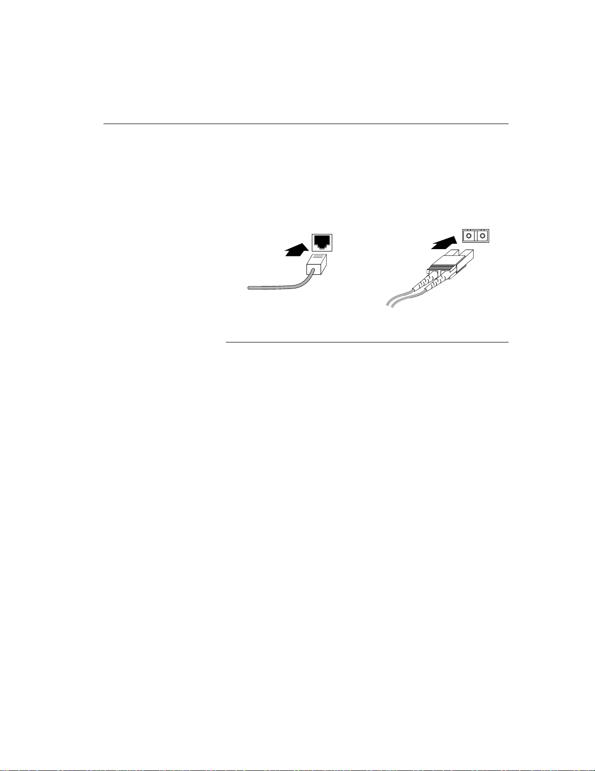
Connecting Cables to the Hub
You can connect devices directly to ports on the Express hub, or to
ports on installed media adapter and host modules. This illustration
shows how to connect UTP or STP cable to RJ-45 connectors and fiber
optic cable to SC connectors.
UTP or STP cable connection to RJ-45 port Fiber optic cable connection to SC port
Connecting cables to the hub
The 100BASE-T ports on the Express hub and optional 100BASE-T
modules can be connected to the following network devices that are
operating at 100 Mbps Fast Ethernet:
• Workstations
• Servers
• Printers
• Transceivers
• Switching hubs
• Routers
5919.1
See “100BASE-T Network Configurations” later in this chapter for
information about making cable connections to 100 Mbps switching
hubs. For information about making connections to other 100BASE-T
devices, refer to the documentation that shipped with the device.
25
Page 34

C H A P T E R 3 Intel Express 100BASE-TX Stackable Hub
Verifying Installation
After you complete all port and power connections to the Express hub,
verify that the installation is successful by observing the LEDs on the
front panel of the hub.
This section provides information about the operating conditions of
the LEDs after power is first applied to a newly installed Express hub.
100BASE-T Hub
Pwr Stat RPS Col Data %
1
Media Adapter
Port Status
1132143154165176187198209211022112312
LED matrix on the Express hub
Checking the LEDs
1 5 10 20 35 50
Management
Expansion Slot
Stat Enbl
Mstr
Stat
24
5897
26
When power is first applied to the Express hub, a confidence test is
performed. During the confidence test, the hub Stat LED lights amber
to indicate the confidence test is in progress.
When the confidence test is successfully completed, the LEDs on the
hub front panel should appear as follows:
• The Pwr LED lights green to indicate the hub is receiving power
from the hub AC power supply.
• The Stat LED lights green to indicate the hub has passed the
confidence test and is operating normally.
• The Data % LEDs light green on each individual hub to indicate
the overall network utilization percentage of the Ethernet segment
for a standalone hub or a stack of hubs.
• If an optional media adapter module is installed in the media
adapter slot, the appropriate cable is connected to the media
adapter port, and the link status is good, the Media Adapter 1 LED
lights green.
Page 35

C H A P T E R 3 Physical Configuration Guidelines
• If an optional module is installed in the expansion slot, the
Expansion Slot Stat LED lights green to indicate the module in the
expansion slot has passed the confidence test and is operating
normally.
• If an optional NMM is installed in the expansion slot, the
Management LEDs light as follows:
– The Stat LED lights green to indicate the NMM has passed the
confidence test and is operating normally.
– The Mstr LED lights green to indicate the NMM is the master
NMM in the stack.
• The Enbl LEDs on each hub in the stack lights green to indicate
that the hub is properly connected to the other hubs in the stack
and is actively managed by an NMM located in one of the hubs in
the stack.
• A Port Status LED for each port on the hub (1-12) and each port
on an optional installed host module (13-24) provides port status.
LED Color Status indications
Hub ports 1–12
and 100BASE-T
host module ports 13-24
Green Link is good, port is not
partitioned.
Amber Link is good, port is partitioned.
Off Link is not detected, port is either
partitioned or not.
Other Items To Check
You can check the following additional items:
• Verify that each connected station operates properly.
• If an NMM is installed:
– Verify that the NMM is installed properly (refer to the
documentation that shipped with your NMM).
– Refer to the documentation that shipped with your 100BASE-T
NMM to verify the operation of the hub through its service
port.
27
Page 36

C H A P T E R 3 Intel Express 100BASE-TX Stackable Hub
Unit Numbering Convention
This section provides information about the hub unit numbering
convention. The unit numbering convention is invoked when an NMM
is installed in one of the Express hubs in a stack.
When Express hubs are stacked, cascaded, and powered, they are
assigned “unit” numbers that are stored in nonvolatile memory on the
hub motherboard. The NMM assigns units numbers from the top
down—the hub at the top of the stack is assigned unit 1, the hub below
unit 1 is assigned unit 2, and so on. Unit numbers are assigned
according to the physical location of the hub in the stack.
In a fully equipped stack, hubs are assigned unit numbers 1 through 6.
You can identify the unit numbers of the hubs in the stack through
your network management software.
As you build your stack to include more hubs, each hub that is added
to the stack is assigned a unit number that relates to the position of the
unit in the stack. For example, if you have four hubs in your stack
and you add a hub to the bottom of the stack, the new unit is assigned
unit 5. If you install your new hub at the top of the stack, the new hub
is assigned unit 1 and the hubs below the new hub are reset and
renumbered in sequence.
28
Page 37

C H A P T E R 3 Physical Configuration Guidelines
In a stack of four hubs, if you remove a hub that is assigned unit 2 and
connect the cascade cable of unit 1 to unit 3, the hub that was assigned
unit 3 will reset and be renumbered as unit 2.
CAUTION
Removing a hub removes
port connectivity for that hub
from the network. In
nonredundant management
configurations, removing a
hub equipped with an NMM
removes management from
the entire stack. When you
remove a hub from the
middle of the stack (a hub
that is in the middle of the
stack is any hub that is
located between two
operating hubs), you split the
Ethernet segment into two
separate segments when the
cascade cable is disconnected
from the top and bottom
hubs.
100BASE-T Network
Configurations
This section provides information about the typical 100BASE-T
network configurations that incorporate the Express hub. The versatile
repeater plays a key role in a 100BASE-T shared local area network
(LAN) and a 100BASE-T switched LAN. In both high-speed network
configurations, the repeater is installed in the wiring closet to greatly
increase the performance of your network.
100BASE-T Shared LAN
Users who are operating network intensive applications on powerful
workstations require more bandwidth than the conventional 10BASET network can offer, therefore requiring the need for expanded
bandwidth. By migrating users who require more bandwidth to devices
that operate at 100 Mbps Fast Ethernet, you can greatly increase their
bandwidth and response times. By installing the Express hub in your
network, you can create a power workgroup with many users who can
share access to centralized network devices, such as servers and
printers, that are operating at 100 Mbps.
29
Page 38

C H A P T E R 3 Intel Express 100BASE-TX Stackable Hub
Connecting 100BASE-T Workstations to the Hub
You can connect up to 12 workstations to 12 fixed ports with RJ-45
connectors on the Express hub, provided that the workstations are
configured to operate at 100 Mbps (see “100 Mbps Network Devices”
earlier in this chapter). This illustration shows a UTP cable that is
connected to an RJ-45 connector on a 100 Mbps adapter card installed
in a workstation. The other end of the 100 meter maximum UTP cable
is connected to one of the RJ-45 connectors on the hub (see
“Connecting Cables to the Hub” earlier in this chapter).
Network
adapter with
RJ-45 jack
UTP cable
with RJ-45 plug
30
2013.6
Connecting 100BASE-T workstations to the hub
The flexible and scaleable architecture of the Express hub allows you
to stack up to six hubs for connection to 72 network devices that share
one Fast Ethernet segment. In addition, an optional media adapter
module can be installed in the hub to provide you with an alternate
type of port connectivity for port 1.
If you install optional 100BASE-T host modules in each expansion
slot in a fully equipped stack, you can connect up to 132 network
devices to the shared Fast Ethernet segment. As you connect more
nodes to the stack, you may want to integrate a 100 Mbps switching
hub into your shared LAN. Each 100BASE-T workgroup can be
connected to an individual port on the 100 Mbps switching hub to
provide 100 Mbps dedicated bandwidth to the workgroup.
Page 39

C H A P T E R 3 Physical Configuration Guidelines
100BASE-T Switched LAN
Integrating switching into the network enables network
microsegmentation, which increases the total capacity and
performance of the network. You can add 100 Mbps workgroups to the
network and connect them to individual ports on the switch. For those
networks that still support 10BASE-T workstations, an Ethernet
switching hub provides configurable ports for 10 Mbps or 100 Mbps
connections. When a port is configured to operate at 10 Mbps, the
workstations running applications across 10 Mbps links can access
centralized servers through the switching hub.
Here is how the 100BASE-T Hub in the wiring closet interfaces with a
switching hub in the mid-tier network center to increase the total
capacity and performance of an entire network.
Mid-tier network center
System 5000 hub
•
•
•
100 Mb/s
fiber link (port 1)
Stack of
100BASE-T hubs
100 m
•
•
•
100BASE-T
•
•
engineering
•
workgroup
1 m
transceiver
100BASE-TX
switching hub
Servers
with 100 Mb/s
adapters
10BASE-T
workstations
Router
Stack of
100BASE-T hubs
•
•
•
•
100BASE-T
administrative
workgroup
Legend
10 Mb/s UTP
100 Mb/s UTP
100 Mb/s fiber
5877.1
100BASE-T switched LAN
As you can see, two groups of 100 Mbps workstations are connected to
two separate repeaters in the wiring closet. The 100BASE-T Hubs can
be stacked to provide multiple ports per repeater. This network shows
two repeater stacks that support individual workgroups.
A 100BASE-FX media adapter is installed in the 100BASE-T Hub and
allows you to connect a repeater or repeater stack to the switching hub
through a 100 Mbps fiber link. Two servers equipped with 100 Mbps
adapter cards and a router equipped with a 100BASE-T interface are
also located in the network center to provide centralized services to
workstations that are operating at 100 Mbps and 10 Mbps. Users with
10 Mbps workstations are connected to a System 5000 hub that is also
located in the mid-tier network center.
31
Page 40

C H A P T E R 3 Intel Express 100BASE-TX Stackable Hub
By integrating the switching hub into the network that populates both
10 Mbps and 100 Mbps workstations, both groups experience the
benefits of high-speed networking, even if they are not operating at
the faster data transmission speed—both groups receive dedicated
bandwidth (10 Mbps or 100 Mbps) that allows for quicker access to
the servers and router connected to the switch.
32
Page 41

Appendix A:
Technical
Specifications and
Optional Equipment
This appendix provides technical specification for the Express
100BASE-TX stackable hub. It also describes optional equipment
supported by the Express hub.
Technical Specifications
Network Protocol and Standards Compatibility
IEEE 802.3u 100BASE-T
Data Rate
TX: 100 Mbps with 4B/5B coding scheme
FX: 100 Mbps with 4B/5B coding scheme
Electrical Specifications
Input power: 160 W
Thermal rating: 550 BTU/hr
AC line frequency: 47–63 Hz
Input voltage (rms): 90–264 V AC
Volt amperes rating: 250 VA
33
Page 42

APPENDIX A Intel Express 100BASE-TX Stackable Hub
Physical Specifications
Dimensions: 11.18 (l) by 17.25 (w) by 2.57 (h) in
28.40 (l) by 43.82 (w) by 6.53 (h) cm
Weight: 10.0 lbs (4.5 kg) with filler panels installed 12.3 lbs
(5.6 kg) with an NMM and a media adapter installed
(optional equipment)
Environmental Specifications
Operating temperature: 5° to 40° C
Storage temperature: –25° to 70° C
Operating humidity: 85% maximum relative humidity,
noncondensing
Storage humidity: 95% maximum relative humidity,
noncondensing
Operating altitude: 10,000 ft (3,000 m) maximum
Storage altitude: 10,000 ft (3,000 m) maximum
34
Electromagnetic Emissions
Meets requirements of:
FCC Part 15, Subpart B, Class A
EN 55 022 (CISPR 22:1985), Class B
General License VDE 0871, Class B (AmtsblVfg No. 243/1991) VCCI
Class 1 ITE
Electromagnetic Susceptibility
Electrostatic discharge (ESD): IEC 801-2, Level 3/2
Electrical fast transient/burst: IEC 801-4, Level 2
Electrical surge: IEC 801-5, Level 2/1
Safety Agency Approvals
UL listed (UL 1950)
UL 94-V1
CSA certified (CSA 22.2 #950)
IEC 950/EN 60 950 (TUV)
Page 43

APPENDIX A Technical Specifications and Optional Equipment
Interface Options
RJ-45 connectors for Category 5 UTP (2-pair wire) and 100-ohm STP
(2-pair wire) 100BASE-TX Ethernet interface
Fiber optic SC connectors for 100BASE-FX Ethernet interface with
installed 100BASE-FX media adapter
Optional Equipment
The Express hub offers two slots for additional modules that expand
the dimensions of your network. The Express hub is shipped with
filler panels installed in the media adapter and expansion slots. The
filler panels can be easily removed to accommodate optional
100BASE-T modules.
This section provides a brief description of the optional modules that
are available for installation in these slots.
Media Adapters
NOTE
When a media adapter is
installed in the media adapter
slot, it automatically disables
100BASE-TX port 1 and the
Port 1 Status LED on the hub.
In this case, the 100BASE-T
port on the installed media
adapter provides the
connectivity for port 1 and the
Media Adapter LED provides
port status for the media
adapter port.
The 100BASE-T Media Adapters fit into the media adapter slot and
provide a connection to other 100BASE-T equipment in your network.
A 100BASE-FX Media Adapter is available for installation into the
media adapter slot.
The 100BASE-FX Media Adapter provides a standard SC connector
for 62.5/125 µm multimode fiber optic cable. The maximum distance
between the port and the attached device is 160 meters (including all
patch cables, panels, and connectors) when only one fiber optic cable
is used in the entire stack or segment.
For instructions on how to install a media adapter in the hub, refer to
the documentation that shipped with your media adapter.
35
Page 44

APPENDIX A Intel Express 100BASE-TX Stackable Hub
Network Management Module
The 100BASE-T NMM fits into the expansion slot and allows you to
extend per-port advanced Simple Network Management Protocol
(SNMP) management functions to each Express hub in your stack.
Advanced SNMP management allows you to:
• View configuration and status information for each port in the
stack (up to 72 fixed ports, or up to 132 ports when 100BASE-T
host modules are installed in five expansion slots and one NMM is
installed in one expansion slot).
• Gather information on network communications and activities,
and then analyze, reduce, and store the information.
• Communicate with SNMP-compatible network management
software—to observe and configure:
– Flow and quality of network data.
– Network topology.
– Physical components.
– Fault, errors, and hardware status.
• Detect and correct network faults, as well as to isolate, monitor,
and reconfigure specific network branches.
36
The advanced level of network management also supports Intel
LANDesk network management software. The NMM agent software
contains embedded management features that allow you to query
important information from existing nodes.
For more information about the 100BASE-T NMM, refer to the
documentation that shipped with your NMM.
100BASE-TX Host Modules
The 100BASE-TX Host Module allows you to expand your port
density from 12 to 24 ports per Express 100BASE-TX stackable hub.
The 100BASE-TX Host Module is equipped with 12 100BASE-TX
ports (with standard RJ-45 connectors) that allow you to connect up to
12 100BASE-TX end stations. These 100BASE-TX ports accept
Category 5 UTP cable and 100-ohm STP cable that extends up to 100
meters (328 feet) for connection to the network device.
Page 45

APPENDIX A Technical Specifications and Optional Equipment
You can install up to six 100BASE-TX Host Modules in an
unmanaged stack to provide you with 144 ports per Fast Ethernet
segment. In a managed stack, you can install up to five host modules
to provide you with 132 ports per Fast Ethernet segment.
For instructions on how to install a 100BASE-TX Host Module in the
hub, refer to the documentation that shipped with your host module.
37
Page 46

Page 47

Appendix B:
100BASE-T Topology
Rules and Guidelines
This appendix describes
• 100BASE-T physical layer media specifications
• Repeater rules
For a complete explanation of the set of 100BASE-T rules and
guidelines, refer to the Institute of Electronics Engineers (IEEE)
100BASE-T 802.3u standard.
For information about cables for Ethernet networks, refer to the
Electronic Industries Association/Telecommunications Industry
Association (EIA/TIA) wiring standard EIA/TIA 568.
Physical Layer Media
Specifications
These three media specifications are associated with 100BASE-T.
• 100BASE-TX
• 100BASE-FX
• 100BASE-T4
39
Page 48

APPENDIX B Intel Express 100BASE-TX Stackable Hub
The following table lists the cable and connector types and the coding
scheme that each media specification uses:
Media
specification
100BASE-TX Cat. 5 UTP
100BASE-FX 62.5/125 micron
100BASE-T4 Cat. 3, 4, 5 UTP
Cable type(s) Connector
type(s)
RJ-45 4B/5B
(2-pair wire)
100-ohm STP
(2-pair wire)
fiber optic cable
(2 multimode fibers)
(4-pair wire)
RJ-45
SC or ST 4B/5B
RJ-45 8B6T
Coding
scheme
Repeater Rules
There are two types of repeaters defined in the 100BASE-T standard—
Class I and Class II repeaters. The Express hub is a Class I repeater.
Class I repeaters (sometimes called “translational repeaters”) limit the
number of repeaters in a physical domain to one, because both
signaling systems are typically supported (that is, both 100BASETX/100BASE-FX and 100BASE-T4).
However, the one repeater maximum for Class I repeaters does not
limit the port density of 100BASE-T networks when stackable hubs
are used. The Express hubs can be stacked to form a single, largenumber port repeater where each repeater (or repeater stack) can be
managed like a singular repeater unit.
40
Page 49

APPENDIX B 100BASE-T Topology Rules and Guidelines
This table lists the maximum diameter of Class I repeater collision
domains when copper, fiber, and mixed copper and fiber media types
are used:
Repeater
Model
Class I repeater
between two
devices
✝
In a 100BASE-TX/FX environment: If you have multiple fiber links of
equal lengths and multiple balanced 100 meter UTP links connected to the
100BASE-T Hub, the maximum distance of each balanced fiber link is 136
meters. The fiber lengths are limited to comply with worst case path
requirements.
Copper
links
only
Fiber
links
only
Multiple
copper links
(TX) & one
fiber link (FX)
200 m 272 m 260.8 meters
(100 m TX and
160.8 FX)
Multiple
copper links
(T4) & one
✝✝
fiber link (FX)
231 meters
(100 m T4 and 131
FX)
Make sure you calculate each path in your 100BASE-T network to
ensure the path falls within round trip collision delay requirements.
Network Topology Extensions
You can extend the network topology by connecting repeaters to
different internetworking devices using different media types.
In the next illustration, the network topology is extended to a
maximum of 400 meters. In this network, a LattisSwitch switching
hub interconnects two separate repeater stacks to form two separate
collision domains. Since each Category 5 copper link, from
workstation to repeater, and repeater to switch, does not exceed 100
meters, the collision domains do not exceed 200 meters. Integrating
the switch into the network to form two collision domains of 200
meters extends the network topology to 400 meters.
41
Page 50

APPENDIX B Intel Express 100BASE-TX Stackable Hub
Wiring closet
Stack of
100BASE-T hubs
400 m total network diameter
100BASE-T workstations
Collision domain 1 Collision domain 2
100 meter Category 5 UTP
400 m total network topology
100BASE-TX
Switching hub
Stack of
100BASE-T
hubs
100BASE-T workstations
5872.1
100BASE-T network topology of 400 meters
In the next illustration, the network topology is extended to a
maximum distance of 521.6 meters. In this network, two 160.8 meter
fiber links connect two repeaters to a switch in the wiring closet. 100
meter Category 5 copper links connect workstations and servers to the
100BASE-T repeater. Each collision domain in this network is a
maximum of 260.8 meters. When the collision domains are
interconnected through the switch, the network topology is extended
to a total of 521.6 meters.
42
Page 51

APPENDIX B 100BASE-T Topology Rules and Guidelines
160.8 m
100 m
100BASE-T workstations
Collision domain 1 Collision domain 2
Wiring closet
Stack of
100BASE-T hubs
100 meter Category 5 UTP
160.8 meter fiber
521.6 m total network topology
100BASE-TX
switching hub
160.8 m
Stack of
100BASE-T
hubs
100 m
100BASE-T workstations
100BASE-T network topology of 521.6 meters
You can extend the 100BASE-T network topology further by
interconnecting the switches using fiber links. Interconnecting two
switches creates a network that contains four separate collision
domains. The overall network topology grows while each collision
domain can be modeled after the extended collision domains
illustrated in previous two illustrations.
5872.2
The next illustration shows how two separate 100BASE-T networks,
each supporting different workgroups in different physical locations,
are interconnected using a 2-km fiber link.
43
Page 52

APPENDIX B Intel Express 100BASE-TX Stackable Hub
Router
100BASE-T
400 m total network topology
100BASE-TX
switching hub
Stack of
hubs
100BASE-T
workstations
Domain 1 Domain 2 Domain 3 Domain 4
1 m
Stack of
100BASE-T
hubs
100BASE-T
workstations
transceiver
Server
Up to 2 km
fiber cable
(Full duplex)
100 meter Category 5 UTP
160.8 meter fiber cable
521.6 m total network topology
with two collision domains
transceiver
1 m
Stack of
100BASE-T
hubs
100BASE-T
workstations
100BASE-TX
switching hub
100BASE-T
160.8 m
Stack of
hubs
100BASE-T
workstations
5874.2
Interconnecting repeaters and switches in multiple domains
Calculating Round Trip Collision
Delay
Calculating the round trip collision delay between all pairs of DTEs in
a 100BASE-T network ensures that the network is not violating the
CSMA/CD protocol. This calculation involves selecting the worst case
path delay (PDV) to determine if your network falls within round trip
collision requirements. The worst case path is usually the path
between the two DTEs at the opposite ends of the network and the
transmissions between them have the longest round trip time.
44
To qualify the DTE-to-DTE path in terms of worst-case delay, you
must ensure that the maximum length fragment contains less than 512
bits after the start of the frame delimiter. To determine if the DTE-toDTE paths fall within PDV requirements for a 100BASE-T network,
calculate the delay values for the following network devices:
• Link segment delay values (LSDV)
• Repeater delay values
• DTE delay values
• Safety margin value
These values can be plugged into the following formula to calculate
the worst case PDV for each path:
PDV = Sum of LSDVs + sum of repeater delays + DTE delays + safety
margin
Page 53

APPENDIX B 100BASE-T Topology Rules and Guidelines
After you calculate values for each network device in the path, use
these values to determine the PDV for all paths in your network. If
your path delays exceed 512 bit times, your network may suffer from
late collisions or cyclic redundancy check (CRC) errors.
To calculate the worst case PDV, follow these steps:
1. Determine the delay value for each link segment (LSDV),
including inter repeater links.
The LSDV is a delay value associated with a particular network
segment. LSDV is similar to the segment delay value (SDV) used
in calculating PDV for 10BASE-T networks, except that it does
not include any delay values associated with the attached DTEs or
repeaters. These delay values are calculated separately and applied
to the total PDV calculation. The formula for calculating the
LSDV for a particular segment is:
LSDV = 2 (round trip delay) x segment length (in meters) x cable
delay (in bit times per meter) for the segment
To determine the total segment length, use the following formula:
Segment length = sum of all cable lengths between the physical
layer interfaces at the repeater and the farthest DTE for end
segments + sum of the cable lengths between the physical layer
interfaces for inter repeater links. Use meters for measurements.
Use the DTE delay values shown with step 4 to find the round trip
delay value in bit times per meter (bt/m) for the type of cable used
for a particular segment. That table also provides the round trip
delay value in bit times. You can use this value if you do not know
the actual cable lengths or propagation delays for each link
segment. However, because the round trip delay value of 412 bit
times for fiber optic cables will not apply to most applications,
delays for fiber optic cables should always be calculated.
Cable type Round trip delay
value in bit
Round trip delay value
in bit times
times per meter
Category 3 UTP 1.14 bt/m 114 bit times (100 meters)
Category 4 UTP 1.14 bt/m 114 bit times (100 meters)
Category 5 UTP 1.112 bt/m 111.2 bit times(100 meters)
STP 1.112 bt/m 111.2 bit times (100 meters)
Fiber optic 1.0 bt/m 412 bit times (412 meters)
45
Page 54

APPENDIX B Intel Express 100BASE-TX Stackable Hub
2. Add the LSDVs for all the segments in the path.
3. Determine the delay for each repeater in the path.
Repeater delay values are specified in bit times. The default
maximum repeater delay value for a Class 1 repeater is 140 bit
times. There is a one repeater maximum for networks using Class
I repeaters.
NOTE
Media Independent Interface
(MII) cables for 100BASE-T
devices do not exceed 0.5
meters. These delay values
are incorporated into the
repeater and DTE delay
values, therefore, it is not
necessary to calculate the MII
cable delay values separately.
4. Determine the DTE delay values for the path.
DTE delay values are specified in bit times. The maximum DTE
delay values for the different DTEs in a path are shown here:
DTE types Maximum round trip
delay value
Two TX/FX DTEs 100 bit times
Two T4 DTEs 138 bit times
One TX/FX DTE and
one T4 DTE
✝
Worst case values are used (TX/FX values for MAC transmit start and MDI
input to collision detect); T4 value for MDI input to MDI output.
✝
127 bit times
5. Determine the appropriate safety margin for the path.
A safety margin of 4 bit times is recommended. This safety
margin is used to provide additional margin to accommodate
unanticipated delay elements in the path. If 4 bit times is not an
appropriate safety margin for your path, you can choose between 0
and 5 bit times.
6. Insert the delay values determined using the calculations listed
above into the following PDV expression:
Sum of LSDVs + sum of repeater delays + DTE delay + safety margin
If the PDV is less than 512 bit times, the path is qualified in terms
of worst-case path delay.
46
Page 55

Index
100 Mbps
adapter cards, 24, 30
workgroups, 31
100BASE-FX Media Adapter
description, 35
in media adapter slot, 8
installation guidelines, 18
network configuration, 31
100BASE-FX media specification, 40
100BASE-T network configurations
100BASE-T shared LAN, 29
100BASE-T switched LAN, 31
100BASE-T network devices, 24–25
100BASE-T network topologies
400 meters, 41
521.6 meters, 3
100BASE-T shared LAN, 29
100BASE-T switched LAN, 31
100BASE-T4 media specification, 40
100BASE-TX Host Module
description, 36
in expansion slot, 8
installation guidelines, 18
100BASE-TX media specification, 40
100BASE-TX ports
connecting cables, 25
description, 4
interface options, 35
10BASE-T workstations, 31
120/240 V AC power supply (see AC power
supply), 3
A – C
AC line frequency, 33
AC power receptacle
connecting cable, 20
description, 9
disconnecting cable, 20
location, 9
AC power supply
description, 3
Pwr LED, 26
adapter cards, 24, 30
advanced SNMP management, 36
agent software, 36
altitude, operating and storage, 34
antistatic mat, 13
brackets, rack-mounting
removing, 21
calculating round trip collision delay, 14–
15
cascade cable
description, 10
installation considerations, 17
installing, 19–20
Cascade Down connector
disconnecting cable, 20
location, 9
Cascade Up connector
disconnecting cable, 20
location, 9
47
Page 56

INDEX
chassis, internal components, 3
Class I and Class II repeaters, 40
Class I repeater collision domains, 41
coding schemes, media specifications, 40
Col LED, operating conditions, 6
collision domains, Class I repeaters, 41
confidence test, 26
configuring network devices, 24
connecting cables to 100BASE-T ports, 25
customer support, 51
D – F
Data % (utilization) LED
operating conditions, 6
verifying installation, 26
data rate, TX and FX, 33
determining
DTE delay values, 46
link segment delay values (LSDV), 45
repeater delay values, 46
dimensions, physical, 34
disconnecting power cords, 20
DTE delay values, 46
EIA/TIA 568 wiring standard, 39
electrical specifications, 33
electromagnetic emissions, 34
electromagnetic susceptibility
specifications, 34
Enbl LED
verifying installation, 27
environmental specifications, 34
Ethernet segment
cascade cable, 10
collision occurrence, 5
network device support, 30
network utilization status, 5, 6, 26
expansion slot, 8
Expansion Slot Stat LED
operating conditions, 7
verifying installation, 27
fans, 3
filler panels
installation requirements, 21
installing, 22
removing, 22
ventilation, 21
front panel features
100BASE-TX ports, 4
LED matrix, 5
MDI/MDI-X switch, 5
H – L
high-speed networking, 32
humidity, operating and storage, 34
IEEE 100BASE-T 802.3u standard, 39
input power specification, 33
input voltage (rms) specification, 33
installation tools required, 13
installing
cascade cable, 19–20
filler panels, 22
hub
in a rack, 3
on a table or shelf, 15
mounting brackets, 14–15
multiple hubs, 19
NMM, 18
optional modules, 16, 18
power cords, 20
Intel customer support, 51
interface options, 35
LattisSwitch switching hub, 31
LED matrix, 5
LEDs
Col
operating conditions, 6
Data % (utilization)
operating conditions, 6
verifying installation, 26
Enbl
verifying installation, 27
48
Page 57

INDEX
Expansion Slot Stat
operating conditions, 7
verifying installation, 27
Management Mstr
verifying installation, 27
Management Stat
operating conditions, 7
verifying installation, 27
Media Adapter 1
operating conditions, 7
verifying installation, 26
Port Status
operating conditions, 7
verifying installation, 27
Pwr
operating conditions, 6
removing a hub, 20
verifying installation, 26
Stat
confidence test, 26
operating conditions, 6
verifying installation, 26
link segment delay values (LSDV), 45
M – P
Management Mstr LED
verifying installation, 27
Management Stat LED
operating conditions, 7
verifying installation, 27
MDI/MDI-X switch, 5
Media Adapter 1 LED
operating conditions, 7
verifying installation, 26
media adapter slot, 8
media specification coding schemes, 40
mid-tier network center, switching hub, 31
motherboard, 3
mounting brackets
removing, 21
network devices, 24–25
network microsegmentation, 31
network protocol and standards
compatibility, 33
NMM
advanced SNMP management, 36
agent software, 36
description, 14–15
in expansion slot, 8
installation guidelines, 18
redundant management configuration, 18
unit numbering convention, 18
verifying installation, 27
operating environment requirements, 12
package contents, 13
PDV formula, 46
physical specifications, 34
port 1 MDI-X/MDI wiring, 5
Port Status LEDs
operating conditions, 7
verifying installation, 27
power cords
connecting, 16, 20
disconnecting, 20
restrictions, 15, 16, 19
product features, 1
Pwr LED
operating conditions, 6
removing a hub, 20
verifying installation, 26
R – W
rear panel features
AC power receptacle, 9
Cascade Down connector, 9
Cascade Up connector, 9
redundant management configuration, 18
Redundant Power connector
location, 9
49
Page 58

INDEX
removing
filler panels, 22
hub
rack installations, 21
table or shelf installations, 21
mounting brackets, 21
repeater delay values, 46
repeater rules for Class I repeaters, 40
requirements
filler panels, 21
installation tools, 13
restrictions, power cords, 15–16, 19
RJ-45 connectors
100BASE-TX host module, 36
connecting cable, 25
hub front panel, 4
interface options, 35
media specification parameters, 40
port 1 MDI-X/MDI wiring, 5
safety agency approvals, 34
SC connectors, 35, 40
100BASE-FX media adapter, 35
connecting cable, 25
stacking and cascading units, 17
standard, IEEE 100BASE-T 802.3u, 39
Stat LED
confidence test, 26
operating conditions, 6
verifying installation, 26
technical support, 51
temperature
operating and storage, 34
thermal rating, 33
tools, required for installation, 13
unit numbering convention
description, 14–15
mounting requirements, 18
ventilation, filler panels, 21
volt amperes rating, 33
weight, 34
wiring closet, hub, 31
wiring standard, EIA/TIA 568, 39
workgroups, 100 Mbps, 31
worst case path delay (PDV), 44
wrist strap, 13
50
Page 59

Intel customer support
Troubleshooting
Software updates
Installation notes
Product information
Technical documents
24-hour access
How to access:
Internet FTP and
World Wide Web
Download files or other
information from Intel’s
World Wide Web site or by
anonymous FTP.
Yes Yes Yes Yes
Yes Yes Yes not available
Yes Yes Yes Yes
Yes Yes Yes Yes
Yes Yes Yes Yes
Yes Yes Yes Yes
World Wide Web
http://www.intel.com
FTP
Host:
ftp.intel.com
Directory:
/pub/PCandNetworkSupport
Login:
anonymous
Password:
address
your email
CompuServe*
Intel Forum. Must be a
CompuServe subscriber.
Dial in by modem (7-E1, up to 28.8Kbps).
Check local listings or
contact CompuServe.
Once connected, select
or type
GO INTEL
to reach the Intel
Corporation Forum.
Intel BBS
Connect to Intel’s
bulletin board service.
Dial in by modem (8N-1, up to 14.4Kpbs).
US and Canada
1-503-264-7999
Europe
+44-1793-432955
Singapore
+65-256-4776
Hong Kong
+852-2-530-4116
Taiwan
+886-2-718-6422
Korea
+822-784-3430
Australia
+61-2-975-3066
Worldwide
+1-503-264-7999
FaxBack*
Have documents faxed
to you.
US and Canada
1-800-525-3019
Europe
+44-1793-432509
Singapore
+65-256-5350
Hong Kong
+852-2-844-4448
Taiwan
+886-2-514-0815
Korea
+822-767-2594
Australia
+61-2-975-3922
Worldwide
+1-503-264-6835
If you still need help
U.S. & Canada:
Europe:
421333, 8–17:30, 8–15:45 Tues. All times British.
Asia-Pacific:
call +81-298-47-1841, or toll-free 0120-868686, 9–12:00 & 13–17:00, Mon–Fri. From Hong Kong, call +852-2-844-4456,
8–18:00.
From Korea, call +822-767-2595, 8–18:00. From Taiwan, call +886-2-718-9915, 8–18:00. All local times. You can also
contact your local dealer or distributor.
Worldwide:
*Brand, name, or trademark owned by another company.
Call 1-503-264-7000. Hours 7–5:00, Mon-Wed & Fri; 7–3:00, Thur. All U.S. Pacific time.
In English, call +44-1793-431144, 8–midnight, daily. In French, call +44-1793-421777. In German, call +44-1793-
From Australia, call +1-800-649-931, 8–18:00. From Singapore, call +65-831-1311, 8–18:00. From Japan,
Call +1-503-264-7354, 7–5:00, Mon-Wed & Fri; 7–3:00, Thur. All U.S. Pacific time.
51
 Loading...