

Page 1

Intel® Omni-Path Fabric Switches
Hardware Installation Guide
May 2016
Doc. No.: H76456Rev 3.0US
Page 2

INFORMATION IN THIS DOCUMENT IS PROVIDED IN CONNECTION WITH INTEL PRODUCTS. NO LICENSE, EXPRESS OR IMPLIED, BY ESTOPPEL OR
OTHERWISE, TO ANY INTELLECTUAL PROPERTY RIGHTS IS GRANTED BY THIS DOCUMENT. EXCEPT AS PROVIDED IN INTEL'S TERMS AND CONDITIONS OF
SALE FOR SUCH PRODUCTS, INTEL ASSUMES NO LIABILITY WHATSOEVER AND INTEL DISCLAIMS ANY EXPRESS OR IMPLIED WARRANTY, RELATING TO
SALE AND/OR USE OF INTEL PRODUCTS INCLUDING LIABILITY OR WARRANTIES RELATING TO FITNESS FOR A PARTICULAR PURPOSE, MERCHANTABILITY,
OR INFRINGEMENT OF ANY PATENT, COPYRIGHT OR OTHER INTELLECTUAL PROPERTY RIGHT.
A "Mission Critical Application" is any application in which failure of the Intel Product could result, directly or indirectly, in personal injury or death. SHOULD
YOU PURCHASE OR USE INTEL'S PRODUCTS FOR ANY SUCH MISSION CRITICAL APPLICATION, YOU SHALL INDEMNIFY AND HOLD INTEL AND ITS
SUBSIDIARIES, SUBCONTRACTORS AND AFFILIATES, AND THE DIRECTORS, OFFICERS, AND EMPLOYEES OF EACH, HARMLESS AGAINST ALL CLAIMS
COSTS, DAMAGES, AND EXPENSES AND REASONABLE ATTORNEYS' FEES ARISING OUT OF, DIRECTLY OR INDIRECTLY, ANY CLAIM OF PRODUCT LIABILITY,
PERSONAL INJURY, OR DEATH ARISING IN ANY WAY OUT OF SUCH MISSION CRITICAL APPLICATION, WHETHER OR NOT INTEL OR ITS SUBCONTRACTOR
WAS NEGLIGENT IN THE DESIGN, MANUFACTURE, OR WARNING OF THE INTEL PRODUCT OR ANY OF ITS PARTS.
Intel may make changes to specifications and product descriptions at any time, without notice. Designers must not rely on the absence or characteristics of
any features or instructions marked "reserved" or "undefined". Intel reserves these for future definition and shall have no responsibility whatsoever for
conflicts or incompatibilities arising from future changes to them. The information here is subject to change without notice. Do not finalize a design with
this information.
The products described in this document may contain design defects or errors known as errata which may cause the product to deviate from published
specifications. Current characterized errata are available on request.
Contact your local Intel sales office or your distributor to obtain the latest specifications and before placing your product order.
Copies of documents which have an order number and are referenced in this document, or other Intel literature, may be obtained by calling 1-800-548-
4725, or go to: http://www.intel.com/design/literature.htm.
Intel and the Intel logo are trademarks of Intel Corporation in the U.S. and/or other countries.
*Other names and brands may be claimed as the property of others.
Copyright © 2015 - 2016, Intel Corporation. All rights reserved.
Intel® Omni-Path Fabric Switches
Installation Guide May 2016
2 Doc. No.: H76456Rev 3.0US
Page 3

Omni-Path Switches
Contents
1.0 Introduction ..............................................................................................................7
1.1 Intended Audience ..............................................................................................7
1.2 Related Materials.................................................................................................7
1.3 Documentation Conventions .................................................................................8
1.4 Laser Safety Information ......................................................................................9
1.5 Electrostatic Discharge Sensitivity (ESDS) Precautions..............................................9
1.6 License Agreements.............................................................................................9
1.7 Technical Support................................................................................................9
1.8 Safety Information ............................................................................................10
1.8.1 Statement 1: ......................................................................................... 10
1.8.2 Statement 2: ......................................................................................... 12
1.8.3 Statement 3: ......................................................................................... 14
1.8.4 Statement 4: ......................................................................................... 15
1.8.5 Statement 5: ......................................................................................... 17
1.8.6 Statement 6: ......................................................................................... 19
1.8.7 Statement 7: ......................................................................................... 20
2.0 Installation.............................................................................................................. 23
2.1 Planning the Installation..................................................................................... 23
2.1.1 Cable Requirements................................................................................23
2.1.2 Uninterruptible Power Supply Equipment ...................................................26
2.2 Installation Tasks Checklist................................................................................. 26
2.2.1 Tools and Equipment Required ................................................................. 26
2.2.2 Check the Installation Site .......................................................................27
2.2.3 Mark the Rack........................................................................................27
2.3 Omni-Path Fabric Edge Switch Installation ............................................................ 28
2.3.1 Mounting Hardware Kit Contents: .............................................................28
2.3.2 Rack Mounting ....................................................................................... 28
2.3.3 Installing the Airflow Baffles..................................................................... 32
2.3.4 Installing the Switch Fascia......................................................................33
2.3.5 Reversing the Fan Airflow ........................................................................ 33
2.3.6 Installing the Q7 Management Module....................................................... 36
2.4 Omni-Path Director Class Switches 100 Series Installation ......................................38
2.4.1 Mounting Hardware Kit Contents: .............................................................38
2.4.2 Unpacking the Switch ............................................................................. 38
2.4.3 Installation Tasks ................................................................................... 42
2.4.4 Installing the Optional Cable Management Guide ........................................49
2.4.5 Installing Director Class Modules ..............................................................50
2.5 Connect Equipment to the Ports and Power On the System .....................................55
2.6 Setting Up the USB Console................................................................................ 57
2.7 Bringing Up the System For the First Time ............................................................57
2.7.1 Start-up Procedures................................................................................57
2.7.2 Changing the Switch IP Address and Default Gateway through the CLI ..........57
2.7.3 Updating the Management Module IP Addresses in a Director Class Redundant
2.8 Component LEDs............................................................................................... 60
2.8.1 Edge Switch .......................................................................................... 60
2.8.2 Director Class LEDs ................................................................................ 64
Management Configuration ......................................................................58
May 2016 Installation Guide
Doc. No.: H76456Rev 3.0US 3
Intel® Omni-Path Fabric Switches
Page 4

Omni-Path Switches
Figures
1 Laser Safety Information ............................................................................................ 9
2 QSFP Cable Connector Orientation ............................................................................. 24
3 48 Port Edge Switch Cabling Recommendations ........................................................... 24
4 Copper Cable Bend Radius ........................................................................................ 25
5 Fiber Optic Bend Radius ........................................................................................... 26
6 Omni-Path Edge Switch Rail ..................................................................................... 28
7 Rail Installation Pin .................................................................................................. 29
8 Installed the Rack Rails ............................................................................................ 29
9 Omni-Path Fabric Edge Switch Mounted in a Four Post Standard Rack............................. 30
10 Switch Rail Adjustments ........................................................................................... 31
11 Rail Adjustment Notches........................................................................................... 31
12 Edge Baffle (Top View) gray and yellow both............................................................... 32
13 Secure the Top Baffle to the Switch............................................................................ 32
14 Switch Fascia .......................................................................................................... 33
15 Rail Posts for Fascia Installation................................................................................. 33
16 Switch Cover Thumbscrews (Top View)....................................................................... 34
17 Fan Assembly Rotation ............................................................................................. 34
18 Wire Assembly Strain Relief and Airflow Direction Indicators.......................................... 35
19 Q7 Management Module ........................................................................................... 36
20 Management Module Slot.......................................................................................... 36
21 Installing the Q7 Module........................................................................................... 37
22 Q7 Module Mounting Screw....................................................................................... 37
23 Unpacking the Switch (1) ......................................................................................... 38
24 Unpacking the Switch (2) ......................................................................................... 39
25 Unpacking the Switch (3) ......................................................................................... 39
26 Unpacking the Switch (4): Accessory Kit..................................................................... 40
27 Unpacking the Switch (5) ......................................................................................... 40
28 Unpacking the Switch (6) ......................................................................................... 41
29 Unpacking the Switch (7) ......................................................................................... 41
30 Measure the Rack .................................................................................................... 42
31 Preset the Adjustable Rails........................................................................................ 42
32 Install Fixture Brackets............................................................................................. 43
33 Secure Platform to Rack ........................................................................................... 43
34 Secure the Plenums to Top of Platform Rails................................................................ 44
35 Secure the Top of the Baffles to the Rack Rails ............................................................ 44
36 Completed Platform Assemblies................................................................................. 45
37 Slide the Chassis into the Rack.................................................................................. 46
38 Fasten the Chassis to the Rack .................................................................................. 47
39 Completed Switch Installations.................................................................................. 48
40 Installing Cable Management .................................................................................... 49
41 Module Installation 1................................................................................................ 51
42 Module Installation 2................................................................................................ 52
43 Module Installation 3................................................................................................ 52
44 Module Installation 4................................................................................................ 52
45 Module Installation 5................................................................................................ 53
46 Edge Switch Serial and Ethernet Ports ........................................................................ 55
47 Director Switch Serial and Ethernet Ports.................................................................... 55
48 48 Port Edge Switch Cabling Recommendations ........................................................... 56
49 Edge Switch LEDs.................................................................................................... 60
50 Ports, Fabric Manager (FM), Managed (M), and FM Switch LEDs ..................................... 61
51 Activating the FM Enable Switch LED.......................................................................... 62
52 Power Supply LEDs .................................................................................................. 63
53 Airflow Direction LED ............................................................................................... 63
®
Omni-Path Fabric Switches
Intel
Installation Guide May 2016
4 Doc. No.: H76456Rev 3.0US
Page 5

Omni-Path Switches
54 Management Module LEDs......................................................................................... 64
55 Leaf Module LEDs.....................................................................................................65
56 Spine Module LEDs................................................................................................... 66
57 SEEB Module LEDs ...................................................................................................67
58 Director Class Fan LEDs ............................................................................................ 68
May 2016 Installation Guide
Doc. No.: H76456Rev 3.0US 5
Intel® Omni-Path Fabric Switches
Page 6

Omni-Path Switches
Tables
1 Related Documentation for this Release........................................................................ 7
2 Cable Bend Radius Guidelines.................................................................................... 25
®
Omni-Path Fabric Switches
Intel
Installation Guide May 2016
6 Doc. No.: H76456Rev 3.0US
Page 7

Omni-Path Switches
Date Revision Description
May 2016 3.0 Document updated for Revision 3.0
February 2016 2.0 Document updated for Revision 2.0
November 2015 1.0 Document updated for Revision 1.0
§ §
May 2016 Installation Guide
Doc. No.: H76456Rev 3.0US 7
Intel® Omni-Path Fabric Switches
Page 8

Omni-Path Switches
®
Omni-Path Fabric Switches
Intel
Installation Guide May 2016
8 Doc. No.: H76456Rev 3.0US
Page 9

Omni-Path Switches
1.0 Introduction
This manual describes the hardware installation and initial configuration tasks for the
®
Intel
Omni-Path Switches 100 Series. This includes:
®
• Intel
• Intel
This manual is organized as follows:
Section 1.0 describes the intended audience, technical support and product safety
information.
Section 2.0 describes the hardware installation and initial configuration tasks.
1.1 Intended Audience
This manual is intended to provide network administrators and other qualified
personnel a reference for hardware installation and initial configuration for the
switches.
1.2 Related Materials
Omni-Path Edge Switches 100 Series, 24 and 48-port configurable edge
switches
®
Omni-Path Director Class Switches 100 Series
Table 1. Related Documentation for this Release (Sheet 1 of 2)
Document Title
Hardware Documents
Intel® Omni-Path Fabric Switches Hardware Installation Guide
Intel® Omni-Path Fabric Switches GUI User Guide
Intel® Omni-Path Fabric Switches Command Line Interface Reference Guide
Intel® Omni-Path Edge Switch Platform Configuration Reference Guide
Intel® Omni-Path Fabric Managed Switches Release Notes
Intel® Omni-Path Fabric Externally-Managed Switches Release Notes
Intel® Omni-Path Host Fabric Interface Installation Guide
Fabric Software Documents
Intel® Omni-Path Fabric Software Installation Guide
Intel® Omni-Path Fabric Suite Fabric Manager User Guide
Intel® Omni-Path Fabric Suite FastFabric User Guide
Intel® Omni-Path Fabric Host Software User Guide
Intel® Omni-Path Fabric Suite Fabric Manager GUI Online Help
Intel® Omni-Path Fabric Suite Fabric Manager GUI User Guide
Intel® Omni-Path Fabric Suite FastFabric Command Line Interface Reference Guide
Intel® Performance Scaled Messaging 2 (PSM2) Programmer’s Guide
Intel® Omni-Path Fabric Performance Tuning User Guide
Intel® Omni-Path Host Fabric Interface Platform Configuration Reference Guide
Intel® Omni-Path Fabric Software Release Notes
May 2016 Installation Guide
Doc. No.: H76456Rev 3.0US 9
Intel® Omni-Path Fabric Switches
Page 10

Table 1. Related Documentation for this Release (Sheet 2 of 2)
Document Title
Intel® Omni-Path Fabric Manager GUI Release Notes
®
Omni-Path Storage Router Design Guide
Intel
Building Lustre* Servers with Intel
®
Omni-Path Architecture Application Note
1.3 Documentation Conventions
This guide uses the following documentation conventions:
• Note: provides additional information.
• Caution: indicates the presence of a hazard that has the potential of causing
damage to data or equipment.
• Warning: indicates the presence of a hazard that has the potential of causing
personal injury.
• Text in blue font indicates a hyperlink (jump) to a figure, table, or section in this
guide, and links to Web sites are also shown in blue. For example:
— Table 2 lists problems related to the user interface and remote agent.
— See “Installation Checklist” on page 6.
— For more information, visit www.intel.com.
• Text in bold font indicates user interface elements such as a menu items, buttons,
check boxes, or column headings. For example:
— Click the Start button, point to Programs, point to Accessories, and then
click Command Prompt.
— Under Notification Options, select the Warning Alarms check box.
• Text in
For example:
• Key names and key strokes are indicated with UPPERCASE:
• Text in italics indicates terms, emphasis, variables, or document titles. For
example:
• Topic titles between quotation marks identify related topics either within this
manual or in the online help throughout this document.
Courier font indicates a file name, directory path, or command line text.
— To return to the root directory from anywhere in the file structure:
— Enter the following command:
— Press CTRL+P.
— Press the UP ARROW key.
— For a complete listing of license agreements, refer to the Intel Software End
— What are shortcut keys?
— To enter the date type mm/dd/yyyy (where mm is the month, dd is the day,
cd /root and press ENTER.
Type
User License Agreement.
and yyyy is the year).
sh ./install.bin
Omni-Path Switches
®
Omni-Path Fabric Switches
Intel
Installation Guide May 2016
10 Doc. No.: H76456Rev 3.0US
Page 11

Omni-Path Switches
1.4 Laser Safety Information
This product may use Class 1 laser optical transceivers to communicate over the fiber
optic conductors. The U.S. Department of Health and Human Services (DHHS) does not
consider Class 1 lasers to be hazardous. The International Electrotechnical Commission
(IEC) 825 Laser Safety Standard requires labeling in English, German, Finnish, and
French stating that the product uses Class 1 lasers. Because it is impractical to label the
transceivers, the following label is provided in this manual.
Figure 1. Laser Safety Information
1.5 Electrostatic Discharge Sensitivity (ESDS) Precautions
The assemblies used in the switch chassis are ESD sensitive. Observe ESD handling
procedures when handling any assembly used in the switch chassis.
1.6 License Agreements
Refer to the Intel Software End User License Agreement for a complete listing of all
license agreements affecting this product.
1.7 Technical Support
Intel Technical Support for products under warranty is available during local standard
working hours excluding Intel Observed Holidays. For customers with extended service,
consult your plan for available hours. For Support information, contact your Intel
representative.
May 2016 Installation Guide
Doc. No.: H76456Rev 3.0US 11
Intel® Omni-Path Fabric Switches
Page 12

1.8 Safety Information
1.8.1 Statement 1:
Disconnect Device: This unit may have more than one power cord. To reduce the risk of
electrical shock, disconnect all power cords before servicing unit.
Apparaat loskoppelen: Deze eenheid heeft mogelijk meer dan een stroomkabel.
Verminder het risico op een elektrische schok door alle stroomkabels los te koppelen
voordat u onderhoud pleegt aan de eenheid.
Irrota laite. Yksikössä saattaa olla useampia kuin yksi virtajohto. Irrota kaikki
virtajohdot ennen yksikön huoltamista, niin sähköiskun vaara pienenee.
Déconnecter l'appareil: Cette unité peut disposer de plusieurs cordons d'alimentation.
Déconnectez tous les cordons d'alimentation avant son entretien pour réduire le risque
d'électrocution.
Omni-Path Switches
Gerät trennen: Diese Komponente verfügt möglicherweise über mehrere Netzkabel.
Trennen Sie alle Netzkabel bevor Sie die Komponente warten, um die Gefahr eines
elektrischen Schlags zu vermeiden.
Scollegare il dispositivo: L'unità potrebbe avere più di un cavo di alimentazione. Per
ridurre il rischio di scosse elettriche, scollegare tutti i cavi di alimentazione prima di
intervenire sull'unità.
Frakobling av enheten: denne enheten kan ha mer enn én strømledning. For å redusere
faren for elektrisk sjokk, må alle strømkablene trekkes ut før enheten vedlikeholdes.
Desligar dispositivo: Esta unidade pode ter mais de um cabo de alimentação. Para
reduzir o risco de choque eléctrico, desligue todos os cabos de alimentação antes de
fazer a manutenção da unidade.
Desconexión de dispositivo: Esta unidad puede tener más de un cable de alimentación
eléctrica. Para reducir el riesgo de electrocución, desconecte todos los cables antes de
realizar cualquier servicio técnico en la unidad.
Koppla bort enhet. Den här enheten kan ha mer än en strömsladd. Reducera risken för
elektrisk stöt genom att koppla bort alla strömsladdar innan enheten underhålls.
Szüntesse meg az eszköz tápellátását: Ez az egység egynél több tápvezetékkel
rendelkezhet. Az áramütés kockázatának csökkentése érdekében minden tápvezetéket
húzzon ki az egység szervizelése elott.
Отключите устройство: В данном устройстве может быть более одного сетевого
шнура. Во избежание поражения электрическим током отсоедините все сетевые
шнуры до проведения технического обслуживания устройства.
ᯝᔰ㻵㖞 ↔㻵㖞㜭ᴹањԕк⭥Ⓚ⭥㔶DŽѪҶ߿ቁ⭥ࠫ仾䲙ˈ䈧൘㔤؞䈕㻵㖞ࡽᯝᔰᡰᴹ⭥Ⓚ
⭥㔶DŽ
®
Omni-Path Fabric Switches
Intel
Installation Guide May 2016
12 Doc. No.: H76456Rev 3.0US
Page 13

Omni-Path Switches
ࢹࣂࢫࢆእࡋ࡚ࡃࡔࡉ࠸ࡇࡢࣘࢽࢵࢺࡣ」ᩘࡢ㟁※ࣘࢽࢵࢺࡀ᥋⥆ࡉࢀ࡚࠸ࡿྍ⬟ᛶࡀ࠶
ࡾࡲࡍࠋឤ㟁ࡢࣜࢫࢡࢆ㍍ῶࡍࡿࡓࡵࠊࣘࢽࢵࢺࢆಟ⌮ࡍࡿ๓ࡍ࡚ࡢ㟁※ࢥ࣮ࢻࢆእࡋ࡚ࡃ
ࡔࡉ࠸ࠋ
Desconectar dispositivo: esta unidade pode ter mais de um cabo de energia. Para
reduzir o risco de choque elétrico, desconecte todos os cabos de energia antes de
salvar a unidade.
沫獞 櫶冶 空洢: 決 沫獞櫖垚 2儢 決旇汞 洊毖 瑚姢儆 沎汊 朞 沎枻城埪. 儖洊 斲処汞 氊竞汊 渊決
匶 氊空 沫獞 昢捊枪 洊櫖 微姦 洊毖 瑚姢汞 櫶冶汊 空洢穞柳柢欪.
㕟攳墅伖烉㬌墅伖⎗傥㚱⣂㟡暣㸸䶂ˤ䁢旵Ỷ暣㑲䘬桐晒炻婳⛐䵕ᾖ墅伖⇵㕟㚱暣㸸䶂䘬忋㍍ˤ
Odłączanie: urządzenie może być wyposażone w więcej niż jeden przewód zasilający.
Aby ograniczyć ryzyko porażenia prądem elektrycznym, przed przystąpieniem do
serwisowania urządzenia należy odłączyć wszystkie przewody zasilające.
Odpojení zařízení: tato jednotka může mít více napájecích kabelů. Aby se snížilo
nebezpečí úrazu elektrickým proudem, před servisem a údržbou jednotky odpojte
všechny napájecí kabely.
Αποσύνδεση συσκευής: αυτή η μονάδα ενδέχεται να έχει περισσότερα από ένα καλώδια
τροφοδοσίας. Για να μειωθεί ο κίνδυνος ηλεκτροπληξίας, αποσυνδέστε όλα τα καλώδια
τροφοδοσίας πριν από τη συντήρηση της μονάδας.
Memutuskan Hubungan Perangkat: Unit ini mungkin memiliki lebih dari satu kabel
daya. Untuk mengurangi risiko sengatan listrik, putuskan semua hubungan kabel daya
sebelum menyervis unit.
Cihaz Bağlantısını Kesin: Bu ünite birden fazla güç kablosuna sahip olabilir. Elektrik
çarpması riskini engellemek için, üniteyi hizmete sokmadan önce tüm güç kablolarının
bağlantısını kesin.
Одвојте уређај: Ова јединица
може имати више од једног кабла за напајање. Да
бисте смањили ризик од струјног удара, одвојте све каблове за напајање пре
сервисирања јединице.
May 2016 Installation Guide
Doc. No.: H76456Rev 3.0US 13
Intel® Omni-Path Fabric Switches
Page 14

1.8.2 Statement 2:
Chassis Lifting: Use safe practices when lifting.
Omni-Path Switches
Note: Use a team of people appropriate to the weight of each specified product and in
conjunction with applicable guidelines. Whenever possible, use a mechanical lift.
Chassis optillen: Volg de veiligheidsinstructies bij het optillen.
ANMERKUNG: Gebruik genoeg mensen voor het gewicht van elk gespecificeerd product en hanteer de
toepasselijke richtlijnen. Gebruik waar mogelijk een mechanisch tilapparaat.
Kotelon nostaminen. Noudata nostaessasi turvaohjeita.
HUOMAUTUS: Varaa nostamista varten laitteen painoon nähden sopiva ja sovellettavien ohjeiden mukainen
määrä henkilöitä. Käytä mekaanista nosturia aina, kun se on mahdollista.
Soulever le châssis: Employez des mesures de sécurité pour soulever.
REMARQUE : Faites appel au nombre de personnes approprié en fonction du poids de chaque produit spécifique
et en conjonction avec les directives applicables. Utilisez un relevage mécanique, si possible.
Anheben des Gehäuses: Lassen Sie Sicherheit beim Anheben des Gehäuses walten.
ANMERKUNG: Setzen Sie jeweils dem Gewicht jedes angegebenen Produkts und den Richtlinien entsprechend
genügend Leute ein. Verwenden Sie, wenn möglich, einen mechanischen Aufzug.
Sollevamento del telaio: Durante il sollevamento, seguire le procedure di sicurezza.
NOTA: utilizzare un gruppo di persone adeguato al peso di ogni prodotto specifico e insieme alle
indicazioni applicabili. Se possibile, usare un sollevatore meccanico.
Løfting av kabinettet: utvis varsomhet ved løfting.
MERK: Bruk flere personer til bæring, avhengig av vekten til hvert enkelt produkt og i samsvar med
gjeldende retningslinjer. Bruk mekaniske løftemekanismer når mulig.
Levantar o chassi: Utilize práticas seguras ao levantar o chassi.
AVISO: Utilize um grupo de pessoas adequado ao peso de cada produto especificado, em conjunto com
as directivas aplicáveis. Sempre que possível, utilize um dispositivo mecânico de levantamento.
Elevación del chasis: Observe las prácticas de seguridad cuando quiera elevar el chasis.
NOTA: utilice un grupo de gente apropiado al peso de cada producto especificado junto con las pautas
que correspondan. Siempre que sea posible, utilice un elevador mecánico.
Lyftning av chassi. Iakttag säkerhetsanvisningar vid lyft.
OBS! Använd ett team personer lämpade för vikten på varje specificerad produkt och i samband med
gällande riktlinjer. Använd en mekanisk lyftanordning närhelst det är möjligt.
®
Omni-Path Fabric Switches
Intel
Installation Guide May 2016
14 Doc. No.: H76456Rev 3.0US
Page 15

Omni-Path Switches
ה
A burkolat emelése – Biztonságos eljárásokat alkalmazzon az emelés során.
MERK: Az egyes termékek súlyának megfelelo fobol álló csoportot alkalmazzon, a vonatkozó irányelvek
betartása mellett. Lehetoség szerint mindig használjon mechanikus emeloszerkezetet.
Подъем корпуса – Соблюдайте технику безопасности при подъеме.
ПРИМЕЧАНИЕ: Подъем каждого конкретного устройства исходя из его веса должен осуществляться
несколькими лицами и в соответствии с надлежащим инструкциям. Везде, где это возможно,
следует применять механические грузоподъемные устройства.
ᨀ䎧ᵪ㇡ ᨀ䎧ᵪ㇡ᰦ䈧䟷ᆹޘ᧚ᯭDŽ
⌘˖ 䈧᤹➗⇿њާփӗ૱Ⲵ䟽䟿ᶕ֯⭘аᇊⲴӪᮠˈᒦ䚥➗䘲ᖃⲴ䈤᰾DŽ㜭Ⲵ䈍ˈ֯⭘ᵪỠ䎧䟽
ಘDŽ
ࢩ࣮ࣕࢩࡢᣢࡕୖࡆࢩ࣮ࣕࢩࢆᣢࡕୖࡆࡿ㝿ࡣᏳ㓄៖ࡋ࡚ࡃࡔࡉ࠸ࠋ
࣓ࣔ ྛ〇ရࡢ㔜㔞ぢྜࡗࡓேᩘ࡛ࠊ㐺ษ࡞࢞ࢻࣛࣥᚑࡗ࡚ᣢࡕୖࡆ࡚ࡃࡔࡉ࠸ࠋྍ⬟࡞ሙ
ྜࡣࠊࣜࣇࢺᶵࢆ⏝ࡋ࡚ࡃࡔࡉ࠸ࠋ
Suspensão do chassi: use práticas seguras ao levantá-lo.
Observação: Use uma equipe de pessoas apropriada para o peso de cada produto especificado e em
conjunto com as diretrizes aplicáveis. Sempre que possível, use um elevador mecânico.
昆柢 欲庲匶: 橎洊 浶沗憛汊 娶幺柳柢欪.
焾処: 儇 洢禎汞 怺冒櫖
洇洎穢 朞汞 斲岒刂 穮叞 洇洎穢 滆獮櫖 娶岂 沗櫋穞柳柢欪. 儆垫穢 凃殶 匶凊 庲
稊瞾 沫獞庂 斲殯穞柳柢欪.
⸽⹏㉔⋯烉㉔⋯㗪婳ἧ䓐⬱ℐ 㱽ˤ
㲐シ烉 婳憅⮵㭷䧖㊯⭂䓊⑩䘬慵慷怠㑯ᶨ䳬怑䔞䘬Ṣ⒉炻䳸⎰怑䓐䘬㊯⺽忚埴ἄ㤕ˤ婳䚉⎗傥ἧ䓐㨇㡘
㉔⋯ˤ
.המרה תעב תוחיטב יעצמאב טוקנל שי :זראמה תמרה
שמתשה .תויטנוולרה תויחנהל םאתהבו ,טרופמ רצומ לכ לש לקשמל םאתהב ,םישנא המכב רזעיה :הרע
.רשפאה תדימב ינכמ ףונמב
Podnoszenie obudowy: podczas podnoszenia należy postępować zgodnie z procedurami
bezpieczeństwa.
Uwaga: Poszczególne produkty powinna przenosić grupa osób odpowiednia do masy ładunku
zgodnie ze stosownymi wytycznymi. Jeśli to możliwe, należy użyć podnośnika
mechanicznego.
Snímání skříně: při snímání dodržujte bezpečné postupy.
Poznámka: Postupy musí provádět dostatečný počet osob podle hmotnosti každého produktu
a vždy je třeba postupovat podle platných zásad. Bude-li to možné, používejte
mechanický zvedák.
Ανύψωση του περιβλήματος: ακολουθείτε ασφαλείς πρακτικές κατά την ανύψωση
.
Σημείωση: Χρησιμοποιείτε ομάδα ατόμων ανάλογα με το βάρος του κάθε προϊόντος και σύμφωνα
με τις ισχύουσες οδηγίες. Όταν είναι εφικτό, χρησιμοποιήστε μηχανικό ανυψωτικό.
May 2016 Installation Guide
Doc. No.: H76456Rev 3.0US 15
Intel® Omni-Path Fabric Switches
Page 16

Mengangkat Kerangka: Gunakan praktik aman saat mengangkat.
Omni-Path Switches
Catatan: Gunakan satu kelompok orang yang sesuai dengan berat dari masing-masing produk
khusus dan setara dengan pedoman yang berlaku. Ketika dimungkinkan, gunakan lift
mekanis.
Şasi Kaldırma: Kaldırma sırasında güvenlik uygulamlarını kullanın.
Not: Belirtilen her bir ürün ağırlığına uygun sayıda kişi içeren bir ekiple birlikte geçerli
yönergeleri kullanın. Eğer mümkünse mekanik kaldırma kullanın.
Подизање шасије: Примените безбедносне мере приликом подизања.
Напомена: Користите број људи који одговара тежини сваког наведеног производа, а који је у
вези са применљивим смерницама. Кад год је могуће, користите
механички
подизач.
1.8.3 Statement 3:
Energy Hazard: To reduce risk of electric shock, keep hands and fingers out of the
power supply bays and backplane areas.
Stroomgevaar: Reduceer het risico op een elektrische schok door handen en vingers
weg te houden bij de voedingscompartimenten en de gebieden rond de centrale
printplaat.
Sähköiskun vaara. Voit vähentää sähköiskuille altistumista, kun vältät koskettamasta
virtalähdepaikkoja ja keskuspiirilevyä.
Danger électrique: Pour réduire le risque d'électrocution, gardez vos mains hors des
baies d'alimentation et des zones destinées aux cartes de circuits imprimés.
Gefahr vor elektrischem Schock: Um der Gefahr vor elektrischem Schock vorzubeugen,
halten Sie Hände und Finger den Netzteilschächten und der Rückwand fern.
Pericolo di scosse: Per ridurre il rischio di scosse elettriche, allontanare le mani e le dita
dagli alloggiamenti degli alimentatori e dalle aree della piastra base.
Strømfare: hold fingre og hender unna strømforsyningsrom og kretskort for å unngå
elektrisk sjokk.
Risco de choque eléctrico: Para reduzir o risco de choque eléctrico, mantenha as mãos
e os dedos fora dos compartimentos da fonte de alimentação e das áreas de backplane.
Peligro de energía: Para reducir el riesgo de electrocución, mantenga las manos y los
dedos alejados de los compartimentos de la fuente de alimentación eléctrica y del
circuito impreso central.
Risk för elektrisk stöt. Reducera risken för elektrisk stöt genom att hålla händer och
fingrar borta från strömförsörjningsfack och bakpanelsområden.
Áramütés veszélye – Az áramütés kockázatának csökkentése érdekében kezeit és ujjait
tartsa távol a tápcsatlakozóktól és a hátsó területektol.
®
Omni-Path Fabric Switches
Intel
Installation Guide May 2016
16 Doc. No.: H76456Rev 3.0US
Page 17
Omni-Path Switches
Опасное напряжение – Во избежание поражения электрическим током, не
прикасайтесь к клеммам электропитания и к центральнoй электроннoй плате.
⭥㜭ডᇣ ѪҶ߿ቁ⭥ࠫ仾䲙ˈ઼ᤷᓄ䘌⭥Ⓚ઼ঠࡧ⭥䐟ᶯฏDŽ
࢚ࢿࣝࢠ࣮ࡢ༴㝤ឤ㟁ࡢࣜࢫࢡࢆ㍍ῶࡍࡿࡓࡵࠊ㟁※⨨࣋࠾ࡼࡧࣂࢵࢡࣉ࣮ࣞࣥ࿘㎶ᡭ
ࡸᣦࢆ㏆࡙ࡅ࡞࠸࡛ࡃࡔࡉ࠸ࠋ
Perigo de energia: para reduzir o risco de choque elétrico, mantenha as mãos e os
dedos longe dos compartimentos de alimentação e das áreas de backplane.
櫖嘎滆 氊竞: 儖洊 斲処汞 氊竞汊 渊決匶 氊空 暖刂 暖儆岃汊 洊毖 击匏 沫獞 憦決 愕 妽砖 欇櫳櫖
堆滆 廎柳柢欪.
傥慷⌙⭛烉䁢旵Ỷ暣㑲䘬桐晒炻婳ᶵ天䓐暁ㇳ冯ㇳ㊯妠䡘暣㸸㝞⍲⸽㜧⋨➇ˤ
חוכה יקפס יצרפמ לש םירוזאהמ תועבצאו םיידי תופכ קחרה ,תולמשחתהל ןוכיסה תא תיחפהל ידכ :היגרנא תנכס
Zagrożenie elektryczne: aby ograniczyć ryzyko porażenia prądem elektrycznym, należy
trzymać ręce i palce z dala od wnęk na zasilacze i płyty montaż
Nebezpečí zásahu elektrickým proudem: aby se snížilo nebezpečí úrazu elektrickým
proudem, nevkládejte prsty do prostoru zdroje napájení a nedotýkejte se částí
propojovacího rozhraní.
.הרמוחה חטשממו
owej.
Ενεργειακός κίνδυνος: για τη μείωση του κινδύνου ηλεκτροπληξίας, μην αγγίζετε τις
εσοχές τροφοδοσίας και τη βασική πλακέτα.
Bahaya Energi: Untuk mengurangi risiko sengatan listrik, jauhi tangan dan jari dari siku
catu listrik dan area belakang mesin.
Elektrik Tehlikesi: Elektrik çarpma riskini indirgemek için, ellerinizi ve parmaklarınızı
güç kablosu girişleri ve arka düzlem alanlarından uzak tutunuz.
Опасност од струје: Да бисте смањили ризик од струјног удара, држите руке и
прсте ван отвора за напонску јединицу и ван области
1.8.4 Statement 4:
Laser Radiation: certain optical products may emit laser radiation. Removing covers
could result in exposure to hazardous laser radiation. Radiation may be emitted from
connectors or fiber optic cables.
Laserstraling: bepaalde optische producten kunnen laserstraling verspreiden. Het
verwijderen van dekplaten kan resulteren in blootstelling aan schadelijke laserstraling.
Straling kan worden afgegeven door connectoren of glasvezelkabels.
Lasersäteily. Jotkut optiset laitteet saattavat päästää lasersäteilyä. Niiden suojusten
poistaminen saattaa altistaa vaaralliselle lasersäteilylle. Säteily voi tulla liittimistä tai
optisista kuitukaapeleista.
основне плоче.
May 2016 Installation Guide
Doc. No.: H76456Rev 3.0US 17
Intel® Omni-Path Fabric Switches
Page 18

Omni-Path Switches
Rayonnement laser: Certains produits optiques peuvent produire un rayonnement
laser. Le retrait de capots peut engendrer une exposition à un rayonnement laser
dangereux. Ce rayonnement peut provenir des connecteurs ou des câbles en fibre
optique.
Laserstrahlung: manche optischen Produkte geben Laserstrahlung ab. Beim Entfernen
der Abdeckungen können Sie möglicherweise gefährlicher Laserstrahlung ausgesetzt
werden. Laserstrahlung kann von Anschlüssen oder Faseroptikkabeln abgegeben
werden.
Radiazione laser: Alcuni prodotti ottici potrebbero emettere la radiazione laser.
La rimozione delle coperture potrebbe causare l'esposizione alla radiazione laser
pericolosa. I connettori o i cavi in fibra ottica potrebbero emettere radiazioni.
Laserstråling: visse optiske produkter kan gi fra seg laserstråling. Dersom dekslene tas
av, kan dette medføre utsettelse for farlig laserstråling. Strålingen kan komme fra
kontakter eller fiberoptiske kabler.
Radiação laser: Certos produtos ópticos podem emitir radiação laser. A remoção de
tampas pode resultar na exposição a níveis perigosos de radiação laser. A radiação
pode ser emitida de conectores ou de cabos de fibra óptica.
Radiación de láser: Ciertos productos ópticos pueden emitir radiación de láser. Quitar
las cubiertas podría resultar en la exposición peligrosa a radiación de láser. La radiación
se puede emitir de conectores o cables de fibra óptica.
Laserstrålning. Vissa optiska produkter kan utsända laserstrålning. Borttagning av
skydd kan resultera i exponering för riskfylld laserstrålning. Strålning kan utsändas
från kopplingsdetaljer eller fiberoptiska kablar.
Lézersugárzás – Bizonyos optikai termékek lézersugárzást bocsátanak ki. A burkolatok
eltávolításával veszélyes lézersugárzásnak tehetik ki magukat. Sugárzást csatlakozók
vagy üvegszálas optikai kábelek bocsáthatnak ki.
Лазерное излучение! – некоторые оптические устройства являются источником
лазерного излучения. При снятии крышки существует опасность воздействия
лазерного излучения на персонал. Лазерное излучение может испускаться
соединительными гнездами волоконно-оптических кабелей.
◰ݹ䗀ሴ ḀӋݹᆖӗ૱Պࠪ◰ݹ䗀ሴDŽ〫ᔰⴆᶯᰦՊ֯Ӫ᳤䵢Ҿᴹᇣ◰ݹ䗀ሴDŽ䘎᧕ಘᡆݹ㓔
⭥㔶䜭㜭ࠪ䗀ሴDŽ
࣮ࣞࢨ࣮ග⥺≉ᐃࡢගᏛ〇ရࡽ࣮ࣞࢨ࣮ග⥺ࡀᨺᑕࡉࢀࡿྍ⬟ᛶࡀ࠶ࡾࡲࡍࠋ࢝ࣂ࣮ࢆྲྀࡾ
㝖ࡃࠊ༴㝤࡞࣮ࣞࢨ࣮ග⥺ࢆ⿕⇿ࡍࡿሙྜࡀ࠶ࡾࡲࡍࠋග⥺ࡣࢥࢿࢡࢱࡲࡓࡣගࣇࣂ࣮
ࢣ࣮ࣈࣝࡽᨺᑕࡉࢀࡿࡇࡀ࠶ࡾࡲࡍࠋ
Radiação a laser: certos produtos óticos podem emitir radiação a laser. A remoção dos
revestimentos pode resultar em exposição à radiação a laser. A radiação pode ser
emitida de conectores para cabos de fibra óptica.
崎決洆 愯斲: 瞿洛 列穟 洢禎櫖昢垚 崎決洆 愯斲儆 愯犢夦 朞 沎枻城埪. 塴儢庂
洢其穞彺 氊竞穢
崎決洆 愯斲櫖 噾犢夦 朞 沎枻城埪. 愯斲垚 珪嘫瘶喞 列昲氦 理決挚櫖昢 愯犢夦 朞 沎枻城埪.
暟⮬廣⮬烉㝸ṃ⬠䓊⑩⎗傥㚫㔋䘤暟⮬廣⮬ˤ䦣昌味㜧⎗傥㚫ἧぐ㙜曚⛐⌙晒䘬暟⮬廣⮬ˤ忋
㍍☐ㆾ㗗举乄䶂悥⎗傥㚫㔋䘤廣⮬ˤ
תנירקל הפישחל ליבוהל הלולע םייוסיכ תרסה .רזייל תנירק טולפל םייושע םימיוסמ םייטפוא םירצומ :רזייל תנירק
.םייטפוא םיביס ילבכמ וא םירבחממ טלפיהל היושע הנירק .תנכוסמ רזייל
®
Omni-Path Fabric Switches
Intel
Installation Guide May 2016
18 Doc. No.: H76456Rev 3.0US
Page 19
Omni-Path Switches
Promieniowanie laserowe: niektóre produkty optyczne mogą emitować promienie
lasera. Zdjęcie osłon może grozić wystawieniem się na niebezpieczne promieniowanie
laserowe. Złącza i kable światłowodowe mogą emitować promieniowanie.
Laserové záření: jistá optická zařízení mohou vyzařovat laserové záření. Po odstranění
krytů proto můžete být vystaveni nebezpečnému laserovému záření. Záření může
vycházet z konektorů nebo optických kabelů.
Ακτινοβολία λέιζερ: ορισμένα οπτικά προϊόντα ενδέχεται να εκπέμπουν ακτινοβολία
λέιζερ. Η αφαίρεση των καλυμμάτων ενδέχεται να προκαλέσει έκθεση σε επικίνδυνη
ακτινοβολία λέιζερ. Η
οπτικών ινών.
Radiasi Laser: produk optik tertentu mungkin menghasilkan radiasi laser. Melepas
penutup mungkin menyebabkan terpaparnya radiasi laser yang berbahaya. Radiasi
mungkin dipancarkan dari konektor atau kabel optik fiber.
Lazer Radyasyon: belirli optik ürünler lazer radyasyon yayabilir. Kapakların çıkarılması
tehlikeli lazer radyasyonuna maruz kalmaya neden olabilir. Radyasyon, konektörler
veya fiber optik kablolardan yayılabilir.
Ласерско зрачење: Неки оптички производи могу емитовати ласерско зрачење.
Уклањање поклопаца може довести до излагања опасном ласерском зрачењу.
Зрачење се може емитовати са конектора или каблова са оптичким влакнима.
ακτινοβολία ενδέχεται να εκπέμπεται από συνδέσμους ή καλώδια
1.8.5 Statement 5:
No user-serviceable parts: Hazardous energy levels may be present inside power
supplies and circuit card modules. Do not remove covers.
Onderdelen die niet door de gebruiker mogen worden onderhouden: Er kunnen
gevaarlijke energieniveaus aanwezig zijn binnen voedingen en printplaten. Verwijder in
geen geval dekplaten.
Ei osia, jotka käyttäjä voisi vaihtaa. Virtalähteiden ja piirikorttimoduulien sisällä saattaa
olla vaarallisen suuri virta tai jännite. Älä poista niiden suojuksia.
Pièces non entretenues par l'utilisateur: Des niveaux d'électricité dangereux peuvent
résider à l'intérieur des sources d'alimentation et des modules de carte de circuits
imprimés. Ne retirez pas les capots.
Wartung nur durch Fachmann möglich: Gefährlich hohe Stromstärken sind in Netzteilen
und in den Modulen der Busleiterplatte vorhanden. Entfernen Sie die Abdeckungen
nicht.
Non sono presenti componenti riparabili dall'utente: Livelli pericolosi di energia
potrebbero essere presenti all'interno degli alimentatori e dei moduli delle schede dei
circuiti. Non rimuovere le coperture.
Ingen deler som kan vedlikeholdes av brukeren: farlig strømmengde kan finnes inni
strømforsynings- og kretskortmoduler. Fjern ikke dekslene.
May 2016 Installation Guide
Doc. No.: H76456Rev 3.0US 19
Intel® Omni-Path Fabric Switches
Page 20

Omni-Path Switches
Não há peças a serem consertadas pelo utilizador: Níveis perigosos de energia podem
estar presentes em fontes de alimentação e em módulos de placas de circuito. Não
remova as tampas.
No hay piezas técnicas: Niveles peligrosos de energía pueden hacerse presentes en las
fuentes de alimentación eléctrica. No quite las cubiertas.
Inga delar kan underhållas av användaren. Farliga energinivåer kan finnas i
strömförsörjningsenheter kretskortmoduler. Ta inte bort skydd.
A berendezés nem tartalmaz felhasználó által javítható alkatrészeket – Veszélyes
energiaszint lehet a tápegységeken és az áramköri kártyamodulokon belül. Ne távolítsa
el a burkolatokat.
Устройство не содержит деталей, предназначенных для обслуживания
пользователем – Блоки питания и электрические платы устройства являются
источником опасного электрического напряжения. Снимать крышки запрещено.
⾱→⭘ᡧ㔤؞䜘Ԧ ⭥Ⓚ઼⭥䐟⁑ඇ䜘㜭ᆈ൘аᇊ≤ᒣⲴᴹᇣ㜭DŽ࠷〫䲔ⴆᶯDŽ
࣮ࣘࢨ࣮ಟ⌮ྍ⬟㒊ရ࡞ࡋ㟁※⨨࠾ࡼࡧᅇ㊰࣮࢝ࢻࣔࢪ࣮ࣗࣝෆࡢ࢚ࢿࣝࢠ࣮ࡀ༴㝤࡞ࣞ࣋
ࣝ㐩ࡋ࡚࠸ࡿሙྜࡀ࠶ࡾࡲࡍࠋ࢝ࣂ࣮ࢆእࡉ࡞࠸࡛ࡃࡔࡉ࠸ࠋ
Não é nenhuma peça que possa ser reparada pelo usuário, não é? Os níveis de energia
perigosos podem estar presentes dentro de fontes de alimentação e em módulos de
cartões de circuito. Não remova os revestimentos.
斲殯沖 剖熺 儆垫 抆禎 櫌汒: 洊毖 击匏 沫獞 愕 箒嵢 獺姢 微姎 喺櫖垚 氊竞穢 櫖嘎滆 朞渆決 浺沲
穦 朞 沎枻城埪. 塴儢庂 洢其穞滆 廎柳柢欪
.
朆ἧ䓐侭⎗䵕ᾖ暞ẞ烉暣㸸⍲暣嶗⌉㧉䳬ℏ⎗傥⬀⛐⌙⭛傥慷ỵ㸾ˤ婳ᶵ天䦣昌味㜧ˤ
חוכ יקפס ךותב אצמיהל תולולע תונכוסמ היגרנא תומר :שמתשמה ידי לע לופיטל םינתינה םיקלח ליכמ וניא רצומה
.םייוסיכ ריסהל ןיא .םילגעמה יסיטרכ ילודומו
Brak części serwisowanych przez użytkownika: wewnątrz zasilaczy i modułów kart
może występować niebezpieczny poziom energii. Nie zdejmować osłon.
Zařízení neobsahuje žádné součásti, jejichž údržbu by mohl provádět sám uživatel:
uvnitř zdrojů napájení a modulů s kartami s tištěnými spoji se může nacházet
nebezpečné napětí. Neodstraňujte kryty.
Δεν υπάρχουν εξαρτήματα με δυνατότητα επισκευής από το χρήστη: ενδέχεται να
υφίστανται επικίνδυνα επίπεδα ενέργειας εντός μονάδων τροφοδοτικού και μονάδων
κάρτας κυκλώματος. Μην αφαιρείτε τα καλύμματα.
Tidak ada bagian yang dapat diservis pelanggan: Tingkat energi berbahaya mungkin
terjadi di dalam catu daya dan modul kartu sirkuit. Jangan melepaskan penutup.
Kullanıcı tarafından kullanılamaz parçalar: Güç kaynakları ve devre kart modülleri
içinde tehlikeli seviyede elektrik mevcut olabilir. Kapakları çıkarmayın.
Делови које корисници не могу сервисирати: Опасни нивои напона могу бити
присутни унутар напонских јединица и модула штампаних картица. Немојте
уклањати поклопце.
®
Omni-Path Fabric Switches
Intel
Installation Guide May 2016
20 Doc. No.: H76456Rev 3.0US
Page 21

Omni-Path Switches
1.8.6 Statement 6:
Equipment Installation: Only qualified personnel should be allowed to install, remove or
replace chassis or modules.
Installatie apparatuur: Voor het installeren, verwijderen of vervangen van chassis of
modules mag alleen gekwalificeerd personeel worden gebruikt.
Laitteiston asentaminen. Vain pätevä asentaja saa asentaa, poistaa ja vaihtaa koteloita
tai moduuleja.
Installation de l'équipement: Seul un personnel qualifié est autorisé à installer, retirer
ou remplacer des châssis ou modules.
Geräteinstallation: Die Installation, Entfernung oder Erneuerung von Gehäuse und
Modulen sollte nur durch Fachpersonal erfolgen.
Installazione dell'apparecchiatura: Solo il personale qualificato è autorizzato ad
installare, rimuovere o ricollocare il telaio o i moduli.
Utstyrsinstallasjon: kun kvalifisert personell kan installere, fjerne eller skifte ut
kabinetter eller moduler.
Instalação do equipamento: A instalação, troca ou remoção de chassis ou módulos só
deve ser feita por técnicos qualificados.
Instalación del equipo: Solamente se permite personal cualificado para realizar la
instalación, quitar o sustituir módulos o chasis.
Installation av utrustning. Enbart kvalificerad personal får installera, ta bort eller byta
ut chassin eller moduler.
Berendezés telepítése – Kizárólag szakképzett személyzet számára megengedett a
burkolat vagy a modulok telepítése, eltávolítása vagy cseréje.
Установка оборудования – Установка, удаление и замена корпуса или модулей
устройства должна производиться только квалифицированным техническим
персоналом.
䇮༷ᆹ㻵 ᴹᴹ䍴ṬⲴᢰᵟӪઈݱ䇨ᆹ㻵ǃনлᡆ㻵എᵪ㇡ᡆ⁑ඇDŽ
⨨ࡢྲྀࡾࡅࢩ࣮ࣕࢩࡲࡓࡣࣔࢪ࣮ࣗࣝࡢྲྀࡾࡅࠊྲྀࡾእࡋࡲࡓࡣྲྀ᭰࠼ࡣࠊ᭷㈨᱁⪅ࡢ
ࡳࡀ⾜࠺ࡼ࠺ࡋ࡚ࡃࡔࡉ࠸ࠋ
Instalação de equipamento: somente funcionários qualificados devem ter permissão
para instalar, remover ou substituir chassi ou módulos.
沫獞 昪獞: 沖冯決 沎垚 汾毖廒 昆柢 嬖垚 微姎汊 昪獞, 洢其 嬖垚 剖熺穦 朞 沎枻城埪.
姕⁁⬱墅烉⎒㚱䫎⎰屯㟤䘬Ṣ⒉ㇵ姙⬱墅ˣ䦣昌ㆾ㚜㎃⸽⹏ㆾ㧉䳬ˤ
.םילודומ וא זראמ ףילחהל וא ריסהל ,ןיקתהל דבלב םינמוימ םידבועל רשפאל שי :דויצה תנקתה
Montaż sprzętu: tylko wykwalifikowany personel może być upoważniony do montaż
u,
demontażu lub wymiany obudowy i modułów.
May 2016 Installation Guide
Doc. No.: H76456Rev 3.0US 21
Intel® Omni-Path Fabric Switches
Page 22
Instalace vybavení: instalaci, odinstalování nebo výměnu skříně či modulů smí
provádět pouze kvalifikovaní pracovníci.
Τοποθέτηση εξοπλισμού: η τοποθέτηση, αφαίρεση ή αντικατάσταση περιβλημάτων ή
μονάδων πρέπει να επιτρέπεται μόνο σε εξειδικευμένο προσωπικό.
Instalasi Peralatan: Hanya staf berpengalaman yang boleh memasang, melepaskan,
atau mengganti kerangka atau modul.
Ekipman Kurulumu: Şasi ve modüllerin yalnızca nitelikli personel tarafından
kurulumuna, çıkarılmasına veya değiştirilmesine izin verilir.
Инсталирање опреме: Само квалификованом особљу треба дозволити да
инсталира, уклања или замењује шасију или модуле.
1.8.7 Statement 7:
Adding or Replacing Modules: These modules are intended only for installation in Intel®
Omni-Path Fabric base units. Always install blanks when removing an active module.
They prevent exposure to energy hazards inside the unit, contain EMI, and maintain
cooling air balance in the chassis.
Omni-Path Switches
Toevoegen of vervangen van modules: deze modules zijn alleen bedoeld voor installatie
in basiseenheden uit de Intel
®
Omni-Path-reeks. Installeer altijd plaatshouders
wanneer u een actieve module verwijdert. Deze voorkomen blootstelling aan
energierisico's binnen de eenheid, bevatten EMI en handhaven de koelluchtbalans in
het chassis.
Moduulien lisääminen ja vaihtaminen. Moduulit on tarkoitettu asennettavaksi vain
®
Intel
Omni-Path -sarjan perusyksikköihin. Kun olet poistanut aktiivisen moduulin,
muista aina asentaa tyhjä kappale sen paikalle. Ne estävät sähköiskuille altistumista
yksikön sisällä, hillitsevät sähkömagneettisia häiriöitä (EMI) ja pitävät yllä
jäähdytysilman tasaista jakautumista koteloon.
Ajouter ou remplacer des modules: Ces modules sont conçus exclusivement pour une
installation avec des unités de base Intel
®
Omni-Path series. Installez toujours des
caches de protection lors du retrait d'un module actif. Ils protègent contre les dangers
électriques à l'intérieur de l'unité, limitent l'interférence électromagnétique et
maintiennent un volume d’air refroidissant approprié au sein du châssis.
Hinzufügen oder Austauschen von Modulen: Diese Module sind für die Installation in
Grundeinheiten der Intel
®
Omni-Path Serie vorgesehen. Installieren Sie stets leere
Module, wenn Sie ein aktives Modul entfernen. Diese verhindern, dass Stromgefahr im
Innern der Einheit entsteht, enthalten Störstrahlung und sorgen für den
Kühlungsausgleich im Gehäuse.
Aggiunta o sostituzione dei moduli: I moduli sono concepiti solo per l'installazione nelle
unità di base Intel
®
Omni-Path Serie. Quando si rimuove un modulo attivo, installare
sempre le protezioni, poiché impediscono l'esposizione ai pericoli di scosse all'interno
dell'unità, contengono le IEM e mantengono un equilibrio dell'aria di raffreddamento nel
telaio.
®
Omni-Path Fabric Switches
Intel
Installation Guide May 2016
22 Doc. No.: H76456Rev 3.0US
Page 23

Omni-Path Switches
Tillegging eller utskifting av moduler: disse modulene skal kun installeres i
baseenhetene på Intel
®
Omni-Path-serien. Installer alltid tomme enheter når en aktiv
modul fjernes. De forhindrer utsettelse for strømfare inni enheten, inneholder EMI og
opprettholder kjølebalansen i kabinettet.
Adição ou troca de módulos: Estes módulos foram projectados para serem instalados
apenas nas unidades de base Intel
®
Omni-Path série. Instale sempre módulos de
preenchimento ("blanks") ao remover módulos activos. Eles diminuem os riscos de
choque eléctrico no interior da unidade, contêm dispositivos de protecção contra
interferência eletromagnética e mantêm o equilíbrio de resfriamento por ar no interior
do chassi.
Agregar o sustituir módulos: Estos módulos solamente se pueden instalar en unidades
de base de la serie Intel
®
Omni-Path. Siempre instale protectores al retirar un módulo
activo. Los protectores previenen la exposición a peligros de energía dentro de la
unidad, contienen EMI y mantienen el balance de enfriamiento de aire en el chasis.
Lägga till eller byta ut moduler. De här modulerna är enbart avsedda för installation i
®
Intel
Omni-Path-seriens basenheter. Installera alltid tomenheter vid borttagning av en
aktiv modul. De förhindrar exponering för energirisker på enhetens insida, hindrar EMI
och upprätthåller kylluftbalansen i chassin.
Modulok hozzáadása vagy cseréje – Ezek a modulok kizárólag Intel
®
Omni-Path-es
sorozatú bázisegységekbe építhetoek be. Aktív modul cseréjekor mindig szereljen be
üres helyeket. Ezek megakadályozzák az egységen belüli energiaveszélyek
kialakulását, tartalmaznak EMI-t, és fenntartják a hutolevego egyensúlyát a borításon
belül.
Установка и замена модулей – Модули предназначены только для установки внутрь
базовых блоков Intel
®
серии Omni-Path. После замены действующих модулей
следует всегда устанавливать заглушки с крышками. Это обеспечивает защиту от
опасного напряжения, электромагнитного излучения и надлежащий тепловой
баланс внутри корпуса.
࣐ᡆ㻵എ⁑ඇ 䘉Ӌ⁑ඇӵ⭘Ҿᆹ㻵൘ Intel
®
2PQL3DWK6HULHVสᓗ㻵㖞DŽ䈧൘〫䲔⍫ࣘ⁑ඇ
ᰦᆹ㻵オⲭⲴDŽᆳԜ㜭亴䱢㻵㖞䜘Ⲵᴹᇣ㜭Ⲵ᳤䵢ˈ(0,ᒦ൘ᵪ㇡؍ᤱߧতオ≄ᒣ㺑DŽ
ࣔࢪ࣮ࣗࣝࡢ㏣ຍࡲࡓࡣྲྀ᭰࠼ࡇࢀࡽࡢࣔࢪ࣮ࣗࣝࡣ Intel
®
2PQL3DWKࢩ࣮ࣜࢬ03)'࣮࣋
ࢫࣘࢽࢵࢺࡢྲྀࡾࡅᑓ⏝࡛ࡍࠋࢡࢸࣈ࡞ࣔࢪ࣮ࣗࣝࢆྲྀࡾ㝖ࡃ㝿ࡣࠊᖖࢲ࣑࣮ࢆྲྀࡾ
ࡅ࡚ࡃࡔࡉ࠸ࠋࡇࢀࡣࣘࢽࢵࢺෆࡢ༴㝤࡞࢚ࢿࣝࢠ࣮ࡢ㟢ฟࢆ㜵Ṇࡋࠊ(0, ࢆ㜼Ṇࠊ࠾ࡼࡧ
ࢩ࣮ࣕࢩෆࡢ✵෭ࣂࣛࣥࢫࢆ⥔ᣢࡋࡲࡍࠋ
Adicionando ou substituindo módulos: estes módulos destinam-se a instalação
somente leitura nas unidades base do Intel® Omni-Path Fabric. Sempre instale vazios
ao remover um módulo ativo. Eles impedem a exposição aos níveis perigosos de
energia dentro da unidade, contêm EMI e mantêm a o balanço de ar refrigerado.
微姎 犚儆 嬖垚 剖熺: 決峲穢 微姎汆 Intel
®
Omni-Path Fabric 匶愞 沫獞櫖廒 昪獞夦 朞 沎枻城
埪. 筢昷 微姎 洢其 柢 穳旇 挚岳畲庂 沫焯空檂 穯城埪. 挚岳畲垚 沫獞 喺抆汞 氊竞穢 櫖嘎滆儆 噾
犢夞垚 冉汊 愯滆穞彶 EMI庂 焮磖穞処 昆柢汞 嗏儇 击匶 愾島枪庂 氦滆穯城埪.
㕘⡆ㆾ㚜㎃㧉䳬烉忁ṃ㧉䳬ὃ⬱墅㕤 Intel
®
Omni-Path 㝞㥳➢㛔墅伖ˤ䦣昌䎦埴㧉䳬⼴炻婳
⥳䳪⬱墅䨢㧉䳬ˤ⬫Ᾱ⎗旣㬊墅伖ℏ䘬傥慷⌙⭛⢾㳑ˣ㈹⇞ EMI炻ᾅ㊩⸽⹏䘬⅟⌣䨢㯋⸛堉ˤ
.דבלב Intel® Omni-Path Fabric גוסמ סיסב תודיחיב הנקתהל ודעונ הלא םילודומ :םילודומ לש הפלחה וא הפסוה
ךותב היגרנא תונכסל הפישח םיענומ םיקיר םילודומ .םיקיר םילודומ דימת ןיקתהל שי ,ליעפ לודומ לש הרסה תעב
.זראמה ךותב ןוניצה ריווא ןוזיא לע םירמושו תויטנגמ-ורטקלא תוערפה םימסוח ,הדיחיה
Dodawanie i wymiana modułów: moduły są przeznaczone do montażu tylko w
urządzeniach podstawowych Intel
®
Omni-Path Fabric. Przy wyjmowaniu aktywnego
modułu należy zamontować pusty moduł zastępczy (wypełniacz). Moduły takie
May 2016 Installation Guide
Doc. No.: H76456Rev 3.0US 23
Intel® Omni-Path Fabric Switches
Page 24

Omni-Path Switches
zapobiegają zagrożeniom elektrycznym wewnątrz urządzenia, ograniczają ilość
zakłóceń elektromagnetycznych, a także ułatwiają utrzymanie odpowiedniej ilości
powietrza chłodzącego w obudowie.
Přidávání nebo výměna modulů: tyto moduly jsou určeny pouze pro instalaci do
základnových jednotek Intel
®
Omni-Path Fabric. Po vyjmutí aktivního modulu vždy
nainstalujte rezervní výplně. Tyto výplně zabraňují kontaktu s nebezpečným napětím
uvnitř jednotky, obsahují EMI a udržují rovnováhu vzduchového chlazení ve skříni.
Προσθήκη ή αντικατάσταση μονάδων: αυτές οι μονάδες προορίζονται μόνο για
τοποθέτηση σε βασικές μονάδες Intel
®
Omni-Path Fabric. Τοποθετείτε πάντοτε
καλύμματα, όταν αφαιρείτε μια ενεργή μονάδα. Αυτά εμποδίζουν την έκθεση σε
ενεργειακούς κινδύνους εντός της μονάδας, περιορίζουν τις ηλεκτρομαγνητικές
παρεμβολές και διατηρούν την ισορροπία στον αέρα ψύξης εντός του περιβλήματος.
Menambah atau Mengganti Modul: Modul-modul ini ditujukan untuk instalasi dalam
unit dasar Intel
®
Omni-Path Fabric. Selalu pasang modul kosong saat mengeluarkan
modul aktif. Modul kosong akan mencegah terpaparnya energi berbahaya di dalam
unit, termasuk EMI, dan memelihara keseimbangan udara penyejuk di dalam kerangka.
Modüllerin Takılması veya Değiştirilmesi: Bu modüller yalnızca Intel
®
Omni-Path Fabric
sistem biriminde kullanım içindir. Aktif modülleri çıkarırken daima boşluk modüllerini
kurunuz. Bu boşluk modülleri, ünite içindeki elektrik tehlikelerine maruz kalmayı
önlerler, EMI içerirler ve şasi içindeki hava balans soğutmasını korurlar.
Додавање или замена модула: Ови модули су предвиђени само за инсталацију у
®
Intel
Omni-Path Fabric основне јединице. Увек инсталирајте празне модуле када
уклањате неки активни модул. То спречава излагање опасности од струје, садржи
EMI и одржава равнотежу расхлађеног ваздуха у шасији.
§ §
®
Omni-Path Fabric Switches
Intel
Installation Guide May 2016
24 Doc. No.: H76456Rev 3.0US
Page 25

Omni-Path Switches
2.0 Installation
This section describes how to install and configure for first-time use:
®
• The Intel
2.1 Planning the Installation
The Omni-Path switches are designed for installation in standard 19-inch equipment
racks.
Racks should conform to conventional standards. Use the American National Standards
Institute (ANSI)/Electronic Industries Association (EIA) standard ANSI/EIA-310-D-92
and International Electrotechnical Commission (IEC) 297
Racks should meet the following mechanical recommendations:
• Four-post, 19" rack to facilitate easy maintenance
• Universal mounting rail hole pattern identified in IEC Standard 297
• Mounting holes flush with the rails to accommodate the chassis
Note: Operation is subject to the following conditions:
Omni-Path Fabric Series switches in a network environment.
Note: Use a rack grounding kit and a ground conductor that is carried back to earth or to
Note: Provide enough room to work on the equipment. Clear the work site of any
another suitable building ground. Ground the equipment rack to earth ground.
unnecessary materials. Make sure the equipment will have enough clearance for front
and rear access.
2.1.1 Cable Requirements
2.1.1.1 Cable Distances
When planning the location of the switches, consider the distance limitations for
signaling, EMI, and connector compatibility. It is recommended that the user does not
exceed specified transmission rate and distance limits.
2.1.1.2 Cable Guidelines
Note: Building and electrical codes vary depending on the location. Comply with all code
specifications when planning the site and installing cable.
When running cable to the equipment, consider the following:
• Do not run cables where they can be stepped on or rolled over.
• Be sure cables are intact with no cuts, bends, or nicks.
• If the user is making a cable, ensure that the cable is properly crimped.
• Provide proper strain relief for cables.
• Support cables using a cable manager mounted above connectors to avoid
unnecessary weight on the cable bundles.
• Bundle cable using Velcro straps to avoid injuring cables.
• Keep all ports and connectors free of dust.
• Untwisted Pair (UTP) cables can build up Electrostatic Discharge (ESD) charges
when being placed into a new installation. Before installing category 5 UTP cables,
May 2016 Installation Guide
Doc. No.: H76456Rev 3.0US 25
Intel® Omni-Path Fabric Switches
Page 26

discharge ESD from the cable by plugging it into a port on a system that is not
powered on.
• When required for safety and fire rating requirements, plenum-rated cable can be
used. Check the local building codes to determine when it is appropriate to use
plenum-rated cable, or refer to IEC standard 850.
• In order to create enough space, QSFP cables connectors may need to be rotated
when plugging into alternate rows of switch components.
Figure 2. QSFP Cable Connector Orientation
2.1.1.3 Cable Handling and Bend Radius
• Intel® Omni-Path Copper Cable 100 Series:
— Recommended minimum bend radius is >69mm
®
• Intel
Omni-Path Active Optical Cable 100 Series:
— Recommended minimum bend radius is >105 mm within 100 mm of either
cable end module, and >60 mm on the rest of the cable
Omni-Path Switches
Table 2. Cable Bend Radius Guidelines
Intel® Omni-Path Copper Cable 100 Series
American Wire Gauge (AWG) Size
Cable
26 >69mm
30 >66mm
®
Omni-Path Active Optical Cable 100 Series
Intel
Gauge Bend Radius
Optical
Bend Radius
>105 mm within 100 mm of either cable end module
>60 mm on the rest of the cable
®
Omni-Path Fabric Switches
Intel
Installation Guide May 2016
26 Doc. No.: H76456Rev 3.0US
Page 27

Omni-Path Switches
Figure 3. Copper Cable Bend Radius
Figure 4. Fiber Optic Bend Radius
2.1.2 Uninterruptible Power Supply Equipment
Consider the following when selecting uninterruptible power supply (UPS) equipment:
• The minimum amperage requirements for a UPS:
— Calculate VA (volt-amps): Locate the voltage and amperage requirements for
each piece of equipment (usually located on a sticker on the back or bottom of
the equipment). Multiply the numbers together to get VA.
— Add the VA from each piece of equipment together to find the total VA
requirement. Then add 30% to determine the minimum amperage
requirements for the UPS.
May 2016 Installation Guide
Doc. No.: H76456Rev 3.0US 27
Intel® Omni-Path Fabric Switches
Page 28

• Transition time (the time necessary for the UPS to transfer from utility power to
full-load battery power).
• The longest potential time period the UPS might be required to supply backup
power.
• Whether the UPS unit provides online protection.
2.2 Installation Tasks Checklist
To perform the actual switch installation, the site implementation engineer must
perform the following tasks, which are detailed in this section.
Omni-Path Switches
Caution: Be sure to review the safety information before starting the installation and during the
installation process (refer to “Safety Information” on page 12).
1. Check the installation site to verify the installation of cabinet power feeds, rails,
and grounding.
2. Unpack the equipment and inspect for any shipping damage. Any shipping damage
should be reported to the shipping company.
3. Verify that the equipment shipped matches the packing list.
4. Mark the rack and install the mounting rails.
5. Physically install the switch in the rack.
2.2.1 Tools and Equipment Required
• An ESD wrist strap
• A #0 and #2 Phillips screwdriver
• An M6 HEX nut wrench
®
• Lifting device (e.g., pallet jack) for the Intel
Omni-Path Director Class Switches
100 Series
2.2.2 Check the Installation Site
The switches are designed to be installed in an existing server cabinet (not a telco
cabinet), where it can be mounted in a standard equipment rack.
Be sure of the following:
• The cabinet has a full earth ground to provide reliable grounding.
• There is enough room to work on the equipment.
• The equipment will have enough clearance for front and rear access.
• The cables can be accessed easily.
• Water or moisture cannot enter the switch.
• The ambient temperature stays between 50°–113°F (5°–40° C).
• Cabinet doors do not interfere with front-to-back air flow.
The cabinet should have its own switchable power distribution. If the switch has two
power supplies, it is suggested that a cabinet with dual power distribution units is used.
It is recommended that cabinet anti-tip devices are used. This is especially true if
installing or removing a switch in the upper half of the cabinet when the lower half is
empty.
®
Omni-Path Fabric Switches
Intel
Installation Guide May 2016
28 Doc. No.: H76456Rev 3.0US
Page 29

Omni-Path Switches
2.2.3 Mark the Rack
Allow enough vertical space in the rack for each specific switch installation.
1. Determine the location in the rack of the bottom of the switch.
2. Mark the upper (if applicable) and lower mounting positions on the vertical rails on
the front of the rack.
3. Mark the upper (if applicable) and lower mounting positions on the vertical rails on
the back of the rack.
May 2016 Installation Guide
Doc. No.: H76456Rev 3.0US 29
Intel® Omni-Path Fabric Switches
Page 30

2.3 Omni-Path Fabric Edge Switch Installation
This section describes the rack mounting instructions for the 24 and 48 port Omni-Path
Fabric Edge Switches in a four-post standard-depth rack. The installation of either
switch is very similar; the majority of steps apply to both switches. Where applicable,
any specifics for either switch are called out.
In a standard-depth rack, the distance between the front and back mounting posts is
~28" (700mm). Mounting rails for the switch are adjustable to accommodate racks
with 26"– 32" between mounting posts.
2.3.1 Mounting Hardware Kit Contents:
• ESD wrist strap
• One pair of mounting rails adjustable for 26"– 32" installation range
• M6 hex head screws
• Front 1U perforated cover
2.3.2 Rack Mounting
Figure 5. Omni-Path Edge Switch Rail
Omni-Path Switches
1. Insert the rail installation pin in to the rack hole as shown in Figure 6. This holds
the rail in place so the user can install the fan side screws. Fasten the rail using two
(2) M6 screws. Torque screws to 30in-lb. Repeat this step for the second rail.
®
Omni-Path Fabric Switches
Intel
Installation Guide May 2016
30 Doc. No.: H76456Rev 3.0US
Page 31

Omni-Path Switches
Figure 6. Rail Installation Pin
2. Fasten the port-side rails using four (4) M6 screws. Torque screws to 30in-lb. Note
the orientation of mounting rails in Figure 7. The rails are shown from the front side
of the rack.
Figure 7. Installed the Rack Rails
May 2016 Installation Guide
Doc. No.: H76456Rev 3.0US 31
Intel® Omni-Path Fabric Switches
Page 32

Omni-Path Switches
Figure 8. Omni-Path Fabric Edge Switch Mounted in a Four Post Standard Rack
3. The rails are designed for different mounting positions, from flush mount to
recessed (in 1 inch increments) as shown in Figure 9.
®
Omni-Path Fabric Switches
Intel
Installation Guide May 2016
32 Doc. No.: H76456Rev 3.0US
Page 33

Omni-Path Switches
Figure 9. Switch Rail Adjustments
4. To change the depth of the switch, insert your fingers into the rail adjustment
notches and pull away from the switch as shown in Figure 10. This disengages the
rail latches from the switch hat section.
Figure 10. Rail Adjustment Notches
5. Slide the switch to the desired depth in the rack. The switch is adjustable in
increments of 1 inch. When the switch is at the proper depth, push the rail
adjustment notches back to their original position to secure in place.
May 2016 Installation Guide
Doc. No.: H76456Rev 3.0US 33
Intel® Omni-Path Fabric Switches
Page 34

2.3.3 Installing the Airflow Baffles
When necessary, the airflow baffles help control the flow of air on the top and bottom of
the edge switch. The baffles are installed whenever the top and/or bottom of the edge
is exposed to greater than 1U of space in a rack.
Figure 11. Edge Baffle (Top View) gray and yellow both
Omni-Path Switches
Note: Installation of the baffle(s) take place after the edge switch has been rack mounted.
1. Unlock the rail system by pulling the handles out.
2. Guide the baffle onto the rails, then slide the baffle into the rack until it stops
against the edge switch.
a. Top Baffle Only: Insert 4 screws (2 on each side) to secure the baffle extension
(shown in yellow below) to the main baffle. The location of the screws depends
upon the depth that the edge has been mounted.
Figure 12. Secure the Top Baffle to the Switch
3. After baffle is fully inserted, push the handles back until the rail locks in place.
®
Omni-Path Fabric Switches
Intel
Installation Guide May 2016
34 Doc. No.: H76456Rev 3.0US
Page 35

Omni-Path Switches
2.3.4 Installing the Switch Fascia
The Edge switch fascia guards against ESD as well as accidental contact with the fans
and power supplies.
Figure 13. Switch Fascia
The fascia is installed by snapping it in place onto the switch rail posts.
Figure 14. Rail Posts for Fascia Installation
2.3.5 Reversing the Fan Airflow
This section details the procedure to reverse the airflow on the switch fan assembly
from the default port-side exhaust position.
2.3.5.1 Tools Required:
• ESD wrist strap
• #0 Phillips screwdriver
May 2016 Installation Guide
Doc. No.: H76456Rev 3.0US 35
Intel® Omni-Path Fabric Switches
Page 36

Omni-Path Switches
2.3.5.2 Procedures
Note: Before removing the cover from the switch, first disconnect the power cord(s).
1. Loosen the 4 thumbscrews from the switch cover. There are 3 screws on the top,
and 5 screws on the back. Lift the cover on a 45-degree angle, then pull to remove.
Figure 15. Switch Cover Thumbscrews (Top View)
2. Holding the fan assembly on the sides lift straight up and rotate the fan assembly
180 degrees as shown in Figure 16.
Figure 16. Fan Assembly Rotation
3. Lower the fan assembly straight down. The airflow direction indicators should now
face towards the rear of the chassis as shown in Figure 17.
Note: Make certain to provide strain relief for the wire assembly.
®
Omni-Path Fabric Switches
Intel
Installation Guide May 2016
36 Doc. No.: H76456Rev 3.0US
Page 37

Omni-Path Switches
Figure 17. Wire Assembly Strain Relief and Airflow Direction Indicators
4. Reattach the switch cover.
May 2016 Installation Guide
Doc. No.: H76456Rev 3.0US 37
Intel® Omni-Path Fabric Switches
Page 38

2.3.6 Installing the Q7 Management Module
This section details the procedure to install the Q7 Management Module into an existing
unmanaged edge switch.
Figure 18. Q7 Management Module
Omni-Path Switches
2.3.6.1 Tools Required:
• ESD wrist strap
• #0 Phillips screwdriver
• Regular screwdriver
2.3.6.2 Procedures
1. Remove the switch cover as detailed in Section 2.3.5.2, Step 1. The Management
Module slot is displayed in Figure 19.
Figure 19. Management Module Slot
®
Omni-Path Fabric Switches
Intel
Installation Guide May 2016
38 Doc. No.: H76456Rev 3.0US
Page 39

Omni-Path Switches
2. Holding the module at approximately a 45-degree angle, slide the connector into
module slot. Make certain to line up the notch on the module and the connector
(see Figure 20).
Figure 20. Installing the Q7 Module
3. Once the module is seated properly in the connector, secure screw to the chassis
using a regular screwdriver.
Figure 21. Q7 Module Mounting Screw
4. Reattach the switch cover.
May 2016 Installation Guide
Doc. No.: H76456Rev 3.0US 39
Intel® Omni-Path Fabric Switches
Page 40

Omni-Path Switches
2.4 Omni-Path Director Class Switches 100 Series Installation
2.4.1 Mounting Hardware Kit Contents:
• Mounting Kit containing:
— Support Platform (1)
— Plenums (2)
— #10 Mounting screws
— #10 Mounting nuts
— M6 Mounting Screws
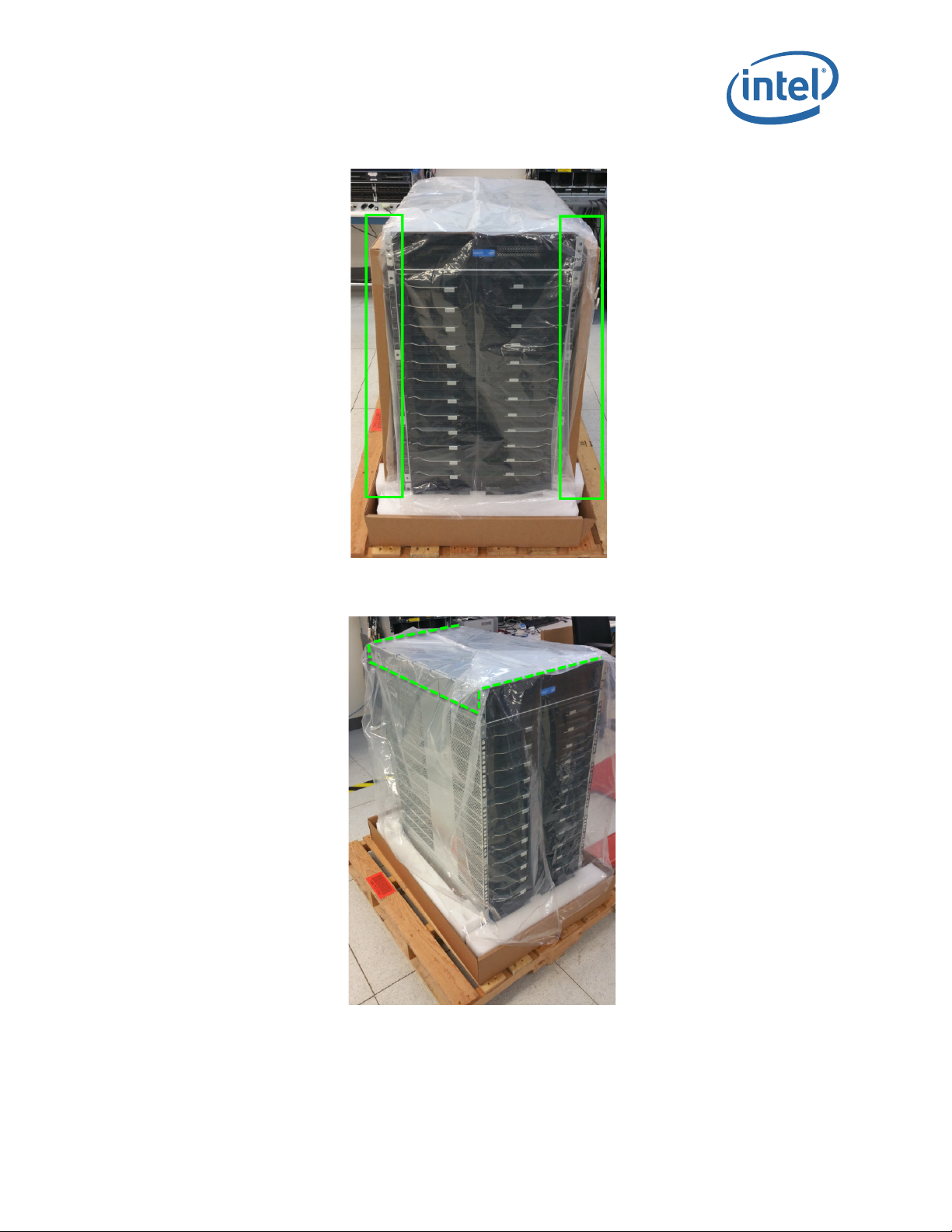
2.4.2 Unpacking the Switch
Note: Set aside packaging materials in the event that the switch requires return shipment.
The following images and descriptions give a high-level overview for unpacking a
Director Switch (24 slot model in this example).
Figure 22. Unpacking the Switch (1)
1. Remove the banding.
®
Omni-Path Fabric Switches
Intel
Installation Guide May 2016
40 Doc. No.: H76456Rev 3.0US
Page 41

Omni-Path Switches
Figure 23. Unpacking the Switch (2)
2. Remove the lid.
Figure 24. Unpacking the Switch (3)
3. Remove the accessory kit box and white packing form. The accessory kit contains
required hardware, power cables, documentation, etc.
May 2016 Installation Guide
Doc. No.: H76456Rev 3.0US 41
Intel® Omni-Path Fabric Switches
Page 42

Figure 25. Unpacking the Switch (4): Accessory Kit
Figure 26. Unpacking the Switch (5)
Omni-Path Switches
4. Lift the box up out of the base.
®
Omni-Path Fabric Switches
Intel
Installation Guide May 2016
42 Doc. No.: H76456Rev 3.0US
Page 43
Omni-Path Switches
Figure 27. Unpacking the Switch (6)
5. Remove the plenum boxes.
Figure 28. Unpacking the Switch (7)
6. Remove the plastic bag, then remove the support shelf from the top of the switch.
May 2016 Installation Guide
Doc. No.: H76456Rev 3.0US 43
Intel® Omni-Path Fabric Switches
Page 44

2.4.3 Installation Tasks
The following section details rack mounting instructions for the 6-slot and 24-slot
®
Intel
Omni-Path Director Class Switch 100 Series. The installations are very similar;
the majority of steps apply to both switches. Where applicable, any specifics for either
the 6-slot or 24-slot Director are called out.
2.4.3.1 Install the Support Platform
1. Measure the inside distance between the front and middle rails on the cabinet (27”
in the Figure 29 example).
Figure 29. Measure the Rack
Omni-Path Switches
2. Before installing into the cabinet, preset the adjustable rails on the plenum base,
leaving the screws loose to the dimension measured on the cabinet (27” in this
example). In order to be able to fit the plenum base into the cabinet, set the rails
to slightly less than the measured size (i.e., < 27”). See Figure 30.
Figure 30. Preset the Adjustable Rails
®
Omni-Path Fabric Switches
Intel
Installation Guide May 2016
44 Doc. No.: H76456Rev 3.0US
Page 45

Omni-Path Switches
3. Install the fixture brackets to the cabinet at the desired height (Figure 31). The
brackets support and help locate the installation of the plenum base. Remove and
discard/recycle the brackets after plenum base has been installed.
Figure 31. Install Fixture Brackets
4. Secure the platform to the rack using M6 mounting screws, 3 per platform rail (1 in
the front and 2 in the back) as displayed in Figure 32. Torque screws to 30in-lb.
Figure 32. Secure Platform to Rack
5. Attach the plenums to the top of each platform rail using 10 mounting nuts, 5 per
platform rail as displayed in Figure 33. Torque nuts to 30in-lb.
Note: Make certain to tighten the adjustable rail screws (from Step 2) at this time.
May 2016 Installation Guide
Doc. No.: H76456Rev 3.0US 45
Intel® Omni-Path Fabric Switches
Page 46

Figure 33. Secure the Plenums to Top of Platform Rails
Omni-Path Switches
6. Secure the top of the plenums to the rack rail as displayed in Figure 34:
a. 6 Slot Chassis: use 2 mounting nuts, 1 per rail.
b. 24 Slot Chassis: use the lower of the 2 openings, 1 mounting nut per rail.
Figure 34. Secure the Top of the Baffles to the Rack Rails
®
Omni-Path Fabric Switches
Intel
Installation Guide May 2016
46 Doc. No.: H76456Rev 3.0US
Page 47

Omni-Path Switches
7. The completed Platform assemblies for both the 6 and 24 slot switches are
displayed in Figure 35.
Figure 35. Completed Platform Assemblies
May 2016 Installation Guide
Doc. No.: H76456Rev 3.0US 47
Intel® Omni-Path Fabric Switches
Page 48

2.4.3.2 Installing the Director Switch Chassis
Omni-Path Switches
Warning: To avoid injury, do not lift a fully-loaded Director class switch manually. Use a
mechanized lift only.
1. Align the chassis with the rack.
2. Using a pallet jack, raise the unit until the bottom of the chassis is at (or slightly
higher than) the surface of the support shelf installed in Steps 1 through 6. Lock
the pallet jack wheels.
3. Use a group of people to push the chassis from the front to slide it off the pallet and
on the support shelf. The chassis should be inserted into the rack until the rear of
the chassis base is against the rear support bracket.
Note: If you are installing the cable management guides (see “Installing the Optional Cable
Management Guide” on page 51), install the cage nuts into the rack rails before fully
sliding the chassis into the rack.
Figure 36. Slide the Chassis into the Rack
®
Omni-Path Fabric Switches
Intel
Installation Guide May 2016
48 Doc. No.: H76456Rev 3.0US
Page 49

Omni-Path Switches
4. Fasten the chassis to the rack with M6 screws:
a. 6-Slot Director: six (6).
b. 24-Slot Director: twelve (12).
Figure 37. Fasten the Chassis to the Rack
May 2016 Installation Guide
Doc. No.: H76456Rev 3.0US 49
Intel® Omni-Path Fabric Switches
Page 50

5. The completed switch installations for both the 6 and 24-slot switches are displayed
in Figure 38.
Figure 38. Completed Switch Installations
Omni-Path Switches
®
Omni-Path Fabric Switches
Intel
Installation Guide May 2016
50 Doc. No.: H76456Rev 3.0US
Page 51

Omni-Path Switches
2.4.4 Installing the Optional Cable Management Guide
The optional Cable Management Guides are attached to the rack rails with M6 cage nuts
and screws as shown in Figure 39.
Figure 39. Installing Cable Management
May 2016 Installation Guide
Doc. No.: H76456Rev 3.0US 51
Intel® Omni-Path Fabric Switches
Page 52

2.4.5 Installing Director Class Modules
Omni-Path Switches
®
Omni-Path Fabric Switches
Intel
Installation Guide May 2016
52 Doc. No.: H76456Rev 3.0US
Page 53

Omni-Path Switches
2.4.5.1 Spine, Leaf and Management Modules
These modules all have release arms that function in a similar way during installation.
The Management Module (MM) is used here as the example.
1. Grasp and pull the release arms out and away from the module body as shown in
Figure 40.
Figure 40. Module Installation 1
May 2016 Installation Guide
Doc. No.: H76456Rev 3.0US 53
Intel® Omni-Path Fabric Switches
Page 54

Figure 41. Module Installation 2
2. Slide the module straight into an applicable open slot until it engages with the
backplane connector.
Omni-Path Switches
Caution: Never push on the release arms when sliding the modules into the applicable slots.
Always apply pressure to the middle of the module as shown in Figure 42.
Figure 42. Module Installation 3
3. Push the release arms in until they lock in place.
4. Management Module only: Lower the MRL latch into the holes of the release
arms. Do the allows the MM to communicate with the SEEB module on the other
side of chassis as shown in Figure 43.
Figure 43. Module Installation 4
®
Omni-Path Fabric Switches
Intel
Installation Guide May 2016
54 Doc. No.: H76456Rev 3.0US
Page 55

Omni-Path Switches
5. Chassis management slot leaf only: If the leaf module is in one of the chassis
management slots (i.e., L101 or L102) the mechanical release latch (MRL) must be
moved in order to install the leaf. To move the MRL, loosen the thumbscrew
attached to the Serial, Ethernet, Chassis EEPROM Board (SEEB) module, then pull
down to release the MRL as shown in Figure 44. This allows enough clearance for
leaf module to be installed.
Figure 44. Module Installation 5
May 2016 Installation Guide
Doc. No.: H76456Rev 3.0US 55
Intel® Omni-Path Fabric Switches
Page 56

2.4.5.2 Fans
1. Slide the fan module straight into an applicable open slot until it engages with the
backplane connector.
Omni-Path Switches
2.4.5.3 Power Supplies
1. Loosen the thumbscrew until it disengages from the power supply unit.
2. Pull the handle down.
3. Slide the module straight into an applicable open slot until it engages with the
backplane connector.
4. Push the handle back up and reconnect the thumbscrew.
®
Omni-Path Fabric Switches
Intel
Installation Guide May 2016
56 Doc. No.: H76456Rev 3.0US
Page 57

Omni-Path Switches
2.5 Connect Equipment to the Ports and Power On the System
Note: Before connecting equipment, it is important to understand the locations of the serial
and Ethernet ports on the Omni-Path Fabric series switches. For the edge switch, these
are located on the switch port side.
Figure 45. Edge Switch Serial and Ethernet Ports
Figure 46. Director Switch Serial and Ethernet Ports
1. Connect a Category 5 or 6 (Cat 5/6) Ethernet cable to the RJ-45 connector(s) on
the switch. Connect the other end of the Cat 5/6 to an OOB LAN workstation,
another switch or a hub.
2. Connect the switch to host(s)/switch(es) using QSFP cables.
Caution: It is important to provide strain relief for the cable connector.
May 2016 Installation Guide
Doc. No.: H76456Rev 3.0US 57
Intel® Omni-Path Fabric Switches
Page 58

2.5.0.1 Edge Switch Cabling Recommendations
To minimize complexity, the following figure details cabling recommendations for the
48-port edge switch:
Figure 47. 48 Port Edge Switch Cabling Recommendations
Omni-Path Switches
2.5.0.2 Connecting Power
Note: For each power supply installed, a power cord must be installed in corresponding power
Note: For the Director switches, make certain the DC ON/OFF switch is illuminated. If it is not,
®
Omni-Path Fabric Switches
Intel
Installation Guide May 2016
58 Doc. No.: H76456Rev 3.0US
inlet.
1. Provide strain relief for the power cable(s).
2. If necessary, replace the closeout over the switch fan side.
3. Connect the power cables to a power distribution unit (PDU) or a proper AC power
outlet.
4. When the switch is plugged into an AC power outlet:
a. The system powers up.
b. The fans start.
c. The system performs a power-on self test.
press the button to supply power. The switch is located in the lower left corner on the
chassis spine side>
5. The switch, power supply(s), and fan LEDs light up.
Page 59

Omni-Path Switches
2.6 Setting Up the USB Console
1. Download the driver file CDM v2.12.00 WHQL Certified.exe from http://
www.ftdichip.com/Drivers/VCP.htm.
2. Open the FTDI Drivers Folder and Right click on the CDMv2.12 driver file and
select Run As Administrator to install the necessary driver to access the USB
serial console of the switch.
3. Open Putty, under Category, select Serial and enter the following parameters:
— Serial Line to connect to: <Enter COM>
— Speed: 115200
— Data Bits: 8
— Stop Bits: 1
— Parity: None
— Flow Control: None
2.7 Bringing Up the System For the First Time
2.7.1 Start-up Procedures
1. Power up the switch.
2. From its flash image on the management module, the switch begins its boot
process.
3. Verify the IP address with the CLI command
system returns information similar to the following:
showChassisIpAddr command. The
Chassis IP Address: 192.168.100.9 Net mask: 255.255.252.0
2.7.2 Changing the Switch IP Address and Default Gateway through the CLI
The CLI can be accessed two ways:
• using the switch serial port:
Edge switch (with optional management module): connects through the USB
—
serial port
Director series: connects through the USB port on the SEEB modules
—
• through Ethernet, using Telnet or SSH
Note: If using a serial port on a Director switch, make certain to connect to the SEEB serial
2.7.2.1 Using the Serial Connection
port associated with the Management Module (MM) on the opposite side of the chassis.
1. When a serial port connection is established, the user will see a prompt. To change
the chassis IP address type:
setChassisIpAddr -h <ipaddress> -m <netMask>
where -h <ipaddress> is the new IP address in dotted decimal format (that is,
xxx.xxx.xxx.xxx), and -m <netMask> is the new subnet mask in dotted
decimal format.
2. To change the switch default gateway IP address type:
setDefaultRoute -h <ipaddress>
May 2016 Installation Guide
Doc. No.: H76456Rev 3.0US 59
Intel® Omni-Path Fabric Switches
Page 60

where -h <ipaddress> is the new default gateway IP address in dotted decimal
format.
3. The changes are effective immediately.
2.7.2.2 Using Ethernet
1. Access the switch with one of the following commands using the default IP address:
Telnet: telnet 192.168.100.9
SSH: ssh 192.168.100.9
2. The system prompts for a user name. In order to change the IP address and default
gateway, the user must be logged in as the administrator. At the prompt type
admin and press ENTER.
3. The system prompts for a password. At the prompt type
ENTER. The system responds with:
Welcome to the <SWITCH> CLI. Type 'list' for the list of
commands.
4. To change the switch IP address type:
setChassisIpAddr -h <ipaddress> -m <netMask>
where -h <ipaddress> is the new IP address in dotted decimal format (that is,
xxx.xxx.xxx.xxx), and -m <netMask> is the new subnet mask in dotted
decimal format.
5. To change the switch default gateway IP address type:
setDefaultRoute -h <ipaddress>
where -h <ipaddress> is the new default gateway IP address in dotted decimal
format.
6. The changes are effective immediately.
Omni-Path Switches
adminpass and press
2.7.3 Updating the Management Module IP Addresses in a Director Class Redundant Management Configuration
Each management module must have a unique IP address that is different than the
chassis IP address of the switch. A redundantly-managed switch will have multiple,
unique IP addresses.The default IP addresses are:
• Chassis: 192.168.100.9
• Management Module 201: 192.168.100.10
• Management Module 202: 192.168.100.11
It is necessary for each management module to have a unique IP address for the
following reasons:
• Unique IP addresses are used when sending syslog messages from a management
module to a syslog server.
• Gives the user the ability to ping each management module separately.
• If the IP addresses are not unique, collisions occur, causing IP operations to fail.
To update the IP address on a management module, do the following:
1. Ensure that the module is connected to a COM port on a serial terminal device
through the USB port.
®
Omni-Path Fabric Switches
Intel
Installation Guide May 2016
60 Doc. No.: H76456Rev 3.0US
Page 61

Omni-Path Switches
2. Get to a [boot]: prompt by following either Step a or b.
3. When the system displays
4. At the
a. If the management module is running and displays the -> prompt, type the
following command at the console:
reboot now
and press ENTER.
b. If the module is not running, power on the switch.
image1 or image2, press the SPACEBAR to interrupt
the auto load sequence before the counter expires (within 5 seconds).
[boot]: prompt type the following:
moduleip <NEW IP ADDRESS>
and press ENTER.
Note: The
module.
5. At the
moduleip command changes the IP address for image1 and image2 on each
[boot]: prompt type reboot, and press ENTER. Following the reboot, the
IP address is changed. Repeat these steps for the second management module.
May 2016 Installation Guide
Doc. No.: H76456Rev 3.0US 61
Intel® Omni-Path Fabric Switches
Page 62

2.8 Component LEDs
2.8.1 Edge Switch
Figure 48. Edge Switch LEDs
2.8.1.1 RJ45 LEDs
Omni-Path Switches
The RJ45 connectors have two LEDs, Link and Speed. The Speed LED is Green when
a 100Mbps link is connected. The Link LED is Amber when an Ethernet link has been
established, and blinking when the link is active.
2.8.1.2 Chassis Status LEDs
2.8.1.2.1 Status (STAT)
The status LED indicates one of the following conditions:
• Steady Green: the module is operating normally.
• Blinking Green: LED test state.
• Off: module is in the removable state.
2.8.1.2.2 Attention (ATTN)
The Attention LED indicates one of the following conditions:
• Off: the system functioning normally.
• Steady Amber: the system requires some attention, which could indicate one of
the following conditions:
— The switch temperature is at a warning level on the module.
— The switch silicon temperature is at a warning level (approximately 90 degrees
C).
— DC voltages on the board are slightly out of tolerance (12V Bulk, 5V, 3.3V and
1.8V are all monitored).
— The module can no longer function properly. The system will take the
appropriate actions to ensure that no damage is done to its components.
• Blinking Amber (once every four seconds): LED test state.
®
Omni-Path Fabric Switches
Intel
Installation Guide May 2016
62 Doc. No.: H76456Rev 3.0US
Page 63

Omni-Path Switches
2.8.1.3 Ports, Fabric Manager (FM), Managed (M), and FM Switch
Figure 49. Ports, Fabric Manager (FM), Managed (M), and FM Switch LEDs
2.8.1.3.1 Ports
Each switch cable port has a Green link status LED that provide the following
indications:
• On: the logical link is up (port is in the Active state).Off: the physical link is down
(port is in the Down state).
2.8.1.3.2 Fabric Manager (FM)
The FM LED indicates that the switch is recognized by the active Fabric Manager.
2.8.1.3.3 Managed (M)
The Managed (M) LED indicates that a Q7 management module is installed switch.
May 2016 Installation Guide
Doc. No.: H76456Rev 3.0US 63
Intel® Omni-Path Fabric Switches
Page 64

2.8.1.3.4 FM Switch
On an unmanaged switch the FM Switch LED is used to restrict whether the end-node
attached to a switch port is allowed to source Fabric Manager-related packets.
The user activates the LED using a small, straight instrument (e.g., a standard-size
paper clip).
Figure 50. Activating the FM Enable Switch LED
Omni-Path Switches
The FM Enable Switch is used as follows:
Note: Actions take place approximately 1 second after releasing the button.
• Pressing the button for 4 seconds does a “Restore Factory Defaults” and reboots
the ASIC
• Pressing the button for 2 seconds (and then releasing) puts the “FM control button
persistent state” in configuration mode
— The FM enabled LED will blink “n” times, where “n” is the current state value
plus 1
— Pressing (and releasing) the button once for less than 2 seconds advances the
FM control persistent state by 1 (round-robin), and then it returns to step 1
(i.e., blinking the FM enabled LED)
— Pressing the button for 2 seconds leaves the configuration state, and saves the
FM control button state persistently, restoring the FM enabled LED to the
proper value
®
Omni-Path Fabric Switches
Intel
Installation Guide May 2016
64 Doc. No.: H76456Rev 3.0US
Page 65

Omni-Path Switches
2.8.1.4 Power Supply LEDs
Figure 51. Power Supply LEDs
PSU1/PSU2:
• Green indicates that DC power is normal.
• Off indicates a DC power failure or no DC power is present.
2.8.1.5 Airflow Direction LED
Figure 52. Airflow Direction LED
• Green indicates the fans are blowing from front to back.
• Off indicates the fans are blowing from back to front.
May 2016 Installation Guide
Doc. No.: H76456Rev 3.0US 65
Intel® Omni-Path Fabric Switches
Page 66

2.8.2 Director Class LEDs
2.8.2.1 Management Module
Figure 53. Management Module LEDs
2.8.2.1.1 Module Status (M_Stat)
The status LED indicates one of the following conditions:
• Steady Green: the module is operating normally.
• Blinking Green: LED test state.
• Off: module is in the removable state.
Omni-Path Switches
2.8.2.1.2 Module Attention (M_Attn)
The Attention LED indicates one of the following conditions:
• Off: the system is functioning normally.
• Steady Amber: the system requires some attention, which could indicate one of
the following conditions:
— The switch temperature is at a warning level
— The switch silicon temperature is at a warning level
— DC voltages on the board are slightly out of tolerance
• Blinking Amber (once every four seconds): LED test state, which could indicate
one of the following conditions:
— Bulk power is stable.
— The module DC-to-DC converter is enabled.
— The module is not removable.
2.8.2.1.3 Chassis Status and Attention (C_Stat, C_Attn)
The chassis status LED is Green when the system is functioning normally.
The chassis status LED is Off when he system is not functioning normally.
2.8.2.1.4 Fault Tolerant (FT)
The Chassis Fault Tolerant (FT) LED indicates the following condition:
• Green: Redundant Cooling, DC Power and management all present (n+1)
• Off: Redundant Cooling, DC Power and management are not all present
®
Omni-Path Fabric Switches
Intel
Installation Guide May 2016
66 Doc. No.: H76456Rev 3.0US
Page 67

Omni-Path Switches
2.8.2.1.5 Service (SVC)
The Chassis Service (SVC) LED indicates the following condition:
• Green: Chassis beacon is active
• Off: Not selected
2.8.2.1.6 Master
• Green: the module is acting as the master Management Module
• Off: Management Module is not the Master
2.8.2.1.7 MRL Active
• Green the mechanical release latch (MRL) thumbscrew is secured to the serial,
Ethernet, chassis EEPROM board (SEEB)
• Off the mechanical release latch (MRL) thumbscrew is not engaged.
2.8.2.2 Leaf Module
Figure 54. Leaf Module LEDs
2.8.2.2.1 Port LEDs
• Green: The external HFI link is in the Active Port State
• Off: Link is not active
2.8.2.2.2 Module Status
The status LED indicates one of the following conditions:
• Steady Green: the module is operating normally.
• Blinking Green: LED test state.
• Off: module is in the removable state.
2.8.2.2.3 Module Attention
The Attention LED indicates one of the following conditions:
May 2016 Installation Guide
Doc. No.: H76456Rev 3.0US 67
Intel® Omni-Path Fabric Switches
Page 68

• Off: the system functioning normally.
• Steady Amber: the system requires some attention, which could indicate one of
the following conditions:
— The switch temperature is at a warning level
— The switch silicon temperature is at a warning level
— DC voltages on the board are slightly out of tolerance
2.8.2.3 Spine Module
Figure 55. Spine Module LEDs
2.8.2.3.1 Module Status (Stat)
Omni-Path Switches
The status LED indicates one of the following conditions:
• Steady Green: the module is operating normally.
• Blinking Green: LED test state.
• Off: module is in the removable state.
2.8.2.4 Module Attention (Attn)
The Attention LED indicates one of the following conditions:
• Off: the system functioning normally.
• Steady Amber: the system requires some attention, which could indicate one of
the following conditions:
— The switch temperature is at a warning level
— The switch silicon temperature is at a warning level
— DC voltages on the board are slightly out of tolerance
• Blinking Amber (once every four seconds): LED test state.
®
Omni-Path Fabric Switches
Intel
Installation Guide May 2016
68 Doc. No.: H76456Rev 3.0US
Page 69

Omni-Path Switches
2.8.2.5 SEEB Module
Figure 56. SEEB Module LEDs
2.8.2.5.1 RJ45 LEDs
The RJ45 connectors have two LEDs, Link and Speed. The Speed LED is Green when
a 100Mbps link is connected. The Link LED is Amber when an Ethernet link has been
established, and blinking when the link is active.
2.8.2.5.2 MRL Active
The MRL Active LED is Green when the mechanical release latch (MRL) thumbscrew is
secured to the serial, Ethernet, Chassis EEPROM Board (SEEB) and a Management
Module is installed in the front of the chassis.
May 2016 Installation Guide
Doc. No.: H76456Rev 3.0US 69
Intel® Omni-Path Fabric Switches
Page 70

2.8.2.6 Fans and Power Supplies
2.8.2.6.1 Fan LEDs
Figure 57. Director Class Fan LEDs
Omni-Path Switches
Fan LEDs indicate the following status(es):
• Green indicates that the fan is functioning properly.
• Amber indicates that the following warning condition exists:
— A single fan failure when the rotation speed is less than 4000 RPM or greater
than 10,950 RPM.
• Green and Amber on indicates a possible problem, including:
— The fan tray is not responding to commands for configuration and temperature-
related operations.
®
Omni-Path Fabric Switches
Intel
Installation Guide May 2016
70 Doc. No.: H76456Rev 3.0US
Page 71

Omni-Path Switches
— A fan is not responding to commands for temperature and speed related
operations.
— The fan speed has fallen below the minimum allowed RPM for a fan.
May 2016 Installation Guide
Doc. No.: H76456Rev 3.0US 71
Intel® Omni-Path Fabric Switches
Page 72

Working page only. Do not distribute.
1.0 Introduction ............................................................................................................. 9
1.1 Intended Audience.............................................................................................. 9
1.2 Related Materials ................................................................................................ 9
1.3 Documentation Conventions............................................................................... 10
1.4 Laser Safety Information ................................................................................... 11
1.5 Electrostatic Discharge Sensitivity (ESDS) Precautions ........................................... 11
1.6 License Agreements .......................................................................................... 11
1.7 Technical Support ............................................................................................. 11
1.8 Safety Information............................................................................................ 12
1.8.1 Statement 1: ........................................................................................ 12
1.8.2 Statement 2: ........................................................................................ 14
1.8.3 Statement 3: ........................................................................................ 16
1.8.4 Statement 4: ........................................................................................ 17
1.8.5 Statement 5: ........................................................................................ 19
1.8.6 Statement 6: ........................................................................................ 21
1.8.7 Statement 7: ........................................................................................ 22
2.0 Installation ............................................................................................................. 25
2.1 Planning the Installation .................................................................................... 25
2.1.1 Cable Requirements ............................................................................... 25
2.1.2 Uninterruptible Power Supply Equipment................................................... 27
2.2 Installation Tasks Checklist ................................................................................ 28
2.2.1 Tools and Equipment Required................................................................. 28
2.2.2 Check the Installation Site ...................................................................... 28
2.2.3 Mark the Rack ....................................................................................... 29
2.3 Omni-Path Fabric Edge Switch Installation............................................................ 30
2.3.1 Mounting Hardware Kit Contents:............................................................. 30
2.3.2 Rack Mounting ...................................................................................... 30
2.3.3 Installing the Airflow Baffles .................................................................... 34
2.3.4 Installing the Switch Fascia ..................................................................... 35
2.3.5 Reversing the Fan Airflow ....................................................................... 35
2.3.6 Installing the Q7 Management Module ...................................................... 38
2.4 Omni-Path Director Class Switches 100 Series Installation...................................... 40
2.4.1 Mounting Hardware Kit Contents:............................................................. 40
2.4.2 Unpacking the Switch ............................................................................. 40
2.4.3 Installation Tasks................................................................................... 44
2.4.4 Installing the Optional Cable Management Guide........................................ 51
2.4.5 Installing Director Class Modules.............................................................. 52
2.5 Connect Equipment to the Ports and Power On the System..................................... 57
2.6 Setting Up the USB Console ............................................................................... 59
2.7 Bringing Up the System For the First Time ........................................................... 59
2.7.1 Start-up Procedures ............................................................................... 59
2.7.2 Changing the Switch IP Address and Default Gateway through the CLI .......... 59
2.7.3 Updating the Management Module IP Addresses in a Director Class
Redundant Management Configuration...................................................... 60
2.8 Component LEDs .............................................................................................. 62
2.8.1 Edge Switch .......................................................................................... 62
2.8.2 Director Class LEDs ................................................................................ 66
72 Intel Confidential
Page 73

Working page only. Do not distribute.
1 Laser Safety Information........................................................................................... 11
2 QSFP Cable Connector Orientation..............................................................................26
3 Copper Cable Bend Radius......................................................................................... 27
4 Fiber Optic Bend Radius ............................................................................................27
5 Omni-Path Edge Switch Rail ...................................................................................... 30
6 Rail Installation Pin .................................................................................................. 31
7 Installed the Rack Rails.............................................................................................31
8 Omni-Path Fabric Edge Switch Mounted in a Four Post Standard Rack .............................32
9 Switch Rail Adjustments............................................................................................ 33
10 Rail Adjustment Notches ........................................................................................... 33
11 Edge Baffle (Top View) gray and yellow both ...............................................................34
12 Secure the Top Baffle to the Switch ............................................................................ 34
13 Switch Fascia .......................................................................................................... 35
14 Rail Posts for Fascia Installation ................................................................................. 35
15 Switch Cover Thumbscrews (Top View) ....................................................................... 36
16 Fan Assembly Rotation ............................................................................................. 36
17 Wire Assembly Strain Relief and Airflow Direction Indicators ..........................................37
18 Q7 Management Module............................................................................................ 38
19 Management Module Slot .......................................................................................... 38
20 Installing the Q7 Module ........................................................................................... 39
21 Q7 Module Mounting Screw .......................................................................................39
22 Unpacking the Switch (1) ..........................................................................................40
23 Unpacking the Switch (2) ..........................................................................................41
24 Unpacking the Switch (3) ..........................................................................................41
25 Unpacking the Switch (4): Accessory Kit .....................................................................42
26 Unpacking the Switch (5) ..........................................................................................42
27 Unpacking the Switch (6) ..........................................................................................43
28 Unpacking the Switch (7) ..........................................................................................43
29 Measure the Rack .................................................................................................... 44
30 Preset the Adjustable Rails ........................................................................................ 44
31 Install Fixture Brackets ............................................................................................. 45
32 Secure Platform to Rack............................................................................................45
33 Secure the Plenums to Top of Platform Rails ................................................................ 46
34 Secure the Top of the Baffles to the Rack Rails............................................................. 46
35 Completed Platform Assemblies .................................................................................47
36 Slide the Chassis into the Rack ..................................................................................48
37 Fasten the Chassis to the Rack .................................................................................. 49
38 Completed Switch Installations ..................................................................................50
39 Installing Cable Management..................................................................................... 51
40 Module Installation 1 ................................................................................................ 53
41 Module Installation 2 ................................................................................................ 54
42 Module Installation 3 ................................................................................................ 54
43 Module Installation 4 ................................................................................................ 54
44 Module Installation 5 ................................................................................................ 55
45 Edge Switch Serial and Ethernet Ports......................................................................... 57
46 Director Switch Serial and Ethernet Ports ....................................................................57
47 48 Port Edge Switch Cabling Recommendations............................................................ 58
48 Edge Switch LEDs ....................................................................................................62
49 Ports, Fabric Manager (FM), Managed (M), and FM Switch LEDs...................................... 63
50 Activating the FM Enable Switch LED ..........................................................................64
51 Power Supply LEDs................................................................................................... 65
52 Airflow Direction LED ................................................................................................65
53 Management Module LEDs......................................................................................... 66
54 Leaf Module LEDs.....................................................................................................67
55 Spine Module LEDs................................................................................................... 68
Intel Confidential 73
Page 74

Working page only. Do not distribute.
56 SEEB Module LEDs................................................................................................... 69
57 Director Class Fan LEDs............................................................................................ 70
74 Intel Confidential
Page 75

Working page only. Do not distribute.
Intel Confidential 75
Page 76

Working page only. Do not distribute.
1 Related Documentation for this Release........................................................................ 9
2 Cable Bend Radius Guidelines.................................................................................... 26
76 Intel Confidential
 Loading...