

Page 1

Global Call API for Host Media Processing on Windows
Programming Guide
August 2006
05-2409-003
Page 2

INFORMATION IN THIS DOCUMENT IS PROVIDED IN CONNECTION WITH INTEL® PRODUCTS. NO LICENSE, EXPRESS OR IMPLIED, BY
ESTOPPEL OR OTHERWISE, TO ANY INTELLECTUAL PROPERTY RIGHTS IS GRANTED BY THIS DOCUMENT. EXCEPT AS PROVIDED IN
INTEL'S TERMS AND CONDITIONS OF SALE FOR SUCH PRODUCTS, INTEL ASSUMES NO LIABILITY WHATSOEVER, AND INTEL DISCLAIMS
ANY EXPRESS OR IMPLIED WARRANTY, RELATING TO SALE AND/OR USE OF INTEL PRODUCTS INCLUDING LIABILITY OR WARRANTIES
RELATING TO FITNESS FOR A PARTICULAR PURPOSE, MERCHANTABILITY, OR INFRINGEMENT OF ANY PATENT, COPYRIGHT OR OTHER
INTELLECTUAL PROPERTY RIGHT. Intel products are not intended for use in medical, life saving, life sustaining, critical control or safety systems, or
nuclear facility applications.
Intel may make changes to specifications and product descriptions at any time, without notice.
This Global Call API for Host Media Processing on Windows Programming Guide as well as the software described in it is furnished under license and
may only be used or copied in accordance with the terms of the license. The information in this manual is furnished for informational use only, is
subject to change without notice, and should not be construed as a commitment by Intel Corporation. Intel Corporation assumes no responsibility or
liability for any errors or inaccuracies that may appear in this document or any software that may be provided in association with this document.
Except as permitted by such license, no part of this document may be reproduced, stored in a retrieval system, or transmitted in any form or by any
means without the express written consent of Intel Corporation.
Copyright © 1996-2005, Intel Corporation
Dialogic, Intel, Intel logo, and Intel NetStructure are trademarks or registered trademarks of Intel Corporation or its subsidiaries in the United States
and other countries.
* Other names and brands may be claimed as the property of others.
Publication Date: August 2006
Document Number: 05-2409-003
Intel
1515 Route 10
Parsippany, NJ 07054
For Technical Support, visit the Intel Telecom Support Resources website at:
http://developer.intel.com/design/telecom/support
For Products and Services Information, visit the Intel Telecom and Compute Products website at:
http://www.intel.com/design/network/products/telecom
For Sales Offices and other contact information, visit the Buy Telecom Products page at:
http://www.intel.com/buy/networking/telecom.htm
Global Call API for HMP on Windows Programming Guide – August 2006
Page 3

Contents
Revision History . . . . . . . . . . . . . . . . . . . . . . . . . . . . . . . . . . . . . . . . . . . . . . . . . . . . . . . . . . . . . 11
About This Publication . . . . . . . . . . . . . . . . . . . . . . . . . . . . . . . . . . . . . . . . . . . . . . . . . . . . . . . 13
Purpose . . . . . . . . . . . . . . . . . . . . . . . . . . . . . . . . . . . . . . . . . . . . . . . . . . . . . . . . . . . . . . . 13
Applicability . . . . . . . . . . . . . . . . . . . . . . . . . . . . . . . . . . . . . . . . . . . . . . . . . . . . . . . . . . . . 13
Intended Audience . . . . . . . . . . . . . . . . . . . . . . . . . . . . . . . . . . . . . . . . . . . . . . . . . . . . . . . 13
How to Use This Publication . . . . . . . . . . . . . . . . . . . . . . . . . . . . . . . . . . . . . . . . . . . . . . . 14
Related Information . . . . . . . . . . . . . . . . . . . . . . . . . . . . . . . . . . . . . . . . . . . . . . . . . . . . . . 14
1 Product Description . . . . . . . . . . . . . . . . . . . . . . . . . . . . . . . . . . . . . . . . . . . . . . . . . . . . . . . . . . 17
1.1 Global Call Software Overview . . . . . . . . . . . . . . . . . . . . . . . . . . . . . . . . . . . . . . . . . . . . . 17
1.2 Global Call Feature Categories . . . . . . . . . . . . . . . . . . . . . . . . . . . . . . . . . . . . . . . . . . . . . 18
1.2.1 Call Control Features . . . . . . . . . . . . . . . . . . . . . . . . . . . . . . . . . . . . . . . . . . . . . . 18
1.2.2 Operation, Administration and Maintenance Features . . . . . . . . . . . . . . . . . . . . . 18
1.3 Global Call Architecture . . . . . . . . . . . . . . . . . . . . . . . . . . . . . . . . . . . . . . . . . . . . . . . . . . . 19
1.3.1 Overview . . . . . . . . . . . . . . . . . . . . . . . . . . . . . . . . . . . . . . . . . . . . . . . . . . . . . . . . 19
1.3.2 Global Call API . . . . . . . . . . . . . . . . . . . . . . . . . . . . . . . . . . . . . . . . . . . . . . . . . . . 21
1.4 Call Control Libraries . . . . . . . . . . . . . . . . . . . . . . . . . . . . . . . . . . . . . . . . . . . . . . . . . . . . . 22
1.4.1 Starting Call Control Libraries . . . . . . . . . . . . . . . . . . . . . . . . . . . . . . . . . . . . . . . . 22
1.4.2 Call Control Library States . . . . . . . . . . . . . . . . . . . . . . . . . . . . . . . . . . . . . . . . . . 22
1.5 Global Call Object Identifiers . . . . . . . . . . . . . . . . . . . . . . . . . . . . . . . . . . . . . . . . . . . . . . . 23
1.5.1 Line Device Identifier . . . . . . . . . . . . . . . . . . . . . . . . . . . . . . . . . . . . . . . . . . . . . . 24
1.5.2 Call Reference Number . . . . . . . . . . . . . . . . . . . . . . . . . . . . . . . . . . . . . . . . . . . . 24
1.5.3 Object Identifiers and Resource Sharing Across Processes . . . . . . . . . . . . . . . . 25
1.5.4 Target Objects . . . . . . . . . . . . . . . . . . . . . . . . . . . . . . . . . . . . . . . . . . . . . . . . . . . 25
2 Programming Models. . . . . . . . . . . . . . . . . . . . . . . . . . . . . . . . . . . . . . . . . . . . . . . . . . . . . . . . . 29
2.1 Programming Models Overview. . . . . . . . . . . . . . . . . . . . . . . . . . . . . . . . . . . . . . . . . . . . . 29
2.2 Asynchronous Mode Programming . . . . . . . . . . . . . . . . . . . . . . . . . . . . . . . . . . . . . . . . . . 29
2.2.1 Asynchronous Model Overview . . . . . . . . . . . . . . . . . . . . . . . . . . . . . . . . . . . . . . 29
2.2.2 Asynchronous Model with Event Handlers . . . . . . . . . . . . . . . . . . . . . . . . . . . . . . 30
2.2.3 Asynchronous with Windows Callback Model. . . . . . . . . . . . . . . . . . . . . . . . . . . . 31
2.2.4 Asynchronous with Win32 Synchronization Model . . . . . . . . . . . . . . . . . . . . . . . . 31
2.2.5 Extended Asynchronous Programming Model . . . . . . . . . . . . . . . . . . . . . . . . . . . 31
3 Call State Models . . . . . . . . . . . . . . . . . . . . . . . . . . . . . . . . . . . . . . . . . . . . . . . . . . . . . . . . . . . . 33
3.1 Call State Model Overview . . . . . . . . . . . . . . . . . . . . . . . . . . . . . . . . . . . . . . . . . . . . . . . . 33
3.2 Basic Call Model . . . . . . . . . . . . . . . . . . . . . . . . . . . . . . . . . . . . . . . . . . . . . . . . . . . . . . . . 33
3.2.1 Basic Call States at the Inbound Interface . . . . . . . . . . . . . . . . . . . . . . . . . . . . . . 34
3.2.2 Basic Call States at the Outbound Interface . . . . . . . . . . . . . . . . . . . . . . . . . . . . . 35
3.2.3 Basic Call States for Call Termination . . . . . . . . . . . . . . . . . . . . . . . . . . . . . . . . . 35
3.3 Basic Call Model Configuration Options . . . . . . . . . . . . . . . . . . . . . . . . . . . . . . . . . . . . . . 36
3.3.1 Call State Configuration . . . . . . . . . . . . . . . . . . . . . . . . . . . . . . . . . . . . . . . . . . . . 36
3.3.2 Call State Event Configuration . . . . . . . . . . . . . . . . . . . . . . . . . . . . . . . . . . . . . . . 37
3.3.3 Call Acknowledgement Configuration. . . . . . . . . . . . . . . . . . . . . . . . . . . . . . . . . . 38
3.3.4 Call Proceeding Configuration . . . . . . . . . . . . . . . . . . . . . . . . . . . . . . . . . . . . . . . 38
Global Call API for HMP on Windows Programming Guide – August 2006 3
Page 4

Contents
3.4 Basic Call Control in Asynchronous Mode . . . . . . . . . . . . . . . . . . . . . . . . . . . . . . . . . . . . . 39
3.4.1 Inbound Calls in Asynchronous Mode . . . . . . . . . . . . . . . . . . . . . . . . . . . . . . . . . . 39
3.4.2 Outbound Calls in Asynchronous Mode . . . . . . . . . . . . . . . . . . . . . . . . . . . . . . . . 52
3.4.3 Call Termination in Asynchronous Mode . . . . . . . . . . . . . . . . . . . . . . . . . . . . . . . . 60
3.4.4 Handling Unsolicited Events . . . . . . . . . . . . . . . . . . . . . . . . . . . . . . . . . . . . . . . . . 64
3.5 Advanced Call Control with Call Hold and Transfer . . . . . . . . . . . . . . . . . . . . . . . . . . . . . . 64
3.5.1 Advanced Call State Model Overview . . . . . . . . . . . . . . . . . . . . . . . . . . . . . . . . . . 64
3.5.2 Advanced Call States for Hold and Transfer . . . . . . . . . . . . . . . . . . . . . . . . . . . . . 65
3.5.3 Call Hold . . . . . . . . . . . . . . . . . . . . . . . . . . . . . . . . . . . . . . . . . . . . . . . . . . . . . . . . 65
3.5.4 Call Transfer . . . . . . . . . . . . . . . . . . . . . . . . . . . . . . . . . . . . . . . . . . . . . . . . . . . . . 66
4 Event Handling . . . . . . . . . . . . . . . . . . . . . . . . . . . . . . . . . . . . . . . . . . . . . . . . . . . . . . . . . . . . . . 71
4.1 Overview of Event Handling . . . . . . . . . . . . . . . . . . . . . . . . . . . . . . . . . . . . . . . . . . . . . . . . 71
4.2 Event Categories . . . . . . . . . . . . . . . . . . . . . . . . . . . . . . . . . . . . . . . . . . . . . . . . . . . . . . . . 71
4.3 Blocked and Unblocked Event Handling. . . . . . . . . . . . . . . . . . . . . . . . . . . . . . . . . . . . . . . 72
4.4 Event Retrieval . . . . . . . . . . . . . . . . . . . . . . . . . . . . . . . . . . . . . . . . . . . . . . . . . . . . . . . . . . 73
4.5 Events Indicating Errors . . . . . . . . . . . . . . . . . . . . . . . . . . . . . . . . . . . . . . . . . . . . . . . . . . .74
4.6 Masking Events . . . . . . . . . . . . . . . . . . . . . . . . . . . . . . . . . . . . . . . . . . . . . . . . . . . . . . . . . 74
4.7 Event Handlers . . . . . . . . . . . . . . . . . . . . . . . . . . . . . . . . . . . . . . . . . . . . . . . . . . . . . . . . . . 74
5 Application Development Guidelines . . . . . . . . . . . . . . . . . . . . . . . . . . . . . . . . . . . . . . . . . . . . 77
5.1 General Programming Tips. . . . . . . . . . . . . . . . . . . . . . . . . . . . . . . . . . . . . . . . . . . . . . . . . 77
5.2 Tips for Programming Drop and Insert Applications . . . . . . . . . . . . . . . . . . . . . . . . . . . . . . 78
5.3 Using Global Call with Digital Network Interface Boards . . . . . . . . . . . . . . . . . . . . . . . . . . 79
5.3.1 Routing Overview . . . . . . . . . . . . . . . . . . . . . . . . . . . . . . . . . . . . . . . . . . . . . . . . . 79
5.3.2 Working with Flexible Routing Configurations . . . . . . . . . . . . . . . . . . . . . . . . . . . . 80
5.3.3 Handling Multiple Call Objects Per Channel in a Glare Condition . . . . . . . . . . . . . 83
6 Error Handling . . . . . . . . . . . . . . . . . . . . . . . . . . . . . . . . . . . . . . . . . . . . . . . . . . . . . . . . . . . . . . . 85
6.1 Error Handling Overview. . . . . . . . . . . . . . . . . . . . . . . . . . . . . . . . . . . . . . . . . . . . . . . . . . . 85
7Call Control . . . . . . . . . . . . . . . . . . . . . . . . . . . . . . . . . . . . . . . . . . . . . . . . . . . . . . . . . . . . . . . . . 87
7.1 Call Progress Analysis when Using IP Technology . . . . . . . . . . . . . . . . . . . . . . . . . . . . . . 87
7.2 Call Progress Analysis when Using Digital Network Interface Boards . . . . . . . . . . . . . . . . 87
7.2.1 Call Progress Analysis Definition . . . . . . . . . . . . . . . . . . . . . . . . . . . . . . . . . . . . . . 87
7.2.2 Configuring Default Call Progress Analysis Parameters . . . . . . . . . . . . . . . . . . . . 88
7.2.3 Configuring Call Progress Analysis on a Per Call Basis . . . . . . . . . . . . . . . . . . . . 88
7.2.4 Setting Call Analysis Attributes on a Per Call Basis . . . . . . . . . . . . . . . . . . . . . . . 90
7.2.5 Configuring Call Progress Analysis on a Per Channel Basis. . . . . . . . . . . . . . . . .91
7.2.6 Setting Call Analysis Attributes on a Per Channel Basis . . . . . . . . . . . . . . . . . . . . 92
7.2.7 Customizing Call Progress Tones on a Per Board Basis . . . . . . . . . . . . . . . . . . . 92
7.3 Resource Routing . . . . . . . . . . . . . . . . . . . . . . . . . . . . . . . . . . . . . . . . . . . . . . . . . . . . . . . . 93
7.4 Feature Transparency and Extension. . . . . . . . . . . . . . . . . . . . . . . . . . . . . . . . . . . . . . . . . 93
7.4.1 Feature Transparency and Extension Overview . . . . . . . . . . . . . . . . . . . . . . . . . . 93
7.4.2 Technology-Specific Feature Access . . . . . . . . . . . . . . . . . . . . . . . . . . . . . . . . . . 94
7.4.3 Technology-Specific User Information. . . . . . . . . . . . . . . . . . . . . . . . . . . . . . . . . . 95
8 Alarm Handling . . . . . . . . . . . . . . . . . . . . . . . . . . . . . . . . . . . . . . . . . . . . . . . . . . . . . . . . . . . . . . 97
8.1 Alarm Handling Overview . . . . . . . . . . . . . . . . . . . . . . . . . . . . . . . . . . . . . . . . . . . . . . . . . . 97
8.1.1 Alarm Management System Components . . . . . . . . . . . . . . . . . . . . . . . . . . . . . . . 97
8.2 Operation and Configuration of GCAMS . . . . . . . . . . . . . . . . . . . . . . . . . . . . . . . . . . . . . . 99
4 Global Call API for HMP on Windows Programming Guide – August 2006
Page 5

Contents
8.2.1 Generation of Events for Blocking Alarms . . . . . . . . . . . . . . . . . . . . . . . . . . . . . . 99
8.2.2 Generation of Alarm Events . . . . . . . . . . . . . . . . . . . . . . . . . . . . . . . . . . . . . . . . 100
8.2.3 Configuration of Alarm Properties and Characteristics . . . . . . . . . . . . . . . . . . . . 101
8.2.4 Starting and Stopping Alarm Transmission. . . . . . . . . . . . . . . . . . . . . . . . . . . . . 104
8.2.5 Retrieving Alarm Data. . . . . . . . . . . . . . . . . . . . . . . . . . . . . . . . . . . . . . . . . . . . . 104
8.3 Sample Alarm Scenarios . . . . . . . . . . . . . . . . . . . . . . . . . . . . . . . . . . . . . . . . . . . . . . . . . 105
8.3.1 Scenario 1: Application Notified of First and Last Blocking Alarm . . . . . . . . . . . 105
8.3.2 Scenario 2: Default Behavior for Alarm Notification . . . . . . . . . . . . . . . . . . . . . . 107
8.3.3 Scenario 3: Alarm Transmission . . . . . . . . . . . . . . . . . . . . . . . . . . . . . . . . . . . . . 108
9 Real Time Configuration Management . . . . . . . . . . . . . . . . . . . . . . . . . . . . . . . . . . . . . . . . . . 109
9.1 Real Time Configuration Manager Overview. . . . . . . . . . . . . . . . . . . . . . . . . . . . . . . . . . 109
9.2 RTCM Components . . . . . . . . . . . . . . . . . . . . . . . . . . . . . . . . . . . . . . . . . . . . . . . . . . . . . 110
9.2.1 Customer Application Using Global Call RTCM . . . . . . . . . . . . . . . . . . . . . . . . . 111
9.2.2 Global Call RTCM . . . . . . . . . . . . . . . . . . . . . . . . . . . . . . . . . . . . . . . . . . . . . . . . 111
9.2.3 RTCM Parameters . . . . . . . . . . . . . . . . . . . . . . . . . . . . . . . . . . . . . . . . . . . . . . . 112
9.3 Using RTCM Parameters. . . . . . . . . . . . . . . . . . . . . . . . . . . . . . . . . . . . . . . . . . . . . . . . . 112
9.3.1 Parameter Dependencies . . . . . . . . . . . . . . . . . . . . . . . . . . . . . . . . . . . . . . . . . . 113
9.3.2 Parameter Definitions . . . . . . . . . . . . . . . . . . . . . . . . . . . . . . . . . . . . . . . . . . . . . 113
9.4 Getting and Setting Parameter Information . . . . . . . . . . . . . . . . . . . . . . . . . . . . . . . . . . . 114
9.4.1 GC_PARM_BLK Data Structure . . . . . . . . . . . . . . . . . . . . . . . . . . . . . . . . . . . . . 114
9.4.2 Control Parameters. . . . . . . . . . . . . . . . . . . . . . . . . . . . . . . . . . . . . . . . . . . . . . . 114
9.5 Handling RTCM Errors . . . . . . . . . . . . . . . . . . . . . . . . . . . . . . . . . . . . . . . . . . . . . . . . . . 117
9.6 Configuration Procedure . . . . . . . . . . . . . . . . . . . . . . . . . . . . . . . . . . . . . . . . . . . . . . . . . 117
9.7 Sample Scenarios Using the RTCM API Functions. . . . . . . . . . . . . . . . . . . . . . . . . . . . . 118
9.7.1 Getting or Setting GCLib Configuration in Synchronous Mode. . . . . . . . . . . . . . 119
9.7.2 Getting or Setting CCLib Configuration in Synchronous Mode. . . . . . . . . . . . . . 120
9.7.3 Getting or Setting Line Device Configuration in Synchronous Mode . . . . . . . . . 121
9.7.4 Setting Line Device Configuration in Asynchronous Mode . . . . . . . . . . . . . . . . . 123
9.7.5 Setting Board Device Configuration in Asynchronous Mode (IP Technology) . . 124
10 Handling Service Requests . . . . . . . . . . . . . . . . . . . . . . . . . . . . . . . . . . . . . . . . . . . . . . . . . . . 127
10.1 Service Request Overview . . . . . . . . . . . . . . . . . . . . . . . . . . . . . . . . . . . . . . . . . . . . . . . 127
10.2 Service Request Components . . . . . . . . . . . . . . . . . . . . . . . . . . . . . . . . . . . . . . . . . . . . . 128
10.3 Service Request Data . . . . . . . . . . . . . . . . . . . . . . . . . . . . . . . . . . . . . . . . . . . . . . . . . . . 129
10.4 General Service Request Scenario . . . . . . . . . . . . . . . . . . . . . . . . . . . . . . . . . . . . . . . . . 129
11 Using Global Call to Implement Call Transfer . . . . . . . . . . . . . . . . . . . . . . . . . . . . . . . . . . . . 131
11.1 Introduction to Call Transfer . . . . . . . . . . . . . . . . . . . . . . . . . . . . . . . . . . . . . . . . . . . . . . 131
11.1.1 Blind Call Transfer . . . . . . . . . . . . . . . . . . . . . . . . . . . . . . . . . . . . . . . . . . . . . . . 131
11.1.2 Supervised Call Transfer . . . . . . . . . . . . . . . . . . . . . . . . . . . . . . . . . . . . . . . . . . 132
11.2 Call Transfer State Machine . . . . . . . . . . . . . . . . . . . . . . . . . . . . . . . . . . . . . . . . . . . . . . 132
12 Building Applications. . . . . . . . . . . . . . . . . . . . . . . . . . . . . . . . . . . . . . . . . . . . . . . . . . . . . . . . 139
12.1 Compiling and Linking . . . . . . . . . . . . . . . . . . . . . . . . . . . . . . . . . . . . . . . . . . . . . . . . . . . 139
12.1.1 Include Files . . . . . . . . . . . . . . . . . . . . . . . . . . . . . . . . . . . . . . . . . . . . . . . . . . . . 139
12.1.2 Required Libraries . . . . . . . . . . . . . . . . . . . . . . . . . . . . . . . . . . . . . . . . . . . . . . . 139
12.1.3 Variables for Compiling and Linking Commands . . . . . . . . . . . . . . . . . . . . . . . . 140
12.1.4 Dynamically Loaded Libraries. . . . . . . . . . . . . . . . . . . . . . . . . . . . . . . . . . . . . . . 140
13 Debugging. . . . . . . . . . . . . . . . . . . . . . . . . . . . . . . . . . . . . . . . . . . . . . . . . . . . . . . . . . . . . . . . . 141
Global Call API for HMP on Windows Programming Guide – August 2006 5
Page 6

Contents
Glossary . . . . . . . . . . . . . . . . . . . . . . . . . . . . . . . . . . . . . . . . . . . . . . . . . . . . . . . . . . . . . . . . . . . 143
Index . . . . . . . . . . . . . . . . . . . . . . . . . . . . . . . . . . . . . . . . . . . . . . . . . . . . . . . . . . . . . . . . . . . . . . 151
6 Global Call API for HMP on Windows Programming Guide – August 2006
Page 7

Contents
Figures
1 Global Call Architecture for IP Technology . . . . . . . . . . . . . . . . . . . . . . . . . . . . . . . . . . . . . . . . 20
2 Global Call Architecture for E1/T1 and ISDN Technologies . . . . . . . . . . . . . . . . . . . . . . . . . . . 21
3 Call Control Library States . . . . . . . . . . . . . . . . . . . . . . . . . . . . . . . . . . . . . . . . . . . . . . . . . . . . . 23
4 Basic Asynchronous Inbound Call State Diagram . . . . . . . . . . . . . . . . . . . . . . . . . . . . . . . . . . . 40
5 Basic Asynchronous Inbound Call Scenario . . . . . . . . . . . . . . . . . . . . . . . . . . . . . . . . . . . . . . . 47
6 Incoming Call Scenario with Call Proceeding . . . . . . . . . . . . . . . . . . . . . . . . . . . . . . . . . . . . . . 48
7 Call Acknowledgement and Call Proceeding Done at the Application Layer. . . . . . . . . . . . . . . 49
8 Call Proceeding Done by the Application Layer with Minimum Information Configured . . . . . . 50
9 Call Acknowledgement and Call Proceeding Done at Technology Call Control Layer . . . . . . . 51
10 Call Acknowledgement Done by the Technology Call Control Layer and Call Proceeding Done by
the Application . . . . . . . . . . . . . . . . . . . . . . . . . . . . . . . . . . . . . . . . . . . . . . . . . . . . . . . . . . . . . . 52
11 Basic Asynchronous Outbound Call State Diagram . . . . . . . . . . . . . . . . . . . . . . . . . . . . . . . . . 54
12 Asynchronous Outbound Call Scenario. . . . . . . . . . . . . . . . . . . . . . . . . . . . . . . . . . . . . . . . . . . 58
13 Asynchronous Outbound Call Scenario With Call Acknowledgement . . . . . . . . . . . . . . . . . . . . 59
14 Asynchronous Outbound Call Scenario With Overlap Sending . . . . . . . . . . . . . . . . . . . . . . . . . 60
15 Asynchronous Call Tear-Down State Diagram . . . . . . . . . . . . . . . . . . . . . . . . . . . . . . . . . . . . . 61
16 User Initiated Asynchronous Call Termination Scenario . . . . . . . . . . . . . . . . . . . . . . . . . . . . . . 62
17 Network Initiated Asynchronous Call Termination Scenario . . . . . . . . . . . . . . . . . . . . . . . . . . . 63
18 Call State Transitions for Hold and Retrieve . . . . . . . . . . . . . . . . . . . . . . . . . . . . . . . . . . . . . . . 66
19 Call State Model for Supervised and Unsupervised Transfers . . . . . . . . . . . . . . . . . . . . . . . . . 68
20 Call Termination by the Network or Application During a Transfer . . . . . . . . . . . . . . . . . . . . . . 69
21 Architectural Diagram of Alarm Management Components . . . . . . . . . . . . . . . . . . . . . . . . . . . 98
22 Notification of First and Last Blocking Alarm . . . . . . . . . . . . . . . . . . . . . . . . . . . . . . . . . . . . . . 106
23 Default Behavior for Alarm Notification . . . . . . . . . . . . . . . . . . . . . . . . . . . . . . . . . . . . . . . . . . 107
24 Alarm Transmission . . . . . . . . . . . . . . . . . . . . . . . . . . . . . . . . . . . . . . . . . . . . . . . . . . . . . . . . . 108
25 Relationship of Customer Application, Global Call RTCM, and RTCM Parameters . . . . . . . . 110
26 Run Time Configuration Procedure . . . . . . . . . . . . . . . . . . . . . . . . . . . . . . . . . . . . . . . . . . . . . 118
27 Getting or Setting GCLib Configuration in Synchronous Mode . . . . . . . . . . . . . . . . . . . . . . . . 119
28 Getting or Setting CCLib Configuration in Synchronous Mode . . . . . . . . . . . . . . . . . . . . . . . . 120
29 Getting or Setting Line Device Configuration in Synchronous Mode. . . . . . . . . . . . . . . . . . . . 122
30 Setting Line Device Configuration in Asynchronous Mode (E1, T1 and ISDN Technology) . . 123
31 Setting Board Device Configuration in Asynchronous Mode (IP Technology). . . . . . . . . . . . . 124
32 Service Request Architecture . . . . . . . . . . . . . . . . . . . . . . . . . . . . . . . . . . . . . . . . . . . . . . . . . 128
33 Generic Service Request Operation . . . . . . . . . . . . . . . . . . . . . . . . . . . . . . . . . . . . . . . . . . . . 130
34 Blind Call Transfer (Unsupervised Transfer) . . . . . . . . . . . . . . . . . . . . . . . . . . . . . . . . . . . . . . 132
35 Supervised Call Transfer . . . . . . . . . . . . . . . . . . . . . . . . . . . . . . . . . . . . . . . . . . . . . . . . . . . . . 132
36 Call State Model for Blind Call Transfer at Party A . . . . . . . . . . . . . . . . . . . . . . . . . . . . . . . . . 134
37 Call State Model for Blind Transfer at Party B . . . . . . . . . . . . . . . . . . . . . . . . . . . . . . . . . . . . . 135
38 Call State Model for Supervised Transfer at Party A . . . . . . . . . . . . . . . . . . . . . . . . . . . . . . . . 136
39 Call State Model for Supervised Transfer at Party B . . . . . . . . . . . . . . . . . . . . . . . . . . . . . . . . 137
40 Call State Model for Supervised Transfer at Party C. . . . . . . . . . . . . . . . . . . . . . . . . . . . . . . . 138
Global Call API for HMP on Windows Programming Guide – August 2006 7
Page 8

Contents
8 Global Call API for HMP on Windows Programming Guide – August 2006
Page 9

Contents
Tables
1 Call Control Library States . . . . . . . . . . . . . . . . . . . . . . . . . . . . . . . . . . . . . . . . . . . . . . . . . . . . . 23
2 Supported Target Types . . . . . . . . . . . . . . . . . . . . . . . . . . . . . . . . . . . . . . . . . . . . . . . . . . . . . . 25
3 Target Types and Target IDs . . . . . . . . . . . . . . . . . . . . . . . . . . . . . . . . . . . . . . . . . . . . . . . . . . . 26
4 Target Object Availability . . . . . . . . . . . . . . . . . . . . . . . . . . . . . . . . . . . . . . . . . . . . . . . . . . . . . . 27
5 Obtaining Target IDs . . . . . . . . . . . . . . . . . . . . . . . . . . . . . . . . . . . . . . . . . . . . . . . . . . . . . . . . . 27
6 Asynchronous Inbound Call State Transitions. . . . . . . . . . . . . . . . . . . . . . . . . . . . . . . . . . . . . . 41
7 Asynchronous Outbound Call State Transitions . . . . . . . . . . . . . . . . . . . . . . . . . . . . . . . . . . . . 55
8 Asynchronous Call Termination Call State Transitions . . . . . . . . . . . . . . . . . . . . . . . . . . . . . . . 61
9 Unsolicited Events Requiring Signal Handlers . . . . . . . . . . . . . . . . . . . . . . . . . . . . . . . . . . . . . 64
10 Handling Glare. . . . . . . . . . . . . . . . . . . . . . . . . . . . . . . . . . . . . . . . . . . . . . . . . . . . . . . . . . . . . . 83
11 Call Progress Analysis Settings and Possible Results . . . . . . . . . . . . . . . . . . . . . . . . . . . . . . . 89
12 Comparison with Call Progress Analysis Using gc_SetParm( ). . . . . . . . . . . . . . . . . . . . . . . . . 92
13 Update Condition Flag and Global Call Process . . . . . . . . . . . . . . . . . . . . . . . . . . . . . . . . . . . 117
14 New Global Call Transfer Call States . . . . . . . . . . . . . . . . . . . . . . . . . . . . . . . . . . . . . . . . . . . 133
Global Call API for HMP on Windows Programming Guide – August 2006 9
Page 10

Contents
10 Global Call API for HMP on Windows Programming Guide – August 2006
Page 11

Revision History
This revision history summarizes the changes made in each published version of this document.
Document No. Publication Date Description of Revisions
05-2409-003 August 2006 Call Control Libraries section: Updated the library descriptions to identify the
technologies/protocols that each library supports.
Using Protocols (Flexible Routing) section: Removed incorrect reference to using the
DM3 PDK Manager.
Setting Call Analysis Attributes on a Per Call Basis section: Updated to indicate that
PAMD_QUAL2TMP is not supported and to provide a pointer to a related Tech
Note.
Debugging chapter : Added reference to the “Runtime Trace Facility (RTF) Reference”
chapter in the Intel Dialogic System Diagnostics Guide.
05-2409-002 October 2005 Global change: Added support for protocols that can be run on the E1 or T1
interfaces provided by Intel NetStructure
Global change: Updates to recognize the Intel NetStructure
Starting Call Control Libraries section : Added note about loading only the required
call control libraries to keep the required memory footprint small.
Overlap Sending section : Explicitly mentioned ISDN in the list of technologies that do
not have messages to request more information.
Configuring Default Call Progress Analysis Parameters section: Added a note that
pre-connect call progress is enabled by default, regardless of the CPA setting in
the CONFIG file
Real Time Configuration Management chapter : Fixed several references to
gc_util_insert_val( ) and gc_util_insert_ref( ) which should be
gc_util_insert_parm_val( ) and gc_util_insert_parm_ref( ).
Supervised Transfers section: Updated the call termination figure and added note to
describe the unsolicited GCEV_CONNECTED event that is generated for a call
when the new call being set up is terminated.
05-2409-001 April 2005 Initial version of document. Much of the information contained in this document was
previously published in the Global Call API for Windows Operating Systems
Programming Guide, document number 05-1867-002.
®
Digital Network Interface boards.
®
brand.
Global Call API for HMP on Windows Programming Guide — August 2006 11
Page 12

Revision History
12 Global Call API for HMP on Windows Programming Guide — August 2006
Page 13

About This Publication
The following topics provide information about this publication:
• Purpose
• Intended Audience
• How to Use This Publication
• Related Information
Purpose
This publication provides guidelines for using the Global Call API to build computer telephony
applications that require call control functionality. Such applications include, but are not limited to,
Call Routing, Enhanced Services, Unified Messaging, Voice Messaging, LAN Telephony Services,
Computer Telephony Services, Switching, PBX, Interactive Voice Response, Help Desk and Work
Flow applications. This publication is a companion guide to the Global Call API Library Reference
that provides details on the functions and parameters in the Global Call API library and the Global
Call Technology Guides that provide IP-, E1/T1- and ISDN-specific information.
Host Media Processing (HMP) software performs media processing tasks on general-purpose
servers based on Intel
system, HMP performs like a virtual DM3 board to the customer application, but all media
processing takes place on the host processor. In this document, the term “board” represents the
virtual DM3 board, unless explictly noted otherwise. Intel NetStructure
boards provide physical E1 and T1 interfaces for applications that require E1/T1 network
connectivity.
®
architecture without the need for specialized hardware. When installed on a
®
Digital Network Interface
Applicability
This document is published for Intel NetStructure® Host Media Processing Software.
Intended Audience
This publication is written for the following audience:
• Distributors
• System Integrators
• Toolkit Developers
• Independent Software Vendors (ISVs)
• Value Added Resellers (VARs)
Global Call API for HMP on Windows Programming Guide — August 2006 13
Page 14

About This Publication
• Original Equipment Manufacturers (OEMs)
How to Use This Publication
Refer to this publication after you have installed the hardware and the system software, which
includes the Global Call software.
This publication assumes that you are familiar with the Windows operating system and the C
programming language.
The information in this guide is organized as follows:
• Chapter 1, “Product Description” provides an overview of the Global Call development
software.
• Chapter 2, “Programming Models” describes the supported programming models in the
Windows environment.
• Chapter 3, “Call State Models” describes the call state models used by Global Call.
• Chapter 4, “Event Handling” describes how to handle Global Call events.
• Chapter 6, “Error Handling” describes the error handling facilities provided by Global Call.
• Chapter 5, “Application Development Guidelines” provides guidelines when developing
applications that use Global Call.
• Chapter 7, “Call Control” describes basic call control capabilities, resource routing and feature
extensions provided by Global Call.
• Chapter 8, “Alarm Handling” describes how Global Call can be used to handle alarms.
• Chapter 9, “Real Time Configuration Management” describes how Global Call can be used for
real time configuration of parameters associated with the interface.
• Chapter 10, “Handling Service Requests” describes the generic service request facility
provided by Global Call.
• Chapter 11, “Using Global Call to Implement Call Transfer” provides general information on
the implementation of unsupervised (blind) and supervised call transfer.
• Chapter 12, “Building Applications” provides guidelines for building applications that use the
Global Call software.
• Chapter 13, “Debugging” provides pointers to where technology-specific debugging
information can be obtained.
• The Glossary provides a definition of terms used in this guide.
Related Information
Refer to the following sources for more information:
• Global Call API Library Reference
• Global Call E1/T1 CAS/R2 Technology Guide
• Global Call ISDN Technology Guide
14 Global Call API for HMP on Windows Programming Guide — August 2006
Page 15

About This Publication
• Global Call IP Technology Guide
• Standard Runtime Library API Programming Guide.
• Standard Runtime Library API Library Reference.
• The Release Update for your HMP software, which may include updates to this manual,
available on the Telecom Support Resources website at:
http://www.intel.com/design/network/products/telecom/software/index.htm
• http://developer.intel.com/design/telecom/support/ (for technical support)
• http://www.intel.com/design/network/products/telecom (for product information)
Global Call API for HMP on Windows Programming Guide — August 2006 15
Page 16

About This Publication
16 Global Call API for HMP on Windows Programming Guide — August 2006
Page 17

1.Product Description
This chapter describes the Global Call software. Topics include:
• Global Call Software Overview. . . . . . . . . . . . . . . . . . . . . . . . . . . . . . . . . . . . . . . . . . . 17
• Global Call Feature Categories . . . . . . . . . . . . . . . . . . . . . . . . . . . . . . . . . . . . . . . . . . . 18
• Global Call Architecture . . . . . . . . . . . . . . . . . . . . . . . . . . . . . . . . . . . . . . . . . . . . . . . . 19
• Call Control Libraries . . . . . . . . . . . . . . . . . . . . . . . . . . . . . . . . . . . . . . . . . . . . . . . . . . 22
• Global Call Object Identifiers . . . . . . . . . . . . . . . . . . . . . . . . . . . . . . . . . . . . . . . . . . . . 23
1.1 Global Call Software Overview
Global Call development software provides a common signaling interface for network-enabled
applications, regardless of the signaling protocol needed to connect to the local telephone network.
The signaling interface provided by Global Call software facilitates the exchange of call control
messages between the telephone network and virtually any network-enabled application. Global
Call software enables developers to create applications that can work with signaling systems
worldwide, regardless of the network to which the applications are connected. The Global Call
software is ideal for high-density, network-enabled solutions, such as voice, data, and video
applications, where the supported hardware and signaling technology can vary widely from country
to country.
1
As an example, the signal acknowledgement or information flow required to establish a call may
vary from country to country. Rather than requiring the application to handle low-level details,
Global Call software offers a consistent, high-level interface to the user and handles each country's
unique protocol requirements transparently to the application.
The Global Call software comprises three major components:
Global Call Application Programming Interface (API)
A common, extensible API providing network interfaces to higher levels of software.
Application developers use API function calls in their computer telephony applications. The
Global Call API is the preferred call control interface.
Call Control Libraries
A set of libraries that provide the interface between the Global Call API and the various
network signaling protocols.
Global Call Protocols
Network signaling protocols, such as T1 Robbed Bit, E1 CAS, ISDN, QSIG, IP H.323 and SIP
can be invoked by the Global Call API to facilitate call control.
Global Call API for HMP on Windows Programming Guide — August 2006 17
Page 18

Product Description
1.2 Global Call Feature Categories
The Global Call development software provides many features allowing for the development of
flexible and robust applications. The features fall into one of two main categories:
• Call Control Features
• Operation, Administration and Maintenance Features
1.2.1 Call Control Features
The Global Call development software provides the following call control features:
Basic Call Control
Includes basic call control features such as, the ability to make a call, detect a call, answer a
call, release a call, etc. The implementation of these capabilities is based on the basic call state
model, which is a common model for all network technologies. See Section 3.2, “Basic Call
Model” for more information on the basic call model.
Advanced Call Model
Defines the behavior for advanced features, such as hold and transfer. These capabilities are
provided to support technologies and protocols that support such features, for example,
Supervised Transfer. The implementation of these capabilities is based on a more advanced
call state model. See Section 3.5, “Advanced Call Control with Call Hold and Transfer” for
more information. The advanced call model applies only to E1/T1 and ISDN technologies, not
IP technology, which uses a different scheme for features such as call transfer. See the Global
Call IP Technology Guide.
Call Progress and Call Analysis
Provides the capabilities for handling pre-connect (Call Progress) information that reports the
status of the call connection, such as, busy, no dial tone or no ringback, and post connect (Call
Analysis) information that reports the destination party’s media type, for example, voice,
answering machine, or fax modem. This information is determined by the detection of tones
defined specifically for this purpose. See Section 7.2, “Call Progress Analysis when Using
Digital Network Interface Boards” for more information. The call progress and call analysis
feature applies only to E1/T1 and ISDN technologies, not IP technology.
Feature Transparency and Extension (FTE)
Provides the ability to extend the capabilities of Global Call to handle features that are specific
to a particular technology so that those features are accessible via the Global Call interface.
For example, for ISDN applications, Global Call supports supplementary services such as
Overlap Send, Overlap Receive, Any Message, Any IE, and User-to-User messaging. See
Section 7.4, “Feature Transparency and Extension” for more information.
1.2.2 Operation, Administration and Maintenance Features
The Global Call development software provides the following features that facilitate the operation,
administration and maintenance of Global Call applications:
Error Handling Functionality
When an error occurs, Global Call provides functions that enable an application to retrieve
more information about the error. See Chapter 6, “Error Handling” for more information.
18 Global Call API for HMP on Windows Programming Guide — August 2006
Page 19

Product Description
Event Handling Functionality
Provides the ability to handle and process events, including the ability to disable and enable
events and to retrieve event information. See Chapter 4, “Event Handling” for more
information.
Global Call Alarm Management System (GCAMS)
Provides the ability to manage alarms. GCAMS provides Global Call applications with the
ability to receive extensive alarm information that can be used to troubleshoot line problems.
See Chapter 8, “Alarm Handling” for more information.
Real Time Configuration Management (RTCM)
Allows the modification of call control and protocol elements in real time, providing a single
common user interface for configuration management. See Chapter 9, “Real Time
Configuration Management” for more information.
Global Call Service Request (GCSR)
Enables an application to send a request for a service to a remote device. Examples of the types
of services that this feature supports are device registration, channel setup, call setup,
information requests, or other kinds of requests that need to be made between two devices
across the network. See Chapter 10, “Handling Service Requests” for more information.
Library Information Functions
Enables an application to get information about the call control libraries being used. See the
Global Call API Library Reference for more information about these functions.
Debugging Facilities
Global Call provides powerful debugging capabilities for troubleshooting protocol-related
problems, including the ability to generate a detailed log file. See the appropriate Global Call
Technology Guide for information on the debugging facilities available when using Global
Call with each technology.
1.3 Global Call Architecture
The Global Call development software architecture is based on the Intel® Dialogic® architecture
that supports Host Media Processing (HMP) software and DM3 hardware. The architecture is
described in the following topics:
• Overview
• Global Call API
1.3.1 Overview
Figure 1 shows a system-level view of the Global Call architecture for IP technology and Figure 2
shows the Global Call architecture for E1/T1 and ISDN technologies on DM3 hardware.
Global Call API for HMP on Windows Programming Guide — August 2006 19
Page 20
Product Description
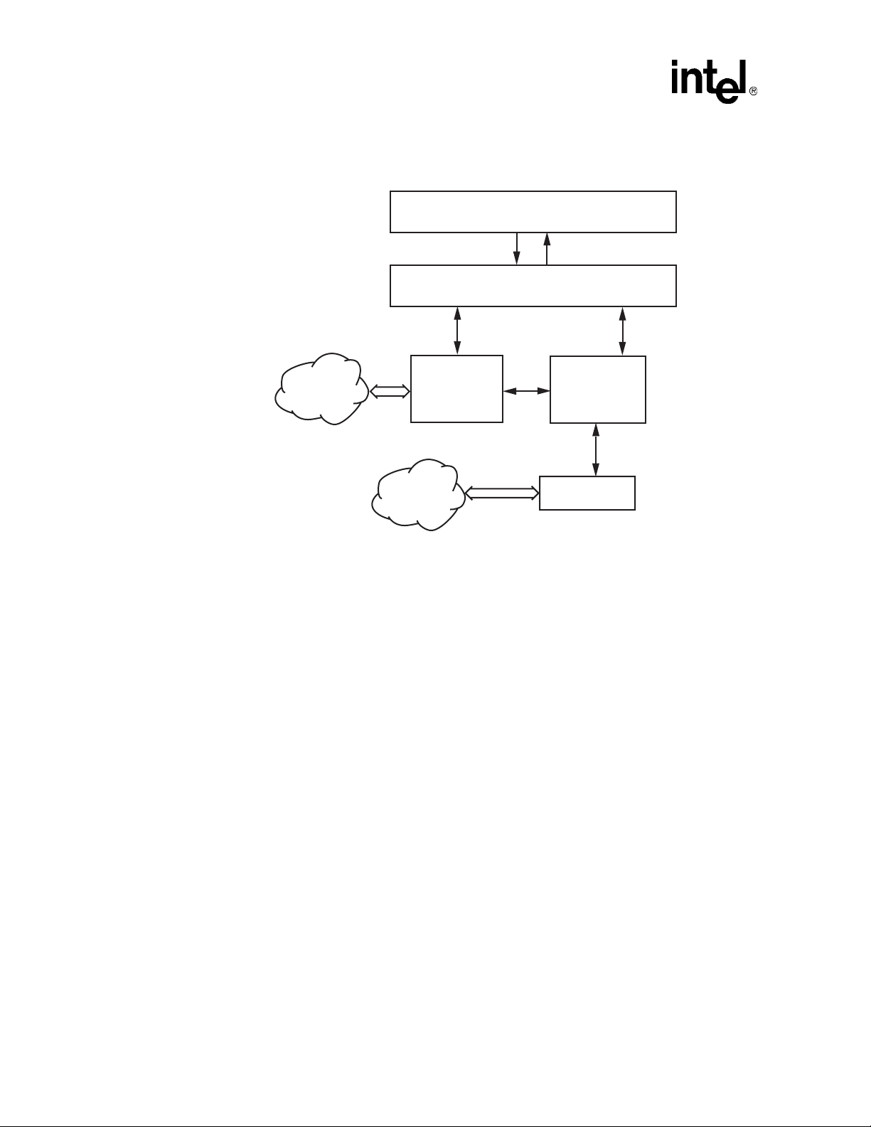
Figure 1. Global Call Architecture for IP Technology
Host Application
GlobalCall
Signaling
IP Network
Call Control
Host
NIC
Media
IP Network
H.323 or SIP
Call Control
Library
(IPT CCLib)
RTP/RTCP
Media
Control
Media
Routing
IP Media
Call Control
Library
(IPM CCLib)
IP Media
Resource
20 Global Call API for HMP on Windows Programming Guide — August 2006
Page 21
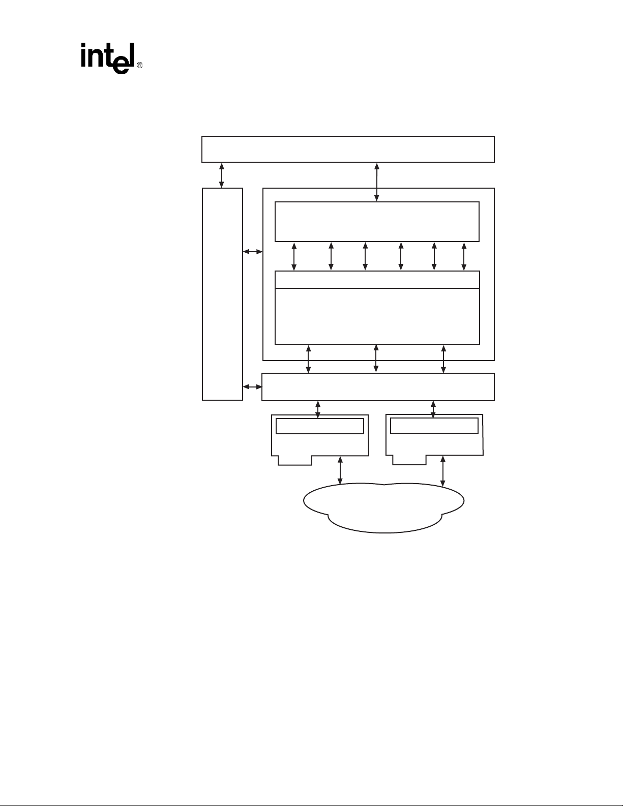
Figure 2. Global Call Architecture for E1/T1 and ISDN Technologies
User Application
GlobalCall API
Product Description
Other
Dialogic
Libraries
1.3.2 Global Call API
Call Control Library
Device Driver Operating Systems
Firmware
Network Interface
DM3CC
Firmware
Network Interface
PSTN
The Global Call API is a call control API. Similar to other Intel Dialogic APIs (such as the Voice
API), the Global Call API uses the Standard Runtime Library (SRL) API to deliver response events
to its API commands. The Global Call API and other Intel Dialogic APIs form a family of APIs
that use the underlying services provided by the SRL API.
The Global Call API provides a collection of functions supporting call control operations as well as
functions to support operation, administration and maintenance tasks. See the Global Call API
Library Reference for detailed information about each function.
Global Call API for HMP on Windows Programming Guide — August 2006 21
Page 22

Product Description
1.4 Call Control Libraries
Each supported network technology requires a call control library to provide the interface between
the network and the Global Call library. The call control libraries currently supported by the
Global Call API for HMP are as follows:
GC_CUSTOM1_LIB
The first of two call control library place holders for custom call control libraries. Any thirdparty Global Call compatible call control library can be used as a custom library. The Global
Call library supports up to two custom libraries.
GC_CUSTOM2_LIB
The second of two call control library place holders for custom call control libraries. Any
third-party Global Call compatible call control library can be used as a custom library. The
Global Call library supports up to two custom libraries.
GC_DM3CC_LIB
The call control library that controls access to network interfaces on Digital Network Interface
boards. This library is used for call control using ISDN and CAS/R2MF (PDK protocols)
signaling on Digital Network Interface boards.
GC_H3R_LIB
The call control library that controls access to IP network interfaces. This call control library
supports IP H.323 and SIP protocols and is used in conjunction with GC_IPM_LIB.
GC_IPM_LIB
The call control library that provides access to IP media resources. This library is used for
H323/SIP call control signaling and is used in conjunction with GC_H3R_LIB.
1.4.1 Starting Call Control Libraries
Call control libraries must be started before they can be used by the Global Call functions. The call
control libraries are started when a gc_Start( ) function is issued. The gc_Start( ) function allows
the selective starting of call control libraries where the application can specify if all the call control
libraries are to be started or only specified libraries are to be started. The application can also start
a custom call control library that is not supported by Global Call. See the Global Call API Library
Reference for more information about the gc_Start( ) function.
Note: Invoking gc_Start(NULL) loads all call control libraries and consequently the memory footprint
includes memory that is allocated for all call control libraries. To reduce the memory footprint,
selective loading of call control libraries is recommended. For more information and an example,
see the gc_Start( ) function in the Global Call API Library Reference.
1.4.2 Call Control Library States
The initial state of all the call control libraries is the Configured state. When a call control library is
successfully started, the library will be in the Available state. If the call control library fails to start,
the library will be in the Failed state as shown in the diagram below. If the call control library is not
started, it remains in the Configured state.
22 Global Call API for HMP on Windows Programming Guide — August 2006
Page 23
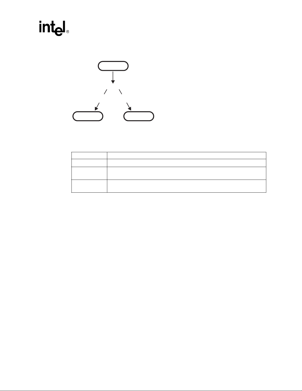
Figure 3. Call Control Library States
CONFIGURED
gc_Start()
Product Description
Start
Successful
AVAILABLE FAILED
Start
Failed
Table 1 describes the different states of a call control library.
Table 1. Call Control Library States
State Description
Configured A library that is supported by Global Call is considered a configured library.
Available A library that has been successfully started is considered to be available for use by a
Global Call application.
Failed A library that has failed to start is considered to be unavailable for use by a Global Call
application.
Each configured call control library is assigned an ID number by Global Call. Each library also has
a name in an ASCII string format. Library functions perform tasks such as converting a call control
library ID to an ASCII name and vice-versa, determining the configured libraries, determining the
available libraries, determining the libraries started and the libraries that failed to start, and other
library functions.
The following functions are the call control library information functions. All the library functions
are synchronous, thus they return without a termination event.
• gc_CCLibIDToName( )
• gc_CCLibNameToID( )
• gc_CCLibStatusEx( )
• gc_GetVer( )
See the Global Call API Library Reference for detailed information about these functions.
1.5 Global Call Object Identifiers
The Global Call API is call-oriented, that is, each call initiated by the application or network is
assigned a Call Reference Number (CRN) for call control and tracking purposes. Call handling is
independent of the line device over which the call is routed. Each line device or device group is
assigned a Line Device Identifier (LDID) that enables the application to address any resource or
Global Call API for HMP on Windows Programming Guide — August 2006 23
Page 24

Product Description
group of resources using a single device identifier. Certain features, such as Feature Transparency
and Extension (FTE), Real Time Configuration Management (RTCM), and Global Call Service
Request (GCSR) operate on a basic entity called a Global Call target object. Target objects are
identified by a target type and a target ID.
The following topics provide more detailed information:
• Line Device Identifier
• Call Reference Number
• Object Identifiers and Resource Sharing Across Processes
• Target Objects
1.5.1 Line Device Identifier
A Line Device Identifier (LDID) is a unique logical number assigned to a specific resource (for
example, a time slot) or a group of resources within a process by the Global Call library. Minimally,
the LDID number will represent a network resource. For example, both a network resource and a
voice resource are needed to process an R2 MFC dialing function. Using Global Call, a single
LDID number is used by the application (or thread) to represent this combination of resources for
call control.
An LDID number is assigned to represent a physical device(s) or logical device(s) that will handle
a call, such as a network interface resource, when the gc_OpenEx( ) function is called. This
identification number assignment remains valid until the gc_Close( ) function is called to close the
line device.
When an event arrives, the application (or thread) can retrieve the LDID number associated with
the event by using the linedev field of the associated METAEVENT structure. The LDID is
retrieved using the gc_GetMetaEvent( ) or the gc_GetMetaEventEx( ) function.
1.5.2 Call Reference Number
A Call Reference Number (CRN) is a means of identifying a call on a specific line device. A CRN
is created by the Global Call library when a call is requested by the application, thread or network.
With the CRN approach, the application (or thread) can access and control the call without any
reference to a specific physical port or line device. CRNs are assigned to both inbound and
outbound calls:
Inbound calls
The CRN is assigned via the gc_WaitCall( ) function. For more information on
gc_WaitCall( ), see the Global Call API Library Reference.
Outbound calls
The CRN is assigned via the gc_MakeCall( ) function. For more information on this function,
see the Global Call API Library Reference.
This CRN has a single LDID associated with it, for example, the line device on which the call was
made. However, a single line device may have multiple CRNs associated with it (that is, more than
24 Global Call API for HMP on Windows Programming Guide — August 2006
Page 25

Product Description
one call may exist on a given line). A line device can have a maximum of 20 CRNs associated with
it. At any given instant, each CRN is a unique number within a process. After a call is terminated
and the gc_ReleaseCallEx( ) function is called to release the resources used for the call, the CRN
is no longer valid.
1.5.3 Object Identifiers and Resource Sharing Across Processes
The CRNs and LDIDs assigned by the Global Call API library can not be shared among multiple
processes. These assigned CRNs and LDIDs remain valid only within the process invoked. That is,
for call control purposes, you should not open the same physical device from more than one
process, nor from multiple threads in a Windows environment. Unpredictable results may occur if
this advice is not followed.
1.5.4 Target Objects
A target object provides a way of identifying a particular entity that is maintained by a specific
software module. In API function calls, the target object is specified by a pair of parameters, the
target_type and target_ID:
target_type
Identifies the kind of software module and the entity that it maintains. For example, the target
type GCTGT_GCLIB_CHAN represents the Global Call Library and a channel entity that it
maintains.
target_ID
Identifies the specific target object, such as a line device ID (LDID), which is generated by
Global Call at runtime.
Table 2 shows the combinations of physical or logical entities and software module entities that can
make up a target type (target_type).
Table 2. Supported Target Types
Software Module
GCLib SSSS
CCLib S S S S
Protocol SV SV SV
Firmware SV SV
S = Supported
SV = Supported with Variances, see the appropriate Global Call Technology Guide for more information.
The possible software modules include:
• GCLib
• CCLib
• Protocol
Entity
System Network Interface Channel CRN
Global Call API for HMP on Windows Programming Guide — August 2006 25
Page 26

Product Description
• Firmware
The possible entities include:
System
NIC for IP technology; all physical boards for E1, T1 and ISDN technologies
Network Interface
logical board or virtual board
Channel
time slot
CRN
call reference number
A target type (target_type) name is composed of the prefix, GCTGT, which stands for Global Call
Target, a software module name, such as GCLIB, and an entity name, such as NETIF. For example,
the target type GCTGT_GCLIB_NETIF, indicates that the desired target type is a network interface
maintained by the Global Call library.
A target ID (target_ID) identifies the specific object that is located within the category defined by
the target type (target_type). A target ID can be any of the following:
• line device ID (LDID)
• call reference number (CRN)
• Global Call library ID (GCGV_LIB)
• call control library ID (CCLib ID)
• protocol ID
The types and IDs for target objects are defined at the Global Call level. Table 3 shows the target
types, as described in Table 2, with various target IDs to represent valid target objects.
Table 3. Target Types and Target IDs
Target Type Target ID Description
GCTGT_GCLIB_SYSTEM
GCTGT_CCLIB_SYSTEM †
GCTGT_GCLIB_NETIF Global Call Line device ID Network interface target object in Global
GCTGT_CCLIB_NETIF Global Call Line device ID Network interface target object in call
GCTGT_GCLIB_CHAN Global Call Line device ID Channel target object in Global Call library
GCTGT_CCLIB_CHAN Global Call Line device ID Channel target object in call control library
† For E1, T1 and ISDN technologies only.
‡ Target types that can only be used by functions issued in synchronous mode. If a function uses one of these target types in
asynchronous mode, an error will be generated. The functions that can use these target types are gc_GetConfigData( ) (E1, T1
and ISDN technologies only), gc_SetConfigData( ), gc_ReqService( ), and gc_RespService( ).
‡ GCGV_LIB Global Call library module target object.
‡ CCLib ID Call control library module target object.
Call Library module.
control library module.
module.
module.
26 Global Call API for HMP on Windows Programming Guide — August 2006
Page 27

Table 3. Target Types and Target IDs (Continued)
Target Type Target ID Description
GCTGT_GCLIB_CRN Global Call CRN CRN target object in Global Call library
GCTGT_CCLIB_CRN Global Call CRN CRN target object in call control library
† For E1, T1 and ISDN technologies only.
‡ Target types that can only be used by functions issued in synchronous mode. If a function uses one of these target types in
asynchronous mode, an error will be generated. The functions that can use these target types are gc_GetConfigData( ) (E1, T1
and ISDN technologies only), gc_SetConfigData( ), gc_ReqService( ), and gc_RespService( ).
Target Object Availability
Except for the GCTGT_GCLIB_SYSTEM target object, all target IDs are generated or assigned by
the Global Call API when the target object is created (for physical targets) or loaded (for software
targets). Table 4 shows when a target object becomes available and when it becomes unavailable,
depending on the target type.
Table 4. Target Object Availability
Product Description
module.
module.
Target Type Target Object Available Target Object Unavailable
GCTGT_GCLIB_SYSTEM
GCTGT_CCLIB_SYSTEM †
GCTGT_GCLIB_CRN
GCTGT_CCLIB_CRN
GCTGT_GCLIB_NETIF
GCTGT_CCLIB_NETIF
GCTGT_GCLIB_CHAN
GCTGT_CCLIB_CHAN
† For E1, T1 and ISDN technologies only.
Retrieving Target IDs
Before the Global Call application can retrieve, update, or query the configuration data of a target
object, it should obtain the target ID as shown in Table 5.
Table 5. Obtaining Target IDs
Target ID Procedure for Obtaining Target ID
GCGV_LIB After the call control library has been successfully started (that is, after the
Global Call Line Device ID † After a line device is opened, the CCLib ID and protocol ID (if applicable)
After gc_Start( ) After gc_Stop( )
After a call is created
(gc_MakeCall( ) returns or
GCEV_OFFERED is received)
After gc_OpenEx( ) After gc_Close( )
gc_Start( ) function is called), the target object’s CCLib ID can be obtained by
calling the gc_CCLibNameToID( ) function.
associated with this line device can be obtained by the gc_GetConfigData( )
function with the set ID and parameter ID as (GCSET_CCLIB_INFO,
GCPARM_CCLIB_ID) and (GCSET_PROTOCOL,
GCPARM_PROTOCOL_ID).
After gc_ReleaseCallEx( )
Global Call API for HMP on Windows Programming Guide — August 2006 27
Page 28

Product Description
Table 5. Obtaining Target IDs
Target ID Procedure for Obtaining Target ID
Global Call CRN After a call target object is created, its target object ID (that is, the Global Call
† For E1, T1 and ISDN technologies only.
CRN) will be an output of the gc_MakeCall( ) function or provided by the
metaevent associated with the GCEV_OFFERED event.
28 Global Call API for HMP on Windows Programming Guide — August 2006
Page 29

2.Programming Models
This chapter describes the programming models supported by Global Call. Topics include:
• Programming Models Overview . . . . . . . . . . . . . . . . . . . . . . . . . . . . . . . . . . . . . . . . . . 29
• Asynchronous Mode Programming. . . . . . . . . . . . . . . . . . . . . . . . . . . . . . . . . . . . . . . . 29
2.1 Programming Models Overview
The Global Call development software supports application development using asynchronous
programming models. By usage, the asynchronous models are often said to use asynchronous
mode. Asynchronous mode programming is introduced briefly in this chapter and described in
more detail in the Standard Runtime Library API Programming Guide.
2.2 Asynchronous Mode Programming
Programming in asynchronous mode in Windows is described in the following topics:
• Asynchronous Model Overview
• Asynchronous Model with Event Handlers
• Asynchronous with Windows Callback Model
• Asynchronous with Win32 Synchronization Model
• Extended Asynchronous Programming Model
2
2.2.1 Asynchronous Model Overview
Asynchronous mode programming is characterized by the calling thread performing other
processing while a function executes. At completion, the application receives event notification
from the SRL and then the thread continues processing the call on a particular channel.
A function called in the asynchronous mode returns control immediately after the request is passed
to the device driver and allows thread processing to continue. A termination event is returned when
the requested operation completes, thus allowing the Intel Dialogic operation (state machine
processing) to continue.
Caution: In general, when a function is called in asynchronous mode, and an associated termination event
exists, the gc_Close( ) function should not be called until the termination event has been received.
In order to disable gc_WaitCall( ), gc_ResetLineDev( ) should be called. If this is not done, there
are potential race conditions under which the application may crash with a segmentation fault.
Functions may be initiated asynchronously from a single thread and/or the completion
(termination) event can be picked up by the same or a different thread that calls the sr_waitevt( )
Global Call API for HMP on Windows Programming Guide — August 2006 29
Page 30

Programming Models
and gc_GetMetaEvent( ) functions. When these functions return with an event, the event
information is stored in the METAEVENT data structure. The event information retrieved
determines the exact event that occurred and is valid until the sr_waitevt( ) and
gc_GetMetaEvent( ) functions are called again.
For Windows environments, the asynchronous models provided for application development also
include:
• asynchronous model with event handlers
• asynchronous with Windows callback
• asynchronous with Win32 synchronization
• extended asynchronous programming
The asynchronous programming models are recommended for more complex applications that
require coordinating multiple tasks. Asynchronous model applications typically run faster than
synchronous models and require lower levels of system resources. Asynchronous models reduce
processor loading because of the reduced number of threads inherent in asynchronous models and
the elimination of scheduling overhead. Asynchronous models use processor resources more
efficiently because multiple channels are handled in a single thread or in a few threads. See
Section 5.1, “General Programming Tips”, on page 77 for details. Of the asynchronous models, the
asynchronous with SRL callback model and the asynchronous with Windows callback model
provide the tightest integration with the Windows message/event mechanism. Asynchronous model
applications are typically more complex than corresponding synchronous model applications due
to a higher level of resource management (that is, the number of channels managed by a thread and
the tracking of completion events) and the development of a state machine.
After the application issues an asynchronous function, the application uses the sr_waitevt( )
function to wait for events on Intel Dialogic devices. All event coding can be accomplished using
switch statements in the main thread. When an event is available, event information may be
retrieved using the gc_GetMetaEvent( ) function. Retrieved event information is valid until the
sr_waitevt( ) function is called again. The asynchronous model does not use event handlers to
process events.
In this model, the SRL handler thread must be initiated by the application by setting the
SR_MODELTYPE value to SR_STASYNC.
2.2.2 Asynchronous Model with Event Handlers
The asynchronous with event handlers model uses the sr_enbhdlr( ) function to automatically
create the SRL handler thread. The application does not need to call the sr_waitevt( ) function
since the thread created by the sr_enbhdlr( ) already calls the sr_waitevt( ) function to get events.
Each call to the sr_enbhdlr( ) function allows the Intel Dialogic events to be serviced when the
operating system schedules the SRL handler thread for execution.
Note: The SR_MODELTYPE value must not be set to SR_STASYNC because the SRL handler thread
must be created by the sr_enbhdlr( ) call. The event handler must not call the sr_waitevt( )
function or any synchronous Intel Dialogic function.
30 Global Call API for HMP on Windows Programming Guide — August 2006
Page 31

Individual handlers can be written to handle events for each channel. The SRL handler thread can
be used when porting applications developed for other operating systems.
2.2.3 Asynchronous with Windows Callback Model
The asynchronous with Windows callback model allows an asynchronous application to receive
SRL event notification through the standard Windows message handling scheme. This model is
used to achieve the tightest possible integration with the Windows messaging scheme. Using this
model, the entire Intel Dialogic portion of the application could be run on a single thread. This
model calls the sr_NotifyEvt( ) function once to define a user-specified application window handle
and a user-specified message type. When an event is detected, a message is sent to the application
window. The application responds by calling the sr_waitevt( ) function with a 0 timeout value. For
Global Call events and optionally for non-Global Call events, the application must then call the
gc_GetMetaEvent( ) function before servicing the event.
In this model, the SRL event handler thread must be initiated by the application by setting the
SR_MODELTYPE value to SR_STASYNC. For detailed information on this programming model,
see the Standard Runtime Library API Programming Guide.
Programming Models
2.2.4 Asynchronous with Win32 Synchronization Model
The asynchronous with Win32 synchronization model allows an asynchronous application to
receive SRL event notification through standard Windows synchronization mechanisms. This
model uses one thread to run all Intel Dialogic devices and thus requires a lower level of system
resources than the synchronous model. This model allows for greater scalability in growing
systems. For detailed information on this programming model, see the Standard Runtime Library
API Programming Guide.
2.2.5 Extended Asynchronous Programming Model
The extended asynchronous programming model is basically the same as the asynchronous model
except that the application uses multiple asynchronous threads, each of which controls multiple
devices. In this model, each thread has its own specific state machine for the devices that it
controls. Thus, a single thread can look for separate events for more than one group of channels.
This model may be useful, for example, when you have one group of devices that provides fax
services and another group that provides interactive voice response (IVR) services, while both
groups share the same process space and database resources. The extended asynchronous model
can be used when an application needs to wait for events from more than one group of devices and
requires a state machine.
Because the extended asynchronous model uses only a few threads for all Intel Dialogic devices, it
requires a lower level of system resources than the synchronous model. This model also enables
using only a few threads to run the entire Intel Dialogic portion of the application.
Global Call API for HMP on Windows Programming Guide — August 2006 31
Page 32

Programming Models
Whereas default asynchronous programming uses the sr_waitevt( ) function to wait for events
specific to one device, extended asynchronous programming uses the sr_waitevtEx( ) function to
wait for events specific to a number of devices (channels).
Note: Do not use the sr_waitevtEx( ) function in combination with either the sr_waitevt( ) function or
event handlers.
This model can run an entire application using only a few threads. When an event is available, the
gc_GetMetaEventEx( ) function must be used to retrieve event-specific information. The values
returned are valid until the sr_waitevtEx( ) function is called again. Event commands can be
executed from the main thread through switch statements; the events are processed immediately.
The extended asynchronous model calls the sr_waitevtEx( ) function for a group of devices
(channels) and polls for (waits for) events specific to that group of devices. In this model, the SRL
event handler thread is not created (the SR_MODELTYPE value is set to SR_STASYNC) and the
sr_enbhdlr( ) function in not used.
In the extended asynchronous model, functions are initiated asynchronously from different threads.
A thread waits for events using the sr_waitevtEx( ) function. The event information can be
retrieved using the gc_GetMetaEventEx( ) function. When this function returns, the event
information is stored in the METAEVENT data structure.
Caution: When calling the gc_GetMetaEventEx( ) function from multiple threads, ensure that your
application uses unique thread-related METAEVENT data structures (thread local variables or
local variables), or ensure that the METAEVENT data structure is not overwritten until all
processing of the current event has completed.
The event information retrieved determines the exact event that occurred and is valid until the
sr_waitevtEx( ) function returns with another event.
32 Global Call API for HMP on Windows Programming Guide — August 2006
Page 33

3.Call State Models
This chapter describes the call state models provided by Global Call. Topics include the following:
• Call State Model Overview . . . . . . . . . . . . . . . . . . . . . . . . . . . . . . . . . . . . . . . . . . . . . . 33
• Basic Call Model . . . . . . . . . . . . . . . . . . . . . . . . . . . . . . . . . . . . . . . . . . . . . . . . . . . . . . 33
• Basic Call Model Configuration Options . . . . . . . . . . . . . . . . . . . . . . . . . . . . . . . . . . . 36
• Basic Call Control in Asynchronous Mode. . . . . . . . . . . . . . . . . . . . . . . . . . . . . . . . . . 39
• Advanced Call Control with Call Hold and Transfer . . . . . . . . . . . . . . . . . . . . . . . . . . 64
3.1 Call State Model Overview
Global Call maintains a generic call model from which technology-specific call models can be
derived. Some technologies support only a subset of the complete call model. The call
establishment and termination procedures are based on this call model. The following sections
describe the call states associated with the basic call model and configuration options.
3.2 Basic Call Model
3
Each call received or generated by Global Call is processed through a series of states, where each
state represents the completion of certain tasks or the current status of the call. Some states in the
basic call model are optional and can be enabled or disabled selectively. Only the optional states
can be enabled or disabled. Every technology or call control library has a default call state model
consisting of all the states it can possibly support from the basic call model. If a state is disabled, all
corresponding events are disabled. If a state is enabled, all corresponding events are enabled.
The call states change in accordance with the sequence of functions called by the application and
the events that originate in the network and system hardware. The current state of a call can be
changed by:
• Function call returns
• Termination events (indications of function completion)
• Unsolicited events
The states of the basic call model are described in the following sections:
• Basic Call States at the Inbound Interface
• Basic Call States at the Outbound Interface
• Basic Call States for Call Termination
Global Call API for HMP on Windows Programming Guide — August 2006 33
Page 34

Call State Models
3.2.1 Basic Call States at the Inbound Interface
The basic inbound call states are as follows:
Null state (GCST_NULL)
This state indicates that no call is assigned to the channel (time slot or line). This is the initial
state of a channel when it is first opened. This state is also reached when a call is released or
after the channel is reset. A channel in this state is available for inbound calls after being
initialized to receive incoming calls.
Call Detected (GCST_DETECTED)
An incoming call has been received but not yet offered to the application. In this state, the call
is being processed, which typically involves waiting for more information or allocating a
resource. Although the call is not yet offered to the application, this state is for informational
purposes to reduce glare conditions since the application is aware of the presence of a call on
the channel.
Call Offered (GCST_OFFERED)
This state exists for an incoming call when the user application has received a call
establishment request but has not yet responded. The newly arrived inbound call is offered to
the user application to be accepted, answered, rejected, etc. Call information is typically
available at this time to be examined so that the application can determine the appropriate
action to take with regards to the call.
Get More Information (GCST_GETMOREINFO)
This state exists for an incoming call when the network has received an acknowledgement of
the call establishment request, which permits the network to send additional call information
(if any) in the overlap mode. The application is waiting for more information, typically called
party number digits. (This state is optional and may not be supported in all technologies. See
the appropriate Global Call Technology Guide for information.) This state applies to E1, T1
and ISDN technologies only.
Call Routing (GCST_CALLROUTING)
This state exists for an incoming call when the user has sent an acknowledgement that all call
information necessary to effect call establishment has been received. The acknowledgement
can be sent from the Offered or the GetMoreInfo state if all the information has been received.
This transition typically involves the sending of Call Routing tones or technology specific
messages; for example, in the case of ISDN, a CALL_PROCEEDING message is sent. The
application can now accept or answer the call. (This state is optional and may not be supported
in all technologies. See the appropriate Global Call Technology Guide for information.)
Call Accepted (GCST_ACCEPTED)
This state indicates that the incoming call was offered and accepted by the application. The
user on the inbound side has indicated to the calling party that the destination user is alerting or
ringing but has not yet answered.
Call Connected (GCST_CONNECTED)
This is a common state that exists for an incoming call when the user has answered the call.
34 Global Call API for HMP on Windows Programming Guide — August 2006
Page 35

3.2.2 Basic Call States at the Outbound Interface
The basic outbound call states are as follows:
Null state (GCST_NULL)
This state indicates that no call is assigned to the channel (time slot or line). This is the initial
state of a channel when it is first opened. This state is also reached when a call is released or
after the channel is reset. The channel in this state is available for making outbound calls.
Call Dialing (GCST_DIALING)
This state exists for an outgoing call when an outbound call request is made. The call signaling
or message is in the process of being prepared for transfer or being transferred across the
telephony network. In response, the remote side may request more information,acknowledge
the call, accept the call or answer the call.
Send More Information (GCST_SENDMOREINFO)
This state exists for an outgoing call when the user has received an acknowledgement of the
call establishment request that permits or requests the user to send additional call information
to the network in overlap mode. The information, typically digits, is in the process of being
prepared for transfer or being transferred across the telephony network (overlap sending or
partial dialing). (This state is optional and may not be supported in all technologies. See the
appropriate Global Call Technology Guide for information.) This state applies to E1, T1 and
ISDN technologies only.
Call State Models
Call Proceeding (GCST_PROCEEDING)
This state exists for an outgoing call when the user has received an acknowledgement that all
call information necessary to effect call establishment has been received and the call is
proceeding. The remote side can now accept or answer the call. (This state is optional and may
not be supported in all technologies. See the appropriate Global Call Technology Guide for
information.)
Call Alerting (GCST_ALERTING)
This state exists for an outgoing call when the calling user has received an indication that
remote user alerting has been initiated, typically ringing. The outbound call has been delivered
to the remote party, which has not yet answered the call.
Call Connected (GCST_CONNECTED)
This is a common state that exists for an outgoing call when the user has received an indication
that the remote user has answered the call. The calling and called parties are connected and the
call is therefore active on the related call channel.
3.2.3 Basic Call States for Call Termination
The basic call termination states are as follows:
Call Disconnected (GCST_DISCONNECTED)
This state indicates that the remote party has disconnected the call. The remote party can
disconnect the call prior to establishing a connection, that is, while the call setup is in progress.
Thus, the call does not have to be in the connected state before it can be disconnected. The user
must respond by dropping the call and releasing the internal resources allocated for the call.
Global Call API for HMP on Windows Programming Guide — August 2006 35
Page 36

Call State Models
Call Idle (GCST_IDLE)
This state indicates that the local user has dropped the call. This may be a termination initiated
by the local user or a response to the remote side disconnecting the call. While the call no
longer exists, internal system resources committed to servicing the call are still present. The
user must release these resources, as they are no longer required.
3.3 Basic Call Model Configuration Options
Depending on the specific technology, the following options are available for configuring the
technology call control layer or the application:
Call State
If a state is disabled, the corresponding call state event is also disabled.
Call State Event
Call state transition events are masked so that the events are not generated.
Call Acknowledgement
An acknowledgement is sent to indicate to the remote side that the call has been received but
more information is required to proceed with the call.
Call Proceeding
Call proceeding information is sent to the remote side when an incoming call is received and
all the information required to proceed with the call is available.
Minimum Information
A minimum amount of destination address information, such as DNIS, is collected before the
call is offered to the application.
3.3.1 Call State Configuration
Some states in the basic call model are optional and can be enabled or disabled selectively. Every
technology or call control library has a default call state model consisting of all the states it can
possibly support from the basic call model. If a state is disabled, the corresponding call state event
will also be disabled. If a state is enabled, the event mask setting still determines which call state
events are sent to the application.
This configuration can be done by issuing the gc_SetConfigData( ) function with a target_type of
GCTGT_GCLIB_CHAN and a target_ID of a line device, and passing the appropriate set ID and
parameter IDs. The set ID used in this context is GCSET_CALLSTATE_MSK and the relevant
parameter IDs are:
GCACT_ADDMSK
Enable the call states specified in the value in addition to other states already enabled.
GCACT_SUBMSK
Disable all the call states specified in the value.
GCACT_SETMSK
Enable the call states specified in the value and disable other optional states that are already
enabled.
36 Global Call API for HMP on Windows Programming Guide — August 2006
Page 37

The GCACT_ADDMSK, GCACT_SUBMSK and GCACT_SETMSK parameter IDs can be
assigned one of the following values (of type GC_VALUE_LONG), or an ORed combination of
the values:
• GCMSK_ALERTING_STATE
• GCMSK_CALLROUTING_STATE (for E1, T1, and ISDN technologies only)
• GCMSK_DETECTED_STATE
• GCMSK_GETMOREINFO_STATE (for E1, T1, and ISDN technologies only)
• GCMSK_PROCEEDING_STATE
• GCMSK_SENDMOREINFO_STATE (for E1, T1, and ISDN technologies only)
See the Global Call API Library Reference for more information on the gc_SetConfigData( )
function.
3.3.2 Call State Event Configuration
Some call state transition events can be masked so that the events are not generated. Although an
event may be masked, the corresponding call state transition can still take place. This configuration
can be done by issuing the gc_SetConfigData( ) function with a target_type of
GCTGT_GCLIB_CHAN and a target_ID of a line device, and passing the appropriate set ID and
parm IDs.
Call State Models
The set ID used in this context is GCSET_CALLEVENT_MSK and the relevant parm IDs are:
GCACT_ADDMSK
Enable the notification of events specified in the value in addition to previously enabled
events.
GCACT_SUBMSK
Disable notification of the events specified in the value.
GCACT_SETMSK
Enable the notification of events specified in the value and disables notification of any event
not specified.
The GCACT_ADDMSK, GCACT_SUBMSK and GCACT_SETMSK parm IDs can be assigned
one of the following values (of type GC_VALUE_LONG), or an ORed combination of the values:
• GCMSK_ALERTING
• GCMSK_DETECTED
• GCMSK_DIALING
• GCMSK_PROCEEDING
• GCMSK_REQMOREINFO (for E1, T1, and ISDN technologies only)
Note: Using the gc_SetConfigData( ) function with a target_ID of a board device to mask events for all
devices associated with a board is not supported. Call state events can be masked on a per line
device basis only.
Global Call API for HMP on Windows Programming Guide — August 2006 37
Page 38

Call State Models
See the Global Call API Library Reference for more information on the gc_SetConfigData( )
function.
3.3.3 Call Acknowledgement Configuration
Note: This functionality applies to E1, T1 and ISDN technologies only.
When an incoming call is received, an acknowledgement is typically sent to the remote side to
indicate that the call was received. In some technologies, if the incoming call does not have
sufficient information, this acknowledgement also indicates to the remote side that more
information is required to proceed with the call (see Section 3.4.1.8, “Overlap Receiving” for more
information). Either the technology call control layer or the application can be configured to send
the acknowledgement. This configuration can be set by the application issuing the
gc_SetConfigData( ) function. The set ID used in this context is GCSET_CALL_CONFIG and the
relevant parm ID is:
GCPARM_CALLACK
Specify whether call acknowledgement is provided by the application or the technology call
control layer.
The GCPARM_CALLACK parm ID can be assigned one of the following values (of type
GC_VALUE_INT):
• GCCONTROL_APP (application controlled)
• GCCONTROL_TCCL (technology call control layer controlled)
See the Global Call API Library Reference for more information on the gc_SetConfigData( )
function.
3.3.4 Call Proceeding Configuration
When an incoming call is received and all the information required to proceed with the call is
available, an indication that the call is proceeding is usually sent to the remote side for
informational purposes. Either the technology call control layer or the application can be
configured to send a call proceeding indication to the remote side. This can be done by issuing the
gc_SetConfigData( ) function. The set ID used in this context is GCSET_CALL_CONFIG and the
relevant parm ID is:
GCPARM_CALLPROC
Specify whether call proceeding indication is provided by the application or the technology
call control layer.
The GCPARM_CALLPROC parm ID can be assigned one of the following values (of type
GC_VALUE_INT):
• GCCONTROL_APP (application controlled)
• GCCONTROL_TCCL (technology call control layer controlled)
See the Global Call API Library Reference for more information on the gc_SetConfigData( )
function.
38 Global Call API for HMP on Windows Programming Guide — August 2006
Page 39

Call State Models
3.4 Basic Call Control in Asynchronous Mode
This section describes and illustrates the basic call model and state transitions for call control in
asynchronous mode. This section also describes the process for call establishment for both inbound
and outbound calls and call termination in the asynchronous mode.
The procedures for establishing and terminating calls in the asynchronous mode are described in
the following sections:
• Inbound Calls in Asynchronous Mode
• Outbound Calls in Asynchronous Mode
• Call Termination in Asynchronous Mode
Note: For E1, T1 and ISDN technologies, the Advanced Call Model includes call states associated with
holding, retrieving and transferring calls. See Section 3.5, “Advanced Call Control with Call Hold
and Transfer” for more information.
Caution: In general, when a function is called in asynchronous mode, and an associated termination event
exists, the gc_Close( ) function should not be called until the termination event has been received.
Otherwise, the behavior is undefined.
3.4.1 Inbound Calls in Asynchronous Mode
This section describes how calls are established and shows call scenarios for asynchronous inbound
calls. The following topics describe the processing of inbound calls in asynchronous mode:
• Inbound Calls in Asynchronous Mode Overview
• Channel Initialization
• Call Detection
• Call Offered
• Call Routing
• Call Acceptance
• Call Establishment
• Overlap Receiving (for E1, T1, and ISDN technologies only)
• Call Failure
• Abandoned Calls
• Inbound Call Scenarios in Asynchronous Mode
3.4.1.1 Inbound Calls in Asynchronous Mode Overview
Figure 4 illustrates a Basic Inbound Call Model, which shows the call states associated with
establishing a call in asynchronous mode. All calls start from a Null state. The call establishment
process for inbound calls is shown in Figure 4.
See Table 6, “Asynchronous Inbound Call State Transitions”, on page 41 for a summary of the call
state transitions.
Global Call API for HMP on Windows Programming Guide — August 2006 39
Page 40

Call State Models
Figure 4. Basic Asynchronous Inbound Call State Diagram
gc_WaitCall()
(called only once)
NULL
GCEV_DETECTED
(maskable)
GetMoreInfo
gc_ReqMoreInfo()
GCEV_MOREINFO
gc_AnswerCall()
GCEV_ANSWERED
CONNECTED
Legend:
Required
Optional
DETECTED
GCEV_OFFERED
gc_CallAck(MORE_INFO)
GCEV_MOREINFO
gc_CallAck(CALL_PROC)
GCEV_CALLPROC
gc_AcceptCall()
GCEV_ACCEPT
gc_AnswerCall()
GCEV_ANSWERED
GCEV_OFFERED
OFFERED
gc_CallAck(CALL_PROC)
GCEV_CALLPROC
CallRouting
gc_AcceptCall()
GCEV_ACCEPT
gc_AcceptCall()
GCEV_ACCEPT
ACCEPTED
gc_AnswerCall()
GCEV_ANSWERED
Note: In Figure 4, the GetMoreInfo state and all transitions to/from that state apply to E1, T1, and ISDN
technologies only.
40 Global Call API for HMP on Windows Programming Guide — August 2006
Page 41

Table 6. Asynchronous Inbound Call State Transitions
Call State Models
State Description Previous/Next State
Accepted
(GCST_ACCEPTED)
Maskable
Call Routing
(GCST_CALLROUTING)
Maskable
Connected
(GCST_CONNECTED)
Not Maskable
Detected
(GCST_DETECTED)
Maskable
GetMoreInfo
(GCST_GETMOREINFO) †
Maskable
Previous: Offered,
GetMoreInfo †,
CallRouting
Next:
GCEV_ANSWERED ->
Connected state
GCEV_DISCONNECTED ->
Disconnected state
GCEV_DROP CALL -> Idle
state
Previous: Offered,
GetMoreInfo †
Next:
GCEV_ANSWERED ->
Connected state
GCEV_ACCEPT ->
Accepted state
GCEV_DISCONNECTED ->
Disconnected state
GCEV_DROPCALL ->
Idle state
Previous: Accept, Offered,
GetMoreInfo †,CallRouting,
Dialing, SendMoreInfo
†,Proceeding, Alerting
Next:
GCEV_DISCONNECTED ->
Disconnected state
GCEV_DROPCALL -> Idle
state
Previous: Null
Next:
GCEV_OFFERED -> Offered
state
GCEV_DISCONNECTED ->
Disconnected state
GCEV_DROPCALL -> Idle
state
Previous: Offered
Next:
GCEV_ANSWERED ->
Connected state
GCEV_MOREINFO ->
GetMoreInfo state
GCEV_ACCEPT ->
Accepted state
GCEV_CALLPROC ->
CallRouting state
GCEV_DISCONNECTED ->
Disconnected state
GCEV_DROPCALL ->
Idle state
† Applies to E1, T1 and ISDN technology only.
Valid Call State
Tra nsiti on
Call Transition Events
Functions
gc_AnswerCall( ),
gc_DropCall( )
gc_AnswerCall( ),
gc_AcceptCall( ),
gc_DropCall( )
gc_DropCall( ) GCEV_DISCONNECTED
gc_DropCall( ) GCEV_DISCONNECTED,
gc_ReqMoreInfo( ),
gc_CallAck( )
gc_AnswerCall( ),
gc_AcceptCall( ),
gc_DropCall( )
,
GCEV_DISCONNECTED,
GCEV_DROPCALL or
GCEV_ANSWERED
GCEV_DISCONNECTED,
GCEV_DROPCALL,
GCEV_ACCEPT or
GCEV_ANSWERED
GCEV_DROPCALL
GCEV_DROPCALL,
GCEV_OFFERED,
GCEV_DISCONNECTED,
GCEV_DROPCALL,
GCEV_ACCEPT,
GCEV_ANSWERED,
GCEV_MOREINFO or
GCEV_CALLPROC
Global Call API for HMP on Windows Programming Guide — August 2006 41
Page 42

Call State Models
Table 6. Asynchronous Inbound Call State Transitions
State Description Previous/Next State
Null (GCST_NULL)
Not Maskable
Offered (GCST_OFFERED)
Not Maskable
† Applies to E1, T1 and ISDN technology only.
Previous: Idle
Next: gc_WaitCall( ) ->
Null state
gc_ResetLineDev( ) ->
Null state
GCEV_OFFERED ->
Offered state
GCEV_DETECTED ->
Detected state
Previous: Null, Detected
Next:
GCEV_ANSWERED ->
Connected state
GCEV_ACCEPT ->
Accepted state
GCEV_CALLPROC ->
CallRouting state
GCEV_MOREINFO ->
GetMoreInfo state †
GCEV_DISCONNECTED ->
Disconnected state
GCEV_DROPCALL ->
Idle state
Valid Call State
Transition
Functions
gc_WaitCall( ) GCEV_DETECTED,
gc_CallAck( ),
gc_AnswerCall( ),
gc_AcceptCall( ),
gc_DropCall( )
Call Transition Events
GCEV_OFFERED
GCEV_DISCONNECTED,
GCEV_DROPCALL,
GCEV_ACCEPT,
GCEV_ANSWERED,
GCEV_MOREINFO †,
GCEV_CALLPROC
The following sections describe the asynchronous inbound call processes.
3.4.1.2 Channel Initialization
To establish calls, the following conditions must be met:
• The condition of the line device must be unblocked. When a channel is initially opened, the
initial condition of a line device is blocked. A “blocking” condition on a line device is
indicated by the reception of a GCEV_BLOCKED event and an “unblocking” condition on a
line device is indicated by the reception of a GCEV_UNBLOCKED event. The
GCEV_BLOCKED and GCEV_UNBLOCKED events are sent as unsolicited events to the
application in response to blocking alarms. GCEV_BLOCKED and GCEV_UNBLOCKED
events are related to layer 1 alarms, as well as to channel states (service status in T1 ISDN, bit
states in CAS). GCEV_BLOCKED and GCEV_UNBLOCKED are used as what might be
termed flow-control events within the application. For more information on blocking alarms
and the GCEV_BLOCKED and GCEV_UNBLOCKED events, see Section 4.3, “Blocked and
Unblocked Event Handling”. When the condition of the line device is unblocked, the line
device is ready for establishing calls.
• The call state of the channel must be in the Null state. This is the initial call state of a line
device when it is first opened. This state is also reached when a call is released or after the
channel is reset.
If the above conditions are met, the application or thread must issue a gc_WaitCall( ) function in
the Null state to indicate readiness to accept an inbound call request on the specified line device. In
the asynchronous mode, the gc_WaitCall( ) function must be called only once after the line device
42 Global Call API for HMP on Windows Programming Guide — August 2006
Page 43

is opened using the gc_OpenEx( ) function. However, if the gc_ResetLineDev( ) function was
issued, gc_WaitCall( ) must be reissued. In asynchronous mode, it is not necessary to issue
gc_WaitCall( ) again after a call is released.
Note: After gc_WaitCall( ) is issued to wait for incoming calls on a line device, it is possible to use
gc_makeCall( ) to make an outbound calls on that line device.
3.4.1.3 Call Detection
The inbound call from the network is received on the line device specified in the gc_WaitCall( )
function, but the call has not been offered to the application. The technology call control layer
typically sends an acknowledgement to the remote side. In some configurations, this
acknowledgement can also be sent by the application when the call is offered. At this stage, the call
is being processed, which typically involves allocating resources or waiting for more information.
The GCEV_DETECTED event is generated, if enabled. If the GCEV_DETECTED event is
generated, a new CRN is assigned to the incoming call. This event is for informational purposes to
reduce glare conditions as the application is now aware of the presence of a call on the channel.
Note: When developing applications, if the GCEV_DETECTED event is not supported, a
GCEV_DISCONNECTED event is only received if the host application already received the
GCEV_OFFERED event before the remote side disconnects.
Call State Models
3.4.1.4 Call Offered
When an incoming call is received in en-bloc mode, where all the information required is available,
the call is offered to the application by generating an unsolicited GCEV_OFFERED event
(equivalent to a “ring detected” notification). This GCEV_OFFERED event causes the call to
change to the Offered state. In the Offered state, a CRN is assigned as a means of identifying the
call on a specific line device. If a GCEV_DETECTED event was generated before the
GCEV_OFFERED event, the same CRN is assigned as the one assigned when the
GCEV_DETECTED event was generated.
When using E1, T1 and ISDN technology, if the incoming call does not have sufficient
information, the call is offered to the application when all the required information is received. If
the technology is configured to accept minimum information, the call is offered to the application
when the specified minimum amount of information is received. In this case, the application must
request additional information if required. See Section 3.4.1.8, “Overlap Receiving” for more
information.
A call proceeding indication can be sent by the technology call control layer, or by the application
by issuing the gc_CallAck(GCACK_SERVICE_PROC) function. Otherwise, the application can
accept or answer the call by issuing the gc_AcceptCall( ) or gc_AnswerCall( ) functions,
respectively.
Note: When developing applications, if the GCEV_DETECTED event is not supported, a
GCEV_DISCONNECTED event is only received if the host application already received the
GCEV_OFFERED event before the remote side disconnects.
Global Call API for HMP on Windows Programming Guide — August 2006 43
Page 44

Call State Models
3.4.1.5 Call Routing
After the call has been offered, a call proceeding indication can be sent to the remote party to
indicate that all the information has been received and the call is now proceeding. This indication
can be sent by the technology call control layer or by the application by issuing the
gc_CallAck(GCACK_SERVICE_PROC) function. This stage typically involves routing the call
to the destination exchange or party. An information call routing tone can be played at this point to
inform the remote party that the call is routing.
3.4.1.6 Call Acceptance
If the application or thread is not ready to answer the call, a gc_AcceptCall( ) function is issued to
indicate to the remote end that the call was received but not yet answered. This provides an interval
during which the system can verify parameters, determine routing, and perform other tasks before
connecting the call. A GCEV_ACCEPT event is generated when the gc_AcceptCall( ) function is
successfully completed and the call changes to the Accepted state. The application can then answer
the call by issuing the gc_AnswerCall( ) function.
3.4.1.7 Call Establishment
When the call is to be directly connected, such as to a voice messaging system, or if the application
or thread is ready to answer the call, a gc_AnswerCall( ) function is issued to make the final
connection. Upon answering the call, a GCEV_ANSWERED event is generated and the call
changes to the Connected state. At this point, the call is connected to the called party and call
charges begin.
3.4.1.8 Overlap Receiving
Note: This functionality applies to E1, T1 and ISDN technologies only.
After an incoming call has been received, the call is offered to the application based on the call
acknowledgement configuration and the availability of information required for proceeding with
the call. If the incoming call is in en-bloc mode where all the information required for processing
the call is present, the call is offered to the application. Otherwise, the call is offered to the
application based on the following configurations:
Call Acknowledgement
If the application is configured to send the call acknowledgement, the call is immediately
offered to the application regardless of the amount of information available. The application
can then request and collect more information as required. If the technology call control layer
is configured to send the call acknowledgement, then the call is offered to the application
based on the minimum amount of information specified.
Minimum Information Specified
If the incoming call does not have sufficient information, the call is offered to the application
based on the amount of information required. If the technology is configured to accept
minimum information, the call is offered to the application only after the specified minimum
amount of information is received. Thereafter, the application can request and collect more
information as required. If the technology is not configured to accept minimum information,
44 Global Call API for HMP on Windows Programming Guide — August 2006
Page 45

Call State Models
then the call is offered to the application regardless of the amount of information available.
The application can then request and collect more information as required.
The following sections describe various configurations operating in overlap receiving mode.
Scenario 1
In this scenario, the application is configured to acknowledge the incoming call and send a call
proceeding indication after sufficient information has been received. When an incoming call is
detected, the call is immediately offered to the application regardless of the amount of information
available to proceed with the call.
When the call is in the Offered state (after the generation of the unsolicited GCEV_OFFERED
event), the application sends an acknowledgement for the incoming call by issuing a
gc_CallAck(GCACK_SERVICE_INFO) function. The application may selectively retrieve call
information, such as Destination address and Origination address (caller ID) by issuing the
gc_GetCallInfo( ) function. If more information is still required, the gc_ReqMoreInfo( ) function
is issued to request more information. When the information is received, the GCEV_MOREINFO
event is generated again. When all the required information is received, the application may send a
call proceeding indication to the remote side by issuing the gc_CallAck( ) function. Otherwise, the
application can choose to accept or answer the call.
Scenario 2
In this scenario, the technology call control layer is configured to acknowledge the incoming call
and send a call proceeding indication after sufficient information has been received. When an
incoming call is detected, the technology call control layer immediately sends an
acknowledgement. If the minimum amount of information required is specified, then the call is
offered to the application only after the minimum amount of information required is received. After
the call is offered to the application, the address information can be retrieved to determine if more
information is required. If more information is required, a
gc_CallAck(GCACK_SERVICE_INFO) function must be issued. Since an acknowledgement
was already sent out, nothing is sent to the remote side at this time. However, if the minimum
amount of information is not specified, then the technology control layer requests and collects
more information. After all the maximum amount of information expected is received, the
technology control layer sends a call proceeding indication to the remote side. The call is then
offered to the application, which can then accept or answer the call.
Scenario 3
In this scenario, the technology call control layer is configured to acknowledge the incoming call
and the application is configured to send a call proceeding indication after sufficient information
has been received. When an incoming call is detected, the technology call control layer
immediately sends an acknowledgement. If the minimum amount of information required is
specified, then the call is offered to the application only after the minimum amount of information
required is received. Otherwise the call is immediately offered to the application.
When the call is in the Offered state (after generation of the unsolicited GCEV_OFFERED event),
the application may selectively retrieve call information, such as the Destination and Origination
Global Call API for HMP on Windows Programming Guide — August 2006 45
Page 46

Call State Models
address (caller ID) by issuing the gc_GetCallInfo( ) function. If more information is required, the
application may also request more address information using the
gc_CallAck(GCACK_SERVICE_INFO) function. Since an acknowledgement was already sent
out, no acknowledgement is sent to the remote side at this time. When the additional information is
received, the GCEV_MOREINFO event is generated. If more information is still required, the
gc_ReqMoreInfo( ) function is issued to request more information. When the additional
information is received, the GCEV_MOREINFO event is generated again. When all the required
information is received, the application may send a call proceeding indication to the remote side by
issuing the gc_CallAck(GCACK_SERVICE_PROC) function. Otherwise, the application can
choose to accept or answer the call.
Scenario 4
In this scenario, the application is configured to acknowledge the incoming call and the technology
call control layer is configured to send a call proceeding indication after sufficient information has
been received. When an incoming call is detected, the call is offered to the application regardless of
the amount of information available.
When the call is in the Offered state (after generation of the unsolicited GCEV_OFFERED event),
the application sends an acknowledgement for the incoming call by issuing a
gc_CallAck(GCACK_SERVICE_INFO). The application may selectively retrieve call
information, such as Destination address and Origination address (caller ID) by issuing the
gc_GetCallInfo( ) function. If more information is still required, the gc_ReqMoreInfo( ) function
is issued to request more information. When the information is received, the GCEV_MOREINFO
event is generated again. When all the required information is received, the technology call control
layer sends a call proceeding indication to the remote side. The application may also attempt to
send a call proceeding indication to the remote side in case the technology call control layer hasn’t
done so. The application can then choose to accept or answer the call.
3.4.1.9 Call Failure
The following are various causes of call failures:
Call Rejection
From the Offered state, the application or thread may reject the call by issuing the
gc_DropCall( ) function followed by a gc_ReleaseCallEx( ) function (see the Global Call
API Library Reference).
Forced Release (applies to E1, T1 and ISDN technologies only)
From the Accepted state, not all protocols support a forced release of the line, that is, issuing a
gc_DropCall( ) function after a gc_AcceptCall( ) function. If a forced release is not supported
and is attempted, the function will fail and an error will be returned. To recover, the application
should issue the gc_AnswerCall( ) function followed by gc_DropCall( ) and
gc_ReleaseCallEx( ) functions. However, any time a GCEV_DISCONNECTED event is
received in the Accepted state, the gc_DropCall( ) function can be issued.
Task Fa i l u r e
If a call fails at any point in the call establishment process, that is, if a GCEV_TASKFAIL
event is received by the application, the call stays in its current state. In most cases, the
application needs to drop and release the call to return the line device to the Null state.
However, in some cases, such as call failure due to a trunk error, the application needs to use
46 Global Call API for HMP on Windows Programming Guide — August 2006
Page 47

the gc_ResetLineDev( ) function to reset the line device to the Null state. For more
information, see the gc_DropCall( ), gc_ReleaseCallEx( ) and gc_ResetLineDev( ) function
descriptions in the Global Call API Library Reference.
3.4.1.10 Abandoned Calls
During call establishment, the remote side may choose to hang up before call setup has been
completed. The application must be capable of handling error conditions and the lack of complete
information when requesting call information.
Note: The GCEV_DETECTED event is not supported. If the host application has not received a
GCEV_OFFERED event when the call is disconnected by the remote side, the host application will
not receive any event. If the host application has already received a GCEV_OFFERED event, it
receives a GCEV_DISCONNECTED event when the call is disconnected.
3.4.1.11 Inbound Call Scenarios in Asynchronous Mode
This section shows various asynchronous inbound call scenarios. For call scenarios used by a
specific signaling protocol, check the Global Call Technology Guide for that technology.
Figure 5 shows a basic asynchronous call scenario for an incoming call.
Call State Models
Figure 5. Basic Asynchronous Inbound Call Scenario
GlobalCall
Application
GCEV_OFFERED
gc_GetCallInfo(DESTINATION_ADDRESS)
gc_GetCallInfo(ORIGINATION_ADDRESS)
(Sufficient Information Received)
gc_AcceptCall()
GCEV_ACCEPTED
gc_AnswerCall()
GCEV_ANSWERED
Library/
Technology
Incoming Call
(All Information
Received)
Network
Alerting
Call Answered
Global Call API for HMP on Windows Programming Guide — August 2006 47
Page 48

Call State Models
Figure 6 shows an asynchronous call scenario for an incoming call with call proceeding.
Figure 6. Incoming Call Scenario with Call Proceeding
GlobalCall
Application
GCEV_OFFERED
gc_GetCallInfo(DESTINATION_ADDRESS)
gc_GetCallInfo(ORIGINATION_ADDRESS)
(Sufficient Information Received)
gc_CallAck(GCACK_SERVICE_PROC)
GCEV_CALLPROC
Library/
Technology
Incoming Call
(All Information
Received)
Network
Call Proceeding
gc_AcceptCall()
gc_AnswerCall()
GCEV_ACCEPTED
GCEV_ANSWERED
Alerting
Call Answered
48 Global Call API for HMP on Windows Programming Guide — August 2006
Page 49

Call State Models
Figure 7 shows an asynchronous call scenario for an incoming call with call acknowledgement and
call proceeding controlled by the application. This scenario applies to E1, T1 and ISDN
technologies only.
Figure 7. Call Acknowledgement and Call Proceeding Done at the Application Layer
GlobalCall
Application
Library/
Technology
Incoming Call
GCEV_OFFERED
Network
gc_GetCallInfo(DESTINATION_ADDRESS)
gc_GetCallInfo(ORIGINATION_ADDRESS)
gc_CallAck(GCACK_SERVICE_INFO)
GCEV_MOREINFO
gc_GetCallInfo(DESTINATION_ADDRESS)
(New Information
gc_ReqMoreInfo(DESTINATION_ADDRESS)
GCEV_MOREINFO
gc_GetCallInfo(DESTINATION_ADDRESS)
(Sufficient Information Received)
gc_CallAck(GCACK_SERVICE_PROC)
GCEV_CALLPROC
gc_AcceptCall()
GCEV_ACCEPTED
gc_AnswerCall()
GCEV_ANSWERED
Acknowledgement
and Request for
More Address
Information
More Information
More Information
Buffered)
Call Proceeding
Alerting
Call Answered
Global Call API for HMP on Windows Programming Guide — August 2006 49
Page 50

Call State Models
Figure 8 shows an asynchronous call scenario for an incoming call with call proceeding controlled
by the application with the minimum information configuration. This scenario applies to E1, T1
and ISDN technologies only.
Figure 8. Call Proceeding Done by the Application Layer with Minimum Information
Configured
GlobalCall
Application
GCEV_DETECTED
GCEV_OFFERED
Library/
Technology
Incoming Call
More Information
(Minimum
Information
Received)
Network
Acknowledgement
and Request for
More Address
Information
gc_GetCallInfo(DESTINATION_ADDRESS)
gc_GetCallInfo(ORIGINATION_ADDRESS)
(New Information
gc_CallAck(GCACK_SERVICE_INFO)
GCEV_MOREINFO
gc_CallAck(GCACK_SERVICE_PROC)
GCEV_CALLPROC
gc_AcceptCall()
GCEV_ACCEPTED
gc_AnswerCall()
GCEV_ANSWERED
More Information
Buffered)
Call Proceeding
Alerting
Call Answered
50 Global Call API for HMP on Windows Programming Guide — August 2006
Page 51

Call State Models
Figure 9 shows an asynchronous call scenario for an incoming call with call acknowledgement and
call proceeding controlled by the call control layer.
Figure 9. Call Acknowledgement and Call Proceeding Done at Technology Call Control Layer
Application
Incoming Call
(Not Enough
GCEV_DETECTED
(All Information
GCEV_OFFERED
gc_GetCallInfo(DESTINATION_ADDRESS) /
gc_GetCallInfo(ORIGINATION_ADDRESS)
gc_AcceptCall()
GCEV_ACCEPTED
GlobalCall
Library/
Technology
Information
Received)
Received)
Network
Acknowledgement
and Request for
More Address
Information
More Information
Call Proceeding
Alerting
gc_AnswerCall()
GCEV_ANSWERED
Call Answered
Note: In Figure 9, the “Acknowledgement and Request for More Address Information” applies to E1, T1,
and ISDN technologies only.
Global Call API for HMP on Windows Programming Guide — August 2006 51
Page 52

Call State Models
Figure 10 shows an asynchronous call scenario for an incoming call with call acknowledgement
controlled by the call control layer and call proceeding controlled by the application.
Figure 10. Call Acknowledgement Done by the Technology Call Control Layer and Call
Proceeding Done by the Application
Application
Incoming Call
(Not Enough
GCEV_DETECTED
(All Information
GCEV_OFFERED
gc_GetCallInfo(DESTINATION_ADDRESS) /
gc_GetCallInfo(ORIGINATION_ADDRESS)
gc_CallAck(GCACK_SERVICE_PROC)
GCEV_CALLPROC
gc_AcceptCall()
GCEV_ACCEPTED
GlobalCall
Library/
Technology
Information
Received)
Received)
Network
Acknowledgement
and Request for
More Address
Information
More Information
Call Proceeding
Alerting
gc_AnswerCall()
GCEV_ANSWERED
Call Answered
Note: In Figure 10, the “Acknowledgement and Request for More Address Information” applies to E1,
T1, and ISDN technologies only.
3.4.2 Outbound Calls in Asynchronous Mode
This section describes how calls are established and shows call scenarios for asynchronous
outbound calls. The following topics describe the processing of outbound calls in asynchronous
mode:
• Outbound Calls in Asynchronous Mode Overview
• Channel Initialization
52 Global Call API for HMP on Windows Programming Guide — August 2006
Page 53

• Call Dialing
• Call Proceeding
• Call Alerting
• Call Connected
• Overlap Sending (for E1, T1, and ISDN technologies only)
• Call Failure
• Outbound Call Scenarios in Asynchronous Mode
3.4.2.1 Outbound Calls in Asynchronous Mode Overview
Figure 11 illustrates a basic Outbound Call Model, which shows the call states associated with
establishing a call in the asynchronous mode. All calls start from a Null state. The call
establishment process for outbound calls is shown. Table 7 presents a summary of the outbound
call state transitions.
Call State Models
Global Call API for HMP on Windows Programming Guide — August 2006 53
Page 54

Call State Models
Figure 11. Basic Asynchronous Outbound Call State Diagram
Null
gc_MakeCall()
GCEV_DIALING
(maskable)
Dialing
GCEV_ALERTING
GCEV_PROCEEDING
GCEV_REQMOREINFO
or
gc_SendMoreInfo()
GCEV_SENDMOREINFO
gc_SendMoreInfo()
GCEV_SENDMOREINFO
GCEV_REQMOREINFO
Proceeding
GCEV_CONNECTED
GCEV_CONNECTED
Connected
Legend:
Required
Optional
GCEV_PROCEEDING
GCEV_ALERTING
GCEV_CONNECTED
SendMoreInfo
GCEV_ALERTING
Alerting
Note: In Figure 11, the SendMoreInfo state and all transitions to/from that state apply to E1, T1, and
ISDN technologies only.
54 Global Call API for HMP on Windows Programming Guide — August 2006
Page 55

Table 7. Asynchronous Outbound Call State Transitions
Call State Models
State Previous/Next State
Alerting (GCST_ALERTING)
Maskable
Dialing
(GCST_DIALING)
Not Maskable
Null
(GCST_NULL)
Not Maskable
Proceeding
(GCST_PROCEEDING)
Maskable
SendMoreInfo
(GCST_SENDMOREINFO)
Maskable
Previous: Proceeding,
Dialing,
SendMoreInfo †
Next:
GCEV_CONNECTED ->
Connected state
GCEV_DISCONNECTED ->
Disconnected state
GCEV_DROPCALL ->
Idle state
Previous: Null
Next:
GCEV_CONNECTED ->
Connected state
GCEV_ALERTING ->
Alerting (Delivered) state
GCEV_PROCEEDING ->
Proceeding state
GCEV_REQMOREINFO ->
SendMoreInfo state
GCEV_SENDMOREINFO ->
SendMoreInfo state
GCEV_DISCONNECTED ->
Disconnected state
GCEV_DROPCALL -> Idle
state
Previous: Idle
Next:
gc_ResetLineDev( ) -> Null
GCEV_DIALING ->
Dialing state
GCEV_DETECTED ->
Detected state
Previous: Dialing,
SendMoreInfo
Next:
GCEV_ALERTING ->
Alerting (Delivered) state
GCEV_CONNECTED ->
Connected state
GCEV_DISCONNECTED ->
Disconnected state
GCEV_DROPCALL ->
Idle state
Previous: Dialing
†
Next:
GCEV_CONNECTED ->
Connected state
GCEV_PROCEEDING ->
Proceeding state.
GCEV_DISCONNECTED ->
Disconnected state
GCEV_DROPCALL ->
Idle state
†
† Applies to E1, T1 and ISDN technologies only.
Valid Call State
Transition
Call Transition Events
Functions
gc_DropCall( ) GCEV_DISCONNECTED,
gc_SendMoreInfo( ) †
gc_DropCall( )
GCEV_DROPCALL
GCEV_CONNECTED
GCEV_CONNECTED,
GCEV_ALERTING,
GCEV_REQMOREINFO
GCEV_PROCEEDING,
GCEV_DISCONNECTED,
GCEV_DROPCALL
†,
†
†
gc_MakeCall( ) GCEV_DIALING
gc_DropCall( ) GCEV_DISCONNECTED,
gc_SendMoreInfo( )
gc_DropCall( )
GCEV_DROPCALL,
GCEV_CONNECTED,
GCEV_ALERTING
GCEV_DISCONNECTED,
GCEV_DROPCALL,
GCEV_PROCEEDING
GCEV_CONNECTED
Global Call API for HMP on Windows Programming Guide — August 2006 55
Page 56

Call State Models
The following sections describe the asynchronous outbound call processes, as shown in Figure 11,
“Basic Asynchronous Outbound Call State Diagram”, on page 54.
3.4.2.2 Channel Initialization
To establish calls, the following conditions must be met:
• The condition of the line device must be unblocked. When a channel is initially opened, the
initial condition of a line device is blocked. A “blocking” condition on a line device is
indicated by the reception of a GCEV_BLOCKED event and an “unblocking” condition on a
line device is indicated by the reception of a GCEV_UNBLOCKED event. The
GCEV_BLOCKED and GCEV_UNBLOCKED events are sent as unsolicited events to the
application in response to blocking alarms. (For more information on blocking alarms and the
GCEV_BLOCKED and GCEV_UNBLOCKED events, see Section 4.3, “Blocked and
Unblocked Event Handling”). When the condition of the line device is unblocked, the line
device is ready for establishing calls.
• The call state of the channel must be in the Null state. This is the initial call state of a line
device when it is first opened. This state is also reached when a call is released or after the
channel is reset by issuing the gc_ResetLineDev( ) function.
If the above conditions are met, the application is ready to make outbound calls.
3.4.2.3 Call Dialing
To initiate an outbound call using the asynchronous mode, the application issues a gc_MakeCall( )
function that requests an outgoing call to be made on a specific line device. The gc_MakeCall( )
function returns immediately. and the call state transitions to the Dialing state. The
GCEV_DIALING event is generated (if enabled) to indicate that the call has transitioned to the
Dialing state. A CRN is assigned to the call being established on that line device. If the
gc_MakeCall( ) function fails, the line device remains in the Null state. In this state, dialing
information is sent to the remote side.
3.4.2.4 Call Proceeding
In the Dialing state, the remote side may indicate that all the information was received and the call
is proceeding. In this case, the GCEV_PROCEEDING event is generated and the call transitions to
the Proceeding state. The remote side may either accept or answer the call.
3.4.2.5 Call Alerting
If the remote end is not ready to answer the call, a GCEV_ALERTING event is generated. This
event indicates that the called party has accepted but not answered the call and that the network is
waiting for the called party to complete the connection. At this stage, the remote side is typically
ringing. This GCEV_ALERTING event changes the call state to the Alerting state.
3.4.2.6 Call Connected
When the called party immediately accepts the call, such as a call directed to a FAX or voice
messaging system, a GCEV_CONNECTED event is generated to indicate that the connection was
56 Global Call API for HMP on Windows Programming Guide — August 2006
Page 57

established. This event changes the call to the Connected state. In the Connected state, the call is
connected to the called party and call charges begin.
When the call is answered (the remote end makes the connection), a GCEV_CONNECTED event
changes the call to the Connected state. In the Connected state, the call is connected to the called
party and call charges begin. The GCEV_CONNECTED event indicates successful completion of
the gc_MakeCall( ) function.
3.4.2.7 Overlap Sending
Note: This functionality applies to E1, T1 and ISDN technologies only.
In the Dialing state, if the remote side requests more information such as the destination address,
the GCEV_REQMOREINFO event is generated and the call transitions to the SendMoreInfo state.
The gc_SendMoreInfo( ) function is issued to send more information. If the remote side still
requests more information, the GCEV_REQMOREINFO event is generated again. Once the
remote side has received sufficient information, it indicates that the call is proceeding, and accepts
or answers the call. Some technologies, such as ISDN and SS7, do not have any messages or
signals to request more information. For such protocols, the application never gets the unsolicited
GCEV_REQMOREINFO event. In this case, the application may call the gc_SendMoreInfo( )
function to send more information as it becomes available.
Call State Models
3.4.2.8 Call Failure
The following are two causes of call failures:
Call Rejection
When the remote end does not answer the call, a GCEV_DISCONNECTED event is
generated. This event is also generated when an inbound call arrives while the application is
setting up an outbound call, causing a “glare” condition. Unless the protocol specifies
otherwise, the incoming call takes precedence over the outbound call. When an asynchronous
gc_MakeCall( ) function conflicts with the arrival of an inbound call, all the resources need to
be released for the outbound call. Subsequently, the GCEV_DISCONNECTED event is
generated with a result value indicating that an inbound call took precedence. The
gc_DropCall( ) function must be issued after the GCEV_DISCONNECTED event is received.
If a gc_MakeCall( ) function is issued while the inbound call is being set up, the
gc_MakeCall( ) function fails. The inbound call event is held in the driver until the CRN of
the outbound call is released using the gc_ReleaseCallEx( ) function. After release of the
outbound CRN, the pending inbound call event is sent to the application. This behavior may be
modified by the individual protocol specification.
Task Failure
If the gc_MakeCall( ) cannot be completed successfully, a GCEV_TASKFAIL event or a
GCEV_DISCONNECTED event is sent to the application. The result value associated with the
event indicates the reason for the event. If the GCEV_TASKFAIL event is sent, then a problem
occurred when placing the call from the local end.
Global Call API for HMP on Windows Programming Guide — August 2006 57
Page 58

Call State Models
3.4.2.9 Outbound Call Scenarios in Asynchronous Mode
This section shows various asynchronous outbound call scenarios. For call scenarios used for a
specific signaling protocol, check the Global Call Technology Guide for that technology.
Figure 12 shows a basic asynchronous call scenario for outgoing calls.
Figure 12. Asynchronous Outbound Call Scenario
Application
gc_MakeCall ()
GCEV_DIALING
GCEV_ALERTING
GCEV_CONNECTED
GlobalCall
Library/
Technology
Outbound Call
Network
Alerting
Call Answered
58 Global Call API for HMP on Windows Programming Guide — August 2006
Page 59

Call State Models
Figure 13 shows an asynchronous call scenario for outgoing calls with call acknowledgement.
Figure 13. Asynchronous Outbound Call Scenario With Call Acknowledgement
Application
gc_MakeCall ()
GCEV_PROCEEDING
GCEV_CONNECTED
GCEV_DIALING
GCEV_ALERTING
GlobalCall
Library/
Technology
Outbound Call
Network
Call Proceeding
Alerting
Call Answered
Global Call API for HMP on Windows Programming Guide — August 2006 59
Page 60

Call State Models
Figure 14 shows an asynchronous call scenario for outgoing calls with overlap sending.
Note: This scenario applies to E1, T1 and ISDN technologies only.
Figure 14. Asynchronous Outbound Call Scenario With Overlap Sending
Application
gc_MakeCall ()
GCEV_DIALING
GCEV_REQMOREINFO
gc_SendMoreInfo (DESTINATION_ADDRESS)
GCEV_SENDMOREINFO
GCEV_PROCEEDING
GCEV_ALERTING
GlobalCall
Library/
Technology
Outbound Call
Network
Request More
Address Information
More Address
Information
Call Proceeding
Alerting
GCEV_CONNECTED
Call Answered
3.4.3 Call Termination in Asynchronous Mode
This section describes how calls are terminated and shows call scenarios for asynchronous call
termination. The following topics describe call termination in asynchronous mode:
• Call Termination in Asynchronous Mode Overview
• User Initiated Termination
• Network Initiated Termination
• Call Release
• Call Termination Call Control Scenarios in Asynchronous Mode
60 Global Call API for HMP on Windows Programming Guide — August 2006
Page 61

3.4.3.1 Call Termination in Asynchronous Mode Overview
Figure 15 illustrates the call states associated with call termination or call teardown in the
asynchronous mode initiated by either a call disconnection or failure. See Table 8 for a summary of
the call state transitions. A call can be terminated by the application or by the detection of a call
disconnect from the network. Either of these terminations can occur at any point in the process of
setting up a call and during any call state.
Figure 15. Asynchronous Call Tear-Down State Diagram
Note: In Figure 15, the GetMoreInfo and SendMoreInfo states apply to E1, T1 and ISDN technologies
only.
Table 8. Asynchronous Call Termination Call State Transitions
Call State Models
State Previous/Next State
Disconnected
(GCEV_DISCONNECTED)
Not maskable
Idle (GCST_IDLE)
Not Maskable
† Applies to E1, T1 and ISDN technologies only.
Previous: Offered, Accepted,
Connected, Dialing,
SendMoreInfo †, Proceeding,
Alerting, GetMoreInfo †,
CallRouting
Next:
GCEV_DROPCALL -> Idle
state
Previous: Offered, Accepted,
Connected, Dialing,
SendMoreInfo †,Proceeding,
Alerting, GetMoreInfo
†,CallRouting, Disconnected
Next:
GCEV_RELEASECALL ->
Null
3.4.3.2 User Initiated Termination
The application terminates a call by issuing a gc_DropCall( ) function that initiates disconnection
of the call specified by the CRN. When the remote side responds by disconnecting the call, a
GCEV_DROPCALL event is generated and causes a transition from the current call state to the
Idle state. The user must then issue the gc_ReleaseCallEx( ) function to release all internal
resources allocated for the call.
Valid Call State
Transition Functions
gc_DropCall( ) GCEV_DROPCALL
gc_ReleaseCallEx( ) GCEV_RELEASECALL
Call Transition Events
3.4.3.3 Network Initiated Termination
When a network call termination is initiated, an unsolicited GCEV_DISCONNECTED event is
generated. This event indicates the call was disconnected at the remote end or an error was
detected, which prevented further call processing. The GCEV_DISCONNECTED event causes the
call state to change from the current call state to the Disconnected state. This event may be received
during call setup or after a connection is requested. In the Disconnected state, the user issues the
gc_DropCall( ) function to disconnect the call. The gc_DropCall( ) function is equivalent to set
hook ON. After the remote side is notified about the call being dropped, a GCEV_DROPCALL
event is generated causing the call state to change to the Idle state. In the Idle state, the
Global Call API for HMP on Windows Programming Guide — August 2006 61
Page 62

Call State Models
gc_ReleaseCallEx( ) function must be issued to release all internal resources committed to
servicing the call.
3.4.3.4 Call Release
Once in the Idle state, the call has been disconnected and the application must issue a
gc_ReleaseCallEx( ) function to free the line device for another call. The gc_ReleaseCallEx( )
function releases all internal system resources committed to servicing the call. A
GCEV_RELEASECALL event is generated and the call state transitions to the Null state.
3.4.3.5 Call Termination Call Control Scenarios in Asynchronous Mode
This section shows various asynchronous call termination call scenarios. For call scenarios used for
a specific signaling protocol, check the Global Call Technology Guide for that technology.
Figure 16 shows an asynchronous user initiated call termination scenario.
Figure 16. User Initiated Asynchronous Call Termination Scenario
Application
gc_DropCall ()
GCEV_DROPCALL
gc_ReleaseCallEx()
GCEV_RELEASECALL
GlobalCall
Library/
Technology
Network
Disconnect
Call Disconnected
Figure 17 shows an asynchronous network initiated call termination scenario.
62 Global Call API for HMP on Windows Programming Guide — August 2006
Page 63

Figure 17. Network Initiated Asynchronous Call Termination Scenario
Call State Models
Application
GCEV_DISCONNECTED
gc_DropCall()
GCEV_DROPCALL
gc_ReleaseCallEx ()
GCEV_RELEASECALL
GlobalCall
Library/
Technology
Disconnected
Network
Call Disconnected
Global Call API for HMP on Windows Programming Guide — August 2006 63
Page 64

Call State Models
3.4.4 Handling Unsolicited Events
The application must handle unsolicited events in the synchronous mode, unless these events are
masked or disabled. The gc_SetConfigData( ) function specifies the events that are enabled or
disabled for a specified line device. This function sets the event mask associated with the specified
line device. If an event bit in the mask is cleared, the event is disabled and not sent to the
application.
The unsolicited events listed in Table 9 require a signal handler if they are enabled. Unsolicited
events that cannot be masked must use a signal handler. All technology-specific unsolicited events
also require a signal handler (see the appropriate Global Call Technology Guide for details). If any
of these unsolicited events are not masked by the application and signal handlers are not defined,
they are queued without being retrievable and memory problems are likely to occur.
Table 9. Unsolicited Events Requiring Signal Handlers
Event Default Setting Maskable
GCEV_ALERTING enabled yes
GCEV_PROCEEDING disabled yes
GCEV_DETECTED disabled yes
GCEV_BLOCKED enabled yes
GCEV_UNBLOCKED enabled yes
GCEV_DISCONNECTED enabled no
GCEV_TASKFAIL enabled no
3.5 Advanced Call Control with Call Hold and Transfer
Note: The advanced call model applies only to E1, T1 and ISDN technologies. It does not apply to IP
technology which uses a different scheme for features such as call transfer. See the Global Call IP
Technology Guide for more information.
This section describes the advanced call state model. Topics include:
• Advanced Call State Model Overview
• Advanced Call States for Hold and Transfer
• Call Hold
• Call Transfer
3.5.1 Advanced Call State Model Overview
The advanced call model provides additional call control functionality over the basic call model,
adding the ability to transfer calls, place calls on hold and retrieve calls on hold. This section
provides brief descriptions of the API functions used to hold, retrieve, and transfer calls and
64 Global Call API for HMP on Windows Programming Guide — August 2006
Page 65

describes the call state transitions that occur when the functions are used. This section also
provides figures that illustrate the call state transitions for advanced call model functions.
Note: The hold, retrieve, and transfer functions are supported by particular protocols for the ISDN, E1
(PDKRT only) and T1 (PDKRT only) technologies. For more information, see the function
descriptions in the Global Call API Library Reference and the appropriate Global Call Technology
Guide.
3.5.2 Advanced Call States for Hold and Transfer
Two advanced call states are appended to the basic call model to support call hold and transfer.
These advanced call states are as follows:
On-Hold State (GCST_ONHOLD)
A call must be in the Connected call state to be put on hold. When a call is put on hold, the
remote party is often routed via the local switch or network to receive background music while
temporarily suspended from conversing with the local party. The call remains on hold until the
application retrieves the call, effectively re-transitioning it into the Connected,
“conversational” state. The application may not issue a gc_MakeCall( ) or receive another call
while a call is in the On-hold state.
There is no limit to the number of times a call may be placed in and retrieved from the On-hold
state. In addition, either the called party or the calling party can put the call in the On-hold
state.
The On-hold call state applies only to call scenarios where a single call is present on the
specified channel. The On-hold call state does not apply to call transfer scenarios that use the
On-Hold Pending Transfer call state instead.
Call State Models
On-Hold Pending Transfer State (GCST_ONHOLDPENDINGTRANSFER)
During a supervised call transfer, two calls are made accessible to the local channel. Both calls
must be in the Connected call state. The call that is temporarily suspended from conversing is
considered to be in the On-hold Pending Transfer call state. This call is often routed via the
local switch or network to receive background music while awaiting completion of the call
transfer.
Both the suspended call and the currently active call may be swapped at any time so that the
call that was in the On-hold Pending Transfer state is now actively connected, while the former
active call is placed in the On-hold Pending Transfer state. There is no limit to the number of
times two calls may be swapped between the On-hold Pending Transfer and “Connected”
states. The completion of the call transfer is independent of which call is active or on hold.
3.5.3 Call Hold
The advanced call model allows the application to place a call on hold. The Global Call API
provides the following functions to place a call on hold and, subsequently, to retrieve the call on
hold:
gc_HoldCall( )
place a call on hold
gc_RetrieveCall( )
retrieve a call from hold
Global Call API for HMP on Windows Programming Guide — August 2006 65
Page 66

Call State Models
The gc_HoldCall( ) function places an active call in the On-hold (GCST_ONHOLD) state. The
gc_RetrieveCall( ) function retrieves the call from the GCST_ONHOLD state and returns it to the
Connected (GCST_CONNECTED) state.
Figure 18 illustrates the transition between call states when a call is put on hold and then retrieved.
Figure 18. Call State Transitions for Hold and Retrieve
gc_HoldCall()
state(ch1) = Connected
gc_RetrieveCall()
Calls in the On-hold state must be returned to the Connected state before they can be dropped.
Calls are dropped following the Basic Call scenario. See Section 3.4, “Basic Call Control in
Asynchronous Mode” for more information.
3.5.4 Call Transfer
This section describes the different types of call transfer. Topics include:
• Call Transfer Overview
• Supervised Transfers
• Unsupervised Transfers
3.5.4.1 Call Transfer Overview
There are two types of call transfers:
Supervised transfers
the person transferring the call stays on the line, announces the call, and consults with the party
to whom the call is being transferred before the transfer is completed
state(ch1) = Onhold
Unsupervised transfers
the call is sent without any consultation or announcement by the person transferring the call.
Unsupervised transfers are also known as one-step transfers or blind transfers
Note: The the call transfer implementations described in this section are common to a number of different
technologies. However, not all technologies support these implementations and some technologies
have technology-specific implementations for call transfer. See the appropriate Global Call
Technology Guide for technology-specific information on call transfer.
66 Global Call API for HMP on Windows Programming Guide — August 2006
Page 67

Supervised transfers use the following Global Call API functions:
gc_SetupTransfer( )
initiates a supervised transfer
gc_CompleteTransfer( )
completes a supervised transfer
gc_SwapHold( )
switches between the consultation call and the call pending transfer
Unsupervised transfers use the following Global Call API function:
gc_BlindTransfer( )
initiates and completes an unsupervised (one-step) transfer
3.5.4.2 Supervised Transfers
A supervised transfer begins with a successful call to the gc_SetupTransfer( ) function. The
following steps describe how the transfer is completed:
1. Successful call to the gc_SetupTransfer( ) function changes the state of the original call to the
GCST_ONHOLDPENDINGTRANSFER state.
2. A consultation CRN is allocated with the initial state of GCST_DIALTONE and is returned by
the gc_SetupTransfer( ) function.
3. The gc_MakeCall( ) function is called to establish a connection on the consultation call. The
CRN returned by gc_MakeCall( ) is the same CRN as was returned by gc_SetupTransfer( ).
4. The consultation call proceeds similarly to a singular outbound call proceeding through the
GCST_DIALING and GCST_ALERTING (if enabled) call states. (See Section 3.4, “Basic
Call Control in Asynchronous Mode” for more information.)
5. If the consultation call is successfully established, the state of the consultation call changes to
the GCST_CONNECTED state, and the state of the original call remains unchanged.
6. While the consultation call is in the GCST_CONNECTED state, the gc_SwapHold( ) function
may be used to switch between the call pending transfer and the consultation call.
7. A call to the gc_CompleteTransfer( ) function transfers the original call to the consultation
call and internally drops both channels.
8. The states of the original and the consultation call both change to the GCST_IDLE state upon
receipt of the GCEV_COMPLETETRANSFER event.
9. The application must call gc_ReleaseCallEx( ) for both of the calls to release the resources
allocated for both channels.
Call State Models
Note: The consultation call may be terminated at any point in the process by the application or by the
detection of a call disconnect from the network.
The call state transitions that occur during a supervised transfer are shown in Figure 19 (which also
shows the call state transitions for an unsupervised transfer).
Global Call API for HMP on Windows Programming Guide — August 2006 67
Page 68

Call State Models
Figure 19. Call State Model for Supervised and Unsupervised Transfers
INBOUND CALL OUTBOUND CALL
gc_ReleaseCallEx() (Call 1)
gc_ReleaseCallEx() (Call 2)
gc_ReleaseCallEx() (Call 1)
gc_WaitCall()
GCEV_DETECTED
(maskable)
Detected (Call 1)
GCEV_OFFERED
Null (Call 1)
gc_WaitCall()
GCEV_OFFERED
gc_MakeCall()
Idle (Call 1)
gc_BlindTransfer()
gc_CompleteTransfer()
Connected (Call 1)
OnHoldPendingTransfer (Call 2)
gc_SwapHold()
GCEV_SWAPHOLD
Note:
*
Indicates that Call 2 does
not apply in a blind transfer.
gc_SwapHold()
OnHoldPendingTransfer (Call 1)
Connected (Call 2)
gc_CompleteTransfer()
Offered (Call 1)
gc_AcceptCall()
Accepted (Call 1)
gc_AnswerCall()gc_AnswerCall()
GCEV_COMPLETETRANSFER)
Idle (Call 1)
Idle (Call 2)*
gc_CompleteTransfer()
gc_CompleteTransfer()
Dialing (Call 1)
GCEV_ALERTING
(maskalbe)
Alerting (Call 1)
Completion of
gc_MakeCall()
Connected (Call 1)
gc_CompleteTransfer()
GCEV_CONNECTED
GCEV_CONNECTED
GCEV_CONNECTED
gc_SetupTransfer()
sr_waitevt()
GCEV_SETUPTRANSFER)
OnHoldPendingTransfer (Call 1)
Dialtone (Call 2)
gc_MakeCall()
OnHoldPendingTransfer (Call 1)
Dialtone (Call 2)
GCEV_ALERTING
(maskable)
OnHoldPendingTransfer (Call 1)
Alerting (Call 2)
If the network or application terminates a call during a transfer, the call state transitions are as
shown in Figure 20.
68 Global Call API for HMP on Windows Programming Guide — August 2006
Page 69

Figure 20. Call Termination by the Network or Application During a Transfer
Call State Models
TERMINATED
BY
NETWORK
(from any of the states
shown in the box below)
OnHoldPendingtransfer (Call 1)
Dialing (Call 2)
OnHoldPendingtransfer (Call 1)
Alerting (maskable) (Call 2)
OnHoldPendingtransfer (Call 1)
Connected (Call 2)
Connected (Call 1)
OnHoldPendingtransfer (Call 2)
Note:
*
This can be Call 1 or Call 2
depending on which call is
currenly active, that is, not in an
OnHoldPendingTransfer state.
Disconnected (Call 1)
state unchanged (Call 2)
state unchanged (Call 1)
Disconnected (Call 2)
gc_DropCall (Call 2)*
GCEV_DROPCALL (Call 2)
GCEV_CONNECTED (Call 1)
Connected (Call 1)
Idle (Call 2)
gc_ReleaseCallEx (Call 2)
Connected (Call 1)
Null (Call 2)
TERMINATED
BY
APPLICATION
(from any of the states
shown in the box below)
OnHoldPendingtransfer (Call 1)
Dialing (Call 2)
OnHoldPendingtransfer (Call 1)
Alerting (maskable) (Call 2)
OnHoldPendingtransfer (Call 1)
Connected (Call 2)
Connected (Call 1)
OnHoldPendingtransfer (Call 2)
gc_DropCall (Call 2)*
GCEV_DROPCALL (Call 2)
GCEV_CONNECTED (Call 1)
Note: In Figure 20, when gc_DropCall( ) is issued, an unsolicited GCEV_CONNECTED event is
received for call 1 transitioning it back to the Connected state.
3.5.4.3 Unsupervised Transfers
In an unsupervised transfer, a successful call to the gc_BlindTransfer( ) function transfers the call
in a single step, without any consultation or announcement by the person transferring the call.
Internally, the currently connected call is placed on hold, the new party is dialed, and, finally, the
connection to both parties is relinquished. When the application receives the
GCEV_BLINDTRANSFER event, the original call enters the GCST_IDLE state. At this point the
application must call gc_ReleaseCallEx( ) for the call to release the allocated resources.
Once the new party is dialed, the control and responsibility for the results of the transfer, whether
successfully connected or not, lie totally with the remote party once the transfer is relinquished.
Only one call is controlled by the application as the transfer is initiated internally via the protocol.
Unsupervised transfers do not provide call progress results for the transfer nor do they support
terminating the transfer at any point via the gc_DropCall( ) function.
Global Call API for HMP on Windows Programming Guide — August 2006 69
Page 70

Call State Models
Figure 19 illustrates the call state transitions that occur in an unsupervised transfer, which basically
includes only:
• The transition of Call 1 from the Connected to the Idle state (invoked by the
• The transition of Call 1 from the Idle to the Null state (invoked by the gc_ReleaseCallEx( )
gc_BlindTransfer( ) function)
function).
70 Global Call API for HMP on Windows Programming Guide — August 2006
Page 71

4.Event Handling
This chapter describes how Global Call handles events generated in the call state model. Topics
include:
• Overview of Event Handling . . . . . . . . . . . . . . . . . . . . . . . . . . . . . . . . . . . . . . . . . . . . . 71
• Event Categories . . . . . . . . . . . . . . . . . . . . . . . . . . . . . . . . . . . . . . . . . . . . . . . . . . . . . . 71
• Blocked and Unblocked Event Handling. . . . . . . . . . . . . . . . . . . . . . . . . . . . . . . . . . . . 72
• Event Retrieval. . . . . . . . . . . . . . . . . . . . . . . . . . . . . . . . . . . . . . . . . . . . . . . . . . . . . . . . 73
• Events Indicating Errors . . . . . . . . . . . . . . . . . . . . . . . . . . . . . . . . . . . . . . . . . . . . . . . . 74
• Masking Events . . . . . . . . . . . . . . . . . . . . . . . . . . . . . . . . . . . . . . . . . . . . . . . . . . . . . . . 74
• Event Handlers. . . . . . . . . . . . . . . . . . . . . . . . . . . . . . . . . . . . . . . . . . . . . . . . . . . . . . . . 74
4.1 Overview of Event Handling
The Global Call protocol handler continuously monitors the line device for events from the
network. As each call is processed through its various states, corresponding events are generated
and passed to the application. An overview of Global Call event categories is provided in this
chapter. Specific event definitions are described in the Global Call API Library Reference. See the
appropriate Global Call Technology Guide for technology-specific event information.
4
4.2 Event Categories
The events that can occur when using the Global Call API are divided into the following categories:
Termination
Events returned after the termination of a function. Termination events apply to asynchronous
programming only.
Notification
Events that are requested by the application and provide information about a function call.
Notification events apply to synchronous and asynchronous programming.
Unsolicited
Events triggered by, and providing more information about, external events. Unsolicited events
apply to synchronous and asynchronous programming.
See the Global Call API Library Reference for detailed information about each event and the
appropriate Global Call Technology Guide for any technology-specific event information.
Global Call API for HMP on Windows Programming Guide — August 2006 71
Page 72

Event Handling
4.3 Blocked and Unblocked Event Handling
Global Call uses the concept of blocked and unblocked conditions for line devices. By default,
when the gc_OpenEx( ) function is used to open a line device, the line device is in a blocked
condition meaning that the application can not perform call related functions on the line device,
such as waiting for a call or making a call. The application must wait for the
GCEV_UNBLOCKED event before waiting for a call or making a call.
Note: Since, by default, the line device is initially in the blocked condition, the application does not
receive an initial GCEV_BLOCKED event.
Circumstances can occur, such as a blocking layer 1 (physical) alarm or the remote side going out
of service, that cause a line device to move to a blocked condition. When this happens, the
application receives a GCEV_BLOCKED event. When the line device is in the blocked condition,
the application can only perform a small subset of the valid functions for line devices. The
functions common to all interface technologies and that can be used while a line device is in the
blocked condition are:
• gc_DropCall( )
• gc_ReleaseCall( ) (applies to E1, T1 and ISDN technologies only)
• gc_ReleaseCallEx( )
• gc_Close( )
• Functions related to alarm processing and retrieving alarm information, for example,
gc_AlarmName( )
• Functions related to error processing, for example, gc_ErrorInfo( )
• Functions related to event processing, for example, gc_ResultInfo( ), gc_GetMetaevent( )and
gc_GetMetaeventEx( )
• Functions related to retrieving information about the call control libraries, for example,
gc_CCLibIDToName( )
• gc_AttachResource( ) and gc_Detach( )
As indicated in the list above, the application may drop and release calls while a line device is in
the blocked condition, but it should not do so in response to the GCEV_BLOCKED event. If a call
is active, typically a GCEV_DISCONNECTED event arrives either just before or just after the
GCEV_BLOCKED event, at which point the application should drop and release the call indicated
by the GCEV_DISCONNECTED event.
Note: The Global Call term blocked does not refer to the signaling bits indicating a blocked condition as
defined in some network interface technologies, although the line device may move to a blocked
condition as a consequence of the signaling bits indicating a blocked condition.
At some point, the application may receives a GCEV_UNBLOCKED event, indicating that the
conditions blocking a line device have been removed and the line device has now returned to the
unblocked condition. The application can once again use any valid function on the line device.
The reception of the GCEV_BLOCKED and GCEV_UNBLOCKED events may be disabled using
the gc_SetConfigData( ) function. The default is that these events are enabled. However, disabling
the reception of these events is not recommended since the application will not be notified of these
72 Global Call API for HMP on Windows Programming Guide — August 2006
Page 73

critical events. In addition, if the GCEV_BLOCKED event is disabled, some functions will fail
with a reason of EGC_INVALIDSTATE, which may cause confusion. For more information on
blocking alarms and the GCEV_BLOCKED and GCEV_UNBLOCKED events, see Section 8.2.1,
“Generation of Events for Blocking Alarms”, on page 99.
Note: A GCEV_UNBLOCKED event will be generated when opening a virtual board device. A
GCEV_BLOCKED event will also be generated if there are blocking alarms on the virtual board
and the corresponding GCEV_UNBLOCKED event will be generated when the blocking alarms
clear. The application must be prepared to handle these events.
4.4 Event Retrieval
All events are retrieved using the current Standard Runtime Library (SRL) event retrieval
mechanisms (see the Standard Runtime Library API Programming Guide for details), including
event handlers. The gc_GetMetaEvent( ) function or, for Windows extended asynchronous
models, the gc_GetMetaEventEx( ) function, maps the current SRL event into a metaevent. A
metaevent is a data structure that explicitly contains the information describing the event. This data
structure provides uniform information retrieval among all call control libraries.
For Global Call events, the structure contains Global Call related information (CRN and line
device) used by the application. For events that are not Global Call events, the device descriptor,
the event type, a pointer to variable length event data, and the length of the event data are available
through the METAEVENT structure. Since all the data associated with an event is accessible via
the METAEVENT structure, no additional SRL calls are required to access the event data.
Event Handling
The LDID associated with an event is available from the linedev field of the METAEVENT. If the
event is related to a CRN, that CRN is available from the crn field of the METAEVENT; if the crn
field of the METAEVENT is 0, then the event is not a call-related event.
The METAEVENT structure also includes an extevtdatap field which contains a pointer to more
information about the event. The memory pointed to by the extevtdatap field should be treated as
read-only and should not be altered and/or freed.
The application should issue a gc_DropCall( ) function before issuing the gc_ReleaseCallEx( )
function. Failure to issue this function could result in one or more of the following problems:
• memory problems due to memory being allocated and not being released
• a blocking condition
• events sent to the previous user of a CRN that could be processed by a later user of the CRN
with unexpected results
The reason for an event can be retrieved using the gc_ResultInfo( ) function. The information
returned uniquely identifies the cause of the event.
Global Call API for HMP on Windows Programming Guide — August 2006 73
Page 74

Event Handling
4.5 Events Indicating Errors
Events that explicitly provide error indications are as follows:
GCEV_TASKFAIL
Received when an API function call fails
When this events is received, the application should call gc_ResultInfo( ) immediately after the
event arrives to determine the reason for the event. The data structure associated with
gc_ResultInfo( ) can contain reason information provided by Global Call and additional reason
information provided by the underlying call control library. See the Global Call API Library
Reference for more information.
4.6 Masking Events
Some events are maskable. See the gc_SetConfigData( ) function description in the Global Call
API Library Reference for specific information regarding enabling and disabling events.
4.7 Event Handlers
An event handler is a user-defined function called by the SRL to handle a specific event that occurs
on a specified device.
Typically, in a Windows environment, processing events within a thread or using a separate thread
to process events tends to be more efficient than using event handlers. However, if event handlers
are used, such as when an application is being ported from Linux, then you must use the
asynchronous with SRL callback model.
The following guidelines apply to using event handlers:
• more than one handler can be enabled for an event. The SRL calls all specified handlers when
the event is detected
• handlers can be enabled or disabled from any thread
• general handlers can be enabled to handle all events on a specific device
• a handler can be enabled to handle any event on any device
• synchronous functions cannot be called from a handler
By default, when the sr_enbhdlr( ) function is first called, a thread internal to the SRL is created to
service the application-enabled event handlers. This SRL handler thread exists as long as one
handler is still enabled. The creation of this internal SRL event handler thread is controlled by the
SR_MODELTYPE value of the SRL sr_setparm( ) function. The SRL handler thread should be:
• enabled when using the asynchronous with SRL callback model. Enable the SRL event
handler thread by not specifying the SR_MODELTYPE value (default is to enable) or by
setting this value to SR_MTASYNC (do not specify SR_STASYNC).
74 Global Call API for HMP on Windows Programming Guide — August 2006
Page 75

Event Handling
• disabled when using an application-handler thread wherein a separate event handler thread is
created within the application that calls the sr_waitevt( ) and gc_GetMetaEvent( ) functions.
For an application-handler model, use the asynchronous with SRL callback model but set the
SR_MODELTYPE value to SR_STASYNC to disable the creation of the internal SRL event
handler thread.
Note: An application-handler thread must not call any synchronous functions.
See the Standard Runtime Library API Programming Guide for the hierarchy (priority) order in
which event handlers are called.
Global Call API for HMP on Windows Programming Guide — August 2006 75
Page 76

Event Handling
76 Global Call API for HMP on Windows Programming Guide — August 2006
Page 77

5.Application Development
Guidelines
This chapter provides some tips when developing programs using Global Call. Topics include:
• General Programming Tips . . . . . . . . . . . . . . . . . . . . . . . . . . . . . . . . . . . . . . . . . . . . . . 77
• Tips for Programming Drop and Insert Applications . . . . . . . . . . . . . . . . . . . . . . . . . . 78
• Using Global Call with Digital Network Interface Boards . . . . . . . . . . . . . . . . . . . . . . 79
5.1 General Programming Tips
The following tips apply when programming with Global Call:
• When using Global Call functions, the application must use the Global Call handles (that is,
the line device ID and CRN) to access Global Call functions. Do not substitute a network,
voice or media device handle for the Global Call line device ID or CRN. If the application
needs to use a network, voice or media device handle for a specific network or voice library
call, for example, nr_scroute( ) (for E1, T1 or ISDN technologies only) or dx_play( ) (all
technologies), you must use the gc_GetResourceH( ) to retrieve the network, voice or media
device handle, associated with the specified Global Call line device. The gc_GetResourceH( )
function is only needed if the voice or media resource is associated with a Global Call line
device. If a voice resource is not part of the Global Call line device, the device handle returned
from the dx_open( ) call should be used.
• Do not access the underlying call control libraries directly. All access must be done using the
Global Call library, that is, using Global Call (gc_) functions.
• Do not call any network library (dt_) function directly from your application that may affect
the state of the line or the reporting of events, for example, dt_settssig( ), dt_setevtmsk( ), or
others.
• The GCEV_BLOCKED and the GCEV_UNBLOCKED events are line related events, not call
related events. These events do not cause the state of a call to change.
• Before exiting an application:
– Drop and release all active calls, using the gc_DropCall( ) and gc_ReleaseCallEx( )
functions.
– Close all open line devices, using the gc_Close( ) function.
– Stop the application, using the gc_Stop( ) function
• Before issuing gc_DropCall( ), you must use the dx_stopch( ) function to terminate any
application-initiated voice functions, such as dx_play( ) or dx_record( ).
• In Windows environments, although asynchronous models are more complex than the
synchronous model, asynchronous programming is recommended for more complex
applications that require coordinating multiple tasks. Asynchronous programming can handle
multiple channels in a single thread. In contrast, synchronous programming requires separate
5
Global Call API for HMP on Windows Programming Guide — August 2006 77
Page 78

Application Development Guidelines
threads. Asynchronous programming uses system resources more efficiently because it
handles multiple channels in a single thread. Asynchronous models let you program complex
applications easily, and achieve a high level of resource management in your application by
combining multiple voice channels in a single thread. This streamlined code reduces the
system overhead required for inter process communication and simplifies the coordination of
events from many devices.
• In Windows environments, when calling the gc_GetMetaEventEx( ) function from multiple
threads, ensure that your application uses unique thread-related METAEVENT data structures
or ensure that the METAEVENT data structure is not written to simultaneously.
5.2 Tips for Programming Drop and Insert Applications
Note: This section applies to E1, T1 and ISDN technologies only.
To the Global Call application, signaling is made available to the application as follows:
• Signaling information is passed to the Global Call application in the form of call control
events; for example, line answer is passed as a GCEV_ANSWERED event.
• Signaling, such as line busy, is available to the application as an EGC_BUSY error code or a
GCRV_BUSY result value; line no answer is available as an EGC_NOANSWER error code or
GCRV_NOANSWER result value.
• Signaling such as a protocol error, an alerting event, a fast busy, an undefined telephone
number, or network congestion are all returned to the application as an EGC_BUSY error code
or a GCRV_BUSY result value.
• Protocols without acknowledgement, for example, non-backward CAS signaling protocols,
generate a GCEV_DISCONNECTED event with an EGC_BUSY error code or a
GCRV_BUSY result value when timeout or protocol errors occur during dialing.
For a drop and insert application in which the calling party needs to be notified of the exact status
of the called party’s line, the following approach may be used:
• Upon receipt of an incoming call from a calling party, issue a gc_MakeCall( ) function on the
outbound line to the called party.
• After dialing completes on the outbound line, the application should drop the dialing resource,
turn off call progress, and connect the inbound line to the outbound line so that the calling
party can hear the tones returned on the outbound line. These tones provide positive feedback
to the calling party as to the status of the called party’s line.
• If the status of the called party’s line is such that the call cannot be completed, the calling party
hangs up and the application can then drop the call and release the resources used. Otherwise,
when the call is answered, a GCEV_CONNECTED event will be received.
When call progress is being used, after dialing completes, the call progress software looks for
ringback or voice on the outbound line. When ringback is detected, a GCEV_ALERTING event is
generated. When voice is detected, a GCEV_ANSWERED event is generated. An unacceptable
amount of time may lapse before either of these events is generated while the calling party is
waiting for a response that indicates the status of the call. Thus, for drop and insert applications,
call progress should be disabled as soon as dialing completes and the inbound and outbound lines
78 Global Call API for HMP on Windows Programming Guide — August 2006
Page 79

Application Development Guidelines
connected so as to provide the calling party with immediate outbound line status and voice cutthrough.
For a drop and insert application in which a call cannot be completed, the application can simulate
and return a busy tone or a fast busy (redial) tone to the calling party. Typically, this condition
occurs when a GCEV_DISCONNECTED event is generated due to a timeout or a protocol error
during dialing or due to R2 backward signaling indicating a busy called party’s line, equipment
failure, network congestion or an invalid telephone number.
When a call cannot be completed because the called party’s line is busy:
1. Use a tone or voice resource to generate a busy tone (60 ipm [impulses per minute]) or to
record a busy tone.
2. Connect the busy tone to the calling party’s line or play back the recorded busy tone file.
3. Drop and release the calling party’s line when a GCEV_DISCONNECTED event is received.
When a call cannot be completed because of equipment failure, network congestion or an invalid
telephone number:
1. Use a tone or voice resource to generate a fast busy tone (120 ipm) or to record a fast busy
tone.
2. Connect the fast busy tone to the calling party’s line or play back the recorded fast busy tone
file.
3. Drop and release the calling party’s line when a GCEV_DISCONNECTED event is received.
For voice function information, see the Voice API Library Reference for your operating system.
5.3 Using Global Call with Digital Network Interface Boards
The HMP software can be used in conjunction with Intel NetStructure® Digital Network Interface
boards that provide physical E1 and T1 interfaces. These Digital Network Interface boards are
based on the DM3 architecture. Global Call supports the development of applications that use these
boards. The following topics provide guidelines for using Global Call with Digital Network
Interface boards:
• Routing Overview
• Working with Flexible Routing Configurations
• Handling Multiple Call Objects Per Channel in a Glare Condition
5.3.1 Routing Overview
The HMP software supports flexible routing configurations. With flexible routing, the resource
devices (voice/fax/media) and network interface devices are independent, which allows exporting
and sharing of the resources.
Global Call API for HMP on Windows Programming Guide — August 2006 79
Page 80

Application Development Guidelines
5.3.2 Working with Flexible Routing Configurations
The following topics provide more information about using Global Call with Digital Network
Interface boards that use the flexible routing configuration:
• Determining Channel Capabilities (Flexible Routing)
• Using Device Handles (Flexible Routing)
• Multi-Threading and Multi-Processing (Flexible Routing)
• Initializing an Application (Flexible Routing)
• Initializing Global Call (Flexible Routing)
• Device Initialization Hint (Flexible Routing)
• Using Protocols (Flexible Routing)
5.3.2.1 Determining Channel Capabilities (Flexible Routing)
Digital Network Interface boards support three different types of voice devices:
• E1 CAS compatible
• T1 CAS compatible
• ISDN compatible
The E1 CAS compatible is a superset of T1 CAS compatible, and the T1 CAS compatible is a
superset of ISDN compatible.
When using Global Call, only certain DM3 network interface devices can be associated with
certain other DM3 voice devices using gc_OpenEx( ) or gc_AttachResource( ). Attaching DM3
devices together depends on the network protocol used and voice device capabilities. Specifically:
• A DM3 ISDN network device can be attached to any DM3 voice device.
• A DM3 T1 CAS network device must be attached to a T1 CAS compatible DM3 voice device.
• A DM3 E1 CAS network device must be attached to an E1 CAS compatible DM3 voice
device.
An application can query the capabilities of a device using the dx_getfeaturelist( ) function which
includes information about the front end supported, meaning ISDN, TI CAS, or R2/MF. See the
Voice API Library Reference for more information about the dx_getfeaturelist( ) function.
When using Global Call, if a voice device is not CAS or R2/MF capable, it cannot be attached
(either in the gc_OpenEx( ) function or when using the gc_AttachResource( ) function) to a
network interface device that has CAS or R2/MF loaded. Likewise, if a voice device is not routable,
it cannot be used in a gc_AttachResource( ) call.
While a network interface protocol cannot be determined programmatically, the
dx_getfeaturelist( ) function provides a programmatic way of determining voice capability so that
the application can make decisions.
80 Global Call API for HMP on Windows Programming Guide — August 2006
Page 81

Application Development Guidelines
5.3.2.2 Using Device Handles (Flexible Routing)
When using Digital Network Interface boards, application performance may be a consideration
when opening and closing devices using Global Call. If an application must use Global Call to
dynamically open and close devices as needed, it can impact the application’s performance. One
way to avoid this is to open all devices during application initialization and keep them open for the
duration of the application, closing them only at the end.
5.3.2.3 Multi-Threading and Multi-Processing (Flexible Routing)
When using Digital Network Interface boards, the R4 APIs support multi-threading and multiprocessing with some restrictions on multi-processing as follows:
• One specific channel can only be opened in one process at a time. There can, however, be
multiple processes accessing different sets of channels. In other words, ensure that each
process is provided with a unique set of devices to manipulate.
• If a channel was opened in process A and then closed, process B is then allowed to open the
same channel. However, since closing a channel is an asynchronous operation when using R4,
there is a small gap between the time when the xx_close( ) function returns in process A and
the time when process B is allowed to open the same channel. If process B opens the channel
too early, things could go wrong. For this reason, this type of sequence should be avoided.
5.3.2.4 Initializing an Application (Flexible Routing)
A device must first be opened in order to obtain its handle, which can then be used to access the
device functionality. Since applications use Global Call for call control (that is, for call setup and
tear-down), all Intel network interface devices must be opened using the gc_OpenEx( ) function.
Note: When call control is not required, such as with ISDN NFAS, dt_open( ) can be used to open DM3
network interface devices.
Once the call has been established, voice and or data streaming should be done using the Voice
API. Functions such as dx_playiottdata( ), dx_reciottdata( ), and dx_dial( ) can be used. Of
course, in order to do so, the voice device handle must be obtained.
5.3.2.5 Initializing Global Call (Flexible Routing)
This scenario is one where an application uses Digital Network Interface boards in a flexible
routing configuration. When initializing an application to use boards based on the DM3
architecture, you must use Global Call to handle the call control.
Take note of the following flexibility that exists for the gc_OpenEx( ) function when opening a
Global Call line device on Digital Network Interface boards:
• Due to the nature of the DM3 architecture, the protocol name is irrelevant at the time of
opening the Global Call line device; that is, the protocol name is ignored. Also, when using R4
with boards based on the DM3 architecture, all protocols are bi-directional. You do not need to
dynamically open and close devices to change the direction of the protocol.
• It is not necessary to specify a voice device name when opening a Global Call line device. If
you specify the voice device name, the network interface device is automatically associated
Global Call API for HMP on Windows Programming Guide — August 2006 81
Page 82

Application Development Guidelines
with the voice device (they are attached and routed on the TDM bus). If you do not specify the
voice device name when you open the Global Call line device, you can separately open a voice
device, and then attach and route it to the network interface device.
For boards that use the DM3 architecture in a flexible routing configuration, only the network
device name is required.
The following procedure shows how to initialize Global Call when using Digital Network Interface
boards.
Note: In Windows, use the sr_getboardcnt( ) function with the class name set to DEV_CLASS_DTI and
DEV_CLASS_VOICE to determine the number of network and voice boards in the system,
respectively. In Linux, use SRL device mapper functions to return information about the structure
of the system. For information on these functions, see the Standard Runtime Library API Library
Reference.
1. Start/Initialize Global Call using gc_Start( ).
2. Use gc_OpenEx( ) to open a Global Call line device.
• Specify the network interface device name and the protocol name in the devicename
parameter, as in the following example:
":N_dtiB1T1:P_ISDN"
• Alternatively, specify the network interface device name, the voice device name, and the
protocol name in the devicename parameter, as in the following example:
":N_dtiB1T1:V_dxxxB1C1:P_ar_r2_io"
3. Obtain the voice channel device handle.
• Open a voice channel device (for example, dxxxB1C1) with dx_open( ) to get its handle.
• Alternatively, if you specified the voice device name in the devicename parameter in
step 2, use gc_GetResourceH( ), with a resourcetype of GC_VOICEDEVICE, to get the
handle.
4. Attach the voice and network interface devices.
• Use gc_AttachResource( ) to attach the voice resource and the network interface line
device.
• Alternatively, if you specified the voice device name in the devicename parameter in
step 2, the voice and network interface devices are attached by nature of the
gc_OpenEx( ), so no action is necessary for this step.
5. Use gc_GetResourceH( ), with a resourcetype of GC_NETWORKDEVICE, to obtain the
network interface time slot device handle that is associated with the line device.
6. Set up TDM bus full duplex routing between the network interface device and voice device.
• Use nr_scroute(FULL DUPLEX).
• Alternatively, if you specified the voice device name in the devicename parameter in
step 2, the network interface device and voice device are automatically routed on the
TDM bus by nature of the gc_OpenEx( ).
Repeat steps 2 to 6 for all Global Call device line devices.
82 Global Call API for HMP on Windows Programming Guide — August 2006
Page 83

Application Development Guidelines
5.3.2.6 Device Initialization Hint (Flexible Routing)
In some applications, when xx_open( ) functions (Global Call, Voice, Fax) are issued
asynchronously, it may cause slow device-initialization performance. Fortunately, you can avoid
this particular problem quite simply by reorganizing the way the application opens and then
configures devices. The recommendation is to do all xx_open( ) functions for all channels before
proceeding with the next function. For example, you would have one loop through the system
devices to do all the xx_open( ) functions first, and then start a second loop through the devices to
configure them, instead of doing one single loop where an xx_open( ) is immediately followed by
other API functions on the same device. With this method, by the time all xx_open( ) commands
are completed, the first channel will be initialized, so you won’t experience problems.
This change is not necessary for all applications, but if you experience poor initialization
performance, you can gain back speed by using this hint.
5.3.2.7 Using Protocols (Flexible Routing)
For ISDN protocols, the protocol to use is determined at board initialization time and not when
opening a Global Call device. Protocol parameters are configured in the CONFIG file before the
firmware is downloaded to the board. If a protocol is specified in the devicename parameter of the
gc_OpenEx( ) function when opening a device, it is ignored.
For T1/E1 CAS/R2MF protocols, the protocol to use for a trunk is selected using the “Trunk
Configurator” feature of the configuration manager (DCM). Protocol files are provided with the
system software in the \data directory under the Dialogic home directory. A protocol can be
configured by changing the parameter values in the corresponding Country Dependent Parameter
(CDP) file located in the \data directory. See the Global Call Country Dependent Parameters
(CDP) for PDK Protocols Configuration Guide for details on the parameters that can be changed
for each protocol. If a protocol is specified in the devicename parameter of the gc_OpenEx( )
function when opening a device, it is ignored.
5.3.3 Handling Multiple Call Objects Per Channel in a Glare Condition
When using Digital Network Interface boards, Global Call supports the handling of multiple call
objects per channel in a glare condition. An application running on bi-directional circuits is capable
of handling two CRNs on a single line device, where one call can be in an Idle state, while the other
call is in Active state. For example, a glare condition occurs when a call has been dropped but not
released and an inbound call is detected as indicated in Table 10. In order to avoid a long delay in
processing the inbound call, the Global Call library does not wait for the outbound call to be
released before notifying the application of the inbound call.
Table 10. Handling Glare
Application Global Call Library
gc_MakeCall(CRN1) -->
<-- GCEV_DISCONNECTED(CRN1)
gc_DropCall(CRN1) -->
Global Call API for HMP on Windows Programming Guide — August 2006 83
Page 84

Application Development Guidelines
Table 10. Handling Glare
Application Global Call Library
gc_AcceptCall(CRN2) -->
gc_ReleaseCallEx(CRN1) -->
Alternatively, the application can just respond to events using their associated CRN, simply
performing a gc_ReleaseCallEx( ) upon reception of any GCEV_DROPCALL event whether the
CRN is the active one or not. Using this procedure, the application only needs to store one CRN per
line device.
<-- GCEV_OFFERED(CRN2)
<-- GCEV_DROPCALL(CRN1)
84 Global Call API for HMP on Windows Programming Guide — August 2006
Page 85

6.Error Handling
The chapter describes the error handling capabilities provided by Global Call. Topics include the
following:
• Error Handling Overview . . . . . . . . . . . . . . . . . . . . . . . . . . . . . . . . . . . . . . . . . . . . . . . 85
6.1 Error Handling Overview
When an error occurs during execution of a function, one of the following occurs:
• The function returns with a value < 0
• The unsolicited error event, GCEV_TASKFAIL, is sent to the application
Call control libraries supported by the Global Call API may have a larger set of error codes than
those defined in the gcerr.h header file. The call control library error values are available using the
gc_ErrorInfo( ) function, which retrieves Global Call and call control library information. To
retrieve the information, this function must be called immediately after the Global Call function
failed. This function returns a result value associated directly with the Global Call and call control
library.
6
The gc_ResultInfo( ) function retrieves information about solicited and unsolicited events when a
Global Call application gets an expected or unexpected event. To retrieve the information, the
gc_ResultInfo( ) function must be called immediately after a Global Call event arrives and before
the next event returns Global Call and call control library information related to the last Global Call
function call. To process an error, this function must be called immediately after an event is
returned to the application. For example, if an alarm occurs while making an outbound call, a
GCEV_DISCONNECTED event is sent to the application with a result value indicating an alarm
on the line. The GCEV_BLOCKED event is also generated with a result value that also indicates
an alarm on the line. See the appropriate Global Call Technology Guide for information on specific
protocol errors.
If an error occurs during execution of an asynchronous function, a termination event, such as the
GCEV_GETCONFIGDATA_FAIL (E1, T1 and ISDN technologies only), or
GCEV_SETCONFIGDATA_FAIL (all technologies) event is sent to the application. No change of
state is triggered by this event. If events on the line require a state change, this state change occurs
as described in Section 3.4.3, “Call Termination in Asynchronous Mode”, on page 60. When an
error occurs during a protocol operation, the error event is placed in the event queue with the error
value that identifies the error. Upon receiving a GCEV_TASKFAIL event, the application can
retrieve the reason for the failure using the gc_ResultInfo( ) function.
An unsolicited GCEV_ERROR event can be received if an internal component fails. The
gc_ResultInfo( ) function can be used to determine the reason for the event. Valid reasons are any
of the Global Call reasons (error code or result values) or a call control library-specific reason (see
the appropriate Global Call Technology Guide).
Global Call API for HMP on Windows Programming Guide — August 2006 85
Page 86

Error Handling
86 Global Call API for HMP on Windows Programming Guide — August 2006
Page 87

7.Call Control
This chapter describes Global Call capabilities relating to call control. Topics include:
• Call Progress Analysis when Using IP Technology . . . . . . . . . . . . . . . . . . . . . . . . . . . 87
• Call Progress Analysis when Using Digital Network Interface Boards . . . . . . . . . . . . 87
• Resource Routing . . . . . . . . . . . . . . . . . . . . . . . . . . . . . . . . . . . . . . . . . . . . . . . . . . . . . 93
• Feature Transparency and Extension. . . . . . . . . . . . . . . . . . . . . . . . . . . . . . . . . . . . . . . 93
7
7.1 Call Progress Analysis when Using IP Technology
When using IP technology, typically packetized messages are used to convey call analysis
information. See the Global Call IP Technology Guide for more information.
7.2 Call Progress Analysis when Using Digital Network Interface Boards
Note: This section applies to E1, T1 and ISDN technologies only.
When using Intel NetStructure
consistent method of pre-connect call progress and post-connect call analysis across E1/T1 CAS,
and ISDN protocols. The level of support that Global Call provides is described in the following
topics:
• Call Progress Analysis Definition
• Configuring Default Call Progress Analysis Parameters
• Configuring Call Progress Analysis on a Per Call Basis
• Setting Call Analysis Attributes on a Per Call Basis
• Configuring Call Progress Analysis on a Per Channel Basis
• Setting Call Analysis Attributes on a Per Channel Basis
• Customizing Call Progress Tones on a Per Board Basis
®
Digital Network Interface boards, Global Call provides a
7.2.1 Call Progress Analysis Definition
Pre-connect call progress determines the status of a call connection, that is, busy, no dial tone, no
ringback, etc., and can also include the frequency detection of Special Information Tones (SIT),
such as an operator intercept. Post-connect call analysis determines the destination party’s media
type, that is, voice, fax, or answering machine. The term call progress analysis (CPA) is used to
refer to call progress and call analysis collectively.
Global Call API for HMP on Windows Programming Guide — August 2006 87
Page 88

Call Control
7.2.2 Configuring Default Call Progress Analysis Parameters
Call Progress Analysis (CPA) is characterized by parameters such as CaSignalTimeout (the
maximum time to wait to detect a call progress tone), CaAnswerTimeout (the maximum time that
call analysis will wait for ringback to stop), and others that define CPA behavior. Depending on the
technology you are using, the default values of CPA parameters may be configurable in the
CONFIG file corresponding to the board. If this is the case, the required information is documented
in the corresponding Global Call Technology Guide.
Note: When a voice resource has been attached (using either gc_OpenEx( ) or gc_AttachResource( )),
by default, the DM3 host runtime library enables the detection of BUSY, RINGING, and SIT tone
(that is, pre-connect call progress), even if Call Progress Analysis (CPA) is disabled in the
CONFIG file. A user who does not want pre-connect call progress, must explicitly use the
gc_SetConfigData( ) function to disable CPA on that line device. Alternatively, the user can attach
the voice resource after the call is connected.
7.2.3 Configuring Call Progress Analysis on a Per Call Basis
To specify call progress analysis behavior, use the gc_MakeCall( ) function with an associated
GC_PARM_BLK (accessible via the GC_MAKECALL_BLK and GCLIB_MAKECALL_BLK
structures) containing the CCSET_CALLANALYSIS parameter set ID and the
CCPARM_CA_MODE parameter ID with one or more of the following bitmask values ORed
together:
GC_CA_BUSY
Pre-connect busy tone detection
GC_CA_RINGING
Pre-connect ringback tone detection
GC_CA_SIT
Pre-connect special information tone (SIT) detection
GC_CA_FAX
Post-connect fax detection
GC_CA_PVD
Post-connect positive voice detection (PVD)
GC_CA_PAMD
Post-connect positive answering machine detection (PAMD)
While the CCPARM_CA_MODE bitmask offers complete flexibility in terms of the selected
options, not all option combinations make sense. For this reason, the following defines, that can
also be used as values to the CCPARM_CA_MODE parameter ID, identify the most logical and
traditionally used option combinations:
GC_CA_DISABLE
Call progress and call analysis disabled
GC_CA_PREONLY
Busy and Ringing enabled
88 Global Call API for HMP on Windows Programming Guide — August 2006
Page 89

GC_CA_PREONLY_SIT
Busy, Ringing and SIT enabled
GC_CA_POSTONLY_PVD
Fax and PVD enabled
GC_CA_POSTONLY_PVD_PAMD
Fax, PVD and PAMD enabled
GC_CA_ENABLE_PVD
Busy, Ringing, and SIT enabled; fax and PVD enabled
GC_CA_ENABLE_ALL
Busy, Ringing, and SIT enabled; fax, PVD and PAMD enabled
These options correspond closely to call progress and call analysis options available when using
the Voice API as indicated in Table 11. See the “Call Progress Analysis” chapter in the Voice API
Programming Guide.
Table 11. Call Progress Analysis Settings and Possible Results
Call Control
CCPARM_CA_MODE Setting
GC_CA_DISABLE DISABLE
GC_CA_PREONLY DX_OPTDIS
GC_CA_PREONLY_SIT DX_OPTNOCON or DX_OPTEN
GC_CA_POSTONLY_PVD DX_PVDENABLE
GC_CA_POSTONLY_PVD_PAMD DX_PAMDENABLE
GC_CA_ENABLE_PVD DX_PVDOPTNOCON or DX_PVDOPTEN
GC_CA_ENABLE_ALL DX_PAMDOPTEN
Equivalent ca_intflg Setting in DX_CAP Structure
When Using Voice API
When an option that enables call progress is selected, a GCEV_DISCONNECTED event can be
received. The gc_ResultInfo( ) function can be used to get more information about the event. The
possible cause values (the gcValue field in the associated GC_INFO structure) that can be retrieved
are:
GCRV_BUSY
Busy
GCRV_NOANSWER
No Answer
GCRV_CEPT
SIT, Operator Intercept
GCRV_UNALLOCATED
SIT, Vacant Circuit, non-registered number
GCRV_CONGESTION
SIT, No Circuit Found
or
SIT, Reorder, system busy
Global Call API for HMP on Windows Programming Guide — August 2006 89
Page 90

Call Control
See the Global Call API Library Reference for more information about the gc_ResultInfo( )
function.
When an option that enables call analysis is selected, a GCEV_MEDIADETECTED event can be
received. The gc_GetCallInfo( ) function can be used to determine the type of detection (by setting
the info_id function parameter to CONNECT_TYPE). The valuep function parameter indicates
the connect type when the function completes. Typical values in this context are:
GCCT_FAX
Fax detection
GCCT_PVD
Positive voice detection (PVD)
GCCT_PAMD
Positive answering machine detection (PAMD)
See the Global Call API Library Reference for more information about the gc_GetCallInfo( )
function.
7.2.4 Setting Call Analysis Attributes on a Per Call Basis
Certain call analysis attributes can be configured on a per call basis using the gc_MakeCall( )
function with an associated GC_PARM_BLK (accessible via the GC_MAKECALL_BLK and
GCLIB_MAKECALL_BLK structures) that contains the CCSET_CALLANALYSIS parameter
set ID and one of the following parameter IDs:
CCPARM_CA_PAMDSPDVAL
Positive answering machine detection (PAMD) speed value. Quick or full evaluation of
answering machine detection. Possible values are:
• PAMD_FULL – Full evaluation of response.
• PAMD_QUICK – Quick look at connection characteristics.
• PAMD_ACCU – Recommended setting. Does the most accurate evaluation detecting live
voice as accurately as PAMD_FULL, but is more accurate than PAMD_FULL (although
slightly slower) in detecting an answering machine. Use PAMD_ACCU when accuracy is
more important than speed. This is the default value.
CCPARM_CA_NOANSR
No Answer. The length of time (in 10 ms units) to wait after the first ringback before deciding
that the call is not answered. Possible values are in the range 0 to 65535. The default value is
3000.
CCPARM_CA_NOSIG
Continuous No Signal. The maximum amount of silence (in 10 ms units) allowed immediately
after cadence detection begins. If exceeded, a no ringback is returned. Possible values are in
the range 0 to 65535. The default value is 4000.
CCPARM_CA_PAMDFAILURE
PAMD Fail Time. The maximum time (in 10 ms units) to wait for positive answering machine
detection (PAMD) or positive voice detection (PVD) after a cadence break. Possible values are
in the range 0 to 65535. The default value is 800.
90 Global Call API for HMP on Windows Programming Guide — August 2006
Page 91

Call Control
CCPARM_CA_PAMD_QTEMP
PAMD Qualification Template. Specifies which PAMD template to use. Possible values are:
• PAMD_QUAL1TMP – First predefined qualification template. This is the default value.
• -1 – No qualification template
Setting CCPARM_CA_PAMD_QTEMP to a value of PAMD_QUAL2TMP is not supported.
Note: The CCPARM_CA_PAMD_QTEMP parameter can also be set to a qualification template ID that
is defined in the CONFIG file.
CCPARM_CA_PVD_QTEMP
PVD Qualification Template. Specifies which PVD template to use. Possible values are:
• PAMD_QUAL1TMP – First predefined qualification template. This is the default value.
• -1 – No qualification template
Setting CCPARM_CA_PVD_QTEMP to a value of PAMD_QUAL2TMP is not supported.
Note: The CCPARM_CA_PVD_QTEMP parameter can also be set to a qualification template ID that is
defined in the CONFIG file.
By default, qualification template parameters are set to the most common values. However, it is
possible to tune these parameters in the CONFIG file as described in Technical Note 030 available
on the Customer Support web site at:
http://resource.intel.com/telecom/support/tnotes/tnbyos/2000/tn030.htm. The technical note is not
written specifically for HMP, but the same principle applies.
Note: DM/IP boards use a slightly different version of the PVD/PAMD qualification templates; the
values are adjusted for gain loss. CONFIG files for DM/IP boards do include PVD/PAMD
qualification templates.
7.2.5 Configuring Call Progress Analysis on a Per Channel Basis
Global Call also supports the setting of call progress analysis parameters on a per channel basis.
When call progress analysis parameters are set on a per channel basis, the parameter settings apply
to all calls made on that channel (line device).
To specify call progress analysis behavior on a per channel basis, use the gc_SetConfigData( )
function. The relevant function parameters and values in this context are:
target_type
GCTGT_CCLIB_CHAN
target_id
the line device
target_datap
a pointer to a GC_PARM_BLK structure that contains the following parameter set ID and
parameter IDs:
• SetId – CCSET_CALLANALYSIS
• ParmId – CCPARM_CA_MODE that can take any of the values described in
Section 7.2.3, “Configuring Call Progress Analysis on a Per Call Basis”, on page 88.
In earlier releases, when using CAS PDK protocols, it was possible to specify call progress and call
analysis on a per channel basis using the gc_SetParm( ) function to enable or disable the
Global Call API for HMP on Windows Programming Guide — August 2006 91
Page 92

Call Control
GCPR_CALLPROGRESS and GCPR_MEDIADETECT parameters. See the Global Call E1/T1
CAS/R2 Technology User’s Guide for more information.
Table 12 shows how the CCPARM_CA_MODE values correspond to the
GCPR_CALLPROGRESS and GCPR_MEDIADETECT parameters. This table is provided as a
convenience for users that have previously used the gc_SetParm( ) method and now wish to use
the greater flexibility provided by gc_MakeCall( ) with the CCPARM_CA_MODE parameter.
Table 12. Comparison with Call Progress Analysis Using gc_SetParm( )
GCPR_CALLPROGRESS GCPR_MEDIADETECT Equivalent CCPARM_CA_MODE Value
GCPV_DISABLE GCPV_DISABLE GC_CA_DISABLE
GCPV_DISABLE GCPV_ENABLE GC_CA_POSTONLY_PVD_PAMD
GCPV_ENABLE GCPV_DISABLE GC_CA_PREONLY_SIT
GCPV_ENABLE GCPV_ENABLE GC_CA_ENABLE_ALL
Note: The gc_SetConfigData( ) method of setting call progress analysis on a per channel basis is an
enhancement over using the gc_SetParm( ) with the GCPR_MEDIADETECT and/or
GCPR_CALLPROGRESS parameters. Applications should not use both the gc_SetConfigData( )
method and the gc_SetParm( ) method on the same line device. If both methods are used, the
gc_SetConfigData( ) method takes precedence.
7.2.6 Setting Call Analysis Attributes on a Per Channel Basis
In addition to enabling and disabling call progress analysis on a per channel basis, certain call
analysis attributes can be configured on a per channel basis using the gc_SetConfigData( )
function. The relevant function parameter values in this context are:
target_type
GCTGT_CCLIB_CHAN
target_id
the line device
target_datap
a pointer to a GC_PARM_BLK structure that contains the following parameter set ID and
parameter IDs:
• SetId – CCSET_CALLANALYSIS
• ParmId – Any of the values described in Section 7.2.4, “Setting Call Analysis Attributes
on a Per Call Basis”, on page 90.
7.2.7 Customizing Call Progress Tones on a Per Board Basis
When using Digital Network Interfaceboards, an application can create, delete and query call
progress tones on a per board device basis using the dx_createtone( ), dx_deletetone( ), and
dx_querytone( ) functions and the associated TONE_DATA structure in the Voice API. See the
Voice API Programming Guide for more information.
92 Global Call API for HMP on Windows Programming Guide — August 2006
Page 93

7.3 Resource Routing
The Global Call routing functions use the device handles of resources such as a voice channel, a
media resource, or a network time slot. The gc_GetResourceH( ) function can be used to obtain
the network, media and voice device handles, associated with the specified line device.
The gc_GetResourceH( ) function, with a resourcetype of GC_MEDIADEVICE returns the
media device handle for the specified line device.
The gc_GetResourceH( ) function, with a resourcetype of GC_NETWORKDEVICE returns the
network device handle for the specified line device.
The gc_GetResourceH( ) function, with a resourcetype of GC_VOICEDEVICE, returns the voice
device handle only if the specified line device has a voice, media, or tone resource associated with
it, for example, if a voice channel was specified in the gc_OpenEx( ) function devicename
parameter, or if the voice channel was subsequently attached to the line device and has remained
attached to that line device.
Refer to the appropriate Global Call Technology Guide for technology-specific information on
routing resources when using the gc_OpenEx( ) function to specify a voice or media resource, or
when using the gc_AttachResource( ) function to associate a voice or media resource with a
Global Call line device.
Call Control
7.4 Feature Transparency and Extension
Global Call Feature Transparency and Extension (FTE) provides a common interface to multiple
network interface specific libraries for features that are abstracted across multiple call control
libraries (see Figure 1, “Global Call Architecture for IP Technology”, on page 20 and Figure 2,
“Global Call Architecture for E1/T1 and ISDN Technologies”, on page 21). FTE is described in the
following topics:
• Feature Transparency and Extension Overview
• Technology-Specific Feature Access
• Technology-Specific User Information
7.4.1 Feature Transparency and Extension Overview
FTE is comprised of a number of Global Call functions. These functions provide the flexibility to
extend the generic Global Call API to access all technology or protocol-specific features unique to
any given network interfaces that were formerly only accessible via their native technology call
control libraries. Thus, all technology-specific features may be accessible from the application
solely via the singular Global Call library interface, thereby alleviating the need to access these call
control libraries directly via additional APIs.
Global Call API for HMP on Windows Programming Guide — August 2006 93
Page 94

Call Control
The Global Call API functions provided for FTE are:
gc_Extension( )
provides a generic interface extensible for technology-specific features
gc_GetUserInfo( ) (for E1, T1 and ISDN technologies only)
retrieves technology-specific user information for the specified line device
gc_SetUserInfo( )
permits technology-specific user information to be defined for the specified line device or call
Note: The gc_SetUserInfo( ) function is not supported for a board device.
7.4.2 Technology-Specific Feature Access
The gc_Extension( ) function provides a single common interface to access various technologyspecific features supported by underlying call control libraries.
This Global Call function utilizes an extension function identifier (ext_id) to specify the feature.
The associated technology’s Global Call Technology Guide for each call control library lists all the
supported extension function identifiers (ext_id values) and the associated features that are
accessible via the gc_Extension( ) function (if any).
By specifying the associated parameter identifiers (also described in the associated technology’s
Global Call Technology Guide), and either the target line device or a specific call, those features
unique to the subject technology may be utilized entirely using the Global Call API. Without FTE
support, a Global Call application requiring this feature support would also have to be written to
the specific call control API in addition to the Global Call API.
For example, in an ISDN platform the application may use the gc_Extension( ) function to set D or
B channel states. As the concept of B and D channels is ISDN specific and inherently foreign to
other protocols, without FTE support, the application would have to link directly with the ISDN
call control library then call the required ISDN library functions cc_SetBChanState( ) or
cc_SetDChanState( ).
The gc_Extension( ) function may be supported in either asynchronous mode, synchronous mode
or both depending on the call control library.
If the gc_Extension( ) function is supported and called in synchronous mode, the relevant
information parameters returned in the GC_PARM_BLK buffer must be processed or copied prior
to the next Global Call function call. The reason for this is that the GC_PARM_BLK buffer will be
deallocated within Global Call in a subsequent function call.
If the gc_Extension( ) function is supported and called in asynchronous mode, relevant
information may be returned via the call control library via GCEV_EXTENSIONCMPLT
termination event and its referenced extension block structure, EXTENSIONEVTBLK. The
EXTENSIONEVTBLK structure contains technology-specific information and is referenced via
the extevtdatap pointer in the METAEVENT structure associated with the
GCEV_EXTENSIONCMPLT event. See the Global Call API Library Reference for more
information about these structures.
94 Global Call API for HMP on Windows Programming Guide — August 2006
Page 95

The gc_Extension( ) function can also be used to transmit information to the remote endpoint. In
this case, while the application at the local end point receives a GCEV_EXTENSIONCMPLT, the
application at the remote end point will receive an unsolicited GCEV_EXTENSION notification
event from the network with the transmitted information. The EXTENSIONEVTBLK structure
contains the transmitted information and is referenced via the extevtdatap pointer in the
METAEVENT structure associated with the GCEV_EXTENSION event.
The application at the local end point may also receive an unsolicited GCEV_EXTENSION event
with information from the network.
It is important to note that the EXTENSIONEVTBLK structure referenced in the
GCEV_EXTENSION event has a persistence only until the next call of gc_GetMetaEvent( ). In
other words, any information contained or referenced in the associated EXTENSIONEVTBLK
structure must be either processed or copied in the application, or risk having the memory space
containing the actual information lost on the next gc_GetMetaEvent( ) call.
7.4.3 Technology-Specific User Information
The gc_GetUserInfo( ) (E1, T1 and ISDN technologies only) and gc_SetUserInfo( ) (all
technologies) functions permits the application to retrieve and configure user information for the
specified line device that is transmitted to or received from the remote side. The actual content and
format of the user information is technology- or protocol-specific, or both. Refer to the associated
technology’s Global Call Technology Guide for details on the format of the user information
supported and the proper usage of the gc_GetUserInfo( ) and gc_SetUserInfo( ) functions.
Call Control
One typical application of the gc_SetUserInfo( ) and gc_GetUserInfo( ) functions is on an ISDN
platform where it is desired to transmit and receive user-to-user information elements in each
incoming and outgoing message.
In the case of gc_SetUserInfo( ), user information is transmitted to the remote side embedded in a
protocol-specific message. The duration flag is used to specify the persistence of the information.
Using the duration flag, the user information may be specified to persist as long as the current or
next call, or for all calls (including the current call). When the duration is specified to be all calls on
the specified line device, the user information is valid and utilized for all calls until the device is
eventually closed via gc_Close( ).
In the case of gc_GetUserInfo( ), the user information is retrieved from an already received
protocol-specific message that has been received from the remote side. Note that the user
information parameters returned from the call control library in the GC_PARM_BLK buffer must
be processed or copied prior to the next Global Call function call. The reason for this is that the
GC_PARM_BLK buffer will be deallocated within Global Call in a subsequent function call.
Global Call API for HMP on Windows Programming Guide — August 2006 95
Page 96

Call Control
96 Global Call API for HMP on Windows Programming Guide — August 2006
Page 97

8.Alarm Handling
This chapter describes the Global Call Alarm Management System (GCAMS). Topics include the
following:
• Alarm Handling Overview. . . . . . . . . . . . . . . . . . . . . . . . . . . . . . . . . . . . . . . . . . . . . . . 97
• Operation and Configuration of GCAMS . . . . . . . . . . . . . . . . . . . . . . . . . . . . . . . . . . . 99
• Sample Alarm Scenarios . . . . . . . . . . . . . . . . . . . . . . . . . . . . . . . . . . . . . . . . . . . . . . . . 105
8.1 Alarm Handling Overview
Global Call alarms originate from alarm source objects (ASO). An alarm source object can be a
network library, a call control library, or it can reside within a call control library. Some alarm
source objects are for internal Global Call use only and are not available to the application.
There are basically two sources of Global Call alarms:
• Layer 1 alarms (physical alarms)
• “Logical” alarms, such as remote side out of service, or layer 2 or layer 3 out of service
8
The portion of the Global Call call control library that manages alarms is called the Global Call
Alarm Management System (GCAMS). GCAMS is initialized automatically when Global Call is
started.
GCAMS provides Global Call applications with the ability to receive extensive alarm information.
Some of the ways this information can be used include:
• Managing the network
• Troubleshooting hardware
• Monitoring line quality
• Working with the central office to solve line problems
• Generating status reports
• Modifying alarm source object properties and characteristics based on alarm history
• Manual handling of alarms for drop and insert applications.
The following sections describe the components and operation of GCAMS.
8.1.1 Alarm Management System Components
The alarm management system is made up of several components, including GCAMS. The other
components are the customer application’s alarm management system (AMS), and the alarm
source objects (ASOs). ASOs can either reside within a call control library (cclib) or separate from
Global Call API for HMP on Windows Programming Guide — August 2006 97
Page 98

Alarm Handling
a call control library. Figure 21 illustrates the relationship between the alarm management system
components.
Figure 21. Architectural Diagram of Alarm Management Components
CUSTOMER APPLICATION
Operation and Configuration Subsystem
Customer AMS
GlobalCall
Operation and
Configuration
Subsystem
GCAMS
CALL
CONTROL
LIBRARY
ASO (optional)
Network
Interface
ASO
Network
Interface
The customer application is responsible for configuring the behavior of GCAMS, including the
designation of which alarms are blocking, which alarms the application wants to be notified of, and
controlling the flow of alarms to the application. For more information, see Section 8.2.3,
“Configuration of Alarm Properties and Characteristics”, on page 101.
GCAMS acts as an interface between the customer application and the alarm source objects.
GCAMS passes requests from the application to the ASOs, processes application configuration
requests, and processes ASO alarm events. GCAMS also maintains a database of the current
configuration attributes by alarm source object and line device. In addition, GCAMS implements
the ASOs that are common across multiple technologies. For more on the operation and
configuration of GCAMS, see Section 8.2, “Operation and Configuration of GCAMS”, on page 99.
The final components of the alarm management system are the ASOs. ASOs are responsible for
generating alarm events when alarms occur and then clear. If configured to do so, ASOs are also
98 Global Call API for HMP on Windows Programming Guide — August 2006
Page 99

responsible for starting and stopping the transmission of alarms and setting and getting alarm
parameters, such as timing parameters.
8.2 Operation and Configuration of GCAMS
The primary functions of GCAMS are as follows:
• Generation of Events for Blocking Alarms
• Generation of Alarm Events
• Configuration of Alarm Properties and Characteristics
• Starting and Stopping Alarm Transmission (E1, T1 and ISDN technologies only)
• Retrieving Alarm Data
8.2.1 Generation of Events for Blocking Alarms
Global Call alarms are classified as either blocking or non-blocking. Blocking alarms are alarms
that cause the application to become blocked and potentially generate a GCEV_BLOCKED event
when the alarm is set (the “alarm on” condition is detected). Subsequently, all blocking alarms
generate a GCEV_UNBLOCKED event when the alarm clears (the “alarm off” condition is
detected). Non-blocking alarms are alarms that do not cause the application to become blocked and
do not generate a GCEV_BLOCKED or GCEV_UNBLOCKED event when the alarm is set or
clears.
Alarm Handling
Note: The gc_SetAlarmConfiguration( ) function can be used to change which alarms are blocking and
which alarms are not blocking for a given alarm source object. To retrieve the status of the current
alarm configuration, use gc_GetAlarmConfiguration( ). For more on changing the configuration
of alarm source objects, see Section 8.2.3, “Configuration of Alarm Properties and
Characteristics”, on page 101.
The GCEV_BLOCKED and GCEV_UNBLOCKED events are unsolicited events that are sent in
addition to other Global Call events. The blocked and unblocked events do not require any
application-initiated action. The blocked event is generated only for the first blocking condition
detected. Subsequent blocking conditions on the same line device will not generate additional
blocked events. Until all blocking conditions are cleared, the line device affected by the blocking
condition (that is, the line device that received the GCEV_BLOCKED event) cannot generate or
accept calls. When the line device has completely recovered from the blocking condition a
GCEV_UNBLOCKED event is sent.
When a blocking condition occurs while a call is in progress or connected, any calls on the line
device that is in the blocked condition are treated in the same manner as if a remote disconnection
occurred: an unsolicited GCEV_DISCONNECTED event is sent to the application and the call
changes to the Disconnected state. The result value retrieved for the event will indicate the reason
for the disconnection, for example, an alarm condition occurred. Result values are retrieved by
calling the gc_ResultInfo( ) function, see Section 4.4, “Event Retrieval”, on page 73. The
GCEV_BLOCKED event is also sent to the application to indicate that a blocking condition
occurred; the gc_ResultInfo( ) function can be called to retrieve the reason for the
GCEV_BLOCKED event, as well.
Global Call API for HMP on Windows Programming Guide — August 2006 99
Page 100

Alarm Handling
The GCEV_BLOCKED and GCEV_DISCONNECTED events may arrive in any order. When the
blocking condition(s) clears, an unsolicited GCEV_UNBLOCKED event is sent to the application
indicating complete recovery from the blocking condition.
When a blocking condition occurs while a line device is in the Null, Disconnected, or Idle state,
only the GCEV_BLOCKED event is sent since there is no call to disconnect. The call state does
not change when a GCEV_BLOCKED or GCEV_UNBLOCKED event is sent to the application.
Note: In the asynchronous mode, if a gc_WaitCall( ) function is pending when a GCEV_UNBLOCKED
event is generated, the gc_WaitCall( ) function does not need to be reissued.
The GCEV_BLOCKED and GCEV_UNBLOCKED events are generated for blocking alarms at
the logical or virtual board or trunk level and the channel level:
Logical or Virtual Board (IP technology) or Trunk (E1, T1 or ISDN technology) Level
When the Global Call API recognizes a blocking alarm on condition at the logical or virtual
board or trunk level, a GCEV_BLOCKED event is generated for the logical or virtual board or
trunk device, assuming that the device is open. A GCEV_BLOCKED event is also generated
for all time slots currently open on the logical or virtual board or trunk device, assuming that
the application is currently unblocked. The application will receive a GCEV_BLOCKED event
only for the first alarm on condition for a particular line device.
When the Global Call API recognizes a blocking alarm off condition at the logical or virtual
board or trunk level, a GCEV_UNBLOCKED event is generated for the logical or virtual
board or trunk device, assuming that the device is open. A GCEV_UNBLOCKED event is also
generated for all time slots currently open on the logical or virtual board or trunk device,
assuming there are no other blocking conditions on the line device. The application will
receive a GCEV_UNBLOCKED event only for the last “alarm off” condition for a particular
line device.
Channel Level
When the Global Call API recognizes a blocking alarm on condition at the channel level, a
GCEV_BLOCKED event is generated for the channel, assuming that the application is
currently unblocked. The application will receive a GCEV_BLOCKED event only for the first
alarm on condition for the line device.
When the Global Call API recognizes a blocking alarm off condition at the channel level, a
GCEV_UNBLOCKED event is generated for the time slot, assuming there are no other
blocking conditions on the line device. The application will receive a GCEV_UNBLOCKED
event only for the last alarm off condition for the line device.
Note: When using Global Call with Intel NetStructure
only a the trunk level. An alarm that occurs on a trunk applies to all channels on that trunk.
8.2.2 Generation of Alarm Events
The GCEV_ALARM event can be generated by both blocking and non-blocking alarms. Blocking
alarms are alarms that generate GCEV_BLOCKED and GCEV_UNBLOCKED events when the
alarms set and clear. GCEV_ALARM events are for information purposes only and do not cause
any channel state or call state changes.
In order for the GCEV_ALARM event to be returned by the application, the notify attribute for the
specified alarm source object must be set to “on” via the gc_SetAlarmConfiguration( ) function.
®
Digital Network Interface boards, alarms apply
100 Global Call API for HMP on Windows Programming Guide — August 2006
 Loading...