

Intek AR-109 Owner's Manual
OWNER'S MANUAL
MANUALE DI
ISTRUZIONI
AIR BAND RECEIVER
VHF AM / VHF NFM / WFM RADIO
AR-109
- 1 -
Index
Contents .................................................................................................................. 1
Introduction ......................................................................................................... 2-3
Contents of Package ............................................................................................. 3
Battery Operation ................................................................................................... 4
Controls and Indicators .................................................................................... 5-10
Operation.......................................................................................................... 11-15
Specifications ....................................................................................................... 15
Important Informations ........................................................................................ 16
Declaration of Conformity.................................................................................... 17
User Information ................................................................................................... 17
Notes...................................................................................................................... 18
RoHS
2002/95/EC
English
IMPORTANT !
It is recommended to carefully read this instruction manual throughout, before using the
radios. This also in order to prevent you from using the radios out of the limits stated by
the regulations.
IMPORTANT !
The maximum operating range will vary depending on terrain and environment. Range will
be usually greater in open fields. While range is usually shorter within and around buildings
or large structures.

Introduction
- 2 -
Congratulations !
Congratulations on your selection and purchase of this high quality product. With proper care
and adherence to the set-up and user instructions in this Owner’s Manual, this unit will let you
enjoy years of trouble-free service.
We are committed to providing quality products that fit your needs, however we would like to
receive any comments or suggestions that you might have on this product, which will help us in
continuous improvement of the quality.
Applications
AR-109 is a pocket size digital Air Band Scanning Receiver, specifically designed for
monitoring the Air Band and the Aircraft radio communication traffic. This receiver also covers
the VHF NFM band used by amateur radio operators, civil services, marine band, etc. and the
WFM radio broadcasting band (88-108 MHz). It includes many features like a large backlighted
LCD display with 7-digit full frequency readout, a digital Signal Meter, 99 programmable
memory channels and much more ! Monitor the following services :
Air Band (Commercial and General Aviation)
Amateur Radio 144 MHz Band
Police
Ambulances
Civil Services
Fire Department
Commercial VHF Radios
Marine VHF Band
Etc.
English

Introduction - Contents of Package
- 3 -
Features and Benefits
The radio includes a number of advanced features, nevertheless its operation is user firendly
and you may get familiar with it, after few minutes of use.
Please refer to the following list of the main feautres in this two-way radio :
VHF AM Air Band 118-137 MHz
VHF NFM Band 137-175 MHz
FM Radio 88-108 MHz
Backlighted LCD Display
7-Digit full frequency readout
99 programmable Memory Channels
Battery level Meter
Digital Signal Meter
Keypad Lock
Keypad tone
Power Save
Busy
Monitor function
Scan Skip
Delay
Automatic Frequency / Memory Channel Scanning
Dual Watch
External Earset Jack
Wall Charger Jack
Contents of Package
Please carefully check that the package contains the following items :
1 x Main Unit
1 x Rubber SMA Antenna
2 x 1.2V Ni-MH Battery
1 x 230VAC Wall Charger
1 x Belt Clip
1 x User Manual (this one)
English

Battery Operation
- 4 -
English
Installing and Checking Batteries
Unlock the battery door locker (18) and remove the battery door (17). Install 2 x AA size
alkaline batteries or rechargeable batteries and pay attention to install it with the correct
polarity as indicated in the battery room. Replace the battery door and lock the tab (18). Switch
ON radio by turning the VOL/OFF (2) control and check the battery level on the battery level
indicator (A), 4 bars mean full charge, 3 bars mean normal charge, 2 bars mean half charge
and 1 bar means low battery condition. When the battery capacity is low, the Battery Indicator
(A) will flash on the LCD display (5). Recharge or replace the batteries at this time. Please refer
to the following item BATTERY CHARGING.
Battery Charging
When the battery capacity is low, switch OFF the radio and connect the supplied battery travel to
the CHARGE jack (8), then plug it into the 230VAC outlet; the Battery Indicator (A) will show the
charging process. To obtain the maximum performance from the batteries, recharge them only
when they are fully discharged. The charging time depends on the capacity of the used batteries,
it is approximately 12 hours for one set of Ni-MH batteries (1200-1500mAh). When the charging
time has expired, the Battery Indicator (A) will lighted on the LCD Display. Unplug the charger
from the AC outlet and then disconnect it from the radio.
WARNING !
1. Only Ni-MH (or Ni-CD) batteries may be recharged.
2. Connect the supplied AC Adaptor ONLY if the batteries are installed !
3. Do never try to recharge alkaline batteries, as this might cause damage to the radio
or explosion of the batteries.
4. Always switch OFF radio before starting the battery charging process.
5. Do not recharge batteries for more than 13-14 hours, in order to avoid overcharge or
overheating, which could cause damage to the radio.
6. Use only the enclosed battery charger or original INTEK battery chargers.
Controls and Indicators
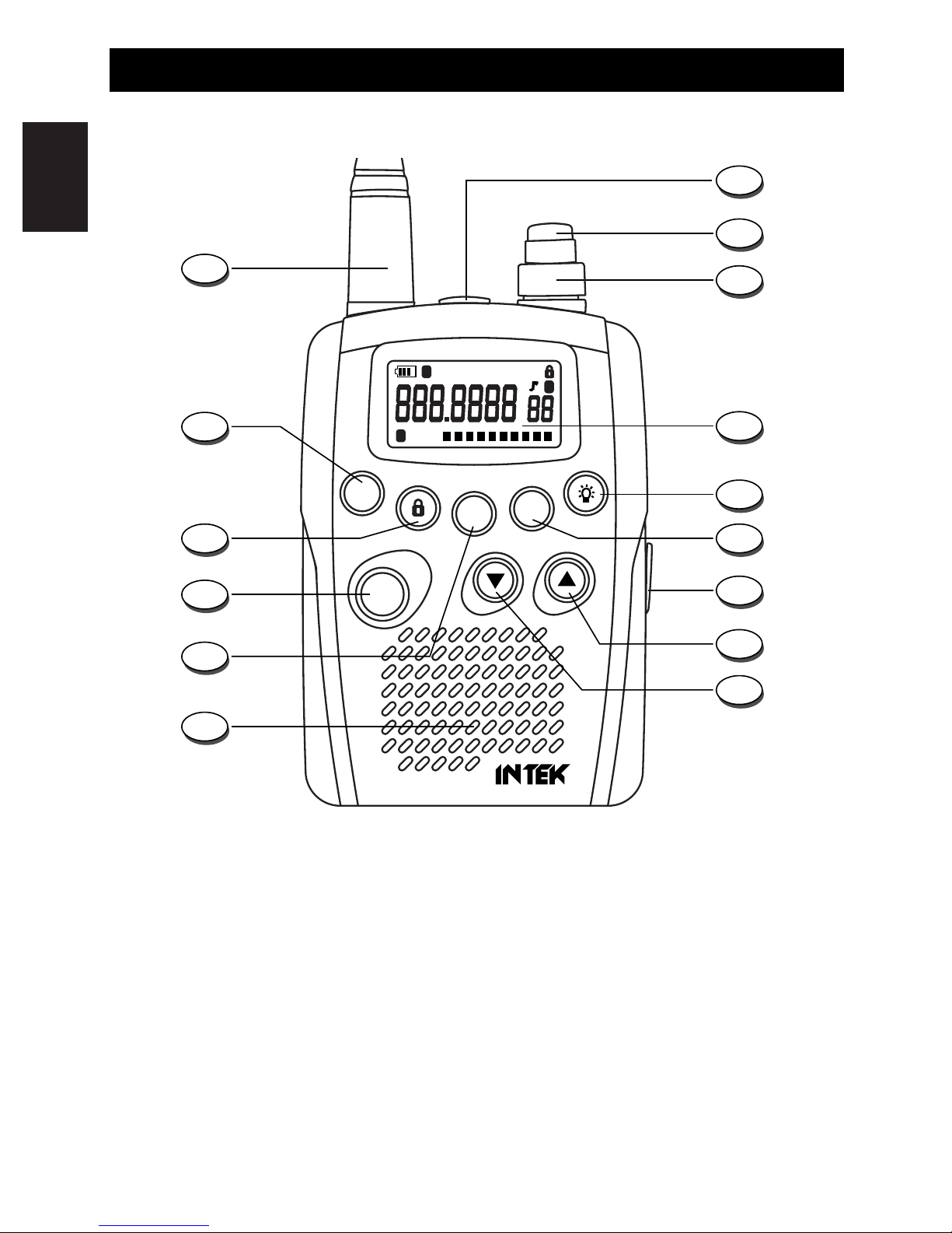
Front Panel
- 5 -
F
BEEP
DW
BND
STEP
SC
MW
MR
MO
AR-109
AIR BAND RECEIVER
S-RF
AIR NFM WFM DW SC
13579
F
B
M
1
4
5
6
10
9
8
7
3
2
13
12
11
14
15
English
1. Antenna
High efficency rubber SMA antenna.
2. Earset Jack
Connect an external earset to this jack. The dust cover prevents dirt and moisture from getting
inside the radio.
WARNING !
Use only original accessories. Connecting and using accessories other than the original
ones, may cause serious damage to the radio and will void the warranty.
Always set the volume to minimum before connecting an external earset, in order to avoid
damaging the earset or the user’s ear.
S-RF
AIR NFM WFM DW SC
13579
F
B
M
A
P
B C D E F G
H
M
I
L
O
N
Controls and Indicators
- 6 -
3. VOL/OFF (On-OFF/Volume) Control
This knob switches the radio ON and OFF and it adjusts the volume control to the desired level.
4. SQ (Squelch) Control
The SQL control allows to silent the receiver by cutting the background noise, when no signals
are received. Turn the knob clockwise until the background noise is cut. Turn the knob counter
clockwise (SQUELCH opening) in order to listen to the weakest signals.
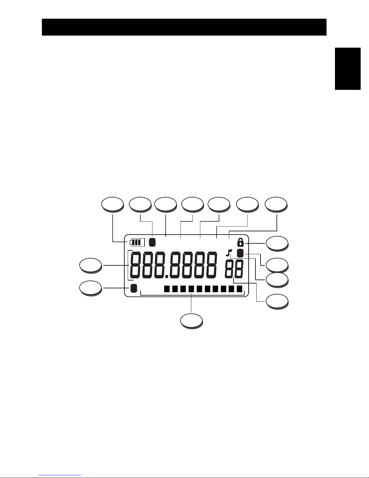
5. LCD Display
Large size LCD display with orange color backlight function for best readability in darkness. The
4-line LCD indicates simultaneously all the programmed settings and all the enabled functions.
Digital 10-bar Signal Meter and 4-bar battery level indicator.
LCD Display
A. Battery Level Indicator
It shows the current battery level condition and the charging process.
B. F Icon (Function Mode)
The F Icon (B) is lighted when the F key (13) is pressed.
C. AIR Icon
The AIR Icon (C) is lighted when the AIR band is selected.
D. NFM Icon
The NFM Icon (D) is lighted when the VHF NFM band is selected.
English

English
Controls and Indicators
- 7 -
E. WFM Icon
The WFM Icon (E) is lighted when the WFM Radio band is selected.
F. DW Icon
The DW icon is lighted when the DW (DUAL WATCH) function has been enabled.
G. SC Icon
The SC icon (G) is lighted when the SCAN function has been enabled.
H. KEYLOCK Icon
The KEYLOCK (H) icon is lighted when the keypad lock function has been enabled.
I. M Icon
This icon indicates the Memory Mode operation.
L. BEEP Function Icon
The Beep Icon (L) is lighted when the Beep function is enabled.
M. Memory Channel Number
It indicates the selected memory channel number, total 99 memory channels are available.
N. S-RF Digital Bar Meter
The 10-bar digital meter indicates the received signal strength.
O. B Icon
The B icon (O) is lighted when the radio is receiving a signal or when Squelch is open.
P. Frequency Readout
Full 7-digit frequency readout in KHz.
6. LIGHT / BEEP Key
LIGHT
Shortly press the LIGHT (6) key to backlight the LCD display. The LCD backlight will be turned
OFF automatically after 4 seconds or press the LIGHT key (6) again to turn OFF the LCD
backlight.
BEEP Function
This feature enable a short beep tone to confirm that the radio has been turned on. To enable
or disable this feature, press the F Key (13) and the Beep Key (6). When this feature is
disables, the keypad program tone and the error beep tone will not sound. When this feature is
enabled, the BEEP Icon (I) is lighted on the LCD display (5).

English
Controls and Indicators
- 8 -
7. MR (Memory Read) / MW (Memory Write) Key
This receiver contains a total of 99 memory locations for each Air band, VHF FM band and
WFM band where desired frequencies can be programmed by the user. Programming of the
desired frequencies can be carried our in the following ways for each band. Please refer to
MEMORY OPERATION at page 12.
8. Charge Jack
Connect the supplied 230VAC battery travel charger to this jack.
9. UP Key
The UP key (9) is used to change frequency, memory channel and toggle setting for the other
selected functions.
10. DOWN Key
The DOWN key (10) is used to change frequency, memory channel and toggle setting for the
other selected functions.
11. Built-in Speaker
Built-in front speaker.
12. MO / STEP Key
MONITOR FUNCTION
Quickly press the MO/STEP key (12) to activate the Monitor function. This function opens
Squelch in order to listen to the background noise and weak signals. When the Squelch is open,
the B Icon (O) is lighted on the LCD display.
FREQUENCY STEP SELECTION
You could preset the channel steps value for each band listed below :
Air Band channel steps: 12.5 KHz, 25 KHz and 8.3 KHz
VHF Band channel steps: 5 KHz, 10 KHz, 12.5 KHz, 15 KHz, 20 KHz, 25 KHz and 50 KHz.
WFM Band: No channel step. It is fixed at 100 KHz.
To select the desired frequency step, please proceed as follows :
Press the F (13) and MO/STEP key (12); the LCD display will show the CS indication and the
selected frequency step. Press the UP (9) or DOWN (10) keys to select the desired frequency
step then press MO key (12) to confirm. After preset, when you press the UP (9) or DOWN (10)
keys, the frequency will move up or down in the selected channel step value.

English
Controls and Indicators
- 9 -
13. F Key
Press this key to select the Function Mode. The F Icon (B) will appear on the LCD Display (5).
14. KEYLOCK / BND key
KEYLOCK
Press and hold this key for about 3 seconds to enable the keypad LOCK function; the LOCK Icon
(H) will appear on the LCD display (5). Press and hold this key again to disable the keypad LOCK
function.
BAND SELECTION
To select the desired band from Air band, VHF band and WFM band (in loop) press the F Key
(13) then press the LOCK/BND Key (14). The selected band name will appear on the LCD
display (Air bAnd, uHF bAnd, FM bAnd).
15. SC / DW Key
SCAN FUNCTION
Shortly press the SC/DW (15) key to start the frequency/memory channel scanning (refer to
AUTOMATIC SCANNING at pages 12 and 13).
DUAL WATCH FUNCTION
Press the F Key (13) and the SC/DW key (15) to enable the Dual Watch function. This function
allows to monitor 2 differents frequencies / memory channels (refer to DUAL WATCH
FUNCTION at page 14).
English
Controls and Indicators
- 10 -
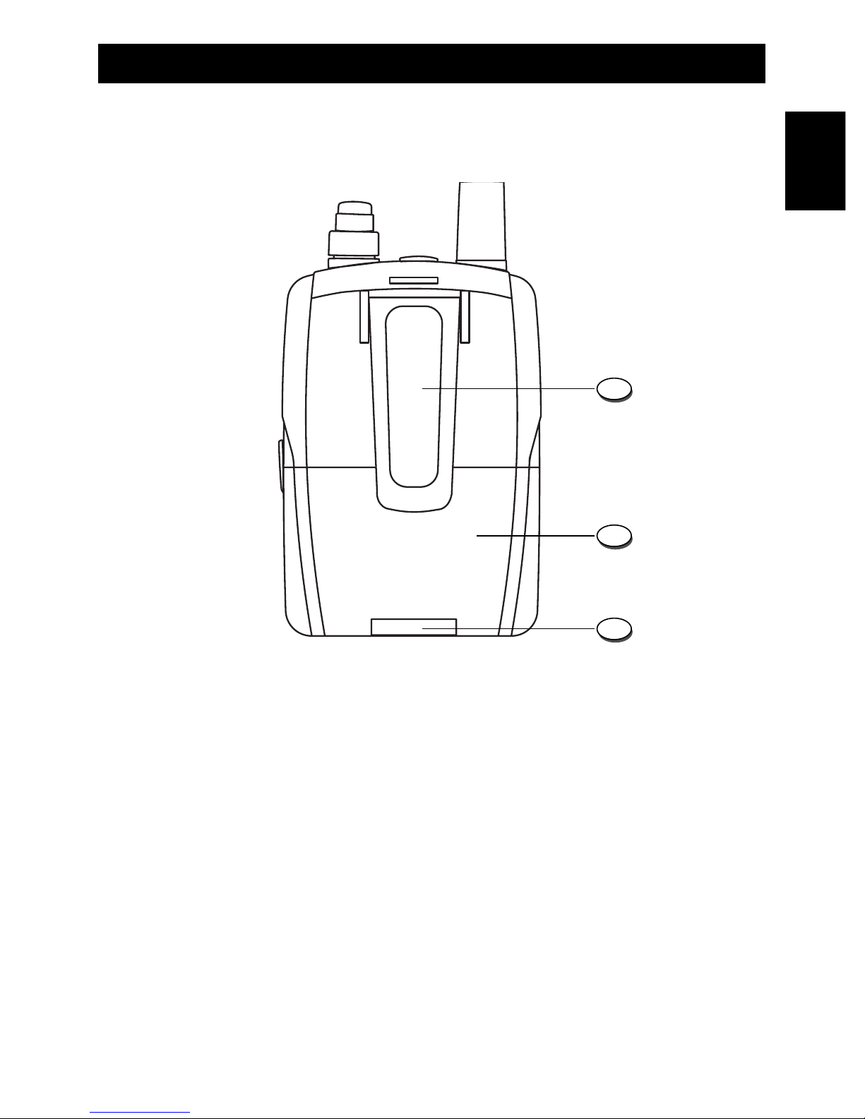
16
18
17
16. Belt Clip
1. To install the belt clip, slide it down into the special slot situated in the rear side of the
unit, until the block system make a click.
2. To remove the clip, pull the block tab toward exterior and slide the clip toward the up
side of the unit.
17. Battery Door
Open this cover (17) to install or remove batteries.
18. Battery Door Locker
This tab is used to lock or unlock the battery door.
Rear Panel

English
Operation
- 11 -
FREQUENCY SELECTION
Direct Selection
Press the UP (9) or DOWN (10) keys to select the desired frequency, according to the selected
frequency STEP (refer to the ITEM 12 at page 8).
Cursor Function
The desired frequency can be directly entered by using the Curson Function. This function
allows to select the 2nd, the 3rd, the 4th and the 5th digit of the used frequency.
To enter the frequency directly using cursor function, please proceed as follows :
1. Select the desired frequency (P) by using the UP (9) or DOWN (10) keys.
2. Press the F Key (13) and the UP Key (9) to move the cursor to the right or the F Key (13)
and the DOWN Key (10) to move the cursor to the left on the selected frequency. The
selected frequency digit will blink on the LCD Display (5).
3. Every time the F Key (13) and the UP (9) keys are pressed, the next digit on the right will
start to flash.
4. Every time the F Key (13) and the DOWN (10) keys are pressed, the previous digit on the
left will start to flash.
Example of frequency selection : 150.4650 MHz on the VHF Band.
1. Press the F Key (13) and the BND Key (14) until the VHF Band is indicated on the LCD
display.
2. Press the F Key (13) and the DOWN Key (10). The 5th digit of the frequency will start to
blink. Now press the UP (9) or DOWN (10) keys to set the value to “5”.
3. Press the F Key (13) and the DOWN Key (10). The 4th digit of the frequency will start to
blink. Now press the UP (9) or DOWN (10) keys to set the value to “6”.
4. Continue this process for the remaining digits until you have entered the desired frequency
(the first digit of the frequency will can not be changed).
5. Press the MO Key (12) to confirm the frequency selection.
The same procedure is followed for call and memory channels when selecting the desired
frequency.
 Loading...