

Page 1

WARRANTY
Intek, Inc. warrants each Rheotherm product to be free from defects
in material and workmanship under normal use and service, Intek's
obligation under this warranty being limited to making good any part
or parts thereof which shall, within one (1) year after delivery of such
product to the original purchaser, be returned to Intek with
transportation charges prepaid and which Intek's examination shall
disclose to its satisfaction to have been thus defective; this warranty
being expressly in lieu of all other warranties, express or implied and
all other obligation or liabilities on Intek's part. The purchaser will
assume all responsibility and expense for removal, decontamination
and reinstallation of equipment.
Rheotherm flow meters are manufactured under United States patent numbers 4,255,968; 4,942,763; 4,949,578; 5,485,754 and 5,752,411
Intek, Rheotherm, RheoVac, Rheovec, Rheomax and RheoSmart are registered trademarks of Intek, Inc.
Intek, Inc.
751 Intek Way
Westerville, Ohio 43082-9057
TEL: (614) 895-0301 • FAX: (614) 895-0319
website: www.intekflow.com
e-mail: sales@intekflow.com
Page 2

TABLE OF CONTENTS
SECTION 1 ! GENERAL INFORMATION ......................................... -1-
1.1 INTRODUCTION ..................................................... -1-
1.2 DESCRIPTION OF OPERATION ........................................ -2-
1.3 PRECAUTIONS ...................................................... -2-
SECTION 2 ! INSTALLATION................................................... -4-
2.1 TRANSDUCER ....................................................... -4-
2.2 TRANSMITTER ELECTRONICS ........................................ -6-
2.3 ELECTRICAL CONNECTIONS ......................................... -7-
SECTION 3 ! OPERATION..................................................... -13-
3.1 START UP.......................................................... -13-
3.2 GENERAL INFORMATION ........................................... -13-
3.3 OUTPUT SIGNALS .................................................. -13-
3.4 KEYPAD and DISPLAY............................................... -14-
3.5 OUTPUT CURVE .................................................... -16-
SECTION 4 ! MAINTENANCE ................................................. -17-
4.1 GENERAL MAINTENANCE........................................... -17-
4.2 FLOW CALIBRATION ADJUSTMENT .................................. -17-
4.3 SPARE PARTS ...................................................... -17-
4.4 TRANSDUCER & TRANSMITTER FUNCTIONAL TESTS . . . . . . . . . . . . . . . . . . -17-
4.5 TROUBLE SHOOTING ............................................... -20-
SECTION 5 ! CUSTOMER SERVICE ........................................... -23-
5.1 QUESTION ON EXISTING HARDWARE ................................ -23-
5.2 TROUBLE SHOOTING ............................................... -23-
5.3 FACTORY AND FIELD SERVICE ...................................... -23-
5.4 DECONTAMINATION OF EQUIPMENT ................................ -23-
5.5 QUESTIONS ON NEW EQUIPMENT.................................... -23-
SECTION 6 ! CUSTOM INFORMATION ........................................ -24-
6.1 UNIT IDENTIFICATION .............................................. -24-
6.2 CONFIGURATION ................................................... -24-
6.3 SPECIAL INSTRUCTIONS ............................................ -24-
TABLE OF ORIGINAL CALIBRATION DATA ................................ -25-
OUTPUT DEFINITION TABLE ............................................. -25-
APPENDIX Figure A-1 Flow Output Curve
©Intek, Inc. 2000
Manual no. A2009808 Rev. B
I:\OFFICE\WPMANUAL\Man200 rvb.wpd
Page 3

1.1 INTRODUCTION
SECTION 1 ! GENERAL INFORMATION
The Model 200 is a “smart” instrument having performance characteristics described in SECTIONS 3,
4, and 6. Rheotherm precision flow meters are designed to provide accurate linear or non-linear
®
(depending on the model) representation of fluid flow rate. They are manufactured exclusively by Intek,
Inc. and employ a patented thermal technique used by industry since 1978. The unique transducer
designs have protected sensors, are easy to install and require little or no maintenance.
Each Rheotherm flow meter consists of two elements — a transducer and a transmitter unit. The
transducers come in two basic designs, intrusive and nonintrusive (SECTION 2.1). Design selection is
based on application constraints or customer preference. The transmitter, for signal processing, is
housed in one of four basic enclosure styles (SECTION 2.2). Again, selection is based on application
requirement.
Key features of Rheotherm instruments are:
• Nonintrusive flow measurement — For pipe sizes from 0.030 to 2 inches, flow sensing can
be done from outside the flow tube.
• No moving parts — There are no rotating, translating, undulating or oscillating parts to wear,
stick, break or fatigue.
• Chemical compatibility — The wetted surface(s) can be any of a number of corrosion resistant
metals or alloys. There are no internal joints or seals in most TU type transducers.
• Flexibility — Rheotherm meters can be ordered calibrated for mass or volumetric units or in
average velocity. Flow rate, totalization and fluid temperature displays or output signals are
available, as well as rangeability up to 100:1 or more.
• Fluid pressure options to 10,000 psi (check transducer tag for rating on your unit).
• Withstands over ranging — No damage or change in calibration will occur due to excessive
flow rates many times higher than calibration range.
• Immunity to shock and vibration.
• Optional nuclear radiation hardening.
• Range of application includes measurements in capillary tubes to large diameter pipes or ducts.
I:\O FFIC E\W PM A N U A L\M an200 rvb.w pd
-1-
Page 4
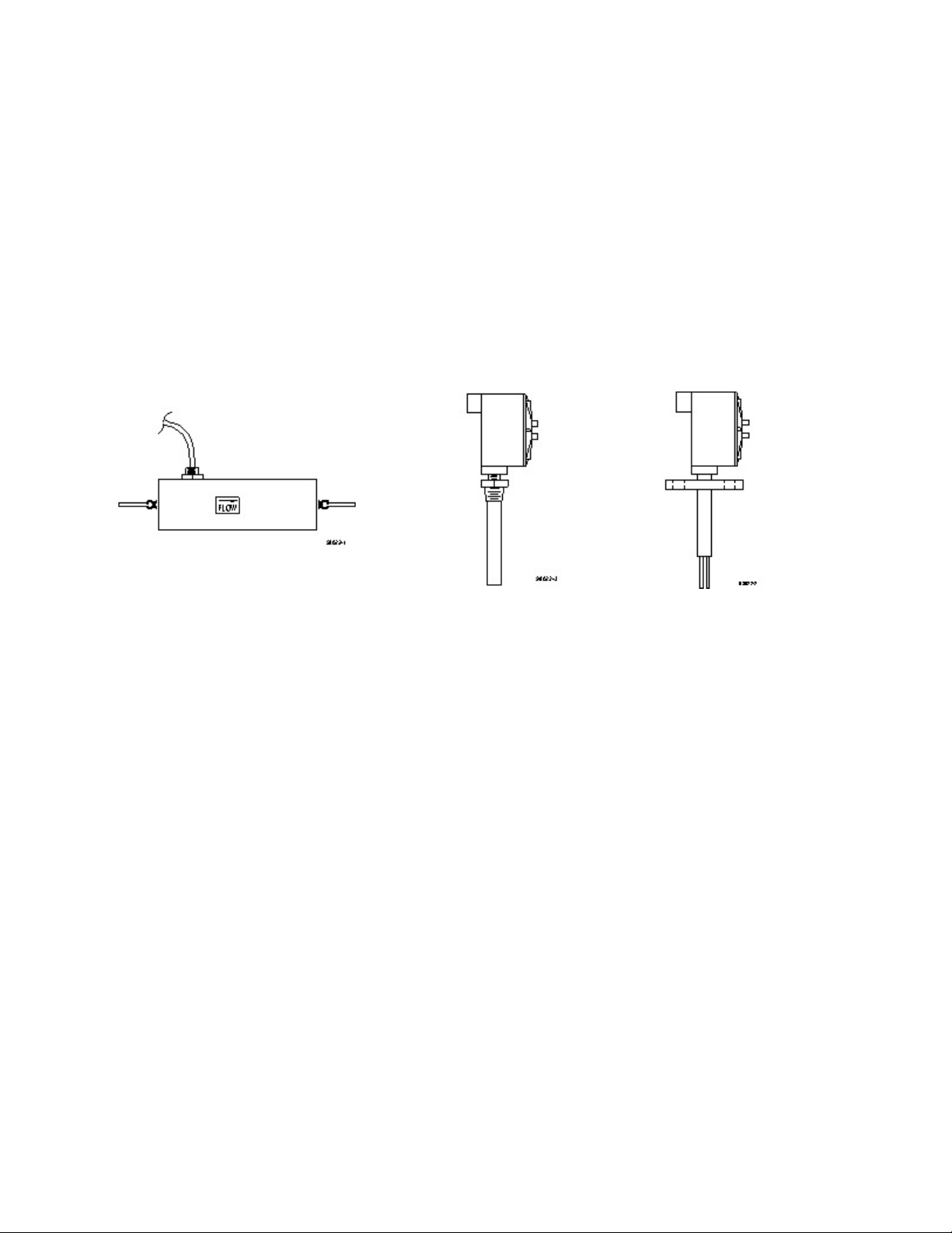
1.2 DESCRIPTION OF OPERATION
Rheotherm flow meters are available with various nonintrusive and intrusive transducer designs, but they
all use the same thermal sensing technique. Two temperature sensors are used — one is in thermal
equilibrium with the fluid and provides a fluid temperature reference, while the second temperature
sensor is located near a heater so that its temperature is slightly above that of the fluid. In a TU
transducer, the temperature sensors and heater are attached to the outside of the flow tube, whereas the
probe transducers have the sensors and heater located in the probe(s) that are inserted into the stream.
The rate at which heat is removed from the heated sensor by the stream is related to fluid velocity.
Hence, the measured temperature differential between the reference sensor and heated sensor is a
function of flow rate. Intek, Inc. is licensed to use this patented and trademarked flow measurement
method.
Nonintrusive transducer Example of Example of
(TU) single probe dual probe with
with NPT fitting flange fitting
1.3 PRECAUTIONS
!! CAUTION: Throughout the manual this caution notation indicates
that failure to execute the accompanying instructions
may cause the instrument or external equipment to
malfunction.
!! WARNING: A warning indicates that failure to execute the
accompanying instructions may cause permanent
damage to the instrument or external equipment.
1. Use proper input power — Check the label on the transmitter for the input power
requirements.
2. Use reasonable care in handling the transducer. Do not try to disassemble the transducers;
there are no removable parts.
TU — Excessive twisting or bending can damage the sensor. The flow tubes are thin-walled
tubing.
I:\O FFIC E\W PM A N U A L\M an200 rvb.w pd
-2-
Page 5

Probes (NPT/2I, NPT/I, BF/2I, BF/I, etc.) — Take care not to bend the probes or damage the
tips. Do not try to remove or turn the conduit junction box.
3. Check the transducer maximum temperature rating — Do not operate a transducer at or subject
it to a temperature above its specified limit.
4. Keep moisture out of the electronic enclosure and sensor junction box. Once cable
connections are made in the junction box, make sure the lid is tightly closed. Seal conduit
lines if they can become wet inside.
5. Keep transducer wetted surfaces clean and free of permanent layer build-up.
6. Do not exceed pressure limits of the tube or fittings.
7. Maintain a thermally stable environment (short-term) for the transducer and adjacent line
(See SECTION 2 — INSTALLATION).
These instructions cover installation, calibration and maintenance of Rheotherm meters in standard
configurations. Any special information pertaining to your unit is covered under CUSTOM
INFORMATION (SECTION 6). Time should be taken to carefully read these instructions prior to
installation of the equipment. Should any questions arise or problems occur, call Intek for immediate
assistance.
I:\O FFIC E\W PM A N U A L\M an200 rvb.w pd
-3-
Page 6

SECTION 2 ! INSTALLATION
2.1 TRANSDUCER
!! CAUTION: All transducers have a directional arrow on the tag and/or
etched into a metal part. Before installing a sensor, please note proper
flow direction. This is critical to sensor operation.
!! CAUTION: If you have more than one Rheotherm unit, make sure the
complete serial number of the transducer matches the complete serial
number of the transmitter. The transducer and transmitter are a matched
set. Components with different serial numbers should not be interchanged
unless specifically ordered as spares. The transducers have no user
serviceable parts, so do not try to disassemble, as permanent damage may
result.
The transducer style supplied with your meter is listed in the model code number in SECTION 6. Proper
installation of the sensor is necessary for achieving accuracy and repeatability. Installation suggestions
for each type of standard transducer are given here. For custom transducer installations, refer to
CUSTOM INFORMATION — SECTION 6.
Be sure wetted surfaces are clean before installing. If cleaning is needed, use non-residue solvent and
wipe dry. If the sensor has a junction box, keep moisture out. Make sure the lid is tightly sealed and,
if supplied, the gasket is in place. Seal conduit lines at the junction box if conduit lines can become wet.
1. TU (nonintrusive) — TU '16 and TUc transducers particularly require special care in handling
1
and installing to avoid damage to sensor tube stubs.
!! WARNING: TU transducers are made with thin-walled tubing — use
care when installing.
All TU transducers (other than '16 & c inch) should have straight line input and output
1
sections, typically 20 pipe diameters on the inlet and 6 to 10 diameters on the outlet. If
installed vertically, the flow should be flowing up through the sensor. Connection in the line
is via compression fittings, hose with clamp, threaded fittings or flanges, whichever is
appropriate. Care must be taken not to transmit a twisting force through the transducer's
midsection. The TU transducer, whether flanged or not, must not be used to pull other piping
together or to make up angular mismatch of fittings. The transducer junction box (if supplied)
should never be rotated for any reason.
1
TU '16 transducers may be sleeved with a c" tube for added support. Connection should
always be made to the '16" tube, as there is no assured seal between the '16" tube and the
11
sleeve.
I:\O FFIC E\W PM A N U A L\M an200 rvb.w pd
-4-
Page 7

Some TU transducers have an integrally mounted cable; do not pull on this cable, or attempt
to remove the fitting where the cable enters the sensor shell.
Fluid temperatures other than ambient require special attention. Thermal gradients from one
end of the transducer to the other, as well as along the radius of the connection pipe, are
undesirable. Therefore, effective insulation should be installed around the inlet and outlet
straight line runs. Gradients which may exist in the line further up stream can be removed if
an insulated elbow is installed in the line prior to entering the straight line portion of the
plumbing. Metallic support braces for the sensor or adjoining plumbing can act as a heat sink
and cause operational problems in high temperature applications. The support braces should
be thermally isolated from the line to avoid large heat conduction effects.
If the transducer is for use above 212°F, it will have a side arm and connector box, where the
internal high temperature wiring is connected to the lower temperature transducer cable. Free
air should be allowed to flow around the side arm and connector box to keep the box cool.
The side arm can be insulated up to one third of its length from the transducer body.
In these applications, proper thermal control is vital to accurate meter performance. Nonuniform heat tracing, relay on/off temperature controllers and oscillating proportional type
control should always be avoided. Steam trace lines with good pressure regulation or properly
tuned proportional temperature control systems are effective in maintaining uniform fluid
temperature. A box around the sensor and inlet tubing is highly recommend for operating
temperatures higher than room ambient. Allow enough inlet tubing inside the box to allow
the fluid temperature to become the same temperature as the surrounding air. Separately
control the box air temperature at the same temperature as the incoming fluid temperature
to minimize thermally induced indication errors.
Flow stream conditioning must also be considered to maximize meter performance. Avoid
upstream protrusions and short distance straight runs. Flow pulsations, such as those created
by metering pumps, may cause the instrument to differ from the factory calibration.
Furthermore, if the flow is varied by stroke and by pump speed adjustment, the indication will
most likely be non-repeatable. If you are using a pump of this type, it is recommended that
a pulsation dampening device be used to provide smooth continuous flow. A second choice
would require readjustment of the instrument calibration after installation (See SECTION
4.2).
For liquid measurement systems using high pressure gas to force flow, the effects of the
absorbed gas must be considered. In these cases, sudden pressure drops up stream of the
sensor such as line size expansions, control valves, and pressure dropping regulators must be
avoided. Sudden pressure drops can cause the absorbed gas to release into the liquid, making
the flow sporadic and difficult to measure. Control valves should be placed down stream of
the sensor.
The ideal installation will provide the sensor with well established smooth flow, uniform
system temperature and consistent fluid media.
I:\O FFIC E\W PM A N U A L\M an200 rvb.w pd
-5-
Page 8

2. Intrusive Probes —
!! IMPORTANT: Recommended straight run for best accuracy is a
minimum 20 diameters up stream and 10 diameters down stream.
The various probe transducers are mounted through a threaded collar (NPT/2I and NPT/I) or
flanged tee (BF/2I or BF/I). Other fittings and sensor designs are also available and are
discussed on the Custom Information page. Generally the probes are sized so the tips extend
½ to 1 inch beyond the pipe center line when properly installed. There are exceptions to this
in certain applications; see CUSTOM INFORMATION (SECTION 6) as it applies.
Proper alignment of the sensor with flow is important; the flow direction is indicated on the
transducer tag and/or etched into the transducer. All dual probe transducers (NPT/2I, BF/2I)
are installed so that the two probes are side-by-side across the fluid stream. Never rotate the
junction box that houses the terminal cable connection. If this occurs the transducer could be
damaged and/or installed misaligned with the flow direction.
For high temperature applications, the sensor and surrounding line should be well insulated.
Leave a portion of the transducer neck un-insulated to allow heat dissipation before reaching
the junction box.
2.2 TRANSMITTER ELECTRONICS
Various types of transmitter housings are available. These include NEMA 4, laboratory bench type,
explosion proof, and panel mount enclosures as well as special models to meet customer requirements.
These come in different sizes to accommodate options and special features.
1. NEMA 4 — The standard industrial housing, this enclosure is watertight (non-submersible)
when the door is properly clamped shut. The housing should be mounted such that wire/cable
ports are located at the bottom of the housing, to reduce problems associated with water spray,
condensation and settling of dust and dirt. An all stainless steel version (NEMA 4X) for
corrosive environments is also available.
2. NEMA 7 — For use in hazardous (class I) environments. The lid should be closed and all
bolts tightened before the unit is powered up. If a NEMA 7/NEMA 4 enclosure was ordered,
the unit will have a rubber gasket in a groove in the top of the enclosure base. Conduit seals
are frequently required, so applicable code requirements should be met when installing the
conduit into the box.
3. Laboratory — This table-top unit is NEMA 1 only; do not spill liquid on it or use in a wet
environment. This unit typically has a grounded power cord, and all transducer and output
connections are located on the back of the enclosure.
4. Panel Mount — For use in a control panel, mounted so the enclosure face is flush with the
panel surface. Most or all connections are made on the back of the enclosure. This unit is
NEMA 1 only; do not use in a wet environment.
I:\O FFIC E\W PM A N U A L\M an200 rvb.w pd
-6-
Page 9

The transmitter housing should be installed keeping in mind the length and routing of the transducer
cable. Standard cable length is six feet but it can be specified up to 200 feet. If, after calibration of the
unit, the cable length is changed (a portion cut off or additional cable spliced on), there may be a shift
in the calibration due to the change in cable resistance. The size of this effect depends on the amount
of change. If a noticeable shift occurs, it may be necessary to adjust the output as described in the
calibration instructions in SECTION 4.2.
Unless otherwise specified, normal ambient environment for the transmitter is 0-120°F. Recommended
maximum temperature is 135°F.
2.3 ELECTRICAL CONNECTIONS
1. Verify/configure the input power. The input power requirement is listed on the tag on the
transmitter enclosure. Be sure the input power source to be used is properly selected in the
unit. Input power can be either 115 Vac or 230 Vac single phase, 50-60 Hz. The power
configuration may be changed in the field. Using Figure 1, locate the power select switch on
the lower printed wiring board and slide the power select switch to either the 115V or the
230V position. Do not apply power to the instrument until all other connections and
optional selections have been made.
!! CAUTION: The following output signals, both ! and +, are isolated
from the transducer and power ground. However, the outputs are not
isolated from each other. All of the 4 to 20 mA receiver channels must
have independently isolated inputs. Again, the 4-20 mA, RS232/422, and
status outputs are all common to each other.
I:\O FFIC E\W PM A N U A L\M an200 rvb.w pd
Figure 1 - Transmitter Hardware Configuration
-7-
Page 10

2. Check the analog output configuration of the transmitter and your input device. The analog
output terminals for flow and probe temperature are shown in Figure 2 at the far left terminals
of JP7. If the instrument is configured for current outputs, set the flow and temperature output
type for either passive or active transmitter by positioning the header pin shunts shown in Figure
1 at JP12 and JP13. (Active: Current to loop is sourced by transmitter. Passive: Output receiver
sources current.) This figure shows an active configuration for the flow output and a passive
configuration for the temperature output. Typically, units are shipped configured in the active
mode, unless the voltage output option is specified.
Figure 2 - Transmitter Terminal Connections
3. The next JP7 output is a 2KHz full scale pulse output. The standard configuration is a 0-15Vdc
pulse that is proportional to flow with a 50% duty cycle. Unless otherwise specified, the minimum
pulse duration is 250 :s .
The two possible configurations are:
a. Voltage pulse (standard) — This option uses the same circuit and connections as the open
collector. A 1kS pull-up resistor is added and tied to a +15V voltage source. This provides
the 0-15 Vdc pulse.
b. Open collector (optional) — The (+) connection on the output terminal is the collector of a
2N2222A NPN transistor. The (!) connection is the emitter of the same transistor. The pulse
rate is linear with flow. Recommended maximum current is 150 mA; maximum open circuit
voltage is +36Vdc.
. WARNING: Do not reverse the terminal polarity when connecting to an
external supply.
4. Outputs ‘OUT1’ and ‘OUT2’ are 0-15Vdc digital outputs factory default set as low flow and
high temperature indicators respectively. OUT1 is factory set to alarm at flows below the
lowest calibrated flow. OUT2 is set to alarm at temperatures above the rated maximum
temperatures. The alarm state of these outputs is 0Vdc, which also occurs when power to the
instrument is lost.
I:\O FFIC E\W PM A N U A L\M an200 rvb.w pd
-8-
Page 11

5. The status output, also located on field wiring terminal, JP7, is a digital 0-15Vdc output. This
output will go low in the event of a fault or power loss. If a non-standard option has been
ordered there will be additional notes in the SECTION 6.3 — SPECIAL INSTRUCTIONS.
6. The reset input terminals are provided for remote reset of the totalizer. To reset the totalizer
these two terminals need to be shorted together. The ‘+’ terminal is connected to an internal
+5Vdc supply ‘+’ and the ‘-’ terminal is connected to an internal input device and to output
ground through a 47kS resistor. If an open collector (NPN) is used to make this connection,
wire the collector to the ‘+’ terminal and the ‘-’ to the emitter. Reverse the polarity if a PNP
type open collector transistor is used. Connections to this input must be isolated. A
grounded (connected to instrument output ground) emitter of the open collector may destroy
the open collector transistor.
7. Choose a path for the transducer to transmitter cable conduit. Route the transducer interface
cable conduit. Do not cut or splice the cable, as this may affect the instrument calibration.
Pull the cable through the conduit starting at either end; coil up the remaining length outside
the transmitter or transducer enclosure, or in a cable junction box.
8. Pull wires through the conduit. Wire for power connection must be at least 24 gauge or as
required by applicable local or company wiring codes. After pulling the wire, pot the conduit
or wires near the enclosure if there is any possibility of water from condensation or spray
entering the enclosure through the conduit.
!! WARNING: The transmitter unit is not protected against condensed
liquid water inside the enclosure. Be sure conduit interfaces are dry or
sealed at the instrument to prevent condensation that may be present in
conduit lines from entering the enclosure.
9. Make wiring connections. Power should be off at this time. Refer to Figure 3 for system
wiring detail.
!! !! WARNING: Verify the wiring. The equipment can be permanently
damaged if not wired as instructed in this manual.
10. Close the lid of the enclosure. Make sure it is tight enough to make a good seal against
the gasket and ensure all other enclosure openings are completely watertight.
I:\O FFIC E\W PM A N U A L\M an200 rvb.w pd
-9-
Page 12

Figure 3 . S ystem W iring D etail
I:\O FFIC E\W PM A N U A L\M an200 rvb.w pd
-10-
Page 13

2.4 SERIAL OUTPUT
The Model 200 has RS232/422 output receptacles used during factory calibration. There is a data stream
that can be accessed with a specially wired six-position RJ-11 jack (modular telephone jack) and
computer connection. See Table 1 and Figure 4 for wiring information.
If a distance of greater than twenty-five feet is needed for the serial communications, RS-422 should be
used instead of RS-232. Inspect the jumper at JP14 (Figure 2) for the proper communication type.
TABLE I. RJ-11 to DB-9 Module Adapter
RS-232 CONFIGURATION RS-422 CONFIGURATION
RJ-11 Pin Out DB-9 Pin Out RJ-11 Pin Out DB-9 Pin Out
Tx (transmit) 1 N/C 1 Tx+ (transmit+) 1 Rx! (receive!)
1
2 N/C 2 Tx (transmit) 2 Tx! (transmit!) 2 Rx+ (receive+)
3 Rx (receive) 3 Rx (receive) 3 Rx+ (receive+) 3 Tx+ (transmit+)
4 N/C 4 N/C 4 Rx! (receive!) 4 N/C
5 Power (+5V) 5 Ground 5 Power (+5V) 5 Ground
6 Ground 6 Pulled high 6 Ground 6 Tx! (transmit!)
7 N/C 7 TBD
8 Pulled high 8 TBD
9 N/C 9 TBD
Custom software may be developed by the user to receive and archive Model 200 data into a computer
system. The electronics has a serial data protocol of 9600 baud, no parity check, eight data bits and one
stop bit (i.e., 9600,N,8,1). Each transmitted group of data is sent in a standard ASCII coded format
representing each process variable value, instrument identification and status information.
The data stream consists of six fields, followed by a carriage return <RETURN>. The first three fields
are the process values. Following the process variables are the Model 200 serial number (ten bytes), the
process identification tag number (ten bytes), and the system status (seven bytes). The data stream is
then ended by a single <RETURN> byte (ASCII code 13). The total number of bytes transmitted in each
data stream is 50 bytes including the trailing <RETURN>. This data group is sent about once every
second. The field names and number of bytes in one data stream are shown below.
Flow Rate
(%)
6 Bytes 10 Bytes 6 Bytes 10 10 7 1
Totalizer
(Field Units)
Temp.
(°F)
Instrument
S/N ID Tag No. Status Term. (CR)
The first and third process variables, % of full scale flow rate and temperature, are sent in the fixed
decimal format of xxx.xx with leading and trailing zeros inserted to maintain the six byte character
length. The second process variable sent is total flow, with a ten byte character length and leading and
trailing zeros, as well as a fixed decimal point (if used), inserted. The next three fields are ASCII text
strings followed by the <RETURN>. Example: The six bytes for a temperature of 75.5°F would be
075.50, or 48,55,53,46,53,48 ASCII.
I:\O FFIC E\W PM A N U A L\M an200 rvb.w pd
-11-
Page 14

Figure 4 - Serial Communications Interface
I:\O FFIC E\W PM A N U A L\M an200 rvb.w pd
-12-
Page 15

SECTION 3 ! OPERATION
3.1 START UP
Typically, the instruments come from the factory set up for the flow range of interest to the customer.
Following installation all that is required is to switch on power and initiate flow in the measurable flow
rate range. Flow sensors that are not calibrated directly on the fluid to be measured are so indicated in
this manual (SECTION 6) and require an in-line field calibration.
When power is first turned on, the output reading or signal will indicate full scale. The alpha numeric
display will have the message of ‘*INTEK, INC.*’ on the top line and ‘(614)895-0301’ on the bottom.
After a few seconds the message will change to ‘s/n xxxxx-xx Cal x’ / ‘Software Ver: xxxxxx’. Again
after a few seconds the top display line will change to ‘initializing.’ The status output will be low (alarm
condition) and the flow output will be 100%. The flow value will be internally software monitored for
stability or a factory set time-out (10 sec. default) will occur before the display is set to the normal state
(Flow / Temperature will be the factory default). After ten to forty-five seconds (depending on flow
meter response) the reading will stabilize. The instrument time constant is generally between 4 to 12
seconds. Higher average flow rates will result in an observed faster response time for a given unit.
3.2 GENERAL INFORMATION
The Rheotherm instrument is compensated for a wide range of both ambient and flowing media
temperatures. However, abrupt changes in the temperature of the flowing material can cause the
instrument output to deviate from the true representation of flow rate. An accurate reading is obtained
only when the transducer is in thermal equilibrium with the material. Typically, a 20°F abrupt change
in temperature may require 40 seconds to stabilize. To maintain optimum accuracy temperature ramps
should be kept below 1°C/minute.
Rheotherm instruments are calibrated for a particular fluid, either at the factory or in the field. If the
fluid changes properties, the calibration changes. Therefore, once calibrated, do not allow fluid
properties such as density and viscosity to change (other than the intrinsic changes which occur with
temperature variation). If the fluid is changed, a recalibration may be attempted following the procedure
in SECTION 3.4.3. If this procedure does not provide a good calibration for the range of interest on
the new fluid, contact the factory.
3.3 OUTPUT SIGNALS
Standard features for all Model 200 instruments include one 2 x 20 alpha numeric LED backlit display,
two 4-20 mA or 0-10Vdc analog outputs, one 0-15Vdc digital pulse flow output, two 0-15Vdc digital
flow/temperature alarm outputs, one 0-15V digital status port, and one serial communication port. Both
flow and temperature process variables are linear, temperature compensated values. Each output signal
is scaled such that 4 mA (0Vdc for voltage output) represents 0% of the rated full scale value and 20 mA
(10Vdc) represents 100% of the rated full scale value. The factory set full scale values and definitions
of process variables are listed in Table II.
I:\O FFIC E\W PM A N U A L\M an200 rvb.w pd
-13-
Page 16

1. Analog Outputs — The unit will have two 0-5Vdc, 0-10Vdc or 4-20 mA signals for flow and
temperature outputs. The default configuration for each output is 4-20 mA active transmitter.
See SECTION 2.3.3 for a discussion of the output types. The ‘FLOW’ output covers zero to
100% of full scale flow and quickly drops to zero below the instrument’s calibrated low flow
value. Refer to the Output Curve (Figure A-1) at the end of the manual. Similarly, the
‘TEMP’ output covers zero to 100% of the specified temperature range. Note that the zero
output value is not necessarily 0°F or 0°C (see Output Definition, SECTION 6).
2. Pulse Output — The factory standard for pulse frequency is 2 KHz at full scale flow as a flow
rate or totalization signal. Specific units of volume or mass per pulse may also be supplied
to drive a customer supplied totalizer. Refer to Output Definition, SECTION 6.
3. Digital Alarm Outputs — The two outputs labeled ‘OUT1’ and ‘OUT2’ can be used for
monitoring critical process conditions and for alarming exceeded process limits. They are
factory default set for low flow and high temperature alarms respectively. Refer to Output
Definition, SECTION 6 for specific alarm values or custom configuration information
regarding these outputs.
The Status alarm output indicates a processor busy, instrument or sensor fault, or a loss of instrument
power. When this output is low, the instrument is not capable of indicating flow or temperature properly
and may produce unexpected outputs. This output will normally go low when initializing or when
special diagnostic commands are specifically sent to the instrument. Otherwise, when the status output
is low observe the display for additional information and refer to the Trouble Shooting Section of this
manual.
3.4 KEYPAD and DISPLAY
The keypad can be used to change the information on the alphanumeric display as well as to adjust the
calibration.
Figure 5 - Keypad
!! !! CAUTION: Do not use the keypad while the serial communication port
is actively receiving data or commands from an external source. Temporarily
I:\O FFIC E\W PM A N U A L\M an200 rvb.w pd
-14-
Page 17

unplug the RJ-11 serial communication cable to avoid possible signal
contention while using the keypad.
1. CHANGING THE DISPLAY VARIABLES
Each display line can be independently set for flow, temperature, totalizer, time, date, serial
number/calibration/software version or last factory or field calibration adjustment. Use the TOP
or BOTTOM LINE SCROLL keys (see Figure 5) to select the desired display variable.
Flow = Four or five digit indication of flow in the specified calibration units.
Temp = A four digit (0.01 degree resolution) indication of temperature in degrees C.
Temp = A four digit (0.01 degree resolution) indication of temperature in degrees F.
Tot = A nine digit totalizer count is available on either the top or bottom line of the
alphanumeric display. Totalizer reset can be performed as described in
SECTION 3.4.2.
Time Used for internal archiving and event recording.
Date Used for internal archiving and event recording.
S/N, Cal The serial number of the transmitter with the selected calibration. There are
four possible calibrations A, B, C or D, which can correspond to different
fluids, sensors, or process configurations. See the Special Instructions Section
if a multi-calibration option is ordered.
Software Ver: Installed version of instrument software. Factory may require this number
when providing assistance.
Last Cal: Date of the last calibration or field adjustment performed on the instrument.
2. RESETTING THE TOTALIZER
There are two ways to reset the totalizer:
A. Using the keypad, set either the top or bottom line display to ‘Tot = ...’. Then simultaneously
press and hold the TOP LINE SCROLL and the BOTTOM LINE SCROLL buttons until the
totalizer value zeros.
B. The totalizer can also be reset remotely by closing contacts across the remote reset
terminals. See SECTION 2.3.7 for reset terminal instructions.
3. FLOW CALIBRATION ADJUSTMENT
SmartSpan is a feature that allows a two point calibration to be easily performed using the
keypad. Any two flow values can be accurately and independently set using the FLOW
CALIBRATION ‘Adj Lo’ or ‘Adj Hi’ buttons. Using a unique Intek algorithm, adjusting
either flow point will not interact or interfere with the previous adjustment in any way.
Establish flow at a known flow value near the low range of normal use (e.g., 15-20% of full
scale flow). Press either the ‘Adj Lo 8’ or ‘Adj Lo 9’ button to increase or decrease the flow
indication respectively. As you continue to hold the button the sensitivity will continue to
increase. For fine adjustment, release the button and continue to press and release to change
the offset incrementally. Recheck the measured flow, compare with the instrument indication,
and readjust as needed. Use the ‘Adj Hi 8’ or ‘Adj Hi 9’ buttons similarly at a high flow (e.g.,
85-95% of full scale flow) to complete the two point calibration.
I:\O FFIC E\W PM A N U A L\M an200 rvb.w pd
-15-
Page 18

A message of ‘Flow Not Valid’ during calibration means either there is no flow, or flow is out
of the measurable range of the unit.
!! !! CAUTION: Although the calibration adjustments can be made at any
flow value it is recommended that the low and high flows be at least 10%
apart from each other. If the desired accuracy is not met with this
technique, a factory assisted recalibration may be required.
A separate feature of the SmartSpan is the ability to disable and re-enable the calibration adjustment
function. This is done by setting both the top and bottom display lines to the ‘DATE’ field, then
simultaneously pressing the TOP LINE SCROLL and BOTTOM LINE SCROLL buttons. The
message ‘Flow Calibration Disabled’ will be displayed when disabling, and ‘Flow Calibration
Enabled’ when re-enabling.
Restoring the factory calibration settings can be accomplished by setting both the top and bottom
display lines to the ‘Software Version’ field, then simultaneously pressing the TOP LINE SCROLL
and BOTTOM LINE SCROLL buttons. The message ‘Factory Calibration Restored’ will be
displayed when this is performed.
4. SELECTING DIFFERENT CALIBRATIONS
Use this feature to select one of four (A, B, C, or D) different calibrations. This can be done by
setting both the top and bottom display lines to the ‘S/N, Cal Selection,’ then simultaneously
pressing the TOP LINE SCROLL and the BOTTOM LINE SCROLL buttons. Each time the two
keys are pressed simultaneously the cal field will advance to the next calibration (A, B, C or D).
Check your model number and if it contains a “-SW-” suffix, you have ordered a special multicalibration option. This means that two or more calibrations have been custom configured at the
factory. In this case refer to the Special Instructions Section for more information.
In general, a unit with a single calibration (which is the standard), will be shipped from the factory
with the B, C and D calibrations as duplicates of the original ‘A’ calibration. This allows you to
custom calibrate up to three additional different calibration settings while preserving the original
factory calibration.
3.5 OUTPUT CURVE
Figure A-1 is the final linearized flow output curve for your unit. The instrument has been calibrated
over the actual flow rate range indicated on the ordinate (Y axis).
I:\O FFIC E\W PM A N U A L\M an200 rvb.w pd
-16-
Page 19

SECTION 4 ! MAINTENANCE
4.1 GENERAL MAINTENANCE
Certain precautions should be taken to insure proper performance of all models of flow instruments.
Since the measurement technique involves a signal resulting from heat transfer to the flowing medium,
care should be exercised to prevent build-up of varying layers on the walls of the transducer. Layers
such as bacterial growth, dried paints, gas bubbles and non-solubles can result in measurement below
actual flow rates. Periodic checks and cleaning should be performed to insure a clean pipe or probe
surface.
It should be part of normal maintenance procedure to check the system for proper functioning.
Experience and other observable conditions should be utilized to determine the frequency of inspection.
Long term drift in the unit calibrations is not expected, but if a recalibration is required, refer to
SECTION 3.4.3. To test the flow switch action, the flow rate should be reduced below (for low flow
switch) or raised above (for high flow switch) the switching level. Then check and insure relay action
and continuity of the shut down or warning circuits which it operates.
The joints of all intrusive probes tips should be inspected for wear and corrosion.
4.2 FLOW CALIBRATION ADJUSTMENT
Occasionally over time or due to process condition changes a slight realignment of the calibration may
be required to maintain the desired indication accuracy. Periodically verify the instrument calibration
by comparing the indication versus another accurate flow measurement or against a trusted primary
standard. After characterizing the drift tendencies and considering the accuracy requirements, determine
a regular calibration verification cycle. Otherwise, an annual verification is recommended for typical
installations. Calibration instructions are located in SECTION 3.4.3 of the operation manual.
4.3 SPARE PARTS
The transducer and transmitter electronics are calibrated as a set, and cannot be randomly interchanged
with others. For critical applications, a complete spare flow meter (transducer and electronics) should be
stocked. A spare transducer can be stocked, if it is ordered and calibrated at the same time as the flow
meter. A spare electronics unit can be ordered anytime; this requires that special software also be
purchased in order to upload transducer specific calibration parameters. Contact the factory for more
information.
There are also two fuses which can be stocked: Wickmann part numbers 3740250041 (F2) and
3740160041 (F1) respectively, or equivalent.
4.4 TRANSDUCER & TRANSMITTER FUNCTIONAL TESTS
A test of the Rheotherm instrument functional operation can be performed in three phases:
1. Transducer continuity check.
2. Transducer isolation check.
3. Electronic circuit board check.
I:\O FFIC E\W PM A N U A L\M an200 rvb.w pd
-17-
Page 20

1. The transducer continuity check is performed as follows (see Figure 6-A):
A. Disconnect the transducer cable from the transmitter.
B. Make resistance measurements between the cable pairs as shown in Figure 6-A. The
readings should be as indicated; if not, consult factory for repair.
2. The transducer isolation check is performed as follows (see Figure 6-B):
A. Disconnect the transducer cable from the transmitter.
B. Make the circuit connections illustrated in Figure 6-B.
C. Probe all the conductors and note the voltage with respect to the instrument flow tube or
probe shaft. All readings should be less than 0.5 Vdc.
3. The sensor input to flow output of the electrical circuit is checked as follows (see Figure 6-C):
A. Construct the dummy transducer as illustrated in Figure 6-C. Select R2* and R3* for
approximate ‘TEMP’ value.
B. Turn off power to the unit.
C. Disconnect the transducer cable from the instrument.
D. Connect the dummy transducer to the instrument input.
E. Restore power.
F. Set both the top and bottom display lines to the ‘TIME’ field and simultaneously press
the TOP LINE SCROLL and BOTTOM LINE SCROLL buttons. ‘TEMP’ and ‘)T’ fields
should appear on the top and bottom display lines.
G. Adjust R1* (fine) for ‘)T’ value.
H. Compare the measured flow rate and the indicated flow rate to original calibration data
SECTION 6. Recheck ‘TEMP’ and ‘)T’.
*resistors of transducer simulator
I:\O FFIC E\W PM A N U A L\M an200 rvb.w pd
-18-
Page 21

Figure 6 - Transducer / Electronics Test Configuration
I:\O FFIC E\W PM A N U A L\M an200 rvb.w pd
-19-
Page 22

4.5 TROUBLE SHOOTING
The following tables provide easy-to-follow instructions to trouble shoot flow indication problems and
interpret instrument fault codes. The last table asks for data required by the factory in order to assist you.
Be sure to use a high input impedance digital voltmeter for the readings identified in Table IV. All
readings are to be taken from terminals BRN through R on JP2 (Figure 2). Complete Table IV and fax
it to the factory, (614) 895-0319.
TABLE II. Trouble Shooting Guide - Flow indication problems
OBSERVATION PROBABLE CAUSE REMEDY
Flow indication continually
drifting downward with
constant flow.
Flow indication saturates high
or low — will not respond to
flow change.
Flow indication varies with
flow but not stable.
1. Coating forming on wetted
surface of transducer.
1. Flow rate not within range of
meter.
2. Calibration out of range of
actual flow.
3. Partially failed component in
transducer or transmitter.
1. Fluid temperature not stable.
2. Fluid mixture not properly
blended.
3. Gas mixed with liquid.
4. Flow not fully developed.
1. Clean transducer periodically
or adjust calibration (Section
3.4.3) until layer build-up
stabilizes.
1. Check flow range requirements.
2. Refer to SECTION 3.4.3 for
Flow Calibration Adjustment.
3. Perform transducer and
transmitter functional test (see
SECTION 4.4). Write results
down and consult factory.
4. Replace fuse as needed.
1. Tune temperature controller,
add insulation and/or add static
mixer in front of transducer.
Monitor temperature indication.
Refer to Installation Section for
discussion on thermal
stabilizing flow system.
2. Add static mixer in front of
transducer.
3. Reduce gas pressure or check
for air ingress on suction side
of pump. Refer to Installation
Section.
4. Check inlet and outlet for
proper straight line length &
freedom from obstructions.
I:\O FFIC E\W PM A N U A L\M an200 rvb.w pd
-20-
Page 23

TABLE III. Trouble Shooting Guide - Instrument diagnosed problems
OBSERVATION PROBABLE CAUSE ACTION
'GENERAL FAULT'
'MODE 0'
'GENERAL FAULT'
'MODE 1'
'GENERAL FAULT'
'MODE 2'
'GENERAL FAULT'
'MODE 3'
'GENERAL FAULT'
'MODE 4'
'GENERAL FAULT'
'MODE 5'
1. Cable cut or not connected at all
1. Improper cable hookup
2. Failed A/D circuit. Short between
sensor terminals O and BLU of
JP2.
3. Damaged flow sensor
1. Cable contact corroded
2. Damaged flow sensor
1. Shorted cable connection
2. Damaged flow sensor
1. Blown heater fuse at F1
2. Damaged flow sensor
1. Sensor’s heater connection is open
between terminal O and R of JP2
2. Damaged flow sensor
1. Check cable for contact and
continuity
1. Verify cable hookup is correct
2. Check cable connections for proper
contacts or moisture & corrosion
3. * Contact factory
1. Check both ends of cable for
moisture or corrosion
2. * Contact factory
1. Check for short in cable due to
moisture or corrosion
2. * Contact factory
1. Check wiring and replace fuse
2. * Contact factory
1. Check sensor heater for an open
connection
2. * Contact factory
'GENERAL FAULT'
'MODE 6'
Oscillating status
output and/or
flashing display.
1. Temperature is above the specified
maximum (see instrument tag)
2. Possible sensor damage
1. Software malfunction or corrupt
calibration parameters.
2. Failed electronic component.
* Complete Table IV before contacting factory.
1. Record temperature and remove
sensor from flow stream
2. * Contact factory
1. Contact factory regarding restoring
factory calibration parameters.
2. * Contact factory
I:\O FFIC E\W PM A N U A L\M an200 rvb.w pd
-21-
Page 24

Record voltages in Table IV (last column) before contacting the factory. Be sure to use a high input
impedance digital voltmeter for the readings identified in Table IV. All readings are to be taken from
terminals BRN through R on JP2 (Figure 2) with power on and a typical flow rate flowing through the
sensor. Complete Table IV and fax it to the factory (614-895-0319).
TABLE IV. Field Check Readings
JP4WIRE
LABEL†
TRANSDUCER CABLE / WIRE
SIGNAL DEFINITION
EXPECTED
VOLTAGE [Vdc]
+ !
O BRN Flow sensor common voltage sense
Range: !5 to
!50mV
BLU BRN Flow sensor heated RTD voltage sense Range: .2 to .4V
W BRN Flow sensor heated RTD current source Range: .2 to .4V
G BRN Flow sensor reference RTD voltage sense Range: .2 to .4V
BLK BRN Flow sensor reference RTD current source Range: .2 to .4V
R BRN Flow sensor heater <10V
† Connect + lead of volt meter to + column; Connect ! lead of volt meter to ! column.
RECORDED
VOLTAGE
[Vdc]
I:\O FFIC E\W PM A N U A L\M an200 rvb.w pd
-22-
Page 25

SECTION 5 ! CUSTOMER SERVICE
Intek's corporate philosophy is to solve our customer's difficult flow measurement problems. This means
that each instrument is custom configured and calibrated for the application. When you purchase a
Rheotherm instrument you also receive Intek's outstanding customer service. For sales or product
service, call your local representative or Intek directly at (614) 895-0301, 8AM to 5PM EST/EDT
weekdays or fax us anytime at (614) 895-0319. E-mail inquiries should be sent to sales@Intekflow.com
or techsupport@Intekflow.com. Our customer service staff will provide assistance promptly.
5.1 QUESTION ON EXISTING HARDWARE
To allow us to help you more quickly, please have the serial number of the equipment available before
you call. If your company is not the original purchaser the identity of the original recipient will also be
helpful.
5.2 TROUBLE SHOOTING
If you have reviewed SECTION 4.4 TROUBLE SHOOTING and have questions, please call our
experienced engineers for assistance. In many cases we can solve a problem over the phone. Please
provide as complete a description as possible of the problems encountered.
5.3 FACTORY AND FIELD SERVICE
If you request field service, Intek has experienced engineers available to meet your needs. Many of the
repairs or recalibrations will require returning the instrument to the factory. If a problem cannot be
solved over the phone, with your help, we will determine if factory service or field service will be the
best solution.
To request factory service, a Return Material Authorization (RMA) and purchase order is required. Our
customer service staff will assist you with the required information to return instruments for service.
5.4 DECONTAMINATION OF EQUIPMENT
For the safety of your personnel and ours, any hardware that has been in contact with potentially
hazardous liquids or gases must be properly decontaminated before shipment to Intek.
5.5 QUESTIONS ON NEW EQUIPMENT
For a new Rheotherm application or any liquid or gas flow measurement need, contact your local
Rheotherm representative or the Intek technical sales department at the above phone/fax numbers. Our
staff will be pleased to answer all questions and provide quotations.
I:\O FFIC E\W PM A N U A L\M an200 rvb.w pd
-23-
Page 26

SECTION 6 ! CUSTOM INFORMATION
6.1 UNIT IDENTIFICATION
Model no.:
Serial no.:
Customer identification:
6.2 CONFIGURATION
The configuration of this unit, as originally shipped from the factory:
Input Power:
Q 115 Vac, 50/60 Hz Q 230 Vac, 50/60 Hz Q Other
Outputs: Display: 2 x 20 alphanumeric LCD Line Connection:
6.3 SPECIAL INSTRUCTIONS
Reference Reference
G None G Installation
G Calibration adjustment required G Other
for start up 3.4.3
I:\O FFIC E\W PM A N U A L\M an200 rvb.w pd
-24-
Page 27

TABLE OF ORIGINAL CALIBRATION DATA
FOR FUNCTIONAL TEST
Unit Serial Number -
I II III IV V
TEMP )T
Note: An offset of data in column III (with respect to Column II) may appear if the instrument has been field adjusted.
Flow Output
Instrument
Display
Flow Rate
OUTPUT DEFINITION TABLE
S/N: CALIBRATION:
Output Name Output Range Process Variable (PV) PV Range
FLOW
TEMP
PULSE
OUT1 *
OUT2 *
STATUS *
* The normal state is 15Vdc as 0Vdc indicates alarm when power is removed.
I:\O FFIC E\W PM A N U A L\M an200 rvb.w pd
-25-
 Loading...