

Page 1

WARRANTY
Intek, Inc. warrants each Rheotherm product to be free from defects
in material and workmanship under normal use and service, Intek's
obligation under this warranty being limited to making good any part
or parts thereof which shall, within one (1) year after delivery of such
product to the original purchaser, be returned to Intek with
transportation charges prepaid and which Intek's examination shall
disclose to its satisfaction to have been thus defective; this warranty
being expressly in lieu of all other warranties, express or implied and
all other obligation or liabilities on Intek's part. The purchaser will
assume all responsibility and expense for removal, decontamination
and reinstallation of equipment.
Rheotherm flow meters are manufactured under United States patent numbers 4,255,968, 4,942,763, 4,949,578, 5,485,754 and 5,752,411
Intek, Rheotherm, Rheovec, and RheoVac are registered trademarks of Intek, Inc.
Intek, Inc.
751 Intek Way
Westerville, Ohio 43082-9057
TEL: (614) 895-0301 • FAX: (614) 895-0319
Page 2

TABLE OF CONTENTS
SECTION 1 ! GENERAL INFORMATION ........................................ - 1 -
1.1 INTRODUCTION ....................................................... - 1 -
1.2 DESCRIPTION OF OPERATION .......................................... - 2 -
1.3 PRECAUTIONS ........................................................ - 2 -
SECTION 2
! INSTALLATION ................................................. - 4 -
2.1 TRANSDUCER ......................................................... - 4 -
2.2 ELECTRONICS ........................................................ - 6 -
2.3 ELECTRICAL CONNECTIONS ........................................... - 7 -
SECTION 3
! OPERATION ..................................................... - 8 -
3.1 START UP ............................................................. - 8 -
3.2 GENERAL INFORMATION .............................................. - 8 -
3.3 OPTIONS .............................................................. - 8 -
3.4 OUTPUT CURVE ...................................................... - 10 -
3.5 TRANSDUCER & ELECTRONICS FUNCTIONAL TESTS .................... - 10 -
Diagram A. Transducer Continuity Check ...................................... - 11 -
Diagram B. Transducer Isolation Check ........................................ - 11 -
Diagram C. Dummy Transducer for Electronics Functional Check ................... - 11 -
SECTION 4
! MAINTENANCE ................................................ - 12 -
4.1 GENERAL MAINTENANCE ............................................. - 12 -
4.2 SINGLE POINT FIELD CALIBRATION ................................... - 12 -
4.3 SPARE PARTS ........................................................ - 13 -
4.4 TROUBLE SHOOTING ................................................. - 13 -
TABLE I. TROUBLE SHOOTING GUIDE ..................................... - 13 -
SECTION 5
! CUSTOMER SERVICE .......................................... - 14 -
5.1 QUESTION ON EXISTING HARDWARE .................................. - 14 -
5.2 TROUBLE SHOOTING ................................................. - 14 -
5.3 FACTORY AND FIELD SERVICE ........................................ - 14 -
5.4 DECONTAMINATION OF EQUIPMENT .................................. - 14 -
5.5 QUESTIONS ON NEW EQUIPMENT ..................................... - 14 -
SECTION 6
! CUSTOM INFORMATION ....................................... - 15 -
6.1 UNIT IDENTIFICATION ................................................ - 15 -
6.2 CONFIGURATION ..................................................... - 15 -
6.3 SPECIAL INSTRUCTIONS .............................................. - 15 -
TABLE II. ORIGINAL CALIBRATION DATA ................................. - 16 -
Figure 1. Transducer/Electronic/Electrical Interface Drawing .......................... - 17 -
Figure 2. Rheotherm® Signal Conditioner PWB Layout .............................. - 18 -
Figure 3. Flow Rate vs. Output Curve ............................................ - 19 -
©Intek, Inc. 2011
Manu al no. A114960 9 Rev. C
I:\OFFICE\WPMANUAL\Rheotherm\MAN114 REV C.wpd
Page 3

1.1 INTRODUCTION
SECTION 1 ! GENERAL INFORMATION
Rheotherm
®
precision flow meters are designed to provide accurate linear or non-linear (depending on
the model) representation of fluid flow rate. They are manufactured exclusively by Intek, Inc. and
employ a patented thermal technique used by industry since 1978. The unique transducers have
protected sensor design, are easy to install and require little or no maintenance.
Each Rheotherm flow meter consists of two elements — a transducer and an electronics unit. The
transducers come in two basic designs, intrusive and nonintrusive (SECTION 2.1). Design selection is
based on application constraints or customer preference. The electronics, for signal processing, are
housed in one of four basic enclosure styles (SECTION 2.2). Again, selection is based on application
requirement.
Key features of Rheotherm instruments are:
• Nonintrusive flow measurement
— For pipe sizes from 0.030 to 1.5 inches, flow sensing can
be done from outside the flow tube.
• No moving parts
— There are no rotating, translating, undulating or oscillating parts to wear,
stick, break or fatigue.
• Chemical compatibility
— The wetted surface(s) can be any of a number of corrosion resistant
metals or alloys. There are no internal joints or seals in most tube type transducers.
• Flexibility
— Rheotherm meters can be ordered calibrated for mass or volumetric units or in
average velocity. Flow rate, totalization and fluid temperature displays or output signals are
available as well as rangeability up to 100:1 or more.
• Fluid temperature options
• Fluid pressure options
• Withstands over ranging
to 500°F.
to 10,000 psi (check transducer tag for rating on your unit).
— No damage or change in calibration will occur due to excessive
flow rates many times higher than calibration range.
• Immunity to shock and vibration
.
• Optional nuclear radiation hardening.
• Range of application
includes measurements in capillary tubes to large diameter pipes or
ducts.
- 1 -
Page 4
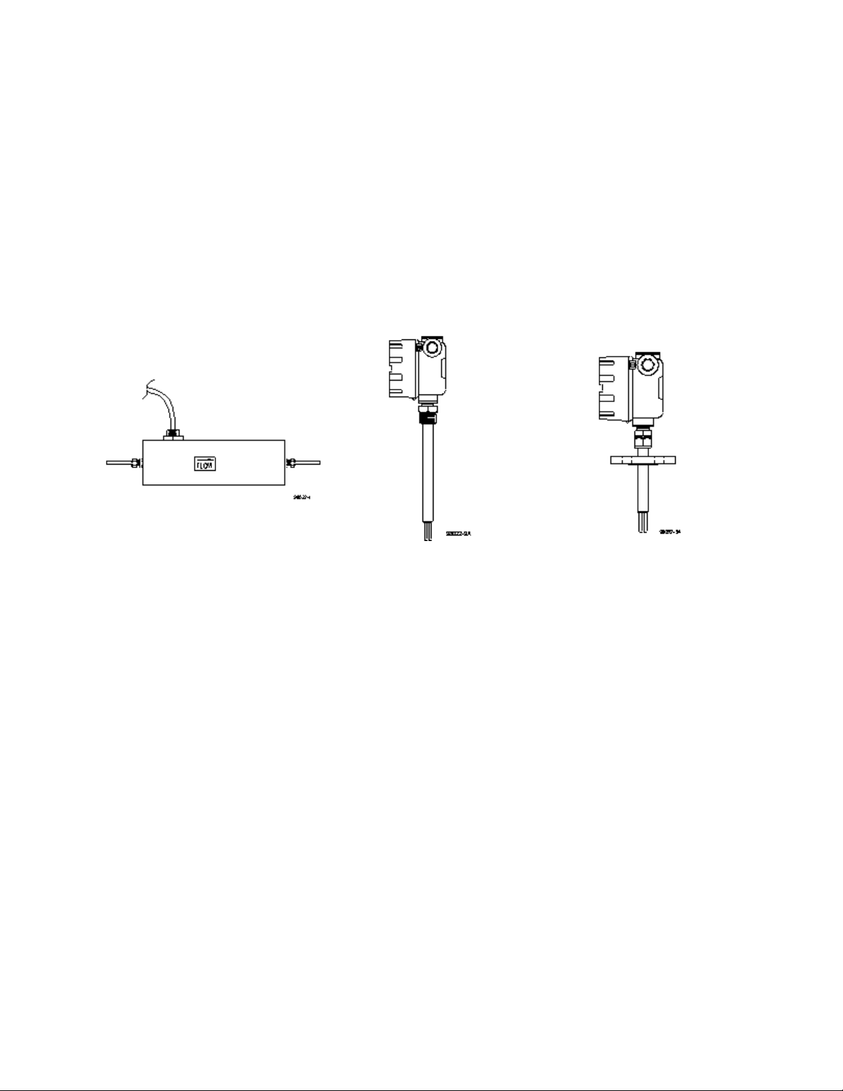
1.2 DESCRIPTION OF OPERATION
Rheotherm flow meters are available with various nonintrusive and intrusive transducer designs, but
they all use the same thermal sensing technique. Two temperature sensors are used — one is in thermal
equilibrium with the fluid and provides a fluid temperature reference, while the second temperature
sensor is located near a heater so that its temperature is slightly above that of the fluid. In tube style
transducers, the temperature sensors and heater are attached to the outside of the flow tube, whereas the
probe transducers have the sensors and heater located in the probe(s) that are inserted into the stream.
The amount of heat removed from the heated sensor by the stream is related to fluid velocity. Hence,
the measured temperature differential between the reference sensor and heated sensor is a function of
flow rate. Intek, Inc. is licensed to use this patented and trademarked flow measurement technique.
Nonintrusive tube transducer Example of Example of
probe probe with
with NPT fitting flange for mounting
1.3 PRECAUTIONS
1. Use proper input power — Check the label on the electronics for the input power
requirements.
2. Use reasonable care in handling the transducer. Do not try to disassemble the transducers;
there are no removable parts.
Tube (TU, TUL, TUS, etc.) — excessive twisting or bending can damage the sensor. The flow
tubes are thin-walled tubing.
Probes (NPT/2I, NPT/I, BF/2I, BF/I, etc.) — take care not to bend the probes or damage the
tips. Do not try to remove or turn the conduit junction box.
3. All tube sensors under ¼” should be supported by the sensor shell, not the tube stubs. Tube
sensors using junction boxes or sensors without junction boxes can be supported with the pipe
clamps or some other appropriate means. Tube sensors with junction box can be supported
using the brackets machined into the junction box.
MAN114 REV C.wpd
- 2 -
Page 5

4. Check the transducer maximum temperature rating — do not operate a transducer at or subject
it to a temperature above its specified limit.
5. Keep moisture out of the electronic enclosure and sensor junction box. Once cable
connections are made in the junction box, make sure the lid is tightly closed. Seal conduit
lines if they can become wet inside.
6. Keep transducer wetted surfaces clean and free of permanent layer build-up.
7. Do not exceed pressure limits of the tube or fittings.
8. Maintain a thermally stable environment (short-term) for the transducer and adjacent line.
(See SECTION 2 — INSTALLATION.)
These instructions cover installation, calibration and maintenance of Rheotherm meters in standard
configurations. Any special information pertaining to your unit is covered under CUSTOM
INFORMATION (SECTION 6). Time should be taken to carefully read these instructions prior to
installation of the equipment. Should any questions arise or problems occur, call Intek for immediate
assistance.
MAN114 REV C.wpd
- 3 -
Page 6

SECTION 2 ! INSTALLATION
. IMPORTANT: All transducers have a directional arrow on the tag
and/or etched into a metal part. Before installing a sensor, please note
proper flow direction. This is critical to sensor operation.
. IMPORTANT: If you have more than one Rheotherm unit, make sure
the complete serial number of the transducer matches the complete serial
number of the electronics. The transducer and electronics are a matched
set. Components with different serial numbers should not be
interchanged. The transducers have no user serviceable parts, so do not
try to disassemble, as permanent damage may result.
. IMPORTANT: If you are installing Rheotherm instruments in outdoor
environment, it is highly recommended that a “roof,” “shelter” or
protective cover to be provided to shield the transducer and electronics
from direct impact of environment conditions. Sudden and large changes
in temperature can affect instrument performance. Heat from the outside
can build up the temperature inside electronics enclosures, and can exceed
the temperature ratings for the electronics within.
2.1 TRANSDUCER
The transducer style supplied with your meter is listed in the model code number in SECTION 6.
Proper installation of the sensor is necessary for achieving accuracy and repeatability. Installation
suggestions for each type of standard transducer are given here. For custom transducer installations,
refer to CUSTOM INFORMATION — SECTION 6.
Be sure wetted surfaces are clean before installing. If cleaning is needed, use non-residue solvent and
wipe dry. If the sensor has a connector box, keep moisture out. Make sure the lid is tightly sealed and,
if supplied, the gasket is in place. Seal conduit lines at the connector box if conduit lines can become
wet.
1. Tube (nonintrusive) —
1
'16 and c transducers, unless they have optional ¼" O.D. ends,
particularly require special care in handling and installing to avoid damage to sensor tube
stubs.
. CAUTION: Tube transducers are made with thin-walled tubing —
use care when installing.
1
All tube transducers (other than
sections, typically 20 pipe diameters on the inlet and 6 to 10 diameters on the outlet.
Installation locations for tube style transducers should be selected to ensure a continuous and
uniform fluid flow within the sensing tube. Vertical or angled installations should be in
locations where the fluid is flowing up through the sensor. Connection in the line is via
compression fittings, hose with clamp, threaded fittings or flanges, whichever is appropriate.
Care must be taken not to transmit a twisting force through the transducer's midsection. The
'16 & c inch) should have straight line input and output
MAN114 REV C.wpd
- 4 -
Page 7

tube transducer, whether flanged or not, must not be used to pull other piping together or to
make up angular mismatch of fittings. The transducer junction box (if supplied) should never
be rotated for any reason.
1
The
'16" tube transducers may be sleeved with a c" tube for added support. Connection
should always be made to the
1
'16" tube, as there is no assured seal between the flow tube and
the c” support sleeve.
Some tube transducers have an integrally mounted cable; do not pull on this cable, or attempt
to remove the fitting where the cable enters the sensor shell.
Fluid temperatures other than ambient require special attention. Thermal gradients from one
end of the transducer to the other, as well as along the radius of the connection pipe, are
undesirable. Therefore, effective insulation should be installed around the inlet and outlet
straight line runs. Gradients which may exist in the line further up stream can be removed if
an insulated elbow is installed in the line prior to entering the straight line portion of the
plumbing. Metallic support braces for the sensor or adjoining plumbing can act as a heat sink
and cause operational problems in high temperature applications. The support braces should
be thermally isolated from the line to avoid large heat conduction effects.
If the transducer is for use above 300°F, it will have a side arm and connector box, where the
internal high temperature wiring is connected to the lower temperature transducer cable. Free
air should be allowed to flow around the side arm and connector box to keep the box cool.
The side arm can be insulated up to one third of its length from the transducer body.
In these applications, proper thermal control is vital to accurate meter performance. Nonuniform heat tracing, relay on/off temperature controllers and oscillating proportional type
control should always be avoided. Steam trace lines with good pressure regulation or properly
tuned proportional temperature control systems are effective in maintaining uniform fluid
temperature. A box around the sensor and inlet tubing is highly recommended for operating
temperatures higher than room ambient. Allow enough inlet tubing inside the box to allow
the fluid temperature to become the same temperature as the surrounding air. Separately
control the box air temperature at the same temperature as the incoming fluid temperature
to minimize thermally induced indication errors.
Flow stream conditioning must also be considered to maximize meter performance. Avoid
upstream protrusions and short distance straight runs. Flow pulsations, such as those created
by metering pumps, may cause the instrument to differ from the factory calibration.
Furthermore, if the flow is varied by stroke and by pump speed adjustment, the indication will
most likely be non-repeatable. If you are using a pump of this type, it is recommended that
a pulsation dampening device be used to provide smooth continuous flow. A second choice
would require readjustment of the instrument calibration (cal) potentiometer after installation
(See SECTION 4.2).
For liquid measurement systems using high pressure gas to force flow, the effects of the
absorbed gas must be considered. In these cases, sudden pressure drops up stream of the
sensor such as line size expansions, control valves, and pressure dropping regulators must be
avoided. Sudden pressure drops can cause the absorbed gas to release into the liquid, making
MAN114 REV C.wpd
- 5 -
Page 8

the flow sporadic and difficult to measure. Control valves should be placed down stream of
the sensor.
The ideal installation will provide the sensor with well established smooth flow, uniform
system temperature and consistent fluid media.
2. Intrusive Probes —
. IMPORTANT: Recommended straight run for best accuracy is 20
diameters up stream and 10 diameters down stream.
The various probe transducers are mounted through a threaded collar (NPT/2I and NPT/I) or
flange (BF/2I or BF/I). Other fittings and sensor designs are also available and are discussed
on the Custom Information page. Generally the probes are sized so the tips extend ½ to 1 inch
beyond the pipe center line when properly installed. There are exceptions to this in certain
applications; see CUSTOM INFORMATION (SECTION 6) as it applies.
Proper alignment of the sensor with flow is important; the flow direction is indicated on the
transducer tag and/or etched into the transducer. All dual probe transducers (NPT/2I, BF/2I)
are installed so that the two probes are side-by-side across the fluid stream. Never rotate the
junction box that houses the terminal cable connection. If this occurs the transducer could be
damaged and/or installed misaligned with the flow direction.
For high temperature applications, the sensor and surrounding line should be well insulated.
Leave a portion of the transducer neck un-insulated to allow heat dissipation before reaching
the junction box.
2.2 ELECTRONICS
Various types of electronics housings are available. These include NEMA 4, laboratory bench type,
explosion proof, and panel mount enclosures as well as special models to meet customer requirements.
These come in different sizes to accommodate options and special features.
1. NEMA 4
— The standard industrial housing, this enclosure is watertight (non-submersible)
when the door is properly clamped shut. The housing should be mounted such that wire/cable
ports are located at the bottom of the housing, to reduce problems associated with water spray,
condensation and settling of dust and dirt. An all stainless steel version for corrosive
environments is also available.
2. NEMA 7
— For use in hazardous (class I) environments. The lid should be closed and all
bolts tightened before the unit is powered up. If a NEMA 7/NEMA 4 enclosure was ordered,
the unit will have a rubber gasket in a groove in the top of the enclosure base. Conduit seals
are frequently required, so applicable code requirements should be met when installing the
conduit into the box.
MAN114 REV C.wpd
- 6 -
Page 9

3. Laboratory — This table-top unit is NEMA 1 only; do not spill liquid on it or use in a wet
environment. This unit typically has a grounded power cord, and all transducer and output
connections are located on the back of the enclosure.
4. Panel Mount
— For use in a control panel, mounted so the enclosure face is flush with the
panel surface. Most or all connections are made on the back of the enclosure. NEMA 1 only;
do not use in a wet environment.
The electronics housing should be installed keeping in mind the length and routing of the transducer
cable. Standard cable length is ten (10) feet but it can be specified up to 200 feet. If, after calibration
of the unit, the cable length is changed (a portion cut off or additional cable spliced on), there may be
a shift in the calibration due to the change in cable resistance. The size of this effect depends on the
amount of change. If a noticeable shift occurs, it may be calibrated out following the single point
calibration instructions in SECTION 4.2.
Unless otherwise specified, normal ambient environment for the electronics is 0-120°F. Recommended
maximum temperature is 135°F.
2.3 ELECTRICAL CONNECTIONS
1. Transducer Cable
— The standard transducer cable is 22 or 24 gauge, multi-conductor (6),
shielded cable with a PVC jacket. Connect the transducer cable to the electronics (and
transducer junction box if supplied) following the wire color codes shown on the wiring
diagram (Figure 1). Make sure all connections are tight. If the unit does not operate properly
after installation is completed, check these connections again.
In general the laboratory unit will have a plug-in connector for the transducer cable.
2. Power
— The input power requirement is listed on the tag on the electronics enclosure and
is shown on the input power connector; make sure the input power source is compatible. The
standard power requirement is 115 Vac, 60 Hz, ½ A, single phase. (For units going to Europe,
the standard is 230 Vac, 50 Hz, ¼ A, single phase.) Power connections are as shown in Figure
1. Laboratory units sold in the U.S. have a power cord with grounded plug.
. CAUTION: Never make or break transducer cable connections with
the electronics powered up (unless specifically instructed by factory to do
so).
As a general rule, if the flow is to be shut off or the flow line empty for long periods of time,
power to the unit should also be turned off. An on/off switch, provided by the customer, is
recommended for all industrial installations.
3. Output
unit has a 4-20 mA output, the standard is an isolated 4-wire transmitter with the current loop
powered by the Rheotherm electronics. Do not attempt to use with a system that also sources
the current unless the instrument was specifically ordered that way.
— Output connections are made to the output terminal as shown in Figure 1. If the
MAN114 REV C.wpd
- 7 -
Page 10

SECTION 3 ! OPERATION
3.1 START UP
Typically, the instruments come from the factory set up for the flow range of interest to the customer.
Following installation all that is required is to switch on power and initiate flow in the measurable flow
rate range. Flow sensors that are not calibrated directly on the fluid to be measured are so indicated in
this manual (SECTION 6) and require an in-line field calibration.
When power is first turned on, the output reading or signal will indicate full scale. After ten to forty-five
seconds (depending on flow range adjustment) the reading will stabilize. The instrument time constant
is generally between 4 to 12 seconds. Higher average flow rates will result in an observed faster
response time for a given unit.
3.2 GENERAL INFORMATION
The Rheotherm instrument is compensated for a wide range of both ambient and flowing media
temperatures. However, abrupt changes in the temperature of the flowing material can cause the
instrument output to deviate from the true representation of flow rate. A proper reading is obtained only
when the transducer is in thermal equilibrium with the material. Typically, a 20°F abrupt change in
temperature may require 40 seconds to stabilize. Temperature ramps should be kept below 1°C/minute.
Rheotherm instruments are calibrated for a particular fluid, either at the factory or in the field. If the
fluid changes properties, the calibration changes. Therefore, once calibrated, do not allow fluid
properties such as density and viscosity to change (other than the intrinsic changes which occur with
temperature variation). If the fluid is changed, a recalibration may be attempted following the procedure
in SECTION 4.2. If this procedure does not provide a good calibration for the range of interest on the
new fluid, contact the factory.
3.3 OPTIONS (Refer to those Sections that apply to the instrument you have purchased)
1. Analog Outputs
— The unit will have a 0-5 Vdc, 0-10 Vdc or 4-20 mA output. See SECTION
2.3 Output for a discussion of the 4-20 mA output.
2. Pulse Output
— For either pulse option shown below, the factory standard for pulse frequency
is 2 KHz at full scale flow. Specific units of volume or mass per pulse may also be supplied.
Unless otherwise specified, the minimum pulse duration is 250 :s.
A. Open collector — The (+) connection on the output terminal is the collector of a 2N3904
NPN transistor. The (
!) connection is the emitter of the same transistor. The pulse rate
is linear with flow. Recommended maximum current is 150 mA; maximum voltage is
36V.
B. Voltage pulse — This option uses the same circuit and connections as the open collector.
A 1k
S pull-up resistor is added and tied to either a +5V or a +12V voltage source. This
provides a 0-5V or a 0-12V voltage pulse.
MAN114 REV C.wpd
- 8 -
Page 11

3. Flow rate display — The standard display is a 3½ digit LED. The left digit shows only 0 or 1.
4. Totalizer — The standard totalizer is a 7 digit LED. It has a built-in lithium battery with an
8 year life for power off count retention. A reset button is located inside the enclosure, on the
totalizer printed wiring board. Additionally, the totalizer may be reset without opening the
enclosure through the use of a small magnet; a magnet is provided with the unit, and is located
on the inside surface of the enclosure door. To utilize this method, the magnet should be
placed on the outside of the enclosure after installation of the unit. Simply bring the magnet
close to the totalizer window, to the spot labeled "TOTALIZER RESET;" this action will reset
the totalizer.
Installation note
: To preserve its life during storage, the totalizer battery is shipped in the
"off" position. It must be turned "on" in order to properly retain its count when power to the
unit is disconnected. To turn the battery "on," go to the display board mounted in the
enclosure window. The shunt header is located near the battery (see drawing). Move the
shunt from the "off" position (left and center pins) to the "on" position (center and right pins).
If the unit is ever put into long term storage, the shunt should be returned to the "off" position
to preserve battery life.
5. Flow switch relay
— Flow switches may initially indicate a high flow rate even for zero flow
when power is first applied to the unit. Correct indication of flow will result after an initial
period which can extend to forty seconds depending on where the trip value is set. The relay
in standard flow switches is picked up (energized) when the flow rate is above a set point. A
loss of flow is therefore indicated in the event of loss of power to the sensor when connected
to N.C. contacts. If the switch option has been ordered for high flow indication, the relay will
be energized with flow below the trip value. See CUSTOM INFORMATION, SECTION 6
for details on operation of the relay.
MAN114 REV C.wpd
- 9 -
Page 12

3.4 OUTPUT CURVE
Figure 3 (p. 20) is the final linearized output curve for your unit. The instrument has been calibrated over
the actual flow rate range indicated on the ordinate (Y axis).
3.5 TRANSDUCER & ELECTRONICS FUNCTIONAL TESTS
A test of the Rheotherm instrument functional operation can be performed in three phases as outlined
below:
• Transducer continuity check, Diagram A on the next page.
• Transducer isolation check, Diagram B on the next page.
• Front end board TP4 signal to 4/20 mA output using Table II, calibration data.
1. The transducer continuity check is performed as follows:
A. Turn off power to the unit.
B. Disconnect the transducer cable from the electronics.
C. Make resistance measurements between the cable pairs as shown in Diagram A. The
readings should be as indicated; if not, consult factory for repair.
2. The transducer isolation check is performed as follows:
A. Turn off power to the unit.
B. Disconnect the transducer cable from the electronics.
C. Make the circuit connections illustrated in Diagram B.
D. Probe all the conductors and note the voltages with respect to the shield. All readings
should be less than 0.5 Vdc.
3. The sensor input to flow output of the electrical circuit is checked as follows:
A. Construct the dummy transducer as illustrated in Diagram C.
B. Turn off power to the unit.
C. Disconnect the transducer cable from the instrument.
D. Connect the dummy transducer to the instrument input.
E. Restore power.
F. Connect a DC voltmeter to the TEMP (+) pin on the front end board (see Figure 2 on page
18) and to GND (-). Connect a second DC voltmeter to pin
)T (+), and again to GND (-).
G. Vary the R1 & R3 pots of the dummy transducer to obtain values for TEMP and )T of
Table II Orginal Calibration Data for Functional Test. Compare the measured non-linear
output (TP4) and the indicated linear flow rate to data of Table II. If there are large
discrepancies between these numbers, contact factory for advice.
*resistors of dummy transducer
MAN114 REV C.wpd
- 10 -
Page 13

MAN114 REV C.wpd
- 11 -
Page 14

SECTION 4 ! MAINTENANCE
4.1 GENERAL MAINTENANCE
Certain precautions should be taken to insure proper performance of all models of flow instruments.
Since the measurement technique involves a signal resulting from heat transfer to the flowing medium,
care should be exercised to prevent build-up of varying layers on the walls of the transducer. Layers such
as bacterial growth, dried paints, gas bubbles and non-solubles can result in measurement below actual
flow rates. Periodic checks and cleaning should be performed to insure a clean pipe or probe wetted
surface.
It should be part of normal maintenance procedure to check the system for proper functioning.
Experience and other observable conditions should be utilized to determine the frequency of inspection.
Long term drift in the unit calibrations is not expected, but if a single point recalibration is required, refer
to SECTION 4.2. To test the flow switch action (if that option was ordered), the flow rate should be
reduced below (for low flow switch) or raised above (for high flow switch) the switching level. Then
check and insure relay action and continuity of the shut down or warning circuits which it operates.
The joints of all intrusive probes tips should be inspected for wear and corrosion.
4.2 SINGLE POINT FIELD CALIBRATION
When field calibration is required, for any reason, the simplest adjustment is a single point linear offset,
and this should usually be tried first. All calibrations should be done at normal operating temperature.
When a single point calibration (or recalibration) is required, it is performed as follows:
Establish a known flow rate in the upper third of the calibrated range that is shown on the output
curve (Figure 2). Adjust calibration potentiometer P2 (cal), Figure 1, for a correct output reading
or signal.
If P2 runs out of adjustment before the meter is reading correctly, P1 (see Board Layout P.17) can be
used to further offset the signal. Turning P1 clockwise decreases the signal. (Note: P1 has no effect on
some meters.)
Sometimes you may find the single point calibration is not sufficient to align the output over a wide flow
rate range. If so, a two-point offset/gain calibration can be performed as described below.
A. Establish a known flow rate at the low end (10-15% of full scale) of the factory calibrated
range (Figure 2, page 18).
1
Adjust P2 potentiometer, Figure 1, for an accurate output signal.
B. Establish a flow rate near 90-95% of full scale.1 Adjust "Flow Span" potentiometer, P3
(Figure 1) for an accurate output signal.
C. Repeat steps A and B until desired accuracy is achieved. Record flow vs. output relationships
for various flows and compare with output curve. Construct a new calibration curve if needed.
1 Ensure the flow meter output has been stabilized before making any adjustment. A strip chart or data logger monitoring
of the output is very helpful in determining when the flow has entered steady-state con ditions, especially at low or noisy
flows.
MAN114 REV C.wpd
- 12 -
Page 15

4.3 SPARE PARTS
There are no normally recommended spare parts to stock. The transducer and electronics are a matched
set and therefore are not interchangeable with others. Should a spare be needed, a complete unit should
be ordered and stocked. For AC powered units, the spare fuse is a ½A, fast acting fuse. Replace fuse
with Wickmann part number 3730500041 or equivalent. For units powered by 24 Vdc, the fuse is a 1A
slow blow fuse. Replace with Wickmann part number 3741100041 or equivalent.
4.4 TROUBLE SHOOTING
TABLE I. TROUBLE SHOOTING GUIDE
OBSERVATION PROBABLE CAUSE REMEDY
Output continually drifting
downward with constant flow
Output saturates high or low
— will not respond to flow
change
Output varies with flow but
not stable
1. Coating forming on wetted surface
of transducer
1. Loose transducer cable connections
2. Flow rate not yet within range of
meter
3. Meter/Calib switch in wrong
position
4. Transducer cable damaged
5. Bad electronic component
6. Blown fuse
1. Fluid temperature n ot stable
2. Fluid mixture not properly blended
3. Gas mixed w ith liquid
4. Flow not fully developed
1. Clean transducer periodically or
adjust calibratio n (cal)
potentiometer until layer build-up
stabilizes
1. Securely conn ect transduc er cable
2. Check flow
3. Check Meter/Calib sw itch is in
"meter" position
4. Check cable c ontinuity
5. Perform transducer and electronics
functional tes t (see SEC TION 3.5).
Write results down and consult
factory
6. Replace fuse as needed
1. Tune temperature controller, add
insulation and/or add static mixer
in front of transducer
2. Add static mixer in front of
transducer
3. Reduce gas pressure or check for
air ingress on suction side of pum p.
Refer to Installation Section
4. Check inlet and outlet for proper
straight line length & freedom
from obstructions
MAN114 REV C.wpd
- 13 -
Page 16

SECTION 5 ! CUSTOMER SERVICE
Intek's corporate philosophy is to solve our customer's difficult flow measurement problems. This means
that each instrument is custom configured and calibrated for the application. When you purchase a
Rheotherm instrument you also receive Intek's dedicated customer service. For sales or product service,
call your local representative or Intek directly at (614) 895-0301, 8AM to 5PM EST/EDT weekdays or
fax us anytime at (614) 895-0319. E-mail inquiries should be sent to sales@Intekflow.com or
techsupport@Intekflow.com. Our customer service staff will provide assistance promptly.
5.1 QUESTION ON EXISTING HARDWARE
To allow us to help you more quickly, please have the serial number of the equipment available before
you call.
5.2 TROUBLE SHOOTING
If you have reviewed SECTION 4.4 TROUBLE SHOOTING and have questions, please call our
experienced engineers for assistance. In many cases we can solve a problem over the phone. Please
provide as complete a description as possible of the problems encountered.
5.3 FACTORY AND FIELD SERVICE
If you request field service, Intek has experienced engineers available to meet your needs. Many of the
repairs or recalibrations will require returning the instrument to the factory. If a problem cannot be
solved over the phone, with your help, we will determine if factory service or field service will be the
best solution.
To request factory service, a Return Material Authorization (RMA) and purchase order is required. Our
customer service staff will assist you with the required information to return instruments for service.
5.4 DECONTAMINATION OF EQUIPMENT
For the safety of your personnel and ours, any hardware that has been in contact with potentially
hazardous liquids or gases must be properly decontaminated before shipment to Intek.
5.5 QUESTIONS ON NEW EQUIPMENT
For a new Rheotherm application or any liquid or gas flow measurement need, contact your local
Rheotherm representative or the Intek technical sales department at the above phone/fax numbers. Our
staff will be pleased to answer all questions and provide quotations.
MAN114 REV C.wpd
- 14 -
Page 17

SECTION 6 ! CUSTOM INFORMATION
6.1 UNIT IDENTIFICATION
Model no.:
Serial no.:
Customer identification:
6.2 CONFIGURATION
The configuration of this unit, as originally shipped from the factory:
Input Power:
Q 115 Vac, 50/60 Hz Q 230 Vac, 50/60 Hz Q 24 Vdc
Output:
Q 4-20 mA Q 0-5 Vdc Q 0-10 Vdc
Pressure Rating:
Calibrated Range:
Wetted Material:
Q 316 stainless steel Q other
Enclosure Type:
Q NEMA 4 Q NEMA 4X Q NEMA 7 (CL I, Grp BCD) Q Other
Process Connection:
6.3 SPECIAL INSTRUCTIONS
Reference Reference
Q None
Sensor Temperature Rating:
Q Installation
Q Single point Q Other
calibration required
MAN114 REV C.wpd
- 15 -
Page 18

TABLE II. ORIGINAL CALIBRATION DATA
FOR FUNCTIONAL TEST
Unit Serial Number -
I II III IV V VI
TEMP
Note: An offset of data in Column III and IV (with respect to Column II) may appear if the instrument has been field adjusted.
)T TP4
Linear Output
Instrument
Display
Flow Rate
MAN114 REV C.wpd
- 16 -
Page 19

Figure 1
MAN114 REV C.wpd
- 17 -
Page 20

Figure 2. Rheotherm® Signal Conditioner PWB Layout
MAN114 REV C.wpd
- 18 -
Page 21

JUST A HOLDING SPACE
Figure 3. Flow Rate vs. Output Curve
MAN114 REV C.wpd
- 19 -
 Loading...