

Page 1

WARRANTY
Intek, Inc. warrants each Rheotherm product to be free from defects
in material and workmanship under normal use and service, Intek's
obligation under this warranty being limited to making good any part
or parts thereof which shall, within one (1) year after delivery of such
product to the original purchaser, be returned to Intek with
transportation charges prepaid and which Intek's examination shall
disclose to its satisfaction to have been thus defective; this warranty
being expressly in lieu of all other warranties, express or implied and
all other obligation or liabilities on Intek's part. The purchaser will
assume all responsibility and expense for removal, decontamination
and reinstallation of equipment.
Rheotherm flow meters are manufactured under United States patent numbers 4,255,968; 4,942,763; 4,949,578; 5,485;754 and 5,752,411
Intek, Rheotherm, Rheovec, Rheomax and RheoVac are registered trademarks of Intek, Inc.
Intek, Inc.
751 Intek Way
Westerville, Ohio 43082-9057
TEL: (614) 895-0301 FAX: (614) 895-0319
www.intekflow.com
Page 2

TABLE OF CONTENTS
SECTION 1 ! GENERAL INFORMATION ........................................ - 1 -
1.1 INTRODUCTION ................................................. - 1 -
1.2 DESCRIPTION OF OPERATION .................................... - 2 -
1.3 PRECAUTIONS .................................................. - 2 -
SECTION 2 ! INSTALLATION ................................................. - 4 -
2.1 TRANSDUCER ................................................... - 4 -
2.2 ELECTRONICS .................................................. - 5 -
2.3 ELECTRICAL CONNECTIONS ..................................... - 6 -
SECTION 3
3.1 START UP ....................................................... - 7 -
3.2 GENERAL INFORMATION ........................................ - 7 -
3.3 ADJUSTING THE TRIP POINT ..................................... - 7 -
3.4 CHANGING THE TRIP POINT RANGE .............................. - 8 -
3.5 TRANSDUCER FUNCTIONAL TESTS ............................... - 8 -
Figure A. Transducer Continuity Check ...................................... - 9 -
Figure B. Transducer Isolation Check ....................................... - 9 -
SECTION 4
4.1 GENERAL MAINTENANCE ....................................... - 10 -
4.2 SPARE PARTS .................................................. - 10 -
4.3 TROUBLE SHOOTING ........................................... - 11 -
TABLE I. TROUBLE SHOOTING GUIDE .................................. - 11 -
SECTION 5
5.1 QUESTION ON EXISTING HARDWARE ............................ - 12 -
5.2 TROUBLE SHOOTING ........................................... - 12 -
5.3 FACTORY AND FIELD SERVICE .................................. - 12 -
5.4 DECONTAMINATION OF EQUIPMENT ............................ - 12 -
5.5 QUESTIONS ON NEW EQUIPMENT ............................... - 12 -
! OPERATION ..................................................... - 7 -
! MAINTENANCE ................................................ - 10 -
! CUSTOMER SERVICE .......................................... - 12 -
SECTION 6
! CUSTOM INFORMATION ....................................... - 13 -
6.1 UNIT IDENTIFICATION .......................................... - 13 -
6.2 CONFIGURATION ............................................... - 13 -
6.3 SPECIAL INSTRUCTIONS ........................................ - 13 -
Figure 1. Rheotherm® 100 Rev. B Signal Conditioner PCB Layout ..................... - 14 -
Figure 2. Rheotherm® Flow Switch Add-on Option ................................. - 15 -
Intek, Inc. 2010
Manual no. A100AFS9505 REV B
I:\OFFICE\WPMANUAL\Rheotherm\Model 100\MOD100FS.RVB
Page 3

SECTION 1 ! GENERAL INFORMATION
1.1 INTRODUCTION
Rheotherm flow switches offer reliable flow switch protection in liquids, gases and slurries. They can
be used for flow/no flow detection, or specific low and/or high level alarms over a given 10 to 1 flow
range. They are manufactured exclusively by Intek, Inc. and employ a patented thermal technique used
by industry since 1978. The unique transducer designs have protected sensors, are easy to install and
require little or no maintenance.
Each Rheotherm 100FS flow switch consists of two elements a transducer and an electronics unit.
The transducers come in two basic designs, intrusive and nonintrusive (SECTION 2.1). Design selection
is based on application constraints or customer preference. The electronics, for signal processing, are
housed in one of two basic enclosure styles (SECTION 2.2). Again, selection is based on application
requirement.
Key features of Rheotherm flow switches and flow meters are:
Nonintrusive flow monitoring
outside the flow tube.
No moving parts There are no rotating, translating, undulating or oscillating parts to wear,
stick, break or fatigue.
Chemical compatibility
metals or alloys. There are no internal seals in a TU type transducer. Most sensors are 316
SS or 316 SS and nickel braze.
Flexibility
average velocity. Flow rate, totalization and fluid temperature displays or output signals are
available as well as rangeability up to 100:1 or more.
Fluid pressure options
Withstands over ranging
flow rates many times higher than originally specified.
Immunity to shock and vibration
Rheotherm meters can be ordered calibrated for mass or volumetric units or in
The wetted surface(s) can be any of a number of corrosion resistant
to 10,000 psi.
For pipe sizes from .030 to 1 inch, flow sensing is done from
No damage or change in operation will occur due to excessive
.
Optional nuclear radiation hardening
Range of application
ducts.
includes measurements in capillary tubes to large diameter pipes or
.
- 1 -
Page 4
1.2 DESCRIPTION OF OPERATION
Rheotherm flow meters are available with various nonintrusive and intrusive transducer designs, but
they all use the same thermal sensing technique. Two temperature sensors are used one is in thermal
equilibrium with the fluid and provides a fluid temperature reference, while the second temperature
sensor is located near a heater so that its temperature is slightly above that of the fluid. In a TU
transducer, the temperature sensors and heater are attached to the outside of the flow tube, whereas the
probe transducers have the sensors and heater located in the probe(s) that are inserted into the stream.
The amount of heat removed from the heated sensor by the stream is related to fluid velocity. Hence,
the measured temperature differential between the reference sensor and heated sensor is a function of
flow rate. Intek, Inc. is licensed to use this patented and trademarked flow measurement technique.
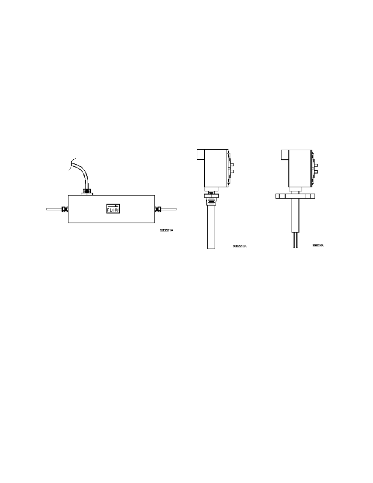
Nonintrusive transducer
(TU)
1.3 PRECAUTIONS
1. Use proper input power Check the label on the electronics for the input power
requirements.
2. Use reasonable care in handling the transducer. Do not try to disassemble the transducers;
there are no removable parts.
TU excessive twisting or bending can damage the sensor. The flow tubes are thin-walled
tubing.
Probes (NPT/2I, NPT/I, BF/2I, BF/I, etc.) take care not to bend the probes or damage the
tips. Do not try to remove or turn the conduit junction box.
3. Check the transducer maximum temperature rating do not operate a transducer at or subject
it to a temperature above its specified limit.
4. Keep moisture out of the electronic enclosure and sensor junction box. Once cable
connections are made in the junction box, make sure the lid is tightly closed. Seal conduit
lines if they can become wet inside.
Example of single probe
with NPT fitting
Example of dual probe
with flange fitting
- 2 -
Page 5

5. Keep transducer wetted surfaces clean and free of permanent layer build-up.
6. Do not exceed pressure limits of the tube or fittings.
7. Maintain a thermally stable environment (short-term) for the transducer and adjacent line.
(See SECTION 2 INSTALLATION.)
These instructions coverinstallation, operationand maintenance of Rheotherm flow switches in standard
configurations. Any special information pertaining to your unit is covered under CUSTOM
INFORMATION (SECTION 6). Time should be taken to carefully read these instructions prior to
installation of the equipment. Should any questions arise or problems occur, call Intek for immediate
assistance.
- 3 -
Page 6

SECTION 2 ! INSTALLATION
2.1 TRANSDUCER
. IMPORTANT: All transducers have a directional arrow on the tag
and/or etched into a metal part. Before installing a sensor, please note
proper flow direction. This is critical to sensor operation.
. IMPORTANT: If you have more than one Rheotherm unit, make sure
the complete serial number of the transducer matches the complete serial
number of the electronics. The transducer and electronics are a matched
set. Components with different serial numbers should not be
interchanged. The transducers have no user serviceable parts, so do not
try to disassemble, as permanent damage may result.
The transducer style supplied with your meter is listed in the model code number in SECTION 6.
Proper installation of the sensor is necessary for achieving accuracy and repeatability. Installation
suggestions for each type of standard transducer are given here. For custom transducer installations,
refer to CUSTOM INFORMATION SECTION 6.
Be sure wetted surfaces are clean before installing. If cleaning is needed, use non-residue solvent and
wipe dry. If the sensor has a connector box, keep moisture out. Make sure the lid is tightly sealed and,
if supplied, the gasket is in place. Seal conduit lines at the connector box if conduit lines can become
wet.
1
1. TU (nonintrusive) TU
'16 and TUc transducers, unless they have optional ¼" O.D. ends,
require special care in handling and installing to avoid damage to sensor tube stubs.
. CAUTION: TU transducers are made with thin-walled tubing use
care when installing.
Straight run for a flow switch is not a requirement, but for best repeatability some straight run
is useful, such as 10 to 20 pipe diameters on the inlet and 6 to 10 diameters on the outlet. If
installed vertically, the flow should be going up through the sensor. Connection in the line
is via compression fittings, hose with clamp, threaded fittings or flanges, whichever is
appropriate. Care must be taken not to transmit a twisting force through the transducer's
midsection. The TU transducer, whether flanged or not, must not be used to pull other piping
together or to make up angular mismatch of fittings. The transducer junction box (if supplied)
should never be rotated for any reason.
1
Typically, TU
should always be made to the
the sleeve.
'16 transducers are sleeved with a c" tube for added support. Connection
1
'16" tube, as there is no assured seal between the
1
'16 tube and
- 4 -
Page 7

Some TU transducers have an integrally mounted cable; do not pull on this cable, or attempt
to remove the fitting where the cable enters the shell.
Fluid temperatures other than ambient require special attention. Thermal gradients from one
end of the transducer to the other, as well as along the radius of the connection pipe, are
undesirable. Therefore, effective insulation should be installed around the inlet and outlet
straight line runs. Gradients which may exist in the line further up stream can be removed if
an insulated elbow is installed in the line prior to entering the straight line portion of the
plumbing. Metallic support braces for the sensor or adjoining plumbing can act as a heat sink
and cause operational problems in high temperature applications. The support braces should
be thermally isolated from the line to avoid large heat conduction effects.
If the transducer is for use above 300°F, it will have a side arm and connector box, where the
internal high temperature wiring is connected to the lower temperature transducer cable. Free
air should be allowed to flow around the side arm and connector box to keep the box cool.
The side arm can be insulated up to one third of its length from the transducer body.
The ideal installation will provide the sensor with well established smooth flow, uniform
system temperature and consistent fluid media.
2. Intrusive Probes
Straight run is not critical, but if trying to hold a precise set point, some straight run is
useful, such as 10 to 20 pipe diameters on the inlet and at least 6 diameters on the outlet.
The various probe transducers are mounted through a threaded collar (NPT/2I and NPT/I) or
flanged tee (BF/2I or BF/I). Other fittings and sensor designs are also available and are
discussed on the Custom Information page. Generally the probes are sized so the tips extend
½ to 1 inch beyond the pipe center line when properly installed. However, for larger pipes,
the probes may extend in c of a diameter from the wall.
Proper alignment of the sensor with flow is important; the flow direction is indicated on the
transducer tag and/or etched into the transducer. All dual probe transducers (NPT/2I, BF/2I)
are installed so that the two probes are side-by-side across the fluid stream. Never rotate the
junction box that houses the terminal cable connection. If this occurs the transducer could be
damaged and/or installed misaligned with the flow direction.
For high temperature applications, the sensor and surrounding line should be well insulated.
Leave a portion of the transducer neck un-insulated to allow heat dissipation before reaching
the junction box.
2.2 ELECTRONICS
Two types of electronics housings are typically available for flow switches. These are NEMA 4 (or 4X)
and explosion-proof. These come in different sizes to accommodate options and special features.
- 5 -
Page 8

1. NEMA 4 The standard industrial housing, this enclosure is watertight (non-submersible)
when the door is properly clamped shut. The housing should be mounted such that wire/cable
ports are located at the bottom of the housing, to reduce problems associated with water spray,
condensation and settling of dust and dirt. An all stainless steel version (4X) for corrosive
environments is also available.
2. NEMA 7
bolts tightened before the unit is powered up. If a NEMA 7/NEMA 4 enclosure was ordered,
the unit will have a rubber gasket in a groove in the top of the enclosure base. Conduit seals
are frequently required, so applicable code requirements should be met when installing the
conduit into the box.
The electronics housing should be installed keeping in mind the length and routing of the transducer
cable. Standard cable length is six feet but it can be specified up to 200 feet. If the cable length is
changed (a portion cut off or additional cable spliced on), there may be a shift in the set point due to the
change in cable resistance. The size of this effect depends on the amount of change. Follow instructions
for adjusting the trip level in SECTION 3.
Unless otherwise specified, normal ambient environment for the electronicsis 40-120°F. Recommended
maximum temperature is 135°F.
2.3 ELECTRICAL CONNECTIONS
1. Transducer Cable
shielded cable with a PVC jacket. Connect the transducer cable to the electronics (and
transducer junction box if supplied) following the wire color codes shown on the wiring
diagram (Figure 1). Make sure all connections are tight. If the unit does not operate properly
after installation is completed, check these connections again.
For use in hazardous (class I) environments. The lid should b e closed and all
The standard transducer cable is 22 or 24 gauge, multi-conductor (6),
2. Power
is shown on the input power connector; make sure the input power source is compatible. The
standard power requirement is 120 Vac, 60 Hz, ½ A, single phase. (For units going to Europe,
the standard is 220 Vac, 50 Hz, ½ A, single phase.) Power connections are as shown in
Figure 1.
The input power requirement is listed on the tag on the electronics e nclosure and
. CAUTION: Never make or break transducer cable connections with
the electronics powered up (unless instructed by factory to do so).
As a general rule, if the flow is to be shut off or the flow line empty for long periods of time,
power to the unit should also be turned off. An on/off switch, provided by the customer, is
recommended for all industrial installations.
3. Output
instrument was ordered with two (2) relays, be sure to note which one will be used for low
flow and which one will be used for high flow detection.
The relay connection s are made to the small switch board terminals. If the
- 6 -
Page 9

SECTION 3 ! OPERATION
3.1 START UP
Typically, Rheotherm flow switches come from the factory set up for a 10 to 1 flow rate range, and with
the trip level set approximately as requested by the customer. SECTION 6 shows whether the unit is
factory set as a low flow switch or as a high flow switch (see 1 or 2 below as appropriate). The trip level
can be adjusted using the instructions in SECTION 3.3.
When power is first turned on, the flow switch may indicate a high flow rate, even if there is no flow
occurring. Correct indication of flow level will result after an initial period, which can extend to about
forty (40) seconds and depends on where the level adjust is set.
For standard flow switches, the relay operates as stated below. See SECTION 6 for the type of flow
switch you have. For nonstandard units, the relay operation is also described in SECTION 6.
1. Low Flow Switch
above the trip level. Therefore, an alarm condition (relay de-energizes) occurs when the flow
rate drops below the trip level or there is a loss of power to the sensor (N.C. contact is made).
2. High Flow Switch
below the trip level. Therefore, an alarm condition (relay de-energizes) occurs when the flow
rate is higher than the trip level, or there is a loss of power to the sensor (N.C. contact is
made).
For operation as a level switch, see SPECIAL INSTRUCTIONS (SECTION 6.3).
3.2 GENERAL INFORMATION
The Rheotherm instrument is compensated for a wide range of both ambient and flowing media
temperatures. However, abrupt changes in the temperature of the flowing material can cause the
instrument to read the flow rate improperly, which could lead to an inappropriate tripping of the relay
or a delay in reading loss of flow. A proper reading is obtained only when the transducer is in thermal
equilibrium with the material. Typically, a 20°F abrupt change in temperature may require 40 seconds
to stabilize.
In general the heater used in the transducer does not develop enough power to cause damage to the
system in the absence of flow. This includes those used in liquids even if the line becomes empty and
filled with air. During long shutdowns, it is recommended that the power to the unit be turned off. (This
does not apply to units for which "no flow" is the standard condition.)
The relay is energized (N.O. contact is made) when the flow rate is
The relay is energized (N.O. contact is made) when the flow rate is
- 7 -
Page 10

3.3 ADJUSTING THE TRIP POINT
Adjust the flow switch trip level as follows:
1. Establish a flow rate at the desired trip level. (This should be done with flow in the line, not
at zero flow. Select a flow rate below your normal usage. One example would be to use 50%
of your lowest normal flow rate as the set point.)
2. On the small switch board, if LED is green, adjust "Trip" potentiometer clockwise* until the
relay de-energizes (LED turns red). This is the alarm condition.
3. If LED is red, adjust "Trip" potentiometer slowly counterclockwise* just until the relay
energizes (LED turns green).
* Reverse direction of turns if the switch is used as a high flow alarm.
4. If the relay cannot be made to drop out over the full range of the "Trip" potentiometer, see
SECTION 3.4.
3.4 CHANGING THE TRIP POINT RANGE
Generally, the instructions in SECTION 3.3 should be followed for setting the trip point of the flow
switch. In some cases, the "Trip" potentiometer may not have enough adjustment on a particular fluid;
or you may wish to set the trip level beyond the range for which the flow switch was originally set up.
If this is the case, the settable range can be changed by the following procedure:
1. Attach a current meter to the + and
! output terminals (see Figure 1. Rheotherm 100 Signal
Conditioner PCB Layout).
2. Establish a flow rate close to the desired trip level.
3. Adjust "FLOW ZERO" potentiometer (P2) until the current meter reads 12 mA.
4. Follow instructions in SECTION 3.3 for setting the trip level.
3.5 TRANSDUCER FUNCTIONAL TESTS
A test of the Rheotherm instrument transducer can be performed as outlined below:
1. Transducer continuity check, Figure A.
2. Transducer isolation check, Figure B.
1. The transducer continuity check is performed as follows (see Figure A):
A. Disconnect the transducer cable from the electronics.
B. Make resistance measurements between the cable pairs as shown in Figure A. The
readings should be as indicated; if not, consult factory for repair.
- 8 -
Page 11

2. The transducer isolation check is performed as follows (see Figure B):
A. Disconnect the transducer cable from the electronics.
B. Make the circuit connections illustrated in Figure B.
C. Probe all the conductors and note the voltage with respect to the shield. All readings
should be less than 0.5 Vdc. The yellow (Y) wire should also be isolated from the green
(G) wire. Connect the "low" test lead to Y and probe the Blu and G wires with the "high"
lead. Again, the meter should read less than 0.5 Vdc; if not, consult factory for service.
Similarly, check the isolation between the Blu and G wires.
- 9 -
Page 12

SECTION 4 ! MAINTENANCE
4.1 GENERAL MAINTENANCE
Certain precautions should be taken to insure proper performance of all models of flow instruments.
Since the measurement technique involves a signal resulting from heat transfer to the flowing medium,
care should be exercised to prevent build-up of varying layers on the walls of the transducer. Layers
such as bacterial growth, dried paints, gas bubbles and non-solubles can result in measurement below
actual flow rates. Periodic checks and cleaning should be performed to insure a clean pipe or probe
surface.
It should be part of normal maintenance procedure to check the system for proper functioning.
Experience and otherobservable conditions should be utilized to determine the frequency of inspection.
To test the flow switch action. the flow rate should be reduced below (for low flow switch) or raised
above (for high flow switch) the switching level. Then check and insure relay action and continuity of
the shut down or warning circuits which it operates.
4.2 SPARE PARTS
There are no normally recommended spare parts to stock. The transducer and electronics are a
matched set and therefore are not interchangeable with others. Should a spare be needed, a complete
unit should be ordered and stocked.
If fuse replacement is ever needed, for AC powered units , use a Wickman part no. 3730500041 (½A,
fast acting fuse) or equivalent. For units powered by 24 Vdc, the fuse is a 1A, slow blow fuse and may
be replaced with Wickman part no. 3741100041 or equivalent.
- 10 -
Page 13

4.3 TROUBLE SHOOTING
TABLE I. TROUBLE SHOOTING GUIDE
OBSERVATION PROBABLE CAUSE REMEDY
Flow trip level continually
drifting downward with constant
flow.
After switch has been operating
properly:
a. Relay trips with flow above
trip level and cannot be
adjusted using SECTION 3.3
instructions.
b. Relay does not trip when flow
falls below trip level and
cannot be adjusted using
SECTION 3.3 instructions.
Relay cannot be made to trip by
adjusting "Trip" potentiometer.
Switch level varies with flow, but
not stable.
Coating forming on wetted
surface of transducer.
1. Loose transducer cable
connections.
2. Transducer cable
damaged.
3. Bad electronic
component.
4. Blown fuse.
1. Initial flow rate estimate
was too low or too high.
2. Flow media change.
1. Fluid temperature not
stable.
2. Fluid mixture not
properly blended.
3. Air mixed with liquid.
4. Flow not fully
developed.
1. Clean transducer
periodically.
1. Securely connect
transducer cable.
Replace if damaged.
2. Replace fuse as needed.
3. Perform transducer
functional tests
(SECTION 3.5).
1. Follow instructions
under SECTION 3.4 to
adjust trip level range.
2. Consult factory.
1. Correct conditions to
remove obvious cause.
2. Check inlet an outlet for
proper straight line
length & freedom from
obstructions.
3. Consult factory.
- 11 -
Page 14

SECTION 5 ! CUSTOMER SERVICE
Intek's corporate philosophy is to solve our customer's difficult flow measurement problems. This
means that each instrumentis custom configured and calibrated for the application. When you purchase
a Rheotherm instrument you also receive Intek's outstanding customer service. For sales or product
service, call your local representative or Intek directly at (614) 895-0301, 8AM to 5PM EST/EDT
weekdays or fax us anytime at (614) 895-0319. E-mail inquiriesshould be sent to sales@Intekflow.com
or techsupport@Intekflow.com. Our customer service staff will provide assistance promptly.
5.1 QUESTION ON EXISTING HARDWARE
To allow us to help you more quickly, please have the serial number of the equipment available before
you call.
5.2 TROUBLE SHOOTING
If you have reviewed SECTION 4.4 TROUBLE SHOOTING and have questions, please call our
experienced engineers for assistance. In many cases we can solve a problem over the phone. Please
provide as complete a description as possible of the problems encountered.
5.3 FACTORY AND FIELD SERVICE
If you request field service, Intek has experienced engineers available to meet your needs. Many of the
repairs or recalibrations will require returning the instrument to the factory. If a problem cannot be
solved over the phone, with your help, we will determine if factory service or field service will be the
best solution.
To request factoryservice, a Return Material Authorization (RMA) and purchase order is required. Our
customer service staff will assist you with the required information to return instruments for service.
5.4 DECONTAMINATION OF EQUIPMENT
For the safety of your personnel and ours, any hardware that has been in contact with potentially
hazardous liquids or gases must be properly decontaminated before shipment to Intek.
5.5 QUESTIONS ON NEW EQUIPMENT
For a new Rheotherm application or any liquid or gas flow measurement need, contact your local
Rheotherm representative or the Intek technical sales department at the above phone/fax numbers. Our
staff will be pleased to answer all questions and provide quotations.
- 12 -
Page 15

SECTION 6 ! CUSTOM INFORMATION
6.1 UNIT IDENTIFICATION
Model no.:
Serial no.:
Customer identification:
6.2 CONFIGURATION
The configuration of this unit, as originally shipped from the factory:
Flow switch setting:
Q Low flow switch Q High flow switch Q Other
Input Power:
Q 115 Vac, 50/60 Hz Q 230 Vac, 50/60 Hz Q Other
Line Connection:
6.3 SPECIAL INSTRUCTIONS
Reference Reference
None Installation
Other
Trip level adjustment required for start up
- 13 -
Page 16

FIGURE
~---
i
I
'
i
i ' '
i
:;:=-0-_:;..!~·
\
~~,_-:
-
--~
-·----
lliiiii[:::::J
I
-1
::JJ
-
)>
z
CJ)
-
0
c
-
0
m
-
>
L()
I
0
::JJ
z
.,
c
-1
-
-
-
to
:JJ
~
0
:E
~
-<
00
1.
Rheotherm
:s:
rl
_,
rl
:;q_
Sl
I
0
@
@
@
@
iJ
@
@
100
Rev. B Signal
TEMP
TPl
TP2
TP4
GND
GND
6TZ
1
Pl
Lfl
0_
---:)
-
z
D
u
-
r=q
r---i
<i
U
Conditioner
@©
@©
@©
@©
@©
@©
@©
JP6
SPARE
Te
vee
GND
N/e
GND
+S.OOOV
GND
GND
ZERO
PCB
p
2
Layout
C\1
a)
0
~
0
:.c
1:10
S:ai
o..::.::=
.f;G>t::
-c
Q)
..::.::-(jJ
Q)
....
Q)
-lOs:
£1'-
t)
f--
=:>
0
m~
__j
[:jm
Q::U
Q_
ocr:::
ow
z
@0
2f--
a::O
wz
IO
t-U
o__j
w<C
Iz
O::::o
0
:z:
(.!)
:z:
3::
<(
Cl::
Cl
.......
Cl
0
u
'-'--'
(.!)
<(
u
("..J
CJ)
""'"""
c..o
n
CJ)
CJ)
LO
<(
0
:z:
__J
:::l
S!i'
n
"-
0
n
I-
'-'--'
'-'--'
:c
(./")
<(
........__
:z
'-'--'
__J
<(
u
(./")
L
0
<(
E
0
C\J
I
~
~=====1-
~=~=====j~
\Y
~======1~
~
~~\Y==~::I
_~_k_T_s_-3_6
____
~~~~--~CD~:
Spare
~~
0
a:
z w
0
3:
~
w
()
~
0
t'·
I
~:
~
~
CAL
FLOw
Te
SPAN
See
for
FLOw
SPAN
CDO
section
correct
ZERO
NOT
6
of
input
ADJUST)
the
manual
power
-14-
Page 17

 Loading...