

Integrated Visual Data Technology Inc. SkidWeigh ED2 Series, SkidWeigh ED2-2X Series, SkidWeigh ED2-AT Series Installation & Calibration Manual
Installation & Calibration Manual
SkidWeigh ED2 Series
Lift Truck Onboard Check Weighing Scale
ED2 V1600
Integrated Visual Data Technology Inc. 3439 Whilabout Terrace, Oakville, Ontario, Canada L6L 0A7

General Installation Guide
This SkidWeigh ED2 system version V1600, installation & calibration guide describes how to install, calibrate, test and
use your lift truck onboard check weighing scale. Following the instructions in this guide will enable you to get your
system operating quickly and with ease. In the event that you require additional assistance, please contact technical
support below.
Integrated Visual Data Technology Inc.
3439 Whilabout Terrace
Oakville, Ontario
L6L 0A7
Phone:! 905-469-0985
Email:! support@sidweight.com
Web:! www.skidweigh.com
Safety
Always disconnect the vehicle battery before installing SkidWeigh systems. Make sure that the digital indicator, pressure
transducer and any other associated cables are securely mounted and do not impede any of the vehicle’s controls. Use
care when routing the component cables and where they will be protected. Use commonly accepted install practices for
after market industrial vehicle electronic devices. The installation of SkidWeigh systems should only be performed by an
acknowledged lift truck technician or other with competent knowledge of electrical and hydraulic systems.
Here are two acceptable methods of making a wire connections:
1.Soldering your connections (recommended)
2.Crimp connectors (with the use of the proper crimping tool)
Regardless of the method you choose, ensure that the connection is mechanically sound and properly insulated. Use
high quality electrical tape and shrink tubing where necessary. This product is connected directly to the vehicle’s ignition
switch, 12 to 55 VDC. There is no On-Off switch on the digital indicator.
Electro-Magnetic Compatibility
CE conformity to EC directive 89/336 (EMC) by application of harmonized standards: Interference stability EN 61000-6-2
and EN 61326-1 interference emit EN 61000-6-3, EN 61326-1 for the pressure transducer.
Integrated Visual Data Technology Inc. 3439 Whilabout Terrace, Oakville, Ontario, Canada L6L 0A7
SkidWeigh ED2 Version 1600
Our policy is one of continuous improvement and the information in this document is subject to change without notice.
Check that software version displayed on the LED display is reflective of this manual.
Overview of Components
The standard SkidWeigh ED2 check weighing system kit consist of two main components:
* Digital indicator with external overload audio warning, wiring harness and anti-vibration mounting bracket.
* Hydraulic pressure transducer with 3 wire connection cable.
* Installation & calibration manual as well as quick reference operator usage instructions.
Operational Principal
The SkidWeigh ED2 operational principal is based on
mounting a pressure transducer into the vehicles hydraulic
lifting circuit between the lift control valve and lifting cylinder(s).
Upon usage proprietary software will automatically activate
the “weighing cycle algorithm ” when a skid load is lifted just
above the ground. The increase in pressure is converted
through an electronic signal at the sample rate of 16000
readings per session which is then converted into a load
weight reading.
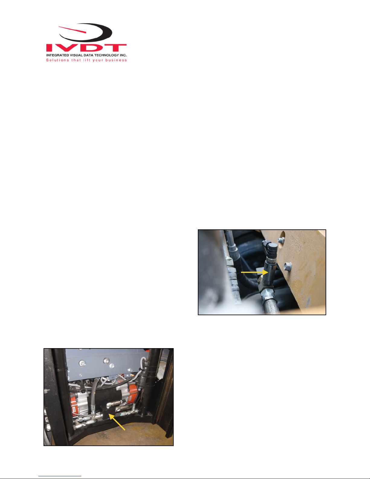
Installing the Pressure Transducer
The pressure transducer must be installed in the hydraulic lift
line between the lift control valve and lift cylinder(s). In
some cases you can install the pressure transducer in the flow
divider, drilling and tapping for 1/4”-18 NPT male in spare plug
or in the body of the flow divider. Also, you can drill and tap
on any “larger elbow” that might be available in the hydraulic
lift circuit found in vehicles with larger hoses to accommodate
larger vehicle lifting capacities.
Integrated Visual Data Technology Inc. 3439 Whilabout Terrace, Oakville, Ontario, Canada L6L 0A7
Flow Divider
Pressure
Transducer
Flow Divider
T-Piece
Pressure Transducer Installation
Precautions
Before installation of the pressure transducer the hydraulic lift
circuit must be pressure free. There are two ways to do that:
1. Place the forks on the ground at their lowest position and
make sure the hydraulic system pressure is completely free by
tilting the mast forward. The chain(s) should be slack.
2. Lift the forks and position them on the top of a supporting
fixture. Start lowering the lift cylinder into its lowest position. Ensure that the chain(s) is slack.
Make sure that that pressure transducer when installed will not
touch or obstruct any assembly or moving parts during
operation. The pressure transducer has a 1/4”-18 NPT male
thread. Use thread seal to ensure tight fit.
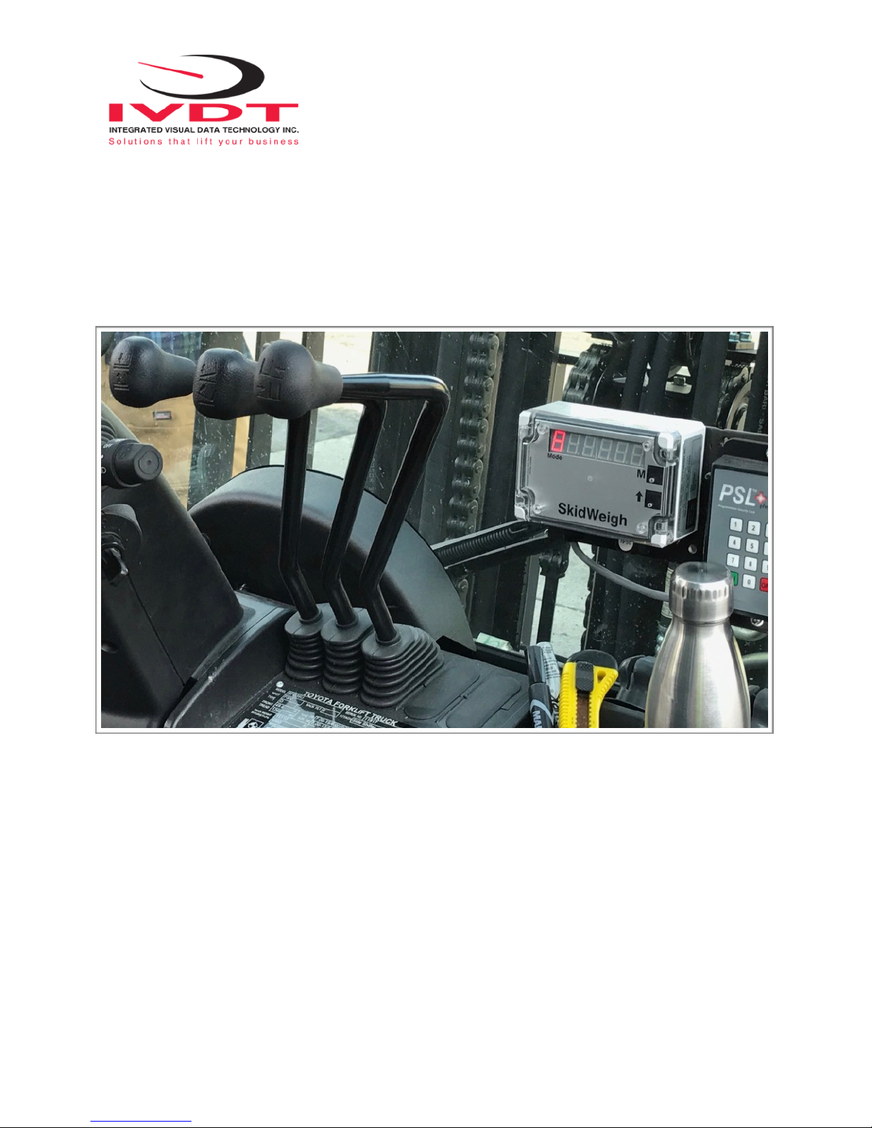
Selecting the Mounting Location for
the Digital Indicator
Use the anti vibration mounting bracket and fasten the digital indicator on the vehicle dashboard, side rail, or over head
guard, preferably on the right hand side. There are many examples of mounting locations that will depend on the vehicle
model. Each SkidWeigh ED2 kit comes complete with flat universal mounting brackets designed for mounting on the
overhead guard.
Choose the correct location and make sure that:
1. The Indicator is visible and within reach of the operator.
2. The location does not impede the operator safety entering the vehicle or obstruct operational sight lines
Integrated Visual Data Technology Inc. 3439 Whilabout Terrace, Oakville, Ontario, Canada L6L 0A7
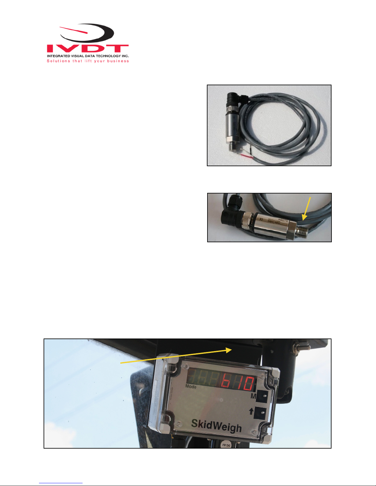
Mounting Bracket
3 Wire Pressure
Transducer Cable
1/4”-18 NPT male thread
 Loading...